Article

Grid Connection Studies for Large-Scale Offshore Wind Farms Considering High Penetration of Regional Renewables

1
Department of Electric and Electrical Engineering, Korea University, Seoul 02841, Korea
2
Department of Electrical Engineering, Yeonsung University, Seoul 03722, Korea
3
Department of Occupational Health and Safety Engineering, Semyung University, Jecheon 27136, Korea
4
Offshore Wind Farm Business Department, Korea Electric Power Corporation, Naju 58322, Korea
*
Author to whom correspondence should be addressed.
Sustainability 2022, 14(2), 1015; https://doi.org/10.3390/su14021015
Submission received: 5 December 2021 / Revised: 10 January 2022 / Accepted: 11 January 2022 / Published: 17 January 2022

Abstract

:
There is a global focus on adding renewable energy sources to the mix of energy supplies. In this study, the grid connections for large-scale offshore wind farms in areas that have high penetration of renewable energy sources were examined. System strength evaluation considering the interaction of wind farms and inverter-based resources (IBRs) was performed; the fault current was then analyzed to determine their contribution to the total fault current at a bus level. These studies revealed that the interaction between offshore wind farms and IBRs may make the power system weaker, and it is possible that fault current contributions from offshore wind farms can violate the capacity limit of existing circuit breakers. The results of steady-state analysis were verified through case studies focused on the southwest area of the Korea Electric Power Corporation (KEPCO) system where large-scale offshore wind farms are planned to be established and connected. Power system planners will benefit from the results of this study with a better understanding of the factors to consider when integrating large-scale wind farms in areas with high penetration of renewables.

1. Introduction

Large-scale offshore wind farms have the potential to make a significant impact on the future development of carbon-free power systems [1]. It is recognized that the growing connections of large-scale offshore wind farms to the mainland provide challenges in terms of planning the transmission system [2,3,4]. Accordingly, a recent trend is to study technology to evaluate the potential site suitability of a wind turbine using remote sensing technology [5]. In particular, the transmission network with offshore wind generation can have issues such as low system strength and variation of fault current due to the converter technologies. Such instability is related to the reduction of short-circuit capacity provided by synchronous generators. Synchronous generators are key elements for maintaining the voltage stability of the system by providing the contribution to the short-circuit capacity. Fundamentally, synchronous generators can control the excitation current to maintain the terminal voltage during a fault. In addition, synchronous generators are connected to the power systems in parallel, which affects the equivalent impedance from the fault location on the grids [6]. The reduction of number of synchronous generators can increase the equivalent impedance, reducing the short-circuit level. Therefore, expansion of connections with offshore wind farms in transmission systems with high levels of renewables may increase the risk of voltage instability to the system due to a decrease in the short-circuit level.
In line with the increase in carbon-free power systems internationally, the number of inverter-based resources (IBRs) connected to the system increases. IBRs may provide no significant contribution to the fault current owing to the technical limitations of inverter technologies such as switch overheating. Thus, the short-circuit current is decreased as a consequence of the increase in the number of IBRs. This implies that the power system may become a weak grid with higher voltage sensitivity. Additionally, the large-scale offshore wind farms may interact with other IBRs and oscillate together in the weak AC systems. This interaction of large-scale offshore wind farms will be increased in weak AC systems with a high penetration of IBRs, resulting in unexpected oscillations. In these cases, the existing methods of evaluating system strength may not be valid. One of the evaluation methods is the short-circuit ratio (SCR) evaluation from IEEE [7]. The SCR index is defined as the ratio between the short-circuit capacity at the point of interconnection (POI) and the MW rating of the IBRs, which assumes that the IBRs do not interact with other IBRs. Thus, the system strength assessed by the SCR index cannot reflect the impact of interactions among IBRs. This leads to an overly optimistic evaluation of system strength, increasing the risk of power system planners failing to correctly interpret the system stability. Conversely, the weighted short-circuit ratio (WSCR) index provided by the Electric Reliability Council of Texas (ERCOT) considers the interaction between IBRs; it assumes that the IBRs fully interact with other IBRs [8,9,10]. The assessment of system strength using the WSCR method considering the full interaction of IBRs is a conservative estimation of system strength, leading to overinvestment for reinforcing the system infrastructure. Moreover, the WSCR method may not be applicable to the meshed modern power systems owing to the difficulty in determining the interaction boundaries of IBRs [11]. Therefore, the assessment of the system strength needs to reflect the actual interactions of offshore wind farms and IBRs; this would enable the system planners to recognize the weakness of the system if offshore wind farms are integrated.
In general, a conventional synchronous generator produces the fault current to a maximum 10 pu of nominal current, which is significantly larger than that (≈1.2 pu) from IBRs. Most recent studies have focused on the issues related to the lower fault current of the system with the expansion of IBRs [12,13,14]. However, as the number of IBRs in the system continues to increase, the fault current of power systems where they are closer to multiple IBRs and far from synchronous generators may be larger. With the integration of large-scale offshore wind farms, the fault current contribution from the offshore wind farms can significantly affect the short circuit current of the system, thereby resulting in the malfunction of protective systems [12,15,16,17]. Ref. [15] described the impact of IBRs on increasing the short circuit current while varying the voltage threshold for operating ride-through mode. They observed that the fault current at some buses, which are in electrical proximity to a large number of IBRs and far from the conventional generators, exceeded the circuit breaker limits if IBRs kept contributing fault current under the operation of ride-through mode. Therefore, it is necessary for power system planners to analyze the fault current of the system to determine whether the circuit breaker limits of the study area are violated by modeling the fault current characteristics of large-scale wind farms and the other IBRs.
As part of a policy leading to carbon neutrality by 2050 in Korean power systems, the government has announced a project to build large-scale offshore wind farms through POIs on the southwest coast of the country [18]. According to the Ministry of Trade, Industry and Energy plans, 12.7 GW of the offshore wind farms will be connected to the southwest area by 2030. To achieve the plan, 2 GW and 10.7 GW capacity of offshore wind farms will be built in the South Jeolla and Sinan provinces, respectively, by 2030. Moreover, the 9th Basic Plan for Long-term Electricity Supply and Demand published by the Ministry of Trade, Industry and Energy reports that the 8.8 GW capacity of renewable energy resources and 8 GW capacity of synchronous generators are expected to be operational in 2034 [19]. The large-scale offshore wind farms, which are connected to the southwest area through a POI, are the first to be introduced in Korea. They are expected to cause challenges with low system strength and fault current from the perspective of future power system planning.
In this study, the grid integration studies for large-scale offshore wind farms on the southwest side of the Korea Electric Power Corporation (KEPCO) system were examined. To elucidate the effect of large-scale offshore wind farms on systems with high local renewable energy penetration, the steady-state analysis results are presented in various connection options. The steady-state analysis was divided into two parts: system strength assessment and fault current analysis. System strength was evaluated considering the actual interaction of offshore wind farms and other IBRs. Then, system strength evaluation considering the actual interaction with IBRs when connecting large-scale offshore wind farms was compared with the existing system strength evaluation indices, SCR and WSCR. Moreover, the fault currents of power systems reflecting fault current contribution from offshore wind farms and other IBRs were analyzed. The fault current analysis that reflects the fault current contribution of large-scale offshore wind farms and other IBRs was compared with the one that does not reflect it. Finally, the benefits of the proposed grid connection studies are discussed in the Conclusions section.

2. Materials and Methods

2.1. Steady-State Analysis

2.1.1. Assessment of System Strength Reflecting Interaction of Offshore Wind Farms and the Other IBRs

Preliminary research developed a novel index of interaction level short circuit ratio (IILSCR) that reflects the actual interactions among IBRs for the assessment of system strength using the power tracing strategy [18]. The new index of interaction level short circuit ratio (IILSCR) reflects the interactions among IBRs for the assessment of system strength using the power tracing strategy. The key principle of the power flow tracing method is the proportional-sharing principle, assessing how the output of IBRs contributes to individual line flows [20]. Thus, Equation (1) shows how the IILSCR reflects the interaction among IBRs for evaluating system strength.
IILSCR i = S C C i P I B R , i + j S , j i P I B R j i  
where S C C i is the short circuit capacity at bus i , P I B R , i is the nominal power rating of the IBR being connected at the P O I i , P I B R j i is the active power flow from the bus j to the bus i , j S , j i P I B R j i is the actual interaction of the other IBRs, and S is the set of buses connected to the IBRs. The IILSCR can reflect the total interaction of IBRs at bus i . In addition, the power system is generally considered weak if the SCR < 3 and WSCR < 1.5. As the IILSCR does not equalize buses like the WSCR, the system strength can be determined by an individual bus evaluation method such as an SCR. The system can be said to be weak if the IILSCR < 3 and strong if the IILSCR > 5. Based on the IILSCR method, the assessment procedure for determining the system strength considering the interactions of offshore wind farms and other IBRs is illustrated in Figure 1.
The system strength evaluation of the KEPCO transmission system has been implemented in the power system simulator using the engineering (PSS/E) program [21]. Thus, the procedure 1 was simulated using the PSS/E system. First, the steady-state model of the transmission system was acquired as input data in the form of *.sav in the PSS/E. Then, the full Newton–Raphson method was used to calculate the power flow for tracing the active power. All the tap and switched shunt adjustments were locked as a solution option to calculate power flow. The buses where the IBRs are connected were selected as POI buses. Then, the total interaction at bus i was traced by implementing the power tracing method. In addition, the short-circuit capacity (SCC) calculation was performed using the automatic sequencing short-circuit calculation (ASCC) in the PSS/E. Next, the IILSCR at bus i was calculated, determining whether the index was <3 (a weak bus), in which case reinforcement for the systems was required. If the IILSCR is >3, the procedure was then repeated for the next bus i + 1 .

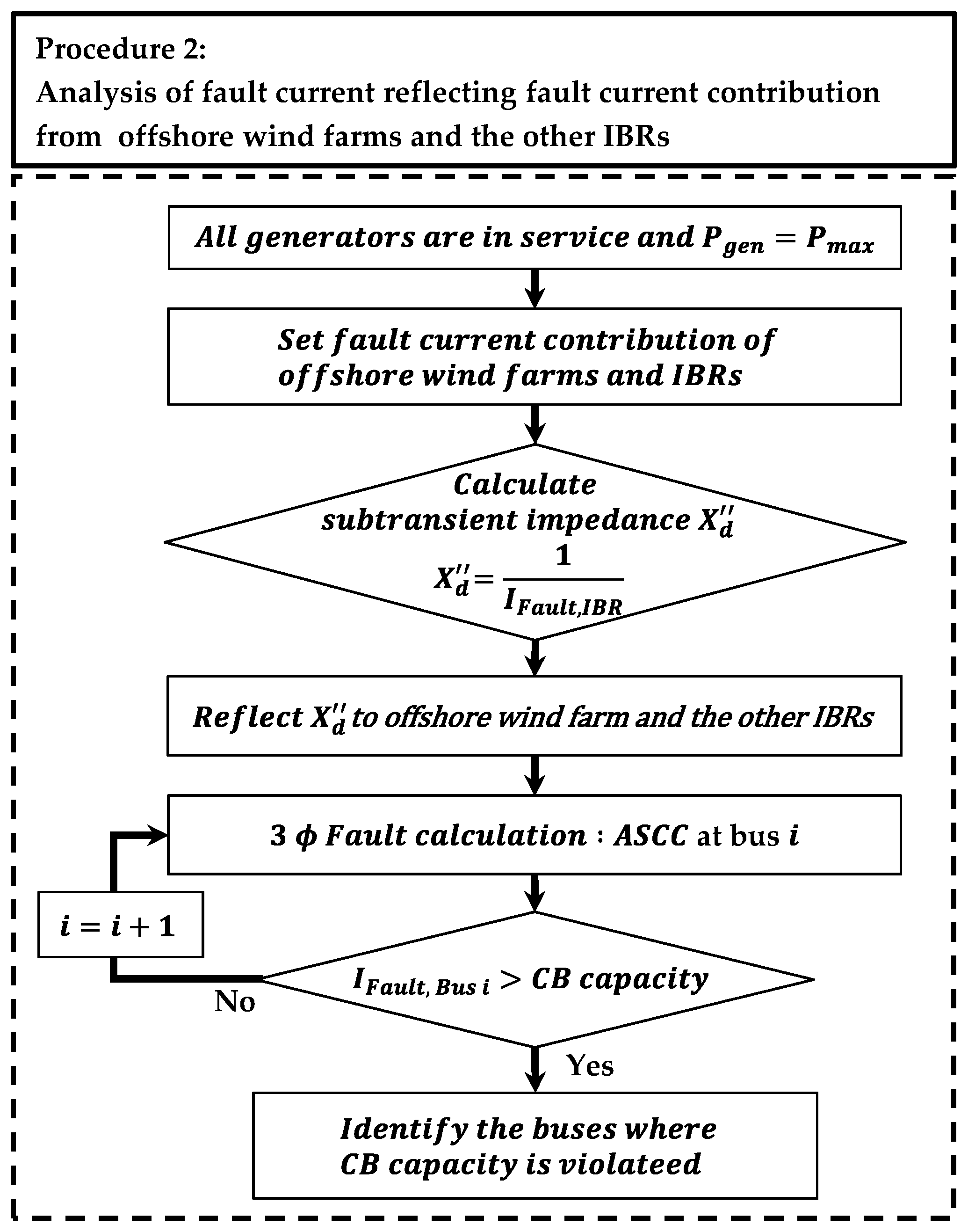
2.1.2. Procedure for Analyzing Fault Current Considering Fault Current Contribution from Offshore Wind Farms and the Other IBRs

The IBRs are modeled as a generator, which is a voltage source with internal impedance in the PSS/E. However, the fault current from the IBRs is limited compared with that from synchronous generators. To reflect the fault characteristics of IBRs, the IBR model needs to be modified to produce the limited amount of fault current.
The subtransient impedance, X d , is typically applied to determine the short circuit current as a generator internal impedance when responses are determined by most transmission system relays [22,23,24]. In the PSS/E, the subtransient impedance is used, along with the generator internal voltage, as input data for fault calculations. Thus, the IBR can be modeled as a constant current source as it produces a short circuit current during the fault. For the fault current from an IBR, the relationship can be described by:
I Fault ,   IBR = V i V f X d
where the I Fault , IBR is the fault current from the IBR, V i is the internal generator voltage, V f is the faulted bus voltage, and X d is the subtransient impedance of the generator. The fault current from the IBR can be changed by adjusting the internal voltage and subtransient impedance of the generator. From an overview of research on short circuit current calculation [25,26,27], several assumptions were made for simplification of the IBR fault current calculation. The internal generator voltage ( V i ) was assumed to be 1.0 pu and the faulted bus voltage ( V f ) was assumed to be zero. This calculation is shown as follows:
I Fault ,   IBR = 1 X d
The fault current from the IBR is inversely proportional to the subtransient impedance of the generator. Furthermore, the fault current characteristics of the IBRs are different, depending on the type of wind plant model and solar photovoltaic (PV) owing to the differences in both the connection to the system and the structure of the IBRs. Type IV wind turbine generators (WTGs) and solar PVs are only connected to the system via inverters. However, Type III WTGs can be directly connected to the system and rotor across a partially rated converter. Therefore, Type IV WTGs and solar PV have a subtransient impedance of 0.833 pu due to the fault current being limited to 1.2 pu of the nominal current. In contrast, Type III WTGs have a subtransient impedance of 0.5 pu due to the fault current limited to 2.0 pu of the nominal current. Thus, procedure 2 for analyzing the fault current reflecting the fault current contribution from offshore wind farms and the other IBRs is described in Figure 2.
The analysis of fault current for determining the circuit breaker capacity is conservatively performed, assuming all the generators are in service and their outputs are at a maximum. In this procedure, assumptions are made by changing the status of all generators to be in-service and adjusting their active power generation to be at a maximum. Next, the subtransient impedance of offshore wind farms and the other IBRs are calculated and modified reflecting their fault current contribution. The three-phase fault calculation at bus i is conducted using the ASCC in the PSS/E to determine whether the fault current violates the limited capacity of the circuit breaker. If the fault current is greater than the circuit breaker capacity, it is identified as a bus requiring an increase of the circuit breaker capacity. Conversely, if the fault current does not exceed the capacity of the circuit breaker, the procedure is repeated for the next bus i + 1 .

2.2. Case Studies

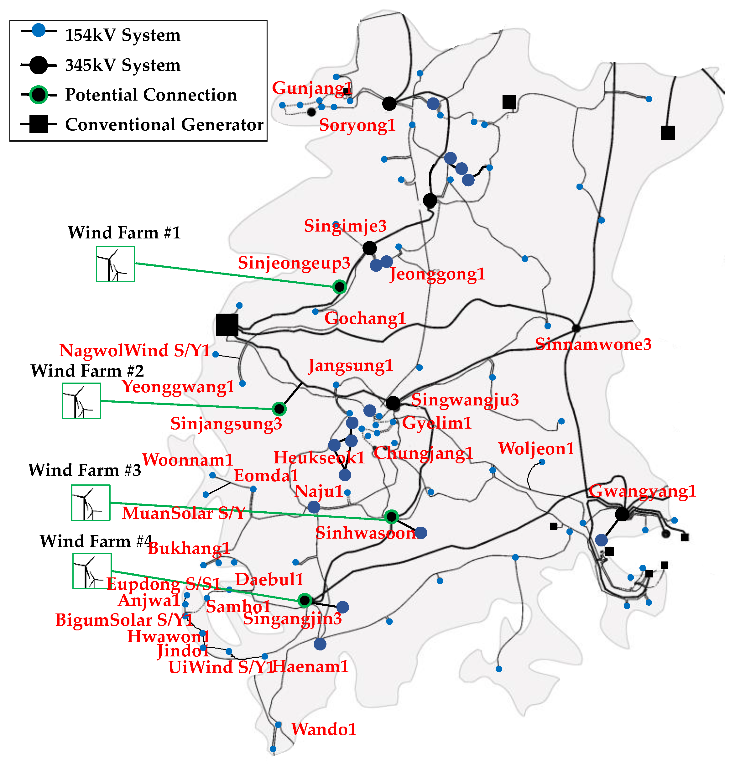
2.2.1. Case Studies in the Southwest Area of the KEPCO System

Potential onshore connection points cover the southwest coast of KEPCO systems, shown in Figure 3. Moreover, according to the regulatory policy of KEPCO, offshore wind farms should be connected to the 345 kV transmission system if offshore wind generation is greater than 1000 MW. In this study, offshore wind generation was greater than 1 GW, and therefore needed to be connected to the planned onshore POIs of the 345 kV transmission system in the southwest KEPCO system.
All offshore wind farms are planned to be installed and operational by 2034. To evaluate the regional impact of offshore wind farms on an area with a high penetration of renewable energy sources, the case studies were conducted in the southwest area of the future KEPCO planning system for 2034, reflecting elements such as the generation plan, and the transmission network configuration, by following the 9th Basic Plan for Long-term Electricity Supply and Demand [28]. The base case for the steady-state analysis is the KEPCO planning system for 2034 without connection of offshore wind farms, and consisting of 18 conventional synchronous machines and 140 renewables (such as WTGs and solar PVs). The total active power generation of the southwest area in the base case was 13,114 MW, out of which 6006 MW was from conventional sources and 7108 MW was from renewables. Cases for steady-state analysis were derived by connection of offshore wind farms of different sizes and locations as planned in [19] and are presented in Table 1. In addition, the penetration level of offshore wind farms for each case was calculated by dividing the offshore wind power generation by the total power generation in the southwest area, which varied from 10.13% for case 1 to 38.10% for case 4.

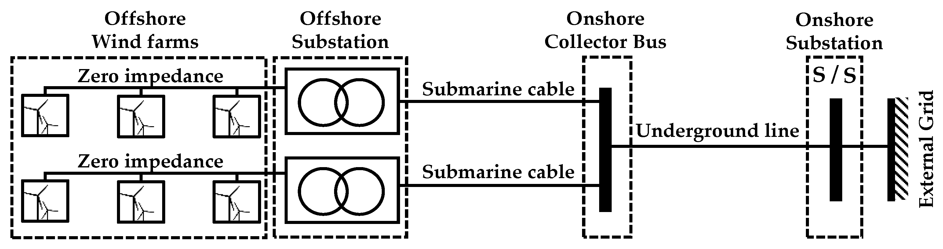
2.2.2. Modeling of Large-Scale Wind Farms Connected via an Onshore Collector Bus

Large-scale wind farms are connected to offshore substations through submarine alternating current (AC) cables, transformed, and connected to the onshore collector bus of the mainland. The basis for steady-state analysis for AC connections is shown in Figure 4. The large offshore wind substations in the southwest area of the KEPCO system share the onshore collector bus. This onshore collector bus is connected to the onshore substations through underground cables. In this study, the offshore wind farms and the line to the mainland were modeled, considering the review conditions for integration of offshore wind farms from KEPCO. The offshore wind farms were modeled using an aggregated model. The AC cables from offshore wind farms to offshore substations were modeled as lines with zero impedance. From the offshore substations to an onshore collector bus, the lines were modeled using the parameters of the submarine cable model XLPE 630. The line from an onshore collector bus to an onshore substation was modeled as an underground line, using the ACSR 480 cable model. The parameters of line models are illustrated in Table 2.

3. Results and Discussion

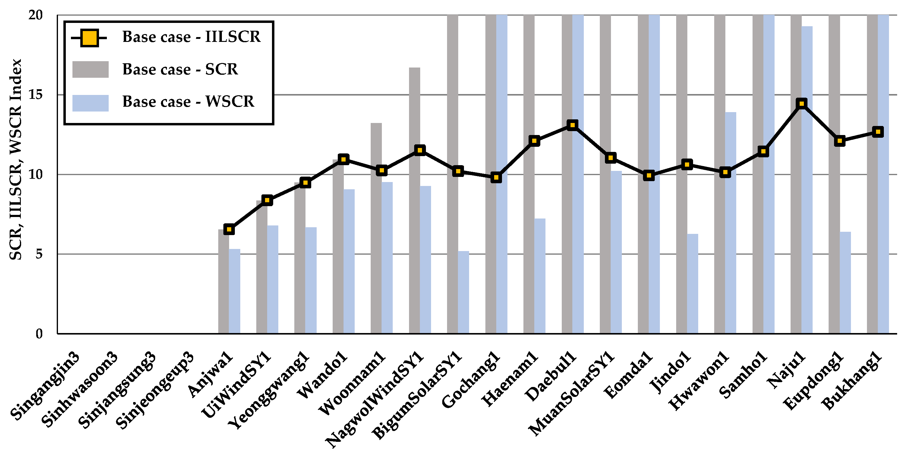
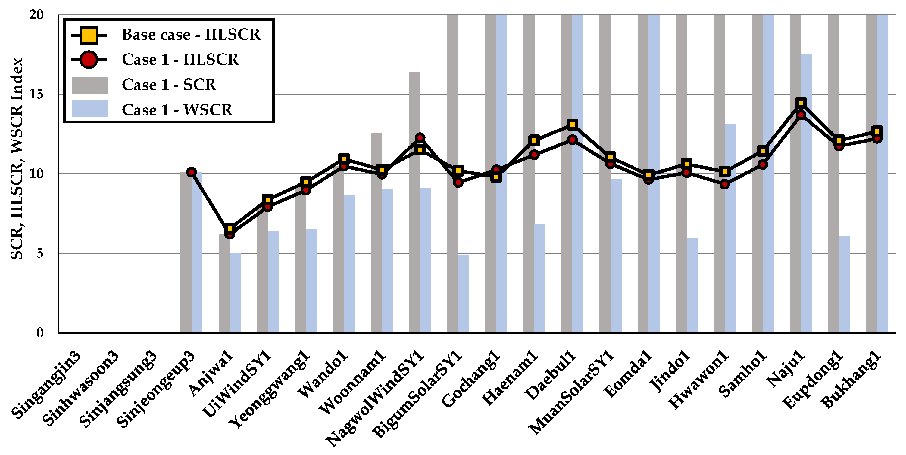
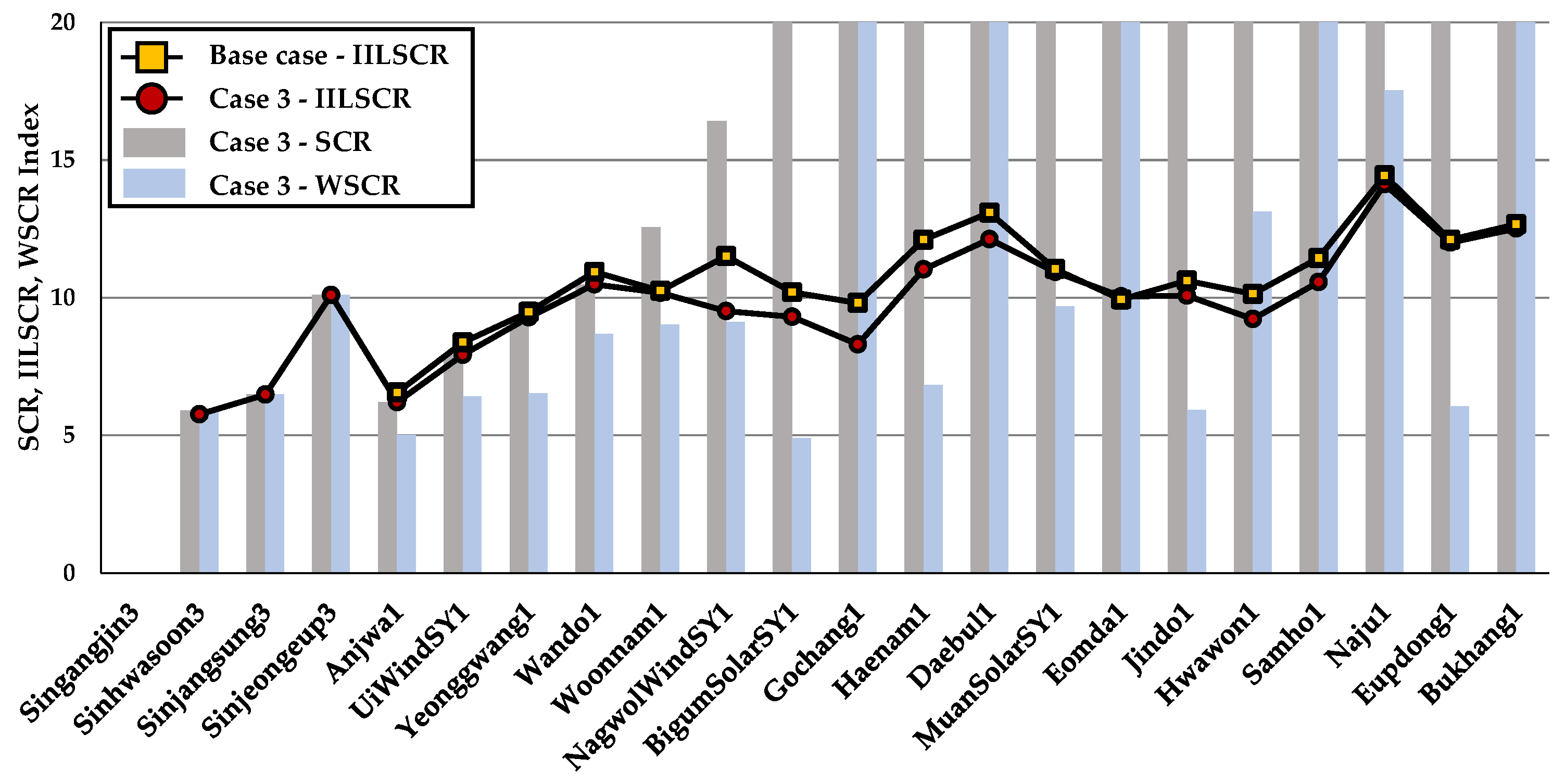
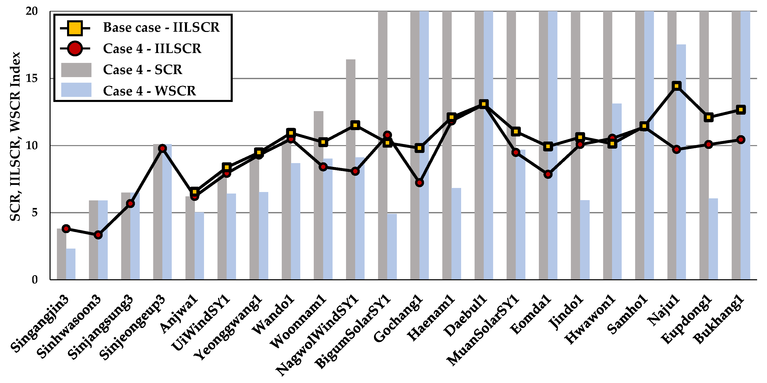
3.1. Assessment of System Strength

The results of the system strength evaluation when offshore wind farms of different sizes and locations are connected to the southwest area of the KEPCO system are presented in Figure 5, Figure 6, Figure 7, Figure 8 and Figure 9. Buses in the figure represent buses with an IILSCR < 20. SCR values of the buses where the IBRs are connected including offshore wind farms were calculated using the SCC before connection of the IBRs; P I B R is the output of each IBR at each bus. The SCC and P I B R are described in Appendix A. The SCC was not changed when the offshore wind farms were connected in each case. The P I B R of each of the buses to which the offshore wind farms were connected can be changed with the offshore wind generation while there was no change in the P I B R of the other buses where the IBRs were connected. Hence, the SCR values of the buses were not changed for each case except for the buses where the offshore wind farms were additionally connected. As the WSCR index was calculated using the SCC of the POI bus before connecting the IBRs and the output IBRs in the same way, the index had the same value if the IBRs were not connected within 1-level from the POI bus.
The IILSCR index of the base case without the offshore wind farms implied that the interaction of the IBRs was only reflected. For the base case, the lowest SCR and IILSCR indices were in the Anjwa1 bus, both at 6.548, and the lowest WSCR was in the BigumSolarSY1 bus at 5.179, which are shown in Figure 5. Some buses have the same value of SCR index as the one of IILSCR, such as Anjwa1, due to no interaction of IBRs. The amount of interaction analyzed by using the power tracing method showed that the IBRs interacted most with the Naju1 bus at 473 MW. However, 14.43 IILSCR index of the Naju1 was the highest as its SCC (7577 MVA) was the highest.
For case 1, offshore wind farm #1 was connected at the Sinjeongeup3, and the SCR, WSCR, and IILSCR indices of the Sinjeongeup3 were evaluated as 10.103. This result is described in Figure 6. Furthermore, the additional installation of offshore wind farm #1 caused the interaction of offshore wind farm #1 and the other IBRs to make the system strength change. The IILSCR indices of some buses, such as NagwolWindSY1 and Gochang1, were lower than the base case due to interactions of offshore wind farm #1 and the other IBRs. This indicated that these buses are getting weaker considering the interaction of offshore wind farm #1 and the other IBRs even though the SCR and WSCR indices were not affected. In addition, the difference in the IILSCR of Daebul1 for case 1 and the base case was the largest as 0.95.
Offshore wind farm #2 was additionally connected to the Sinjangsung3 in case 2, indicating 6.481 for all three indices, illustrated in Figure 7. The system strength evaluation of case 2 found that the 13 buses had lower IILSCR indices compared with the ones of the base case. Furthermore, the difference of IILSCR of Haenam1 between case 2 and base case was the largest as 1.11, which was larger than Daebul1 in case 1. This suggests that additional connection of the offshore wind farms can increase the interaction with the other IBRs, reducing the system strength.
Offshore wind farms #1, #2, together with #3 on the Sinhwasoon3 bus were connected in case 3. Three indices of the Sinhwasoon3 bus were evaluated as 5.906, illustrated in Figure 8. Moreover, 17 buses had lower IILSCR indices than the base case, indicating that the largest difference among them was 2.00 at NagwolWindSY1 in case 3. However, for case 3, all buses were determined as strong buses for three indices of system strength evaluation.
System strength assessment of case 4 showed that 16 buses had lower IILSCR indices than the base case, described in Figure 9. The largest difference among the buses was 4.73 at Naju1, which is approximately twice NagwolWindSY1 in case 3. Moreover, for case 4, the SCR and IILSCR indices of the Singangjin3 were evaluated as 3.798, which were determined as moderate buses. Sinhwasoon3 was also determined as 3.34 of IILSCR, which is a moderate bus. However, Sinhwasoon3 was examined as a strong bus in the SCR index of 5.91. In addition, the lowest WSCR index at 2.318 was for the Singangjin3 bus, which indicated that the bus is strong.
System strength evaluation considering the interaction of offshore wind farms and the other IBRs indicated that two buses with an IILSCR < 5 in the southwest area were determined as moderate buses in case 4. However, for case 4, the SCR index, not considering interactions, indicated that all buses were determined as moderate buses. The system strength evaluated by the WSCR index in the southwest area was strong for all cases. The interaction of offshore wind farms should be reflected to evaluate the exact system strength for the connection of large-scale offshore wind farms.

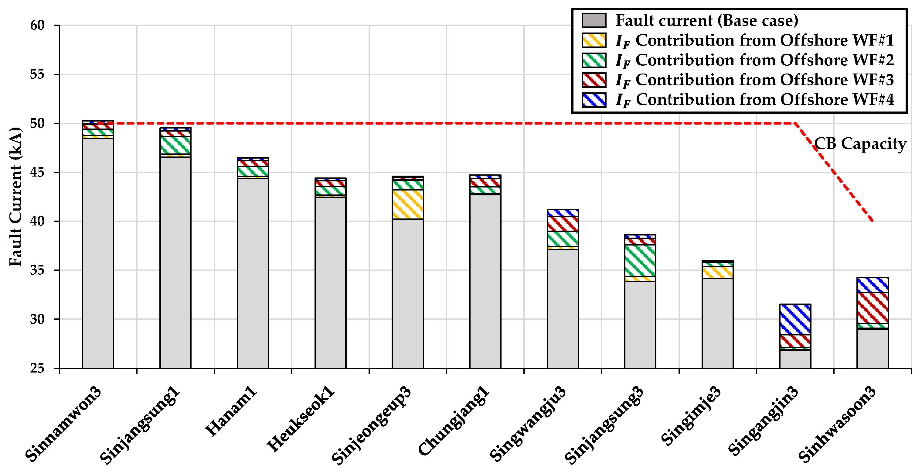
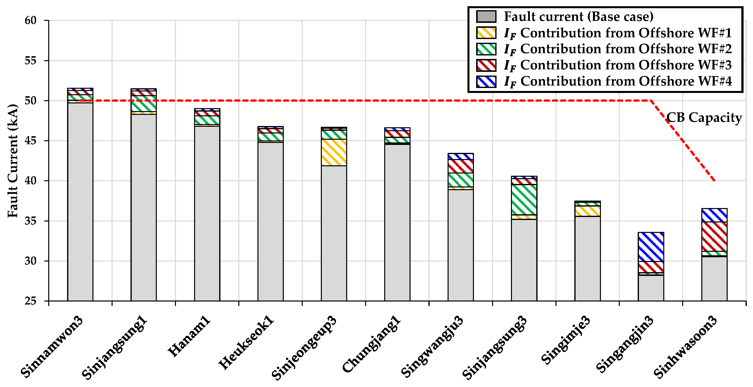
3.2. Analysis of Fault Current

Fault currents of the buses in the southwest area of the KEPCO system were analyzed using procedure 2 described earlier, setting the fault current from offshore wind farms and the other IBRs to 1.2 pu and 2.0 pu of nominal current, respectively, to consider both a conservative and optimistic view. The buses where the total fault current contributions from offshore wind farms were greater than 1 kA are shown in Figure 10. The fault current of the base case comprised synchronous generators and the other IBRs in the southwest area of the KEPCO system, indicating the largest fault current was 48.45 kA, of Sinnamwon3, and the smallest fault current was 26.82 kA, of Singangjin3. Thus, the base case with no connection of offshore wind farms showed that there were no buses where the circuit breaker capacity was exceeded.
The highest fault current contribution was at Sinjeongeup3 at 2.96 kA owing to the connection of offshore wind #1 in case 1. The total fault current at Sinjeongeup3 increased from 40.22 kA to 43.19 kA and was less than the circuit breaker capacity. The lowest fault current contribution for case 1 was 0.056 kA of Singangjin3 as this bus is connected four levels away from the POI of offshore wind farm #1. For case 2, offshore wind farm #2 was additionally installed at Sinjangsung3 to case 1. The highest fault current contribution of offshore wind farm #2 was 3.22 kA at Sinjangsung3 where the offshore wind farm #2 was connected in case 2. The lowest contribution of fault current for case 2 at 0.25 kA was at Singangjin3, owing to Singangjin3 being connected three levels away from Sinjangsung3. The total fault current contributions by offshore wind farms for case 2 indicated a maximum value of 3.99 kA at Sinjeongeup3 and a minimum value of 0.31 kA at Singangjin3. The maximum fault current contribution from offshore wind farm #3 was 3.13 kA at Sinhwasoon3 in case 3. In addition, the lowest contribution at 0.11 kA was at Singimje3, owing to Singimje3 being connected four levels away from Sinhwasoon3. Conversely, the total fault current contribution by three offshore wind farms indicated a maximum value of 4.44 kA at Sinjangsung3 and a minimum value of 1.45 kA at Sinnamwon3. Case 4 had all the offshore wind farms connected. The largest fault current contribution at 3.12 kA in case 4 was at Singangjin3 due to the connection of offshore wind farm #4. Conversely, the total fault current contribution by all offshore wind farms was highest at 5.28 kA at Sinhwasoon3 with no exceeding of the circuit breaker capacity. However, the fault current at Sinnamwon3 was increased from 49.91 kA for case 3 to 50.23 kA for case 4 due to the connection of offshore wind farm #4, exceeding the circuit breaker capacity of 50 kA.
Analysis of fault current contributions from offshore wind farms was performed when fault current of offshore wind farms and the other IBRs were set to 2.0 pu, as shown in Figure 11. Fault currents of the base case at the buses in Figure 11 were increased when fault current of the other IBRs was set to 2.0 pu from 1.2 pu. Each case had the same network topology with the fault current contributions changing as the fault current of offshore wind farms and the other IBRs were varied. The buses where the fault current contributions from offshore wind farms were maximized were identical for each case. However, the fault current of Sinnamwon3 exceeded the circuit breaker capacity for case 1 due to the connection of offshore wind farm #1, and the fault current at Sinjangsung1 for case 2 also exceeded the circuit breaker capacity of 50 kA owing to the fault current contribution from the offshore wind farm #2.
Fault currents of the buses in the southwest area did not exceed the circuit breakers capacity if the fault current contributions from offshore wind farms were not considered for analysis of fault current. However, the results of fault current analysis in Figure 10 and Figure 11 show that the fault current of the buses can violate the capacity limit of the existing circuit breakers considering fault current contribution from large-scale offshore wind farms, varying from 1.2 pu to 2.0 pu. This implies that the reflection of fault current contribution from offshore wind farms should be required to analyze the fault current for connection of large-scale offshore wind farms.

4. Conclusions

This study described the grid connection investigations for large-scale offshore wind farms in an area with high penetration of renewables. The system strength was evaluated by considering the interaction of large-scale offshore wind farms and IBRs. Then, the fault current was analyzed to determine the contribution of offshore wind farms and other IBRs.
The case studies based on the southwest area of the KEPCO system with high levels of renewables have potential POIs for large-scale offshore wind farms. The first results showed that the consideration of the actual interaction of offshore wind farms and other IBRs is necessary to perform an accurate assessment of the system strength for the connection of large-scale offshore wind farms. The second result showed that the fault current contribution from offshore wind farms and the other IBRs should be reflected to analyze fault current accurately for the connection of large-scale offshore wind farms in areas with a high penetration of renewable energy sources. Therefore, the proposed grid connection studies could serve as a guideline for power system planners to understand the factors to consider when integrating large-scale wind farms in areas with high penetration of renewables.

Author Contributions

N.C. conceived and designed the research methodology, improved the system simulation, and wrote the paper; B.K. performed the system simulations, made suggestions regarding the research, and wrote the paper; B.L. supervised the research, improved the system simulation, and made suggestions regarding the research; and D.K., S.K. and B.P. contributed to the writing of the paper. All authors have read and agreed to the published version of the manuscript.

Funding

This work was supported by the National Research Foundation of Korea (NRF) grant funded by the Korea government (MSIT) (NRF-2021R1A2C2006511) and supported by the Basic Research Program through the National Research Foundation of Korea (NRF) funded by the MSIT (No. 2020R1A4A1019405).

Institutional Review Board Statement

Not applicable.

Informed Consent Statement

Not applicable.

Data Availability Statement

Not applicable.

Acknowledgments

There were no additional contributions made to this study other than those of the authors and the funding stated above.

Conflicts of Interest

The authors declare no conflict of interest.

Appendix A

Table A1. Short-circuit capacity at the buses and active power generation from offshore wind farms and IBRs.
BusShort-Circuit Capacity (MVA)IBR Generation (MW)
Sinjeongeup318,6191680 (Offshore wind farm #1)
Sinjangsung315,8312450 (Offshore wind farm #2)
Sinhwasoon312,3922100 (Offshore wind farm #3)
Singangjin311,1592940 (Offshore wind farm #4)
Anjwa13245495
UiWindSY13188380
Yeonggwang12498263
Wando12530231
Woonnam13324251
NagwolWindSY12487149
BigumSolarSY13556115
Gochang1343181
Haenam1411183
Daebul1460165
MuanSolarSY1332640
Eomda1372338
Jindo1313328
Hwawon1385331
Samho1406133
Naju1757751
Eupdong1323511
Bukhang135865

References

  1. Milano, F.; Dörfler, F.; Hug, G.; Hill, D.; Verbic, G. Foundations and Challenges of Low-Inertia Systems. In Proceedings of the Power Systems Computation Conference (PSCC), Dublin, Ireland, 11–15 June 2018; pp. 1–25. [Google Scholar]
  2. Elliott, D.; Bell, K.R.; Finney, S.J.; Adapa, R.; Brozio, C.; Yu, J.; Hussain, K. A Comparison of AC and HVDC Options for the Connection of Offshore Wind Generation in Great Britain. IEEE Trans. Power Deliv. 2016, 31, 798–809. [Google Scholar] [CrossRef] [Green Version]
  3. Chang, Z.; Wang, X.; Wei, Z.; Lu, G.; Lu, J.; Huang, Y.; Gao, K.; Li, T.; Tang, J. Analysis of influence of large-scale wind farm grid connection on system short-circuit current. In Proceedings of the 2019 4th IEEE Workshop on the Electronic Grid (eGRID), Xiamen, China, 11–14 November 2019; pp. 1–6. [Google Scholar] [CrossRef]
  4. Du, W.; Dong, W.; Wang, H.; Cao, J. Dynamic Aggregation of Same Wind Turbine Generators in Parallel Connection for Studying Oscillation Stability of a Wind Farm. IEEE Trans. Power Syst. 2019, 34, 4694–4705. [Google Scholar] [CrossRef]
  5. Melis, U.; Şener, Z. Suitable map analysis for wind energy projects using remote sensing and GIS: A case study in Turkey. Environ. Monit. Assess. 2019, 191, 459. [Google Scholar]
  6. Kundur, P. Power System Stability and Control; McGraw-Hill Inc.: New York, NY, USA, 1994; pp. 105–127. [Google Scholar]
  7. IEEE Guide for Planning DC Links Terminating at AC Locations Having Low Short-Circuit Capacities; IEEE Std 1204-1997; IEEE SA Standards Board: New York, NY, USA, 1997; pp. 1–216. [CrossRef]
  8. Huang, S.H.; Schmall, J.; Conto, J.; Adams, J.; Zhang, Y.; Carter, C. Voltage control challenges on weak grids with high penetration of wind generation: ERCOT experience. In Proceedings of the 2012 IEEE Power and Energy Society General Meeting, San Diego, CA, USA, 22–26 July 2012; pp. 1–7. [Google Scholar] [CrossRef]
  9. Zhang, Y.; Huang, S.H.F.; Schmall, J.; Conto, J.; Billo, J.; Rehman, E. Evaluating system strength for large-scale wind plant integration. In Proceedings of the 2014 IEEE PES General Meeting|Conference & Exposition, National Harbor, MD, USA, 27–31 July 2014; pp. 1–5. [Google Scholar] [CrossRef]
  10. Huang, F. Experience with WTG weak system interactions on the ERCOT system. In Proceedings of the 2015 IEEE Power & Energy Society General Meeting, Denver, CO, USA, 26–30 July 2015; pp. 16–30. [Google Scholar]
  11. Choi, N.; Lee, B.; Kim, D.; Nam, S. Interaction boundary determination of renewable energy sources to estimate system strength using the power flow tracing strategy. Sustainability 2021, 13, 1569. [Google Scholar] [CrossRef]
  12. Baran, M.E.; El-Markaby, I. Fault analysis on distribution feeders with distributed generators. IEEE Trans. Power Syst. 2005, 20, 1757–1764. [Google Scholar] [CrossRef]
  13. Simic, N.; Strezoski, L.; Dumnic, B. Short-circuit analysis of DER-based microgrids in connected and islanded modes of operation. Energies 2021, 14, 6372. [Google Scholar] [CrossRef]
  14. Chu, Z.; Teng, F. Short-circuit current constrained UC in High IBG-Penetrated Power Systems. IEEE Trans. Power Syst. 2021, 36, 3776–3785. [Google Scholar] [CrossRef]
  15. Choi, N.; Park, B.; Cho, H.; Lee, B. Impact of momentary cessation voltage level in inverter-based resources on Increasing the short-circuit current. Sustainability 2019, 11, 1153. [Google Scholar] [CrossRef] [Green Version]
  16. Barker, P.; DeMello, R. Determining the impact of DG on power systems, radial distribution. In Proceedings of the 2000 Power Engineering Society Summer Meeting (Cat. No.00CH37134), Seattle, WA, USA, 16–20 July 2000; Volume 3, pp. 1645–1656. [Google Scholar]
  17. Keller, J.; Kroposki, B.D. Understanding Fault Characteristics of Inverter-Based Distributed Energy Resources. 2010. Available online: http://research.iaun.ac.ir/pd/bahador.fani/pdfs/UploadFile_9423.pdf (accessed on 16 November 2018).
  18. Kim, D.; Cho, H.; Park, B.; Lee, B. Evaluating influence of inverter-based resources on system strength considering inverter interaction level. Sustainability 2020, 12, 3469. [Google Scholar] [CrossRef] [Green Version]
  19. Ministry of Trade, Industry & Energy(MOTIE) of the Republic of Korea. Offshore Wind Power Generation Plan to Coexist with Residents and to Coexist with the Fishery Industry. 19 July 2020. Available online: http://www.motie.go.kr/motie/gov3.0/gov_openinfo/sajun/bbs/bbsView.do?bbs_seq_n=163153&bbs_cd_n=81 (accessed on 1 December 2021).
  20. Bialek, J. Tracing the flow of electricity. IEE Proc.-Gener. Transm. Distrib. 1996, 143, 313–320. [Google Scholar] [CrossRef] [Green Version]
  21. Park, S.; Jin, H.; Kim, H.; Cho, Y. A Study on Future System Construction Using WSCR Strengthness Index Based on Python. 2018. Available online: http://www.dbpia.co.kr/journal/articleDetail?nodeId=NODE07511879 (accessed on 1 August 2018).
  22. Liu, S.; Bi, T.; Liu, Y. Theoretical analysis on the short-circuit current of inverter-interfaced renewable energy generators with fault-ride-through capability. Sustainability 2018, 10, 44. [Google Scholar] [CrossRef] [Green Version]
  23. Kennedy, J.; Ciufo, P.; Agalgaonkar, A. Fault approximation tool for grid-connected inverter-interfaced distributed generators. In Proceedings of the 2014 Australasian Universities Power Engineering Conference (AUPEC), Perth, Australia, 28 September–1 October 2014. [Google Scholar] [CrossRef] [Green Version]
  24. Brucoli, M.; Green, T.C.; McDonald, J.D.F. Modelling and analysis of fault behaviour of inverter microgrids to aid future fault detection. In Proceedings of the 2007 IEEE International Conference on System of Systems Engineering, San Antonio, TX, USA, 16–18 April 2007; pp. 1–6. [Google Scholar] [CrossRef]
  25. Boutsika, T.N.; Papathanassiou, S.A. Short-circuit calculations in networks with distributed generation. Electr. Power Syst. Res. 2008, 78, 1181–1191. [Google Scholar] [CrossRef]
  26. El-Naggar, A.; Erlich, I. Fault current contribution analysis of doubly fed induction generator-based wind turbines. IEEE Trans. Energy Convers. 2015, 30, 874–882. [Google Scholar] [CrossRef]
  27. Walling, R.; Harley, R.; Miller, D.; Henneberg, G.; Barsch, J.; Bartok, J.; Benmouyal, G.; Bolado, O.; Boysen, B.; Brahms, S.; et al. Fault current contributions from wind plants. In Proceedings of the 2015 68th Annual Conference for Protective Relay Engineers, College Station, TX, USA, 30 March–2 April 2015; pp. 137–227. [Google Scholar] [CrossRef]
  28. Ministry of Trade, Industry & Energy (MOTIE) of the Republic of Korea. The 9th Basic Plan for Long-term Electricity Supply and Demand. 28 December 2020. Available online: https://www.motie.go.kr/motie/py/td/tdtotal/bbs/bbsView.do?bbs_cd_n=72&bbs_seq_n=210325 (accessed on 1 December 2021).
Figure 1. Process for assessment of system strength considering interaction of offshore wind farms and other IBRs.
Sustainability 14 01015 g001
Figure 2. Process for analysis of fault current reflecting fault characteristics of offshore wind farms and other IBRs.
Sustainability 14 01015 g002
Figure 3. Future system configuration of the southwest area by the KEPCO planning system for 2034.
Sustainability 14 01015 g003
Figure 4. Configuration of offshore wind farms connected to the 345 kV transmission system of the mainland.
Sustainability 14 01015 g004
Figure 5. Base case comparison of SCR, WSCR, and IILSCR indices of southwest area.
Sustainability 14 01015 g005
Figure 6. Comparison of SCR, WSCR, and IILSCR indices for case 1 with the base case IILSCR index.
Sustainability 14 01015 g006
Figure 7. Comparison of SCR, WSCR, and IILSCR indices for case 2 with the base case IILSCR index.
Sustainability 14 01015 g007
Figure 8. Comparison of SCR, WSCR, and IILSCR indices for case 3 with the base case IILSCR index.
Sustainability 14 01015 g008
Figure 9. Comparison of SCR, WSCR, and IILSCR indices for case 4 with the base case IILSCR index.
Sustainability 14 01015 g009
Figure 10. Buses where the total fault current contributions of offshore wind farms >1 kA, setting the fault current of offshore wind farms and the other IBRs to 1.2 pu.
Sustainability 14 01015 g010
Figure 11. Buses where the total fault current contributions of offshore wind farms >1 kA when fault current of offshore wind farms and the other IBRs are set to 2.0 pu.
Sustainability 14 01015 g011
Table 1. Active power generation and penetration level of offshore wind farms for each case.
Offshore Wind FarmsPoint of
Connection
Offshore Wind Generation
Base CaseCase 1Case 2Case 3Case 4
Wind Farm #1 (MW)Sinjeongeup301680168016801680
Wind Farm #2 (MW)Sinjangsung300245024502450
Wind Farm #3 (MW)Sinhwasoon300021002100
Wind Farm #4 (MW)Singangjin300002940
Total Offshore Wind Gen. (MW)-1680413062309170
Penetration Level of Offshore Wind (%)-10.1321.7029.4838.10
Table 2. Parameters of lines for different types and length of cables.
TypeResistance
(%/km)
Reactance
(%/km)
Admittance
(%/km)
Wind Farm
#1 (km)
Wind Farm
#2 (km)
Wind Farm
#3 (km)
Wind Farm
#4 (km)
XLPE 6300.0205400.0055010.00001330303030
ACSR 4800.0029000.0308000.52490032815355
Publisher’s Note: MDPI stays neutral with regard to jurisdictional claims in published maps and institutional affiliations.

