Article

CO2 Storage and Geothermal Extraction Technology for Deep Coal Mine

1
School of Mines, China University of Mining and Technology, Xuzhou 221116, China
2
State Key Laboratory of Coal Resources and Mine Safety, China University of Mining and Technology, Xuzhou 221116, China
3
School of Sun Yueqi, China University of Mining and Technology, Xuzhou 221116, China
*
Author to whom correspondence should be addressed.
Sustainability 2022, 14(19), 12322; https://doi.org/10.3390/su141912322
Submission received: 14 July 2022 / Revised: 22 September 2022 / Accepted: 23 September 2022 / Published: 28 September 2022

Abstract

:
This paper aims at reducing greenhouse gas emissions, which contributes to carbon neutrality, and, at the same time, preventing mine heat disasters and extracting highly mineralized (HM) mine water, so as to realize the synergy between CO2 storage (CS) and geothermal extraction and utilization (GEU) in a high temperature (HT) goaf. With this purpose, an innovative CS-GEU technology for HT and HM water in deep mine is proposed, based on the mechanism of water-rock-CO2 effect (WRCE) and the principle of GEU in the mine. This technology uses GEU to offset the costs of CO2 storage and refrigeration in HT mine. A general scheme for a synergistic system of CS and GEU in the goaf is designed. The feasibility of CS-GEU technology in the deep goaf is demonstrated from the views of CS and GEU in the goaf and the principles of a synergistic system. It is clarified that the CO2 migration-storage evolution and the multi-field coupling principle in the goaf are the key scientific issues in realizing the synergic operation of CS and GEU. It proposes the key techniques involved in this process: CO2 capture and CO2 transportation, layout and support of drill holes and high-pressure (HP) pipelines, and HP sealing in the goaf. The research results provide new ideas for CS and GEU of HT and HM mine water in deep mine.

1. Introduction

China is committed to peaking its carbon emissions and controlling its greenhouse gas emissions by 2030 and strives to achieve carbon neutrality by 2060 [1]. Carbon peaking and carbon neutrality reflect China’s responsibility of controlling greenhouse gas emissions as a major country, and represent a significant opportunity for China’s industries to achieve green and low-carbon transformation [2]. Achieving carbon neutrality marks the end of the traditional industrial era and an important turning point in the transformation of an economic development mode. However, China is currently in a stage of rapid industrialization and urbanization, with a huge demand for energy. China’s socio-economic development is mainly driven by coal, and fossil fuels account for 85% of the total amount of energy. We are confronted with many challenges in the transformation of traditional industries and enormous pressure for emission reduction in industrial power generation [3,4,5]. To achieve the ambitious goal of carbon neutrality in the process of socio-economic development, solutions such as reducing carbon emissions and increasing carbon sinks have been put forward. From the perspective of China’s energy structure, carbon storage and other carbon negative emission technologies are effective technical approaches. Carbon capture and carbon storage technologies become key scientific and technological issues [6,7,8,9,10]. See Figure 1.
After longwall mining in the coal seam, the overlying rock strata (RS) in the goaf collapse, and the rock fractures, break through the overlying aquifer. Thus, the goaf is filled with water, causing changes to the local hydrogeological characteristics [11]. During this period, a series of water-rock and water-coal reactions occur such as evaporation and concentration, dissociative adsorption, solution and precipitation, redox, ion exchange, chemical degradation, etc. These reactions will produce HM mine water in some areas [12,13,14,15,16,17]. The treatment of such mine water requires a large amount of costs. In the mines in central and eastern China and new mines in western China, the coal resources at a buried depth of over 1000 m account for more than 50% [18,19]. With the increase in mining depth, ground temperature gradually increases. The temperature on the surrounding rock at a depth of 1000 m in most mines of China can reach 35–45 °C [20]. Therefore, mine heat disasters will cause great harm to underground workers, and huge funds should be invested in mine cooling. There is a huge underground space in the goaf of a coal mine. Usually, the advancing length can reach 4–5 km, the strike length can reach 400 m, the height of the vertical caving zone and fracturing zone can reach 60 m, and the water storage coefficient is about 0.4 [21]. Therefore, the porous rock mass in the goaf can store a large amount of HM mine water and geothermal resources. Mine geothermal and water, as the intergrowth and associated resources of coal measures, occur in a wide range and are stably supplied. If disasters are regarded as resources for rational development and utilization, production and operation costs can be greatly reduced.
By injecting HP CO2 into the goaf, CO2 can be stored in the sealed mine goaf. At the same time, HT mine water is pumped to extract geothermal and water resources from the goaf, which is regarded as a heat and water reservoir. This provides stable and sustainable geothermal energy and water supply for the surrounding buildings, and reduces the cost of mine cooling and CO2 storage technology. In addition, as CO2 softens HM water, the cost of water purification can be reduced. The deep mine goaf is used to achieve CO2 storage, mine water purification, and mine geothermal extraction. With this technology, the intergrowth and associated resources of coal measures and abandoned underground space in the mine can be fully and effectively utilized. Scholars have made research on CS in coal mine. Wang SM et al. discussed the various conditions of CS in the coal mining area, and proposed relevant technologies of CS in the mining goaf and coal seam gasification cavity [22]. Liu L et al. proposed the academic conception of the CS method based on functional backfilling, and formed the theoretical and technical conception of using the solid waste backfilling technology to realize mine CS [23]. Roddy, D. J et al. reviewed key developments in technologies for underground coal gasification (UCG), Carbon Capture and Storage (CCS) and CS in coal seam voids and quantified the scale of the opportunity that these technologies open up [24].
In this paper, we provide an innovative technology of CO2 storage and geothermal extraction for HT and HM mine water in deep mines based on coal mining practices, and propose the concrete system scheme of the technology. The feasibility of the process is demonstrated, and the scientific issue of CS-GEU system is explained. In addition, we put forward the key technologies involved in the CO2 storage process, so as to explore new means and technologies for CCS and give guidance to the use of underground reservoirs in the goaf to achieve CO2 storage.

2. General Scheme

The synergic operation of CS and GEU in the goaf is realized by integrating geothermal mining technology, CO2 storage technology and mining practice. The goaf is used as a heat reservoir to achieve CO2 storage and the extraction and utilization of mine geothermal resources. The general scheme is shown in Figure 2.
First of all, the CO2 gas produced after or during coal combustion in power plants was captured and then purified. CO2 was purified through the transportation by a series of HP pipelines, which were laid to the adjacent air shaft industrial plant of the deep mine. An HP CO2 storage tank was installed in the air shaft industrial plant to store some CO2 as a buffer. The CO2 was delivered to the opposite direction of the air shaft, so that the CO2 could be discharged along with the return air flow, to prevent accidents caused by CO2 leakage in the mine. A chamber was set up near the goaf to store the CO2 supercritical preparation equipment, which prepared supercritical CO2. The CO2 was delivered to the above-mentioned chamber through a series of tunnels, and was compressed to a supercritical state ready for injection under a pressure of 7 MPa and at a temperature of 33.1 °C.
The goaf was sealed and made HP resistant in advance. The overlying RS fractures, artificial dam joints, coal pillar dam fractures and water seepage places were sealed by spraying slurry and injecting gel. The goaf and its overlying structure must be well sealed. An HP pipeline leading into the goaf was arranged, through which the prepared supercritical CO2 was transported into the goaf. The mine water in the goaf was mixed with supercritical CO2, causing a series of reactions to produce carbonic acid precipitation. The CO2 was in full contact with the fractured rocks, causing a series of WRCE to produce new carbonic acid minerals, and thus CO2 was stored in the goaf.
Geothermal extraction was conducted on the other side of the goaf. Multiple rows of pumping holes leading into the goaf were set up at the mining level. Insulating water-transporting pipelines were arranged, and pumps were used to extract HT mine water under a constant pressure. Hot water was lifted to the surface industrial plant through the main shaft. The surface plant was equipped with a water source heat pump system, consisting of gas-liquid separation equipment, water source heat pump units, filters and other equipment. Firstly, gas-liquid separation treatment was conducted on the extracted hot water to separate CO2 from it, and then the heat pump system was used to extract heat energy from the water. Heat exchange was made with the closed-loop system in the residential area. This would support the heating and bathing of the residents in and surrounding the mine area. The collected CO2 could be reinjected into the extraction area through pipelines. After heat extraction, the mine water could be reinjected into the overlying aquifer of the goaf, which would reduce the sedimentation of the aquifer. Intermittent heat extraction can be adopted as the geothermal mining mode in the goaf. The extracted flow can be reduced when the mine water is at a low temperature, and increased when the heat is replenished in the goaf and the temperature of mine water recovers. This can extend the life of heat extraction in the goaf, improve the quality of heat extraction, and realize the continuous extraction of geothermal energy.

3. Feasibility of CS-GEU Technology

Using the HT mine goaf to store CO2 and extract geothermal resources involves theoretical technologies such as mine geothermal resource development, WRCE in mine goaf, and goaf sealing. The authors investigated the feasibility of CS and geothermal extraction in the HT mine goaf based on the existing research results.

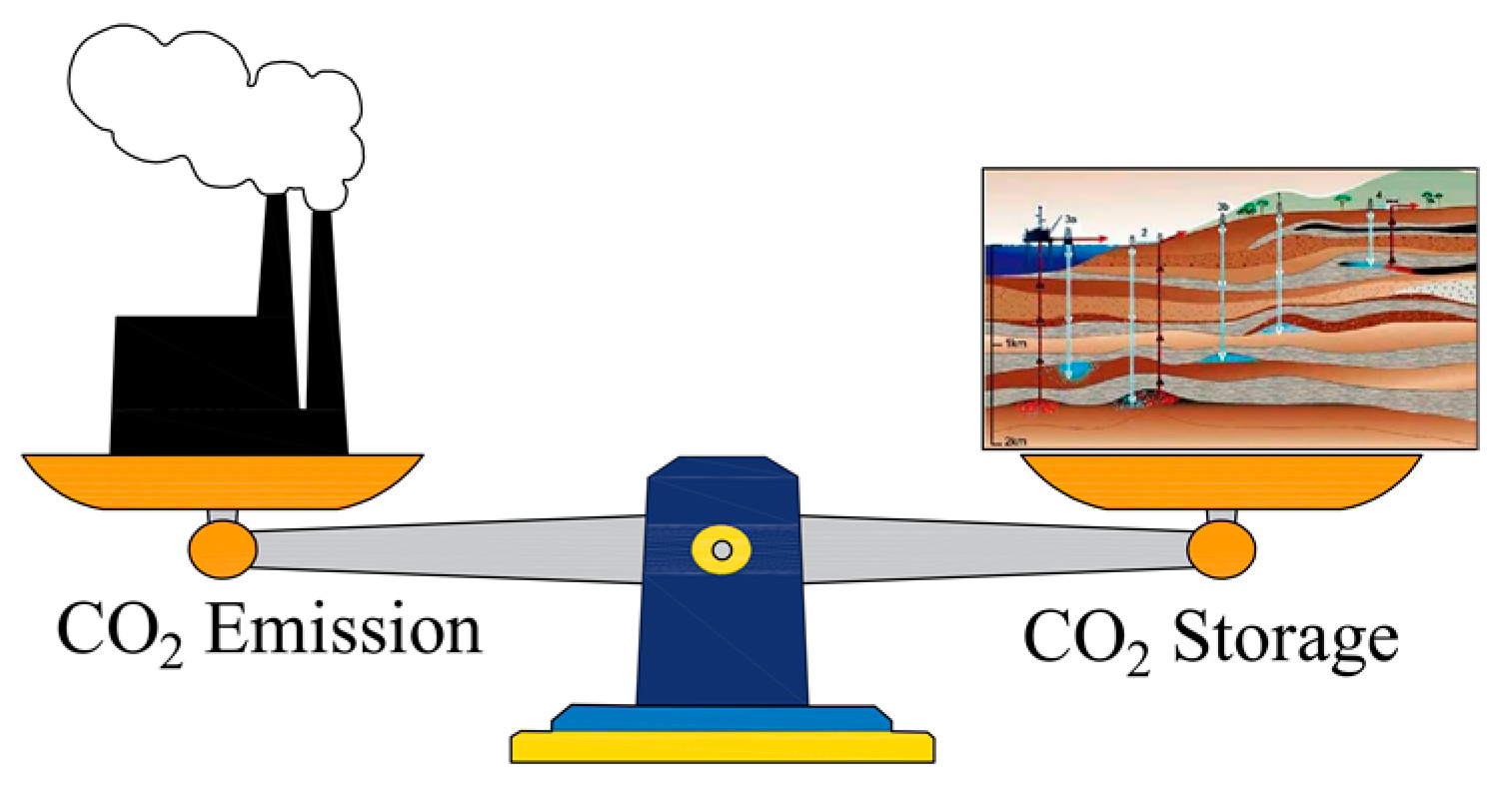
3.1. CS in Mine Goaf
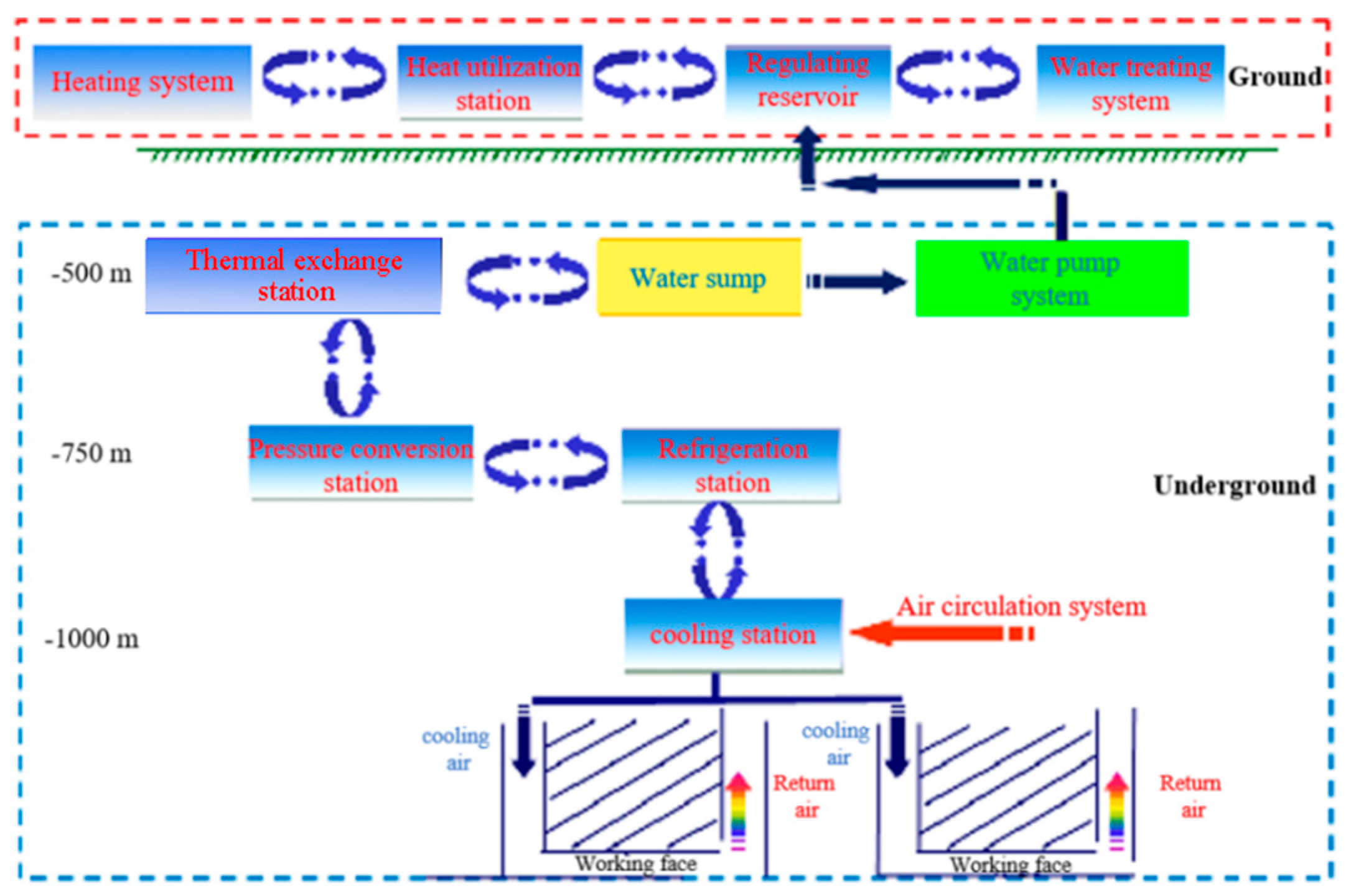
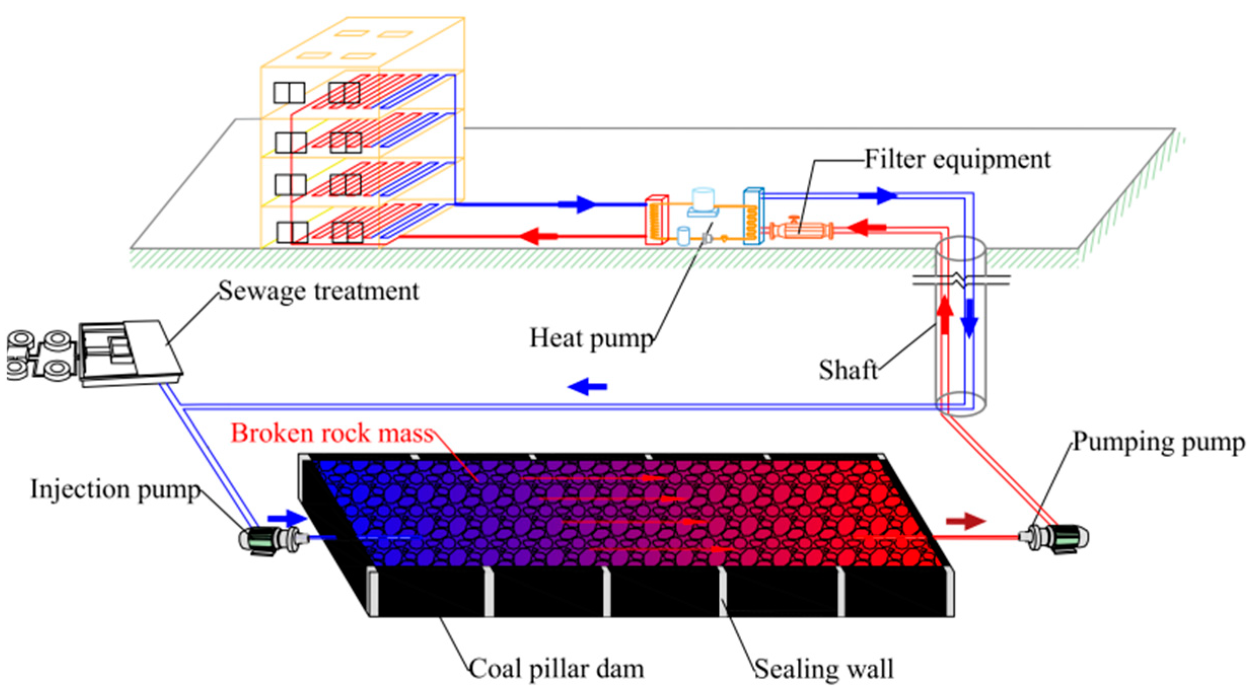
(1) Mineral storage
Due to the water-rock lixiviation, precipitation, and adsorption in the goaf, the dissolution of the fractured rocks in the goaf produces HM ions, which further intensifies the mineralization of mine water [25,26,27,28].
Jin Yuqi [29] conducted the X-ray diffraction test to analyze the mineral composition of a landslide in Zezhou, Jincheng City, Shanxi Province, and found a large number of montmorillonite minerals in the coal measure strata. Zheng Qiming et al. [30] conducted mineralogical research on the gangue and floor of No. 9 coal seam in Jincheng Prefecture, Shanxi through X-ray diffraction analysis and Fourier infrared spectroscopy. It was found that the main clay minerals in the gangue and floor were ammonium illite/montmorillonite interlayer, illite/montmorillonite interlayer, kaolinite, and sodium mica, with a small amount of illite. This indicates that a large amount of clay minerals are stored in the coal mine goaf of some regions in China.
In the above tests and experiments, the rock minerals underwent a water–rock interaction, in which the rocks were dissolved and oxidized, and a large amount of Ca2+, Mg2+, Si4+, and Fe2+ ions were produced, as shown in Equations (1)–(5):
CaCO 3 ( Calcite ) Ca 2 + ( aq ) + CO 3 2 ( aq )
Ca 0.165 Al 2.33 Si 3.67 O 10 ( OH ) 2 ( Montmorillonite ) + 12 H 2 O ( l ) 0.165 Ca 2 + ( aq ) + 2.33 Al ( OH ) 4 ( aq ) + 3.67 H 4 SiO 4 ( s ) + 2 H + ( aq )  
Mg 5 Al 2 Si 3 O 10 ( OH ) 8 ( Chlorite ) + 4 H 2 O ( l )   Mg 2 + ( aq ) + 2 Al ( OH ) 4 ( aq ) + 3 H 2 SiO 4 2 ( aq ) + 2 OH - ( aq )
FeS 2 ( Pyrite ) + H 2 O ( l ) + O 2 Fe 2 + ( aq ) + 2 SO 4 2 -   ( aq ) + 2 H + ( aq )  
Al 2 Si 2 O 5 ( OH ) 4 ( Kaolinite ) + 5 H 2 O ( l ) 2 Al 3 + ( aq ) + 2 Si 4 + ( aq ) + 14 OH - ( aq )
As many exchangable cations exist between the crystal layers of montmorillonite [31] (the cation exchange capacity of montmorillonite can reach 80–150 mmol/g, chlorite and illite 20–40 mmol/g, and kaolinite 3–15 mmol/g), the calcium and magnesium ions adsorbed on the surface or between layers will possibly produce exchange reactions with the sodium and potassium ions in the water, as shown in Equations (6) and (7):
Ca 2 + ( Rock absorbed ) + 2 Na + ( Water )   Ca 2 + ( Water ) + 2 Na + ( Rock absorbed )
Mg 2 + ( Rock absorbed ) + 2 K + ( Water )   Mg 2 + ( Water ) + 2 K + ( Rock absorbed )
Fang Zhiyuan [32] took field samples in No.1 Wanli Mine. He made coal, sandy mudstone and sandstone of the same volume touch and react with the same amount of mine water for about 70 days at room temperature. The X-ray diffraction results of coal and rock mass (Table 1) show that after coal, sandy mudstone and sandstone touch and react with water, the contents of clay minerals such as illite/montmorillonite interlayer, chlorite, kaolinite and calcite decrease. This indicates that the water–rock interaction causes the dissolution of clay minerals in coal and rock mass to a large extent, proving the occurrence of the water–rock interaction in the goaf as shown in Equations (1)–(5).
When CO2 was injected into the mine water, a series of water-CO2 reactions occurred and a series of precipitates were produced, as shown in Equations (8)–(12):
H 2 O ( l ) + CO 2 ( g ) H 2 CO 3 ( aq )
HCO 3 - ( aq ) CO 3 2 - ( aq ) + H + ( aq )
Ca 2 + ( aq ) + CO 3 2 - ( aq ) CaCO 3 ( s )
Mg 2 + ( aq ) + CO 3 2 - ( aq ) MgCO 3 ( s )
Si 4 + ( aq ) + 2 CO 3 2 - ( aq ) Si ( CO 3 ) 2 ( s )
With the reactions in Equations (10)–(12), the concentrations of Ca2+, Mg2+, and Si4+ ions in the mine water decreased, promoting the karstification in Equations (1)–(7), accelerating the dissolution of chlorite minerals, montmorillonite minerals, calcite, plagioclase (including albite and potassium feldspar), kaolinite, etc., and generating new carbonate minerals.
With the full seepage of CO2 and mine water within the fractured rocks, water-rock-CO2 interaction occurred in the goaf, where old ores were dissolved and new ores were generated, as shown in Equations (13)–(16). With the water and CO2 effects, calcium feldspar, potassium feldspar and sodium feldspar produced carbonic acid precipitation and kaolinite. In the water, kaolinite was dissolved into Si4+ ions and precipitation reactions occurred between these ions and CO32−, which had been produced by CO2 ionization.
2 NaAlSi 3 O 3 ( Albite ) + 2 H 2 CO 3 ( aq ) + 9 H 2 O ( l ) Al 2 Si 2 O 5 ( OH ) 4 ( Kaolinite ) + 2 Na + ( aq ) + 2 HCO 3 - ( aq ) + 4 H 4 SiO 4 ( s )
2 KAlSi 3 O 3 ( Potassium   Feldspar ) + 11 H 2 O ( l ) Al 2 Si 2 O 5 ( OH ) 4 ( Kaolinite ) + 2 K + ( aq ) + 2 OH - ( aq ) + 4 H 4 SiO 4 ( s )
2 CaAlSi 3 O 3 ( Calcium   Feldspar ) + 2 CO 2 ( g ) + 2 H 2 O ( l ) Al 2 Si 2 O 5 ( OH ) 4 ( Kaolinite ) + CaCO 3 ( s )
Wang Peng et al. [33] took the typical minerals in the coal as the solid phase and the HM mine water as the liquid phase, and executed a simulation experiment of mine WRCE in a reaction kettle at a temperature of 40 °C and under a pressure of 3 MPa. After the kaolinite-CO2-water reaction (Figure 3), the kaolinite surface was dissolved at different degrees. After dissolution, element C in kaolinite increased significantly, but element O was obviously not changed (Table 2), indicating that new carbonate minerals were generated by the reaction on the surface of kaolinite. After calcite-CO2-water reaction, the content of element Ca in calcite was unchanged (Table 3). The SEM imaging shows that the morphology was seriously broken after the calcite reaction (Figure 4), indicating that irregular CaCO3 particles were crystallized on its surface due to the entry of CO2. The experiment proves the occurrence of WRCE of clay minerals and carbonate minerals in the goaf.
In addition, Ryzhenko [34] confirmed experimentally that silicate minerals such as feldspar, clay mineral, montmorillonite and mica are likely to dissolve and generate lamellar albauxite under HP at a temperature of 25–100 °C. Qu Xiyu et al. [35] took field samples in Hailaer Basin and conducted hydrothermal experiments of dawsonite sandstone-CO2-H2O at different temperatures (100 °C, 200 °C, 300 °C). These experiments prove that new carbonate minerals are formed after dawsonite is corroded and dissolved, and CO2 is stored in the form of carbonate minerals. The high-temperature goaf in a deep mine can meet the above conditions of dawsonite production (rich in clay minerals, temperature > 25 °C, pressure > 7 MPa). At the same time, dawsonite can store CO2 through WRCE. It is indicated that there may be reactions of dawsonite production and corresponding CO2 storage in the goaf.
If the mine goaf and its overlying strata are sealed well, the surrounding rock with little permeability, coal pillar dams, artificial dams, and overlying strata can store part of the gas phase CO2. In addition, coal acts as a natural adsorbent of CO2, and the CO2 transported to the surface of coal pillars or crashed coal is easily absorbed by the coal bodies. The coal bodies and coal pillar dams inside the mine goaf play a supplementary role in CO2 storage [36].
In conclusion, the WRCE of minerals (clay minerals, carbonate minerals, coal, etc.) in the goaf can realize mineral carbonation storage, proving the possibility of CO2 sequestration in the goaf.
(2) RS storage
After longwall mining was completed, the thick and hard key stratum on top of the goaf cracked and swung. Thus, a voussoir beam that could stably support the upper stratum under its control was formed, ensuring that the next key stratum was intact. Due to the large, buried depth of the deep mine goaf, there was more than one thick and hard strata with good airtightness and low permeability from the goaf to the surface, ensuring that the upper part of the goaf was well sealed, as shown in Figure 5a.
The sealing facilities on the goaf side are the coal pillar dam and artificial dam of the underground reservoir. After artificial sealing treatment, the dams can ensure compression resistance and avoid the leakage of gas phase CO2. The strike breaking distance of the goaf’s upper stratum is limited, ensuring that CO2 does not leak through the stratum laterally, as shown in Figure 5b.
The buried depth of the deep mine is more than 800 m, the ground temperature is higher than 45 °C, and the vertical stress of the initial rock is greater than 7.25 mpa. According to the law that the horizontal stress is usually greater than the transverse stress of the initial rock in China, the crustal stress of the goaf in the deep mine can ensure that CO2 is in a supercritical state.
In conclusion, CO2 storage can be realized with the use of underground space and overlying strata in the goaf, as well as the storage effect of the RS.
(3) Dissolution storage and capillary force storage
Firstly, the underground reservoir in the mine goaf stores a large amount of water, with the potential to dissolve and store a large amount of CO2. Secondly, the geothermal temperature in the deep mine ranges from 45 °C to 50 °C, and the temperature of CO2 dissolution is up to 50 °C, which can help CO2 to dissolve in the mine water. Then, the HM mine water is alkaline, promoting the conversion of CO2 to HCO3 and increasing the solubility of CO2 in the water [37].
In view of the above, there are many favorable conditions for CO2 dissolution and storage in deep mine, and thus a large amount of CO2 can be dissolved and stored. However, further studies should be made on the influence of the chemical characteristics of goaf water on CO2 dissolution.
Due to the difference of strata in strength and lumpiness, the sizes of fractured rocks are different. As a result, there are a large number of micro-capillary fractures in the fractured rocks with a higher strength in the overlying RS. The supercritical CO2 injected into the goaf has a different wettability from the mine water, so the CO2 transported into the capillary can be stored in the pores under the capillary force. The mechanism of CO2 storage under the capillary force in the goaf should be further studied by means of computer simulation.

3.2. Mine GEU

Geothermal energy, characterized with little influence under climatic conditions, stable storage, and low cost, is a widely used clean energy. Based on the characteristics of mining and the goaf, the closed-loop system is designed to extract geothermal resources from the HT goaf. The goaf is regarded as an HT heat reservoir, and the mine water is regarded as the heat extraction medium. Mine water enters the goaf from the overlying hydraulic fractures, seeps and flows into the goaf, and fully contacts and exchanges heat with HT porous fractured rocks. After fully absorbing heat, the mine water is extracted from the outlet of the goaf and lifted from the shaft to the ground. Its thermal energy is utilized by the heat pump system, and the heat dissipation in the lifting process is reduced.
At present, there are numerous research results of the geothermal mining technology. David Banks et al. discussed the open- and closed-loop system of mine water heat utilization and its advantages and disadvantages in the UK mainland [38]. Manchao He et al. designed an HEMS deep well cooling system, which extracted and utilized geothermal resources in the mine during the process of mine cooling, through the heat exchange between mine inflow and high-temperature working face [39]. Zhijun Wan et al. proposed to drill downwards and inject HP water to the fractured hot dry rock, and to build an EGS system (enhanced geothermal system) downhole on the basis of the mining level, so as to extract and utilize geothermal resources in the mine [40]. Panyuan Xue et al. designed a buried pipe filling body in the roadway to extract geothermal resources from the mine through heat exchange between the fluid inside the pipe and the surrounding rock [41]. Hai Pu et al. proposed a method to develop mine geothermal resources with the use of water storage and heat storage in abandoned mines [42]. Rudakov D et al. evaluated the efficiency of open geothermal systems in flooded and drained mines for the heat supply of buildings and proved the good effect of the system [43].
Zhang Shuanglou Coal Mine (Xuzhou City, China) developed a geothermal cascade processing and utilization system (Figure 6), which extracts mine water and heat energy through the ground heat pump system for heating, and utilizes mine water through the underground refrigeration unit for cooling. Thus, an energy-saving and emission reduction mode of recycling production was developed, which provides heating above the ground in winter and underground cooling in summer. This mine geothermal system can save RMB 13.1064 million of heating cost, and can reduce about 17,000 tons of CO2 emissions, about 98.3 tons of SO2 emissions, about 83.9 tons of nitrogen oxide emissions, and about 16 tons of soot emissions each year. The engineering case shows that it is feasible to utilize mine geothermal resources by extracting mine water and heat energy, which can effectively save energy and greatly reduce greenhouse gas emissions, and also reduce the cost of CO2 storage.

3.3. CS-GEU Synergistic System in the Goaf

The concept of synergic operation of geothermal extraction and CO2 storage has been proposed by scholars at home and abroad. Randolpha et al. proposed the concept of plume geothermal system: Abandoned oil wells and deep lagoons are considered as heat reservoirs, and heat exchange is made through CO2 migration in the deep RS. High-temperature CO2 is extracted and lifted to the ground for power generation, while CO2 geological storage is realized [44].
The system combines the advantages of mine geothermal extraction and CO2 storage technology. Water with a high specific heat capacity is used as the heat extraction medium to extract geothermal energy from the goaf. The geothermal system supports high efficiency of heat exchange and heat extraction, and the heat loss is small in the process of lifting geothermal water. While CO2 is stored in the goaf, the salinity and alkalinity of mine water are reduced, the suspended impurities in the mine water are filtered, and the corrosiveness of geothermal water is weakened. Thus, the corrosion and obstruction of geothermal water to the extraction equipment and the heat pump system are greatly reduced, and the cost of mine water treatment in the goaf is reduced. During the process of mine water extraction, a depressurization funnel is formed, so that CO2 migrates to geothermal extraction wells. This promotes full seepage of CO2 in the fractured rocks in the goaf, increases the area of WRCE, and is conducive to the process of CO2 storage [45].

4. Scientific Issue of CS-GEU Technology in Deep Mine Goaf

4.1. CO2 Migration-Storage Evolution in the Mine Goaf

In Section 3.1, we describe the mechanism of CO2 storage in the goaf. Now we will describe the overall evolution law of the migration, seepage, adsorption, and storage of supercritical CO2 after it is injected into the goaf, as shown in Figure 10.
The supercritical CO2 was injected into the goaf from the bottom. The goaf was well sealed, creating a HP environment. Then, the liquid CO2 entering the goaf was fully mixed with the mine water, and part of the CO2 was dissolved in the water, generating carbonic acid and undergoing an electrolysis reaction. Carbonate reacted with metal ions such as Ca2+, Mg2+ and Si4+ in HM mineral water, and insoluble precipitates such as CaCO3 and MgCO3 were generated, reducing the concentration of metal ions such as Ca2+, Mg2+ and Si4+ in the mineral water. This promoted water-karst filtration, adsorption and other actions, the dissolution of old ores such as chlorite, montmorillonite, and kaolinite (to produce metal ions), and the production of new carbonate minerals (to produce precipitation). Thereby, CO2 storage was realized.
Some CO2 dissolved in the water, and with a lower degree of electrolysis, seeped to the outlet with the mine water inside the fractured rocks in the goaf. In the migration process, it might enter the non-conductive fractures of the rock mass or be adsorbed by the capillary channel. With the passage of time, water-CO2-rock reaction occurred, and carbonate was formed and stored in the goaf [46,47,48]. Then, a small part of CO2 was extracted along with the geothermal water extraction. After heat was taken by the heat pump system, this part of CO2 was recharged into the goaf. Thus, the above process was repeated.
Influenced by the density difference between some gas phase CO2 and mine water, the heterogeneity of fractured rocks and other factors, part of the gas phase CO2 migrated to the upper part of the goaf under the effect of buoyancy, and reached the broken impermeable RS of the overlying aquifer in the goaf. Some CO2 was blocked by compact RS and accumulated under the RS, and gas phase CO2 was stored. The other part of CO2 floated to the alkaline aquifer along the fissures of the RS, where lateral free seepage occurred, and storage was realized in the aquifer.
According to the above principle, if the goaf is poorly sealed, and there are fissures directly leading to the ground or weak fissures in the RS, CO2 can leak to the surface through the fissures, polluting the soil environment, or can accumulate and squeeze in the rock fissures. When the pressure reaches the ultimate strength of the rock, a large amount of elastic energy accumulated in the rock will be released, causing serious disasters such as rock burst and CO2 outburst. In order to make further study on the principle of CO2 storage in the goaf, and to improve its technology, safety and scientificity, it is necessary to infer and monitor the law of CO2 migration in the goaf and overlaying aquifer.

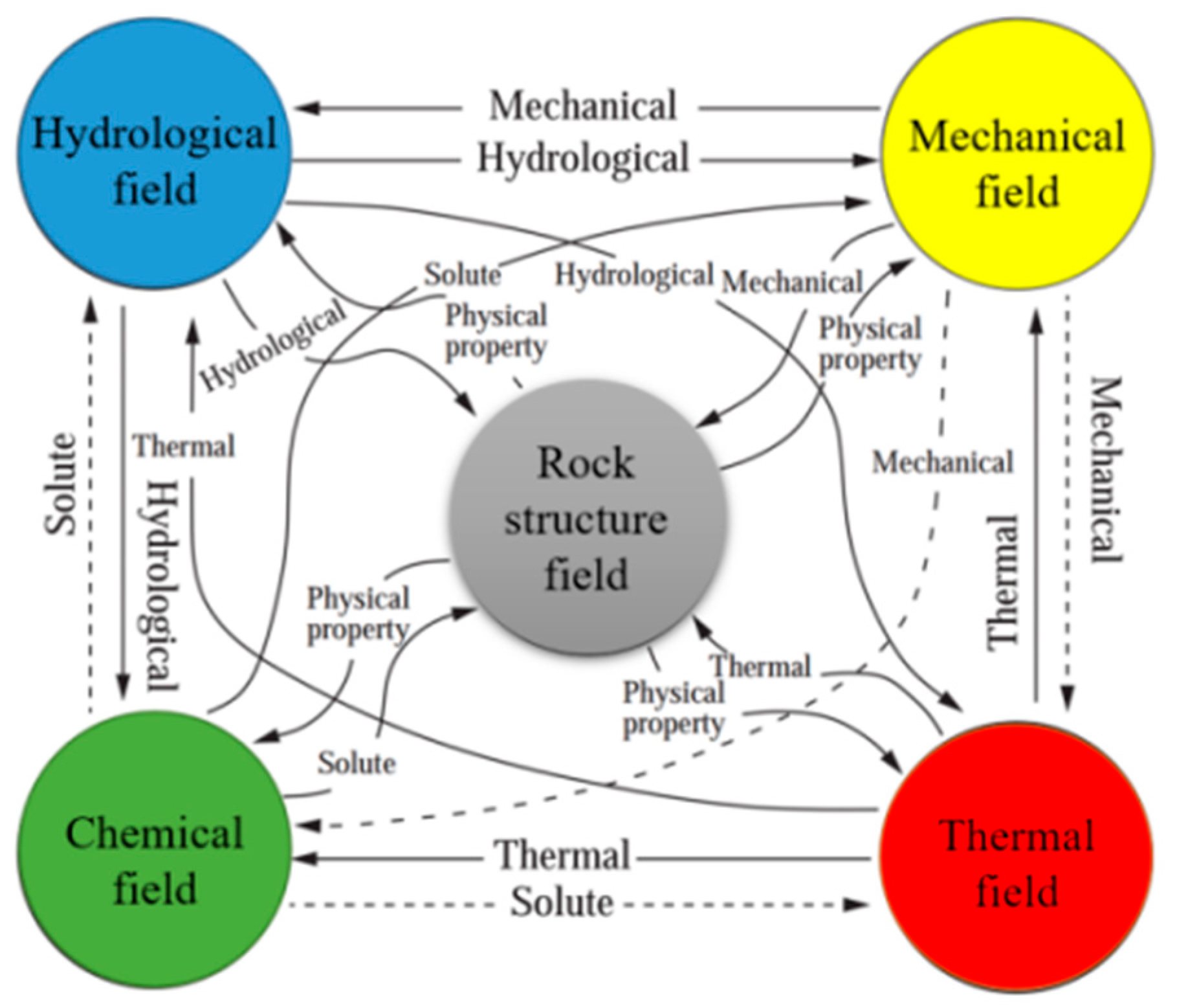
4.2. Multi-Field Coupling and Evolution Law of Mine Goaf

The CO2 storage—geothermal extraction system in the goaf involves multi-field coupling and evolution law. The multi-field coupling contains mining stress field, the fracture field generated by rock fracture, the hydrological field of mine water, liquid CO2 and gaseous CO2 flow in fractured rocks, the thermal field of goaf heat reservoir, and the mine water-rock-CO2 chemical field, as shown in Figure 11.
The mechanical field in the goaf controls the pore distribution of fractured rocks, which directly affects the seepage path of fluid. The distribution of fluid streamline controls the evolution of thermal field in the goaf, and the thermal strain of rock mass caused by thermal field change affects the evolution of the mechanical field. On the contrary, fluid seepage causes extra stress on the rock mass and affects the evolution of the mechanical field; the internal heat dissipation caused by the rock mass strain affects the thermal field; the change in the thermal field affects the viscosity coefficient of fluid and the mechanical properties of rock mass. The chemical field is affected by the other three fields at the same time. The reaction speed is affected by the temperature field and mechanical field, and the reaction activity is affected by the fluid seepage. On the contrary, chemical reaction changes the density, solute and seepage path of fluid, and changes the mineral composition and strength of rock mass. The endothermic and exothermic processes of chemical reactions influence the thermal field to some extent.
According to the above multi-field evolution law, mine water extraction under a constant pressure will cause changes in the hydrological field and stress field in the goaf and influence CO2 migration. Appropriate extraction pressure can promote CO2 seepage in the goaf; too small extraction pressure will cause huge CO2 loss; too large extraction pressure will reduce the extraction life of the geothermal system. Injection of HP CO2 can change the stress field in the goaf. Excessive injection pressure and flow will lead to instability of the coal pillar dam in the goaf and fracture in the overlying RS. As a result, a large amount of CO2 will leak in the mine or to the surface, which will cause great harm. Therefore, a study should be made on the multi-field evolution law in the goaf on the theoretical basis of multi-field coupling and its evolution law in the goaf, and by means of experiment and numerical simulation. Moreover, reasonable geothermal water extraction pressure, holes layout, CO2 injection pressure and injection flow should be put forward in combination with engineering practice. These will help us coordinate mine geothermal extraction and CO2 storage and avoid mutual interference between the two. By this, we can make full use of the underground space and geothermal resources in the goaf, extend the lifetime of geothermal extraction in the goaf, reduce the impact of geothermal water extraction on the surface, and avoid huge CO2 seepage into the atmosphere.

5. Techniques for Geothermal Extraction and CO2 Storage

The key techniques for geothermal extraction and CO2 storage are shown in Figure 12.

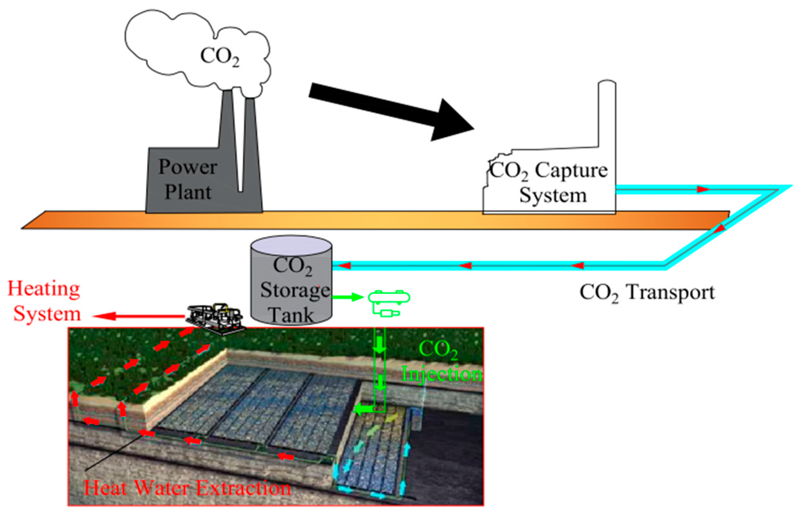
5.1. CO2 Capture and High-Concentration CO2 Transport in Power Plants

CO2 is generated by power generation in coal power plants. In order to obtain high-purity CO2, reduce energy consumption, and increase net carbon sequestration, it is necessary to adopt efficient, cheap and low-carbon CO2 capture and transportation methods.
CO2 capture technologies in coal power plants include pre-combustion capture, in-combustion capture, and post-combustion capture. Pre-combustion capture utilizes coal gasification and reforming technologies to separate CO2 from coal. The process is complex and the CO2 capture cost is high, but a high concentration of CO2 can be produced through the separation. In-combustion capture mainly uses the oxygen-enriched combustion technology, in which the concentration of the captured CO2 is as high as 95%. However, the power consumption of oxygen production equipment is too high and will reduce the net carbon sink. Post-combustion capture technology is relatively mature. It uses alkaline absorbents to absorb CO2 and releases it for CO2 capture. This method is cheap, but the concentration of captured CO2 is low. CO2 transportation refers to transporting the separated CO2 to the storage site through pipelines or by transportation means. Due to the differences in the distance and means of transportation, carbon emissions and costs during transportation are different, which will influence the final net carbon sequestration.
Based on the costs and carbon emissions in CO2 capture and transportation, multi-index evaluation methods, covering cost, carbon emissions, safety, etc., have been set up. According to the distance between the power plant and the adjacent mine, a variety of CO2 capture and transportation portfolios have been established. These portfolios will be evaluated comprehensively with the multi-index evaluation method. With these methods, we can select the greenest, most economical, and safest CO2 transportation method, increase the net amount of CO2 storage, and reduce the storage cost.

5.2. Boreholes, HP Pipelines and Pipeline Supports in the Goaf

Whether injecting supercritical CO2 into the goaf or extracting geothermal water from the goaf, the boreholes, pipeline layout and pipeline supports cannot be ignored. Drilling holes and arranging supports in the goal is a technical problem, due to the accumulation of fractured rocks, the complex structure and stress distribution of fractured rocks, sediment blockage and pipeline shearing in the pipelines arranged in the goaf.
To solve the problems of supporting the boreholes and the blockage of pipeline layout in the goaf, large diameter rigid casings are used to support the transportation and extraction pipelines (Figure 13). The boreholes are connected to the “annular” large pore area on the goaf floor, which promotes the seepage of injected CO2 in the fractured rocks, and enables CO2 to fully migrate to the open space around the mine.
In the hole-forming, pipe-jacking, and hole-sealing technology, a high-power drilling rig is used. After the coal pillar dam is drilled to the designated position, the drilling is withdrawn. The drill bit is removed, and the high-strength protective pipe is pushed into the borehole using the thrust of the drilling rig. The protective pipe head is installed with a screen tube and is sealed. After installation, the gaps around the protective pipe are filled with polyurethane, then the HP CO2 injection hose is installed into the protective pipe. The gap between the hose and the protective pipe is filled with grout to seal the pipe. Finally, the hose is connected to the HP CO2 transportation pipeline.

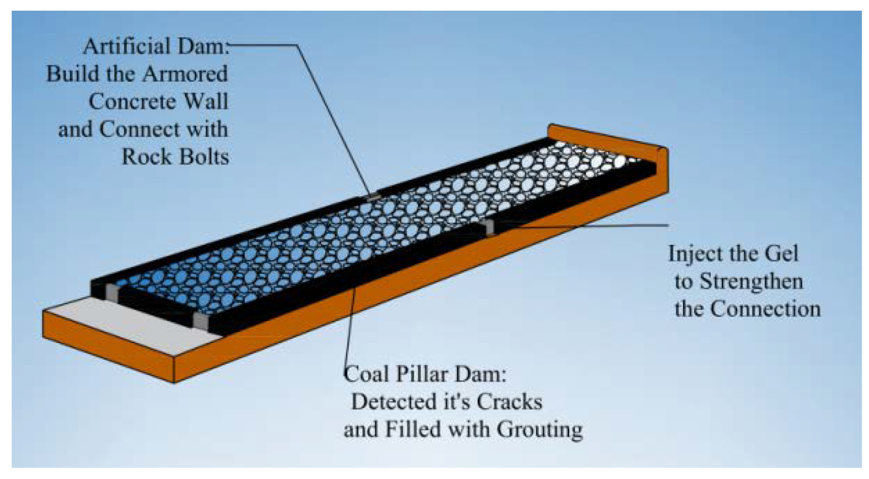
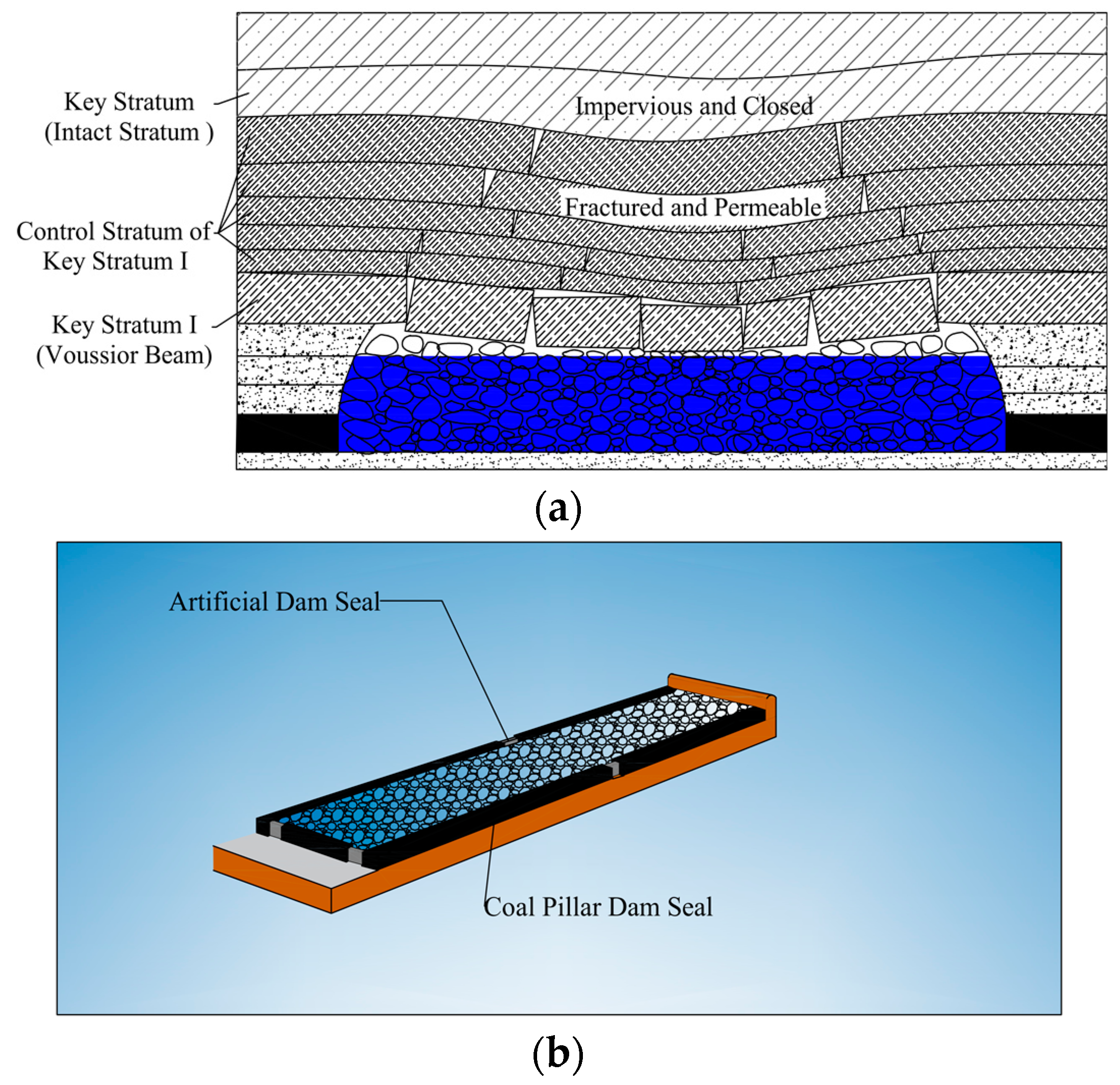
5.3. Sealing and Pressurizing Technology in the Goaf

When the goaf is used for CO2 storage, it is necessary to prevent the gaseous or liquid CO2 injected into the goaf from leaking into the coal mine through the fissures of the goaf coal pillar, artificial dam, sealing wall, return airway, etc. A large amount of underground CO2 leakage will cause serious accidents. Therefore, before injecting CO2, it is necessary to evaluate and deal with the tightness of the goaf, as shown in Figure 14.
A certain amount of natural tracer gas can be injected into the goaf, and a detection point and corresponding equipment can be set up at intervals around the goaf. If the leakage of tracer gas is detected at a certain measuring point, it means that there are leakage fissures in this section of surrounding rock or coal wall, which needs to be sealed. Sealing treatment can be conducted by grouting the surrounding rock or coal wall. The goaf can be filled with concrete-based colloid to seal the wall fissures and the roof-floor joints. Otherwise, gel can be injected into the coal mass, then condense and solidify inside the coal mass, which will prevent air leakage.
Since the liquid pressure is omnidirectional, the goaf should be able to withstand large lateral loads. The abilities of coal pillars and artificial dams to withstand lateral compression in the goaf are evaluated, using professional simulation software such as FLAC3D, UDEC, and ANSYS. The overlying RS pressure and CO2 storage pressure are taken as boundary conditions, and the weakening to the strength of the coal pillar dam caused by fluid seepage should be considered [50,51,52,53]. If the strength of the coal pillar or artificial dam in the goaf is insufficient, artificial reinforced concrete dams can be built outside the coal pillar dam and the artificial dam. Bolts can be used to connect them, so that the overall coal pillar is stressed. Thus, the aspect ratio of the coal pillar is artificially changed, thereby improving the ability of the dam body to withstand lateral loads.

5.4. Underground CO2 Leakage and CO2 Migration Monitoring Technology in the Goaf

The migration law of CO2 injected into the goaf was explored to understand CO2 migration and storage in the goaf, fractured overlying RS, and overlying aquifer, and to evaluate the safety and effectiveness of using the goaf for CO2 storage. By monitoring the PH value of the surface soil, the influence of CO2 leakage on the environment was studied to discover various potential dangers. By monitoring the CO2 concentration in the underground pipelines and the air around the goaf, the safety of transportation pipelines was monitored in real time, to evaluate the tightness of the goaf, and to prevent accidents caused by huge CO2 leakage in the mine.
Because sampling and measurement are simple and rapid, at a low price and analysis cost, the natural tracer sulfur hexafluoride (SF6) can be used to study the migration law of CO2 in the goaf. SF6 was mixed with CO2 in a certain proportion, and the mixed gas was injected into the goaf. Then, gas patterns were obtained from inside the goaf, the overlying RS of the goaf, and the overlying aquifer of the goaf by drilling holes in the ground. Then, a gas chromatograph was used to detect the tracer content. According to the contents of the tracers in different locations, the CO2 migration law can be verified, the principle of CO2 storage in the goaf can be analyzed, and the capacity of CO2 storage in the goaf can be evaluated.
Soil samples near the goaf were collected on the surface, their PH values and conductivities were measured, and CO2 concentration was analyzed. If the measured CO2 concentration on the surface is too high, it means that there are fissures in the goaf directly leading to the surface, so that a large amount of CO2 injected into the goaf leaks to the surface. Therefore, grouting and sealing measures must be conducted on the surface and the overlying RS in the goaf to reduce CO2 leakage into the atmosphere.

5.5. High-Efficiency Variable-Condition Heat Pump and Gas-Liquid Separation Technology

COP (energy efficiency ratio), an important parameter of water source heat pump, is influenced by the unit structure, water source quality, cooling medium, and the heat exchanger structure. Because there are great differences in the temperature and quality of the extracted mine water, shallow groundwater, domestic water, etc., the energy efficiency ratio of the heat pump unit should be improved to produce more heat energy with less power consumption. Thus, the components of the heat pump unit should be designed and optimized according to the practical working conditions such as the temperature, quality, and flow rate of the extracted mine water, so as to realize high-efficiency operation of the heat hump with low energy consumption. The fluid obtained by the heat pump is introduced into the underground system from the shaft, and recharged into the fractured rocks in the goaf, making full use of the mine water geothermal resources.
When geothermal water is extracted from underground mines, it takes some CO2 with it. In order to prevent the extracted gaseous CO2 from impacting the surface heat pump unit, it is necessary to separate the CO2 from the extracted mine water underground. At present, domestic and overseas gas-liquid separation technologies include gravity gas-liquid separation, inertial gas-liquid separation, centrifugal gas-liquid separation, rectification gas-liquid separation, etc. An overall evaluation is conducted, according to the ratio of gaseous CO2 in the extracted hot water and the extraction parameters, and based on the power consumption, carbon emission, safety, cost and other indicators of the process and equipment. The most suitable gas-liquid separation technology and equipment are applied in this process.

6. Discussions

6.1. Limitations

At present, this technology lacks the utilization of the CO2 resource, and it takes a long time (50–100 years) to convert CO2 into carbonate ores. CS in deep mine goaf will lead to a higher pore pressure and make surrounding rock undergo higher lateral pressure than the original water storage pressure. This will require high-strength materials to seal the goaf and may lead to mine rock burst.

6.2. Further Studies

Firstly, a specific economic evaluation of the technology is required, including the cost and income of operating the system at different flow rates and depths, under different pressures of the mine, geological conditions, and climatic conditions, and in different seasons. Methods of constructing the system at a lower cost are discussed and studied, such as filling and sealing the goaf with waste gangue and colloid, and constructing the in-situ geothermal utilization system. Secondly, the feasibility of the technology can be further demonstrated, involving the influence of CO2 migration and accumulation on the overlying RS of the goaf, the possible leaking path of CS in the goaf, and the blocking method. If possible, field tests should be executed in the goaf of an abandoned mine to explore new methods and approaches of CS technology in the goaf under actual conditions.

7. Conclusions

(1) The CO2 storage and geothermal extraction technology of high temperature and HM water in deep mine is firstly proposed, integrating the geothermal extraction technology in the high temperature mine and the CO2 storage technology in the goaf. It aims at using the underground space in the goaf to store CO2, while softening HM mine water, and extracting geothermal resources from the high-temperature mine water.
(2) The feasibility of CO2 storage in the goaf is proved theoretically, and the technical principle of synergic operation of CO2 storage and geothermal extraction is explained. While CO2 is stored in the goaf, the corrosion of geothermal water on the extraction equipment is greatly alleviated. The extracted mine water forms a depressed-down funnel, which promotes full CO2 seepage in the fractured rocks in the goaf.
(3) The general scheme of synergistic technology of CO2 storage and geothermal extraction in the deep mine at a high temperature and the HM water is proposed, which includes CO2 capture and transportation, the sealing of the goaf, the injection of HP CO2, and the extraction of hot water in the goaf. It puts forward the scientific issues of synergistic technology of CO2 storage—geothermal extraction in the goaf, including the evolution law of CO2 migration—storage in the goaf.
(4) Five key techniques of CO2 storage and geothermal extraction of high temperature and HM water in deep mine are proposed: high concentration CO2 capture and transportation, goaf pressurization and sealing, goaf drilling and support, detection of CO2 migration, and high-efficiency heat pump.

Author Contributions

Conceptualization, J.Y. and F.W.; methodology, F.W.; software, F.W. and J.Y.; validation, F.W. and J.Y.; formal analysis, F.W.; investigation, F.W.; resources, F.W.; data curation, F.W.; writing—original draft preparation, F.W. and J.Y.; writing—review and editing, J.Y.; visualization, F.W. and J.Y.; supervision, F.W. and J.Y.; project administration, F.W.; funding acquisition, F.W. All authors have read and agreed to the published version of the manuscript.

Funding

Financial support for this work was provided by the National Natural Science Foundation of China (51974297).

Institutional Review Board Statement

Not applicable.

Informed Consent Statement

Not applicable.

Data Availability Statement

Data are contained within the article.

Conflicts of Interest

The authors declare no conflict of interest.

Abbreviations

TermAbbreviation
Highly mineralizedHM
High temperatureHT
High pressureHP
Water-rock-CO2 effectWRCE
Geothermal extraction and utilizationGEU
Rock strataRS
CO2 storageCS
Underground coal gasificationUCG
Carbon capture and storageCCS

References

  1. Xie, H.P.; Ren, S.H.; Xie, Y.C.; Jiao, X.M. Development opportunities for coal industry under carbon neutrality target. J. China Coal Soc. 2021, 46, 2197–2211. [Google Scholar]
  2. Jin, Y.N.; Zheng, N.; Tian, Z.; Li, T.Y. Challenges and opportunities for the oil and gas industry from the Carbon Neutral Vision. Techno-Econ. Petrochem. 2021, 37, 1–6. [Google Scholar]
  3. Zhang, Y.S.; Chao, Q.C.; Chen, Y.; Zhang, J.Y.; Wang, M.; Zhang, Y.; Yu, X. China is carbon neutral: Leading global climate governance and green transformation. Int. Econ. Rev. 2021, 9, 2150019. [Google Scholar]
  4. Yang, Y.; Yu, H.Y.; Lu, G.; Wang, L.M.; Zhao, Y.; Hao, L.S.; Ren, D.M.; Fang, W.; An, H.Z.; Cai, T.G. Interview on the unprecedented changes of energy geopolitics and national energy security. J. Nat. Resour. 2020, 35, 2803–2820. [Google Scholar] [CrossRef]
  5. Chen, F.; Wang, S.Y.; Yu, H.C.; Chen, R.; Yang, Y.J.; Lu, J.S. The technological path of coal revolution under carbon neutral target. J. China Coal Soc. 2022, 47, 1452–1461. [Google Scholar]
  6. He, X.Q.; Tian, X.H.; Song, D.Z. Research progress and prospect of CO2 safe storage in coal seam. Coal Sci. Technol. 2022, 50, 212–219. [Google Scholar]
  7. Aminu, M.D.; Nabavi, S.A.; Rochelle, C.A.; Manovic, V. A review of developments in carbon dioxide storage. Appl. Energy 2017, 208, 1389–1419. [Google Scholar] [CrossRef]
  8. Liu, Y.H.; Ge, Q.S.; He, F.N.; Cheng, B.B. Countermeasures against international pressure of reducing CO2 emissions and analysis on China’s potential of CO2 emission reduction. Acta Geogr. Sin. 2008, 63, 675–682. [Google Scholar]
  9. Cao, C.; Hou, Z.M.; Xiong, Y.; Luo, S.J.; Fang, Y.Q.; Sun, W.; Liao, J.X. Technical routes and action plan for carbon neutral for Yunnan Province. Adv. Eng. Sci. 2022, 54, 37–46. [Google Scholar]
  10. Zou, C.N.; He, D.B.; Jia, C.Y.; Xiong, B.; Zhao, Q.; Pan, S.Q. Connotation and pathway of world energy transition and its significance for carbon neutral. Acta Pet. Sin. 2021, 42, 233–247. [Google Scholar]
  11. Javier, M.; Almudena, O.; Fernández-Oro, J.M.; Loredo, J.; Díaz-Aguado, M.B. Feasibility analysis of using mine water from abandoned coal mines in Spain for heating and cooling of buildings. Renew. Energy 2020, 146, 1166–1176. [Google Scholar]
  12. Sun, Y.J.; Chen, G.; Xu, Z.M.; Yuan, H.Q.; Zhang, Y.Z. Research progress of water environment, treatment and utilization in coal mining areas of China. J. China Coal Soc. 2020, 45, 304–316. [Google Scholar]
  13. Sun, Y.J.; Xun, Z.M. Mine water drainage pollution in China’s coal mining areas and the construction of prevention and control technical system. Coal Geol. Explor. 2021, 49, 1–16. [Google Scholar]
  14. Sun, Y.J.; Zhang, L.; Xu, Z.M.; Chen, G.; Zhao, X.M.; Li, X.; Gao, Y.T.; Zhang, S.G.; Zhu, L.L. Multi-field action mechanism and research progress of coal mine water quality formation and evolution. J. China Coal Soc. 2022, 47, 423–437. [Google Scholar]
  15. Shan, Y. Water-Rock Interaction of Coal-Bearing Strata and Environmental Effect of Mine Water; China University of Mining and Technology: Beijing, China, 2009. [Google Scholar]
  16. Zhang, Y.Z. Chemical Characteristics and Genetic Mechanism of Mine Water in Xin Julong Coal Mine; China University of Mining and Technology: Beijing, China, 2021. [Google Scholar]
  17. Li, X.; Sun, Y.J.; Chen, G.; Wang, H.Z.; Zhang, Z.J. Medium conditons and influence mechanism of high salinity mine water transfer and storage by deep well recharge. Coal Geol. Explor. 2021, 49, 17–28. [Google Scholar]
  18. Xu, Z.M.; Noble Sun, Y.J.; Cui, S.Y.; Zhang, M.F.; Chen, Z.S.; Wu, J.F. A study of conditions of water bearing media and water dynamics in typical Jurassic coal rich regions in western China. J. China Coal Soc. 2017, 42, 444–451. [Google Scholar]
  19. Xie, H.P.; Gao, F.; Ju, Y. Quantitative definition and investigation of deep mining. J. China Coal Soc. 2015, 40, 1–10. [Google Scholar]
  20. Yuan, L. Heoretical analysis and practical application of coal mine cooling in Huainan mining goaf. J. Min. Saf. Eng. 2007, 24, 298–301. [Google Scholar]
  21. Du, J.P. Mining Engineering; China University of Mining and Technology Press: Beijing, China, 2013. [Google Scholar]
  22. Wang, S.M.; Shen, Y.J.; Sun, Q.; Liu, L.; Shi, Q.M.; Zhu, M.B.; Zhang, B.; Cui, S.D. Underground CO2 storage and technical problems in coal mining area under the “dual carbon” target. J. China Coal Soc. 2022, 47, 45–60. [Google Scholar]
  23. Liu, L.; Wang, S.M.; Zhu, M.B.; Zhang, B.; Hou, S.D. CO2 storage-cavern construction and storage method based on functional backfill. J. China Coal Soc. 2022, 47, 1072–1086. [Google Scholar]
  24. Roddy, D.J.; Younger, P.L. Underground coal gasification with CCS: A pathway to decarbonising industry. Energy Environ. Sci. 2010, 3, 400–407. [Google Scholar] [CrossRef]
  25. Zhang, K.; Gao, Q.; Jiang, B.B.; Han, J.M.; Chen, M.Y. Experimental study on the mechanism of water-rock interaction in the coal mine underground reservoir. J. China Coal Soc. 2019, 44, 3760–3772. [Google Scholar]
  26. Han, J.M.; Gao, J.; Du, K.; Chen, M.Y.; Jiang, B.B.; Zhang, K. Analysis of hydrochemical characteristics and formation mechanism in coal mine underground reservoir. Coal Sci. Technol. 2020, 48, 223–231. [Google Scholar]
  27. Wu, B.Y.; Li, Q.S.; Cao, Z.G.; Guo, Q.; Kong, J.F.; Wu, S.Q.; Zhang, Z.X. Influence of high salt mine water storaged in underground reservoir of coal mine on Groundwater. J. China Coal Soc. 2021, 46, 2360–2369. [Google Scholar]
  28. Zhi, G.J.; Ju, J.F.; Liu, R.; Yang, R.G.; Fang, Z.Y.; Zhang, C.P. Water-rock interaction and its influence on water quality in the underground reservoir. J. Min. Saf. Eng. 2022, 39, 779–785. [Google Scholar]
  29. Jin, Y.Q. Study on Genesis Mechanism of Soft Rock Controlled Landslide in Coal Measure Strata in Shanxi Province; Taiyuan University of Technology: Taiyuan, China, 2021. [Google Scholar]
  30. Zheng, Q.M.; Liu, Q.F.; Wu, Z.G.; Zhang, Y.M.; Shi, S.L. Ammonium-illite smectite interlayer clay minerals in coal-bearing strata in Jincheng district of Shanxi Province. J. China Coal Soc. 2012, 37, 231–236. [Google Scholar]
  31. Li, X.L.; Sun, Z.X.; Liu, J.H. Hydrogeochemistry; Atomic Energy Edition: Beijing, China, 1982. [Google Scholar]
  32. Fang, Z.Y. Research on Mechanism of Purifying Underground Reservoir Water Storage by Collapse Coal Rock in Goaf of Wanli No.1 Mine; China University of Mining and Technology: Beijing, China, 2020. [Google Scholar]
  33. Wang, P.; Zhou, L.; Xu, X.; Shi, B.W.; Feng, Q.Y. Experimental simulation of residual CO2-mine water-rock interaction in gas closure mine. Saf. Coal Mines 2020, 51, 38–44. [Google Scholar]
  34. Ryzhenko, B.N. Genesis of dawsonite mineralization: Thermodynamic analysis and alternatives. Geochem. Int. 2006, 44, 835–840. [Google Scholar] [CrossRef]
  35. Qu, X.Y.; Liu, L.; Gao, Y.Q.; Liu, N.; Peng, X.L. Study on the characteristics and stability of lamellar allite in sandstone. Geol. Rev. 2008, 837–844+869. [Google Scholar] [CrossRef]
  36. Zhou, X.H.; Men, J.L.; Song, D.P.; Li, C.Y. Study on optimum drilling parameters of coal seam anti-reflection by liquid CO2 blasting. Chin. J. Rock Mech. Eng. 2016, 35, 524–529. [Google Scholar]
  37. Wan, Y.Y. Characteristics of CO2 Migration and Transformation in CO2 Geological Storage in Saltwater of Shiqianfeng Formation, Ordos Basin; Jilin University: Changchun, China, 2012. [Google Scholar]
  38. David, B.; Athresh, A.; Al-Habaibeh, A.; Burnside, N.M. Water from abandoned mines as a heat source: Practical experiences of open- and closed-loop strategies, United Kingdom. Sustain. Water Resour. Manag. 2019, 5, 29–50. [Google Scholar]
  39. He, M.C.; Xu, M. Research and development of HEMS deep well cooling system and countermeasures of heat damage control. Chin. J. Rock Mech. Eng. 2008, 27, 1353–1361. [Google Scholar]
  40. Wan, Z.J.; Bi, S.K.; Zhang, Y.; Wang, J.H.; Wu, D.; Wang, Y.C. Theoretical and technical framework of coal-thermal co-mining. J. China Coal Soc. 2018, 43, 2099–2106. [Google Scholar]
  41. Zhang, B.; Xue, P.Y.; Liu, L.; Huan, C.; Wang, W.; Zhao, Y.D.; Qin, X.B.; Yang, Q.X. Exploration of ore-geothermal cooperative mining method in deep filling mine. J. China Coal Soc. 2021, 46, 2824–2837. [Google Scholar]
  42. Pu, H.; Bian, Z.F.; Zhang, J.X.; Xu, J.C. Research on a waste mine geothermal resource recycling system. J. China Coal Soc. 2021, 46, 677–687. [Google Scholar]
  43. Rudakov, D.; Inkin, O. Evaluation of heat supply with maintaining a safe mine water level during operation of open geothermal systems in post-coalmining areas. Min. Miner. Depos. 2022, 16, 24–31. [Google Scholar] [CrossRef]
  44. Randlopn, J.B.; Saar, M.O. Combining geothermal energy capture with geologic carbon dioxide sequestration. Geophys. Res. Lett. 2011, 38, L10401. [Google Scholar]
  45. Georges, B.; Ali, N.; Assima, G.P.; Lechat, K.; Gras, A.; Entezari, A.; Kandji, E.H.B.; Awoh, A.-S.; Horswill, M.; Turcotte, S.; et al. Passive Mineral Carbonation of Mg-rich Mine Wastes by Atmospheric CO2. Energy Procedia 2017, 114, 6083–6086. [Google Scholar]
  46. Li, H.Y.; Peng, S.M.; Xu, M.Y.; Luo, C.; Gao, Y. Research progress on CO2 storage mechanism in deep salt water layer. Sci. Technol. Rev. 2013, 31, 72–79. [Google Scholar]
  47. Bacci, G.; Korre, A.; Durucan, S. Experimental investigation into salt precipitation during CO2 injection in saline aquifers. Energy Procedia 2011, 4, 4450–4456. [Google Scholar] [CrossRef]
  48. Ketzer, J.M.; Iglesias, R.; Einloft, S.; Dullius, J.; Ligabue, R.; Lima, V.D. Water–rock–CO2 interactions in saline aquifers aimed for carbon dioxide storage: Experimental and numerical modeling studies of the Rio Bonito Formation (Permian), Southern Brazil. Appl. Geochem. 2009, 24, 760–767. [Google Scholar] [CrossRef]
  49. Yan, B.Q.; Ren, F.H.; Cai, M.F.I.; Guo, Q.F.; Qiao, C. A review on physical and mechanical properties and constitutive models of rock under multi-field coupling of THMC. Chin. J. Eng. 2020, 42, 1389–1399. [Google Scholar]
  50. Wang, F.T.; Liang, N.N.; Li, G. Damage and failure evolution mechanism for coal pillar dams affected by water immersion in underground reservoirs. Geofluids 2019, 2019, 2985691. [Google Scholar] [CrossRef]
  51. Zhang, C.; Han, P.H.; Wang, F.T.; He, X. Stability of residual coal pillar in underground reservoir under mining water leaching. J. China Univ. Min. Technol. 2021, 50, 220–227+247. [Google Scholar]
  52. Zhang, C.; Wang, F.T.; Bai, Q.S. Underground space utilization of coalmines in China: A review of underground water reservoir construction. Tunn. Undergr. Space Technol. 2021, 107, 103657. [Google Scholar] [CrossRef]
  53. Wang, F.T.; Liang, N.N.; Li, G.; Zhao, B. Damage and failure law of coal pillar dam under complex stress environment. J. Min. Saf. Eng. 2019, 36, 1145–1152. [Google Scholar]
Figure 1. Greenhouse gas control.
Sustainability 14 12322 g001
Figure 2. CO2 storage—geothermal extraction system in deep mine.
Sustainability 14 12322 g002
Figure 3. SEM micrographs of kaolinite before and after reaction [33]: (a)—before reaction; (b)—after reaction.
Sustainability 14 12322 g003
Figure 4. SEM micrographs of calcite before and after reaction [33]: (a)—before reaction; (b)—after reaction.
Sustainability 14 12322 g004
Figure 5. CO2 RS storage in the goaf: (a)—vertical seal; (b)—crosswide seal.
Sustainability 14 12322 g005
Figure 6. Thermal cascade process system in deep mine A goaf geothermal extraction model (Figure 7) was established. The effect of geothermal extraction in the goaf was simulated at a ground temperature of 60 °C, 0.03 °C/100 m, under the extraction pressure of 0.03 MPa, at a recharge flow rate of 0.06 m3/s, and at a recharge temperature of 283 K. The temperature change in the goaf is shown in Figure 8. The extraction temperature can reach above 330 K within the range of 0–10a, and the temperature difference between the inlet and outlet of the fluid reaches about 47 K (Figure 9). Taking the average temperature of 325 K (52 °C) in the first 20a of this simulation as the extraction temperature, the heat loss along the way to the ground is about 9–10 °C, then the water inlet temperature on the evaporation side of the ground heat pump is about 42 °C. Taking the heating design heat index as 60 W/m2, the extraction system can sustainably supply heat within a coverage of 180,837 m2 in winter, and reduce greenhouse gas emissions by about 6690 tons each year.
Sustainability 14 12322 g006
Figure 7. Goaf GEU model.
Sustainability 14 12322 g007
Figure 8. Change in temperature in the goaf during extraction.
Sustainability 14 12322 g008
Figure 9. Effect of the goaf GEU system.
Sustainability 14 12322 g009
Figure 10. CO2 migration-storage evolution in the mine goaf.
Sustainability 14 12322 g010
Figure 11. Multi-field coupling in the goaf [49].
Sustainability 14 12322 g011
Figure 12. Basic framework of CS-GEU system in deep mine goaf.
Sustainability 14 12322 g012
Figure 13. Boreholes in the goaf.
Sustainability 14 12322 g013
Figure 14. Mine goaf reinforcement.
Sustainability 14 12322 g014
Table 1. Energy spectrum analysis of mineral elements after water–rock interaction [32].
MineralElementAtomic Fraction before Reaction
/%
Atomic Fraction after Reaction
/%
Chlorite in coalMg0.950.89
Al9.889.2
Si14.1510.84
Kaolinite in coalAl15.8712.63
Si17.5413.56
Illite in coalAl11.874.56
Si17.1913.96
Kaolinite in sandy mudstoneAl14.049.04
Si15.719.95
Chlorite in sandy mudstoneMg5.911.18
Calcite in sandstoneCa17.315.51
Table 2. Analysis of elemental changes before and after kaolinite reaction under the effect of CO2 [33].
Chemical ElementProportion of Main Elements/%
Before ReactionAfter Reaction
CO2
C08.53
Si22.0917.90
Al27.4322.84
O48.7650.49
Table 3. Analysis of elemental changes before and after calcite reaction under the effect of CO2 [33].
Chemical ElementProportion of Main Elements/%
Before ReactionAfter Reaction
CO2
C11.211.35
O42.4642.1
Ca46.3546.56
Publisher’s Note: MDPI stays neutral with regard to jurisdictional claims in published maps and institutional affiliations.

