Article

Integrated PV–BESS-Fed High Gain Converter for an LED Lighting System in a Commercial Building

by
Augusti Lindiya Susaikani
1,
Subashini Nallusamy
1,
Uma Dharmalingam
1,
Yonis M. Buswig
2,*,
Natarajan Prabaharan
1,* and
Mohamed Salem
3
1
Department of EEE, SASTRA Deemed to Be University, Thanjavur 613401, Tamil Nadu, India
2
Institute of Sustainable and Renewable Energy ISuRE, Faculty of Engineering, University Malaysia Sarawak, Kota Samarahan 94300, Sarawak, Malaysia
3
School of Electrical and Electronic Engineering, Universiti Sains Malaysia (USM), Nibong Tebal 14300, Penang, Malaysia
*
Authors to whom correspondence should be addressed.
Sustainability 2022, 14(19), 12296; https://doi.org/10.3390/su141912296
Submission received: 24 June 2022 / Revised: 5 August 2022 / Accepted: 26 August 2022 / Published: 27 September 2022
(This article belongs to the Section Energy Sustainability)

Abstract

:
The demand for electricity is rapidly growing and renewable energy sources such as solar, wind and tidal energy can compensate the demand to a substantial level. Among these, solar energy is abundant, scalable and is cheaper. The generated energy can be used in an efficient way if the DC output is directly supplied to the load instead of converting it to AC. Every electrical system is capable of operating in DC and, for example, energy efficient Light Emitting Diode (LED) lights have become popular as they provides more lumens with less power consumption and also can be directly operated from DC. LED lighting system in large commercial buildings has irradiance levels which vary sigificantly during operation. Extracting maximum power from the energy system and maintaining constant voltage output at different loads is another challenge. This paper proposes a solar Photo Voltaic (PV)-based energy system including Battery Energy Storage System (BESS) for supplying LED lamps to a commercial building through a modified high gain Luo converter. The Perturb and Observe control algorithm has been used for maximum power extraction from a PV cell whereas PI (Proportional Integral) controllers maintain constant output voltage from PV–BESS against different irradiance levels. To supply the desired voltages to the LED lighting system, a modified high gain Luo converter is designed. To make the output voltage constant at different load currents, PI and Sliding Mode Controllers (SMC) are designed with the help of the state-space average model. It is found that the sliding mode controller outperforms the PI controller in terms of behavior in the transient period and tracking capability. The system is simulated using MATLAB/Simulink®. The Sliding Mode Controller has a 95% less transient period and is 75% faster in tracking capability when compared to other controllers. The system could be incorporated with the PV source to obtain green energy.

1. Introduction

In recent years, due to the depletion of fossil fuels and increased demand of electrical energy, renewable energy sources are widely used for power generation. Additionally, policymakers around the world are emphasizing the ill effects of burning fossil fuels leading to climate change. As a result, the world is moving towards green energy and the energy sector is using both renewable and traditional energy sources to supply the increasing demand [1]. Among the different renewable sources of energy, solar energy has become popular as it is available in abundance in countries such as India with less maintenance, scalability and steady decline in the price of photovoltaic components. This leads to solar power generation being clean, environmentally friendly and having a low cost per unit energy generation. Solar energy, which is greener, cleaner and sustainable and distributed through a cost-effective simple system for sustainable loads, is the focus of this research. Generation of electricity from solar improves the quality of life in rural areas as it supplies energy to health centers and street lighting. There is more probability of creating jobs and therefore, it stimulates sustainable socio-economic growth [2].
The stand-alone mode of generating energy using solar is a simple solution which avoids a connection to a grid and conversion. The main advantage of such stand-alone generation of electric power from Photo Voltaic (PV) is that the DC output from the PV panel after modification, i.e., increasing or decreasing the voltage, can be applied to a DC load [3], which prevents the need for DC to AC conversion and the associated losses. A review article given in [4] presents various aspects of DC micro grid implementation and the relevant architecture suitable for buildings with high renewable energy source production for data centers and electric vehicle charging stations. In [5], a grid-connected, PV-fed Brushless DC motor drive is designed and different Maximum Power Point Tracking (MPPT) algorithms are implemented. Sepic, Luo and Interleaved Luo converters are developed and the system performance is analyzed in terms of converter output voltage, motor parameters and Total Harmonic Distortion in the grid output current. One major application this research focuses on is the DC supply produced by this stand-alone unit to supply lighting in a commercial building [6], as the tariff of commercial usage is many times that of domestic usage.
The lighting technology used must save energy, cost, life, high resolution, colour rendering, contrast, good performance and provide a green environment [7,8]. Selecting the type of lamp based on the above factors is another challenge. A Light Emitting Diode (LED)-based system is preferred for its sustainability by lasting longer, low maintenance, absence of electronic ballasts, provision for focusing light and recyclable parts. Even though the initial cost of an LED lamp is high, it is preferred due to more lumens with less power consumption. In addition, it can be connected directly to the PV along with a simple charge controller so that the renewable energy utilization is more, thereby reducing the CO2 emission [9].
Many converters have been proposed in the literature and the boost converter is a primeval and a simpler converter [10]. Perturb & Observe (P&O), Incremental Conductance, Current sweep method, One cycle control, Artificial Neural Network etc. are some of the MPPT techniques addressed [11,12,13] for extracting maximum power from the PV panel. There is also a need for the battery to provide the supply when PV does not work. The battery gets charged from the output voltage of the solar PV cell using a bi-directional DC-DC converter when PV power is in excess. An isolated solar PV-fed DC microgrid for residential applications is designed along with the Battery Energy Storage System (BESS) in [14] and the performance of the designed system is analyzed in both charging and discharging modes of battery occurring during different irradiance conditions.
There is a need to step up the voltage with a reliable and efficient power electronic converter as the output of the PV cell is of low voltage DC. The PV–Battery system is connected to the load through a suitable converter which should have high efficiency, gain and power density. Among various power electronic converters available [15] to obtain high gain and high efficiency with lower duty cycle, modified high gain Luo converters can be used because of their simplicity [16].
Various topologies and controllers have been developed in the recent literature to enhance the performance of this high gain converter. Two input boost along with a switched-inductor impedance-network proposed in [17], which yields DC voltage magnitude of a desired level with lower ripple and has high conversion efficiency. In [18], a 120 W LED lighting system energized from a photovoltaic panel through a high gain converter is proposed and the analysis is done at a constant irradiation level. A new hybrid high gain converter with a lesser number of components is proposed in [19] with less stress in devices and more efficiency. The dual boost converter combined with the switched inductor structure [20] is discussed to achieve a high conversion ratio requirement with a reasonable duty cycle and makes it suitable for integrating with photovoltaic cells. Two input converters along with a battery are designed in [21], operating in a continuous conduction mode operation to obtain the higher magnitude DC voltage with a fewer number of components.
In addition, to provide the constant output voltage, properly designed linear or nonlinear controllers are to be added with the system. The superiority of the Hybrid Posicast Controller over Proportional Integral Derivative controller designed for Fundamental Positive Output Super–Lift Luo Converter is highlighted [22], and the performance comparison is done in terms of peak overshoot and settling time obtained during the transient period. A nonlinear controller is preferred as it is more sensitive and makes the system robust to load and line variations.
As a PV-based LED lighting system is cost effective in remote places where grid supply is not available, it will be useful to design an LED lighting system fed from solar energy through a high gain converter along with a Battery Energy Storage System. More-over, the lighting system should also be provided with a DC voltage with fewer ripples and maintained constant for wide load power variations.
The main contributions of this research article are:
  • An isolated PV–BESS is designed to obtain constant DC output voltage for varying solar irradiance
  • A linearized small signal model is developed for a modified high gain Luo converter using the state-space averaging technique
  • The mathematical representation of the control component of a sliding mode controller is formulated using the derived small signal model
  • Superior performance of the Sliding Mode Controller (SMC) over the PI controller is projected with respect to time–domain parameters
This article is organized as follows: Section 2 explains the functional block diagram of the entire system, working principle and mathematical modelling of the modified Luo converter. Section 3 explores the analysis of PV–BESS and implementation of the PI and sliding mode controller along with results. The discussion of the results is given in Section 4, and Section 5 states the conclusions.

2. Materials and Methods

2.1. Block Diagram

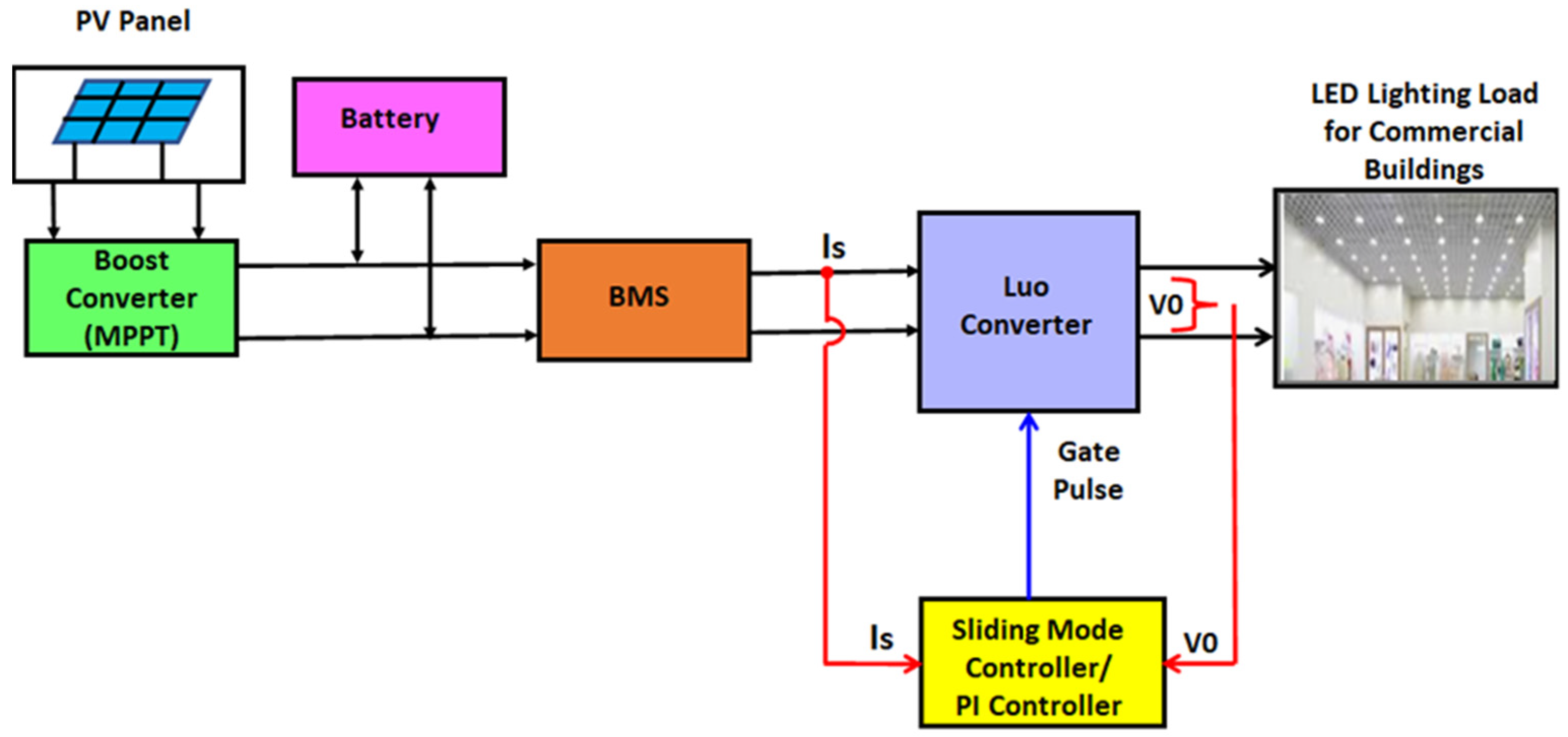
The proposed solar lighting for a commercial building has PV array, a boost converter, a battery with BMS and a modified high gain Luo converter. The system supplies 240 V for approximately 5 parallel strings with each string consisting of 10 LED lamps. Each lamp rating is 24 V, 10 W. The description of each block of the model is discussed below and shown in Figure 1.
The electric supply to the commercial lighting system is obtained from either PV or from Battery. In this work, the built-in solar PV module available in MATLAB 2021/Simulink of model Sovello SV-X-210-yyy is used. To obtain more power even at less irradiance, 4 parallel strings are selected in which each string consists of two series modules. From the solar array characteristics shown in Figure 2, the module ratings are 210 W, cells/module 38, open circuit voltage 23.1 V, short circuit current 12.02 A, voltage at maximum power 18.5 V and current at maximum power 11.36 A.
The P&O algorithm [23] is one of the most efficient and simple as it determines the optimal operating point which gives maximum power with constant open circuit voltage for different irradiance level. To extract maximum power for each irradiance, the P&O algorithm is used and implemented using a boost converter. A boost converter is used to employ an MPPT algorithm such that the power extracted from the PV cell is maximum for each irradiance level. As the PV panel output is dependent on climatic conditions during cloudy periods, the battery plays a significant role for providing continuous supply. The battery employed here is a lithium-ion battery and it can provide a backup for 3 days. The battery of rated capacity 150 Ahr and nominal voltage of 24 V is used here to supply the load when the PV power is not available. It gets charged from the solar array when PV power is more than the required.
The Battery Management System consists of a bi-directional converter and PI controllers designed separately such that the battery gets charged when PV power is greater and discharged when PV power is less. The controllers also help to maintain the input to the high gain converter constant at 48 V. It also ensures safe operation, optimal lifespan and better performance of the battery.
A modified high gain Luo converter is employed to step up the PV–BESS output voltage of 48 V to 240 V and maintained at constant at different loading conditions using a closed loop control system. The PI controller and SMC are designed to make the system stable and robust against load disturbances. In the PI controller, an outer loop voltage controller and inner loop current controllers are designed to generate a control signal. In SMC, the voltage error and source current error are used as state variables and the control signal is developed to maintain the state trajectories in the sliding surface. The Luo converter output is used to supply LED light in a commercial building.

2.2. Modified Luo Converter

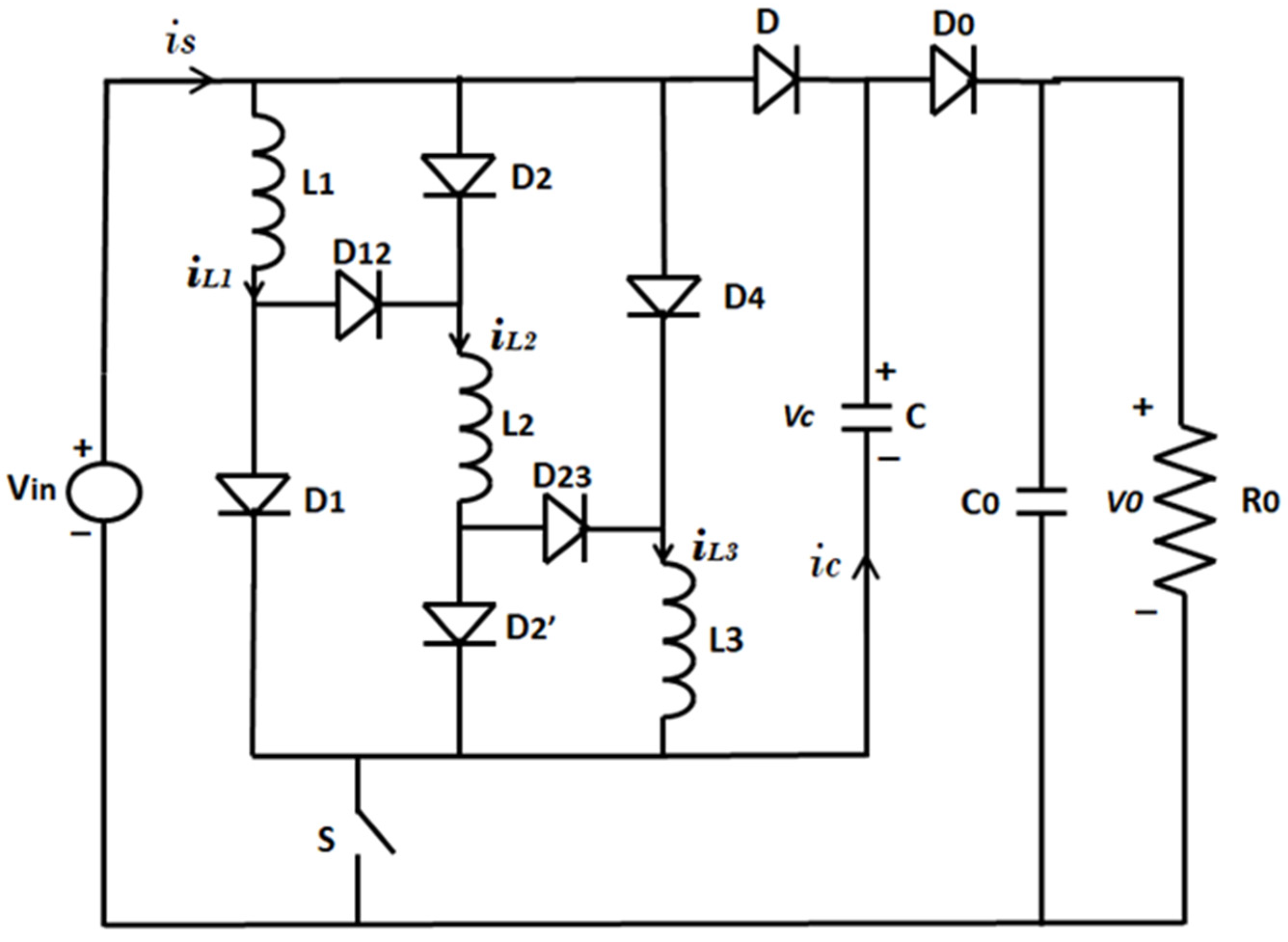
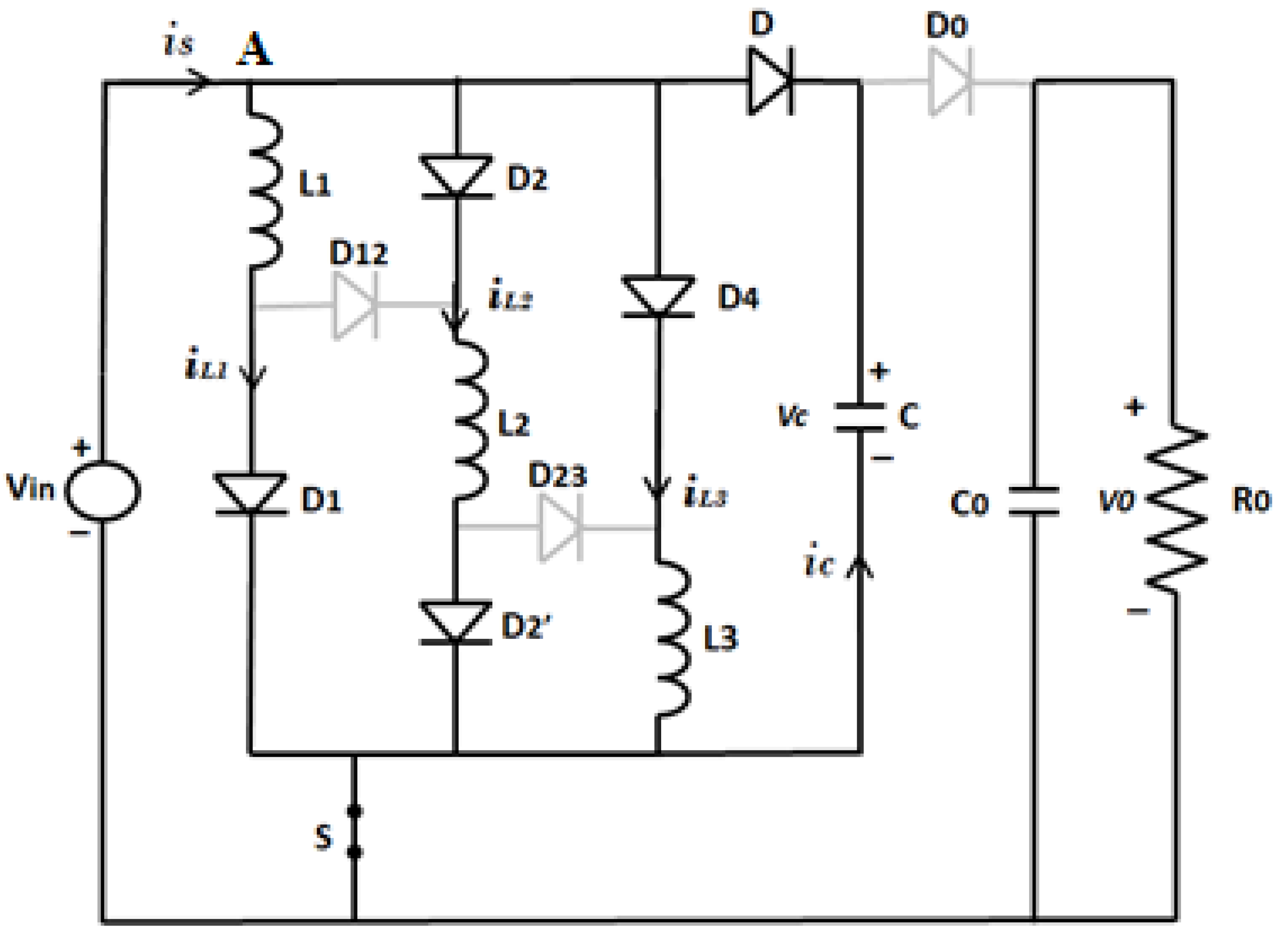
The Luo converter is one of the major components of the proposed system and has a high gain output. This is a kind of boost converter and it has advantages such as larger output range, high power density, less inrush current, high efficiency and nearly zero ripple output. Apart from this, it has less transient and conduction losses as it uses only a single switch. In this work, a modified Luo converter [24] is employed as it provides a better voltage gain than a conventional one. The schematic of the converter is shown in Figure 3. The working of the converter is explained in two modes.
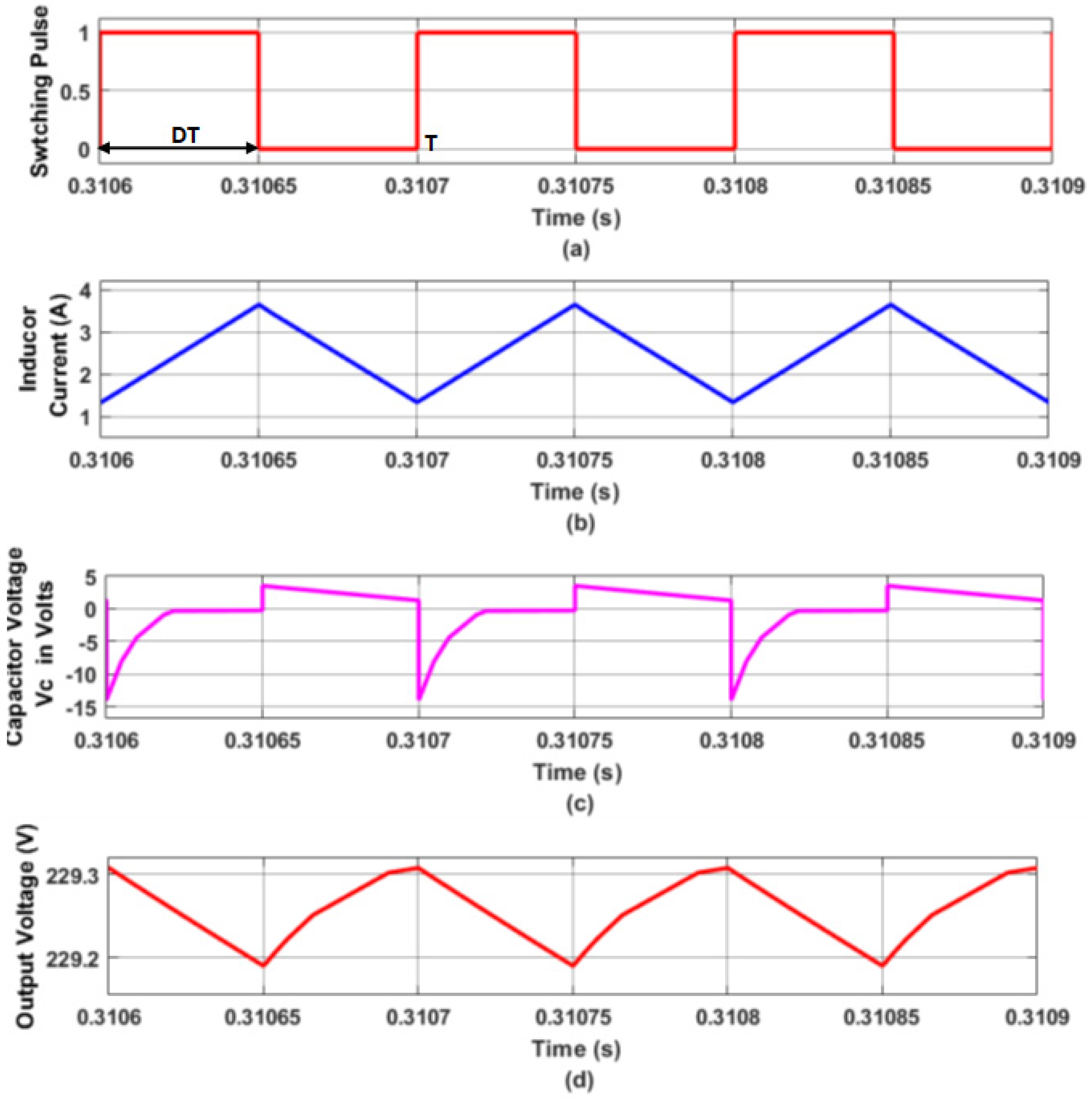
The variation of the current passing through inductor L1 and capacitor C and voltage across C0 for a switching cycle are shown in Figure 4.
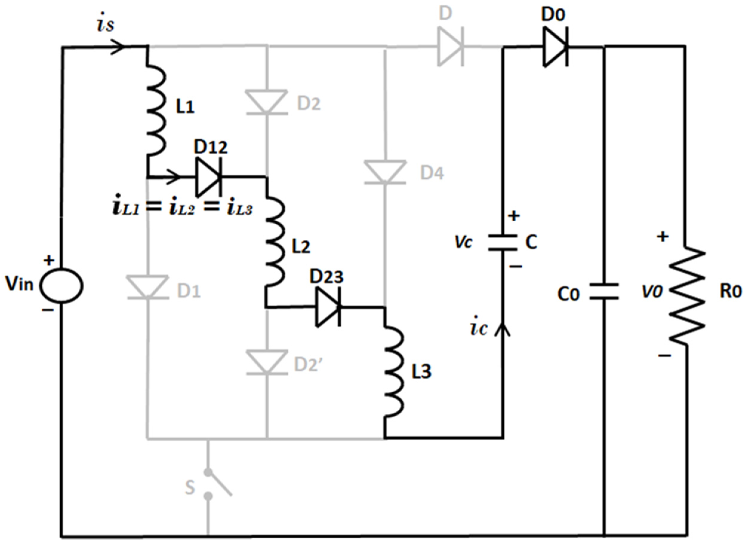
The equivalent circuit when the switch S is closed at t = 0 is shown in Figure 5. The inductors (L1, L2, L3) and capacitor (C), which are connected in parallel to the source, get charged. The load side capacitor (C0) discharges and supplies power to the load.
where T = Time period, D = Duty ratio and ton = DT
The voltage available across all the inductors is equal to input voltage
V i n = V L 1 = V L 2 = V L 3  
Vin = input voltage
During this interval, the capacitor is charged to input voltage Vin. The variation of iL, iC and vC are shown in Figure 4b,c,d, respectively.
  • Mode 1:
Figure 5. Mode 1 equivalent circuit during turn on time.
Sustainability 14 12296 g005
  • Mode 2:
The equivalent circuit when the switch S is opened is shown in Figure 6. The inductors (L1, L2, L3) and capacitor (C) start discharging. The load is supplied by the source and the discharging elements, parallelly the capacitor (C0), gets charged.
During the turn off time toff, the voltage across the capacitor is v0. Applying kvl to the circuit shown in Figure 6,
V L 1 = V L 2 = V L 3 = 2 V i n V o u t 3  
The variation of iL, vC and v0 are shown in Figure 4b,c,d, respectively.
Applying volt second balance equation across the inductor,
V L ( t o n ) + V L ( t o f f ) = 0  
[ V i n ( D T ) ] + [ ( 2 V i n V o u t 3 ) ( 1 D ) T ] = 0
Solving Equation (3),
V 0 V i n = 2 + D 1 D
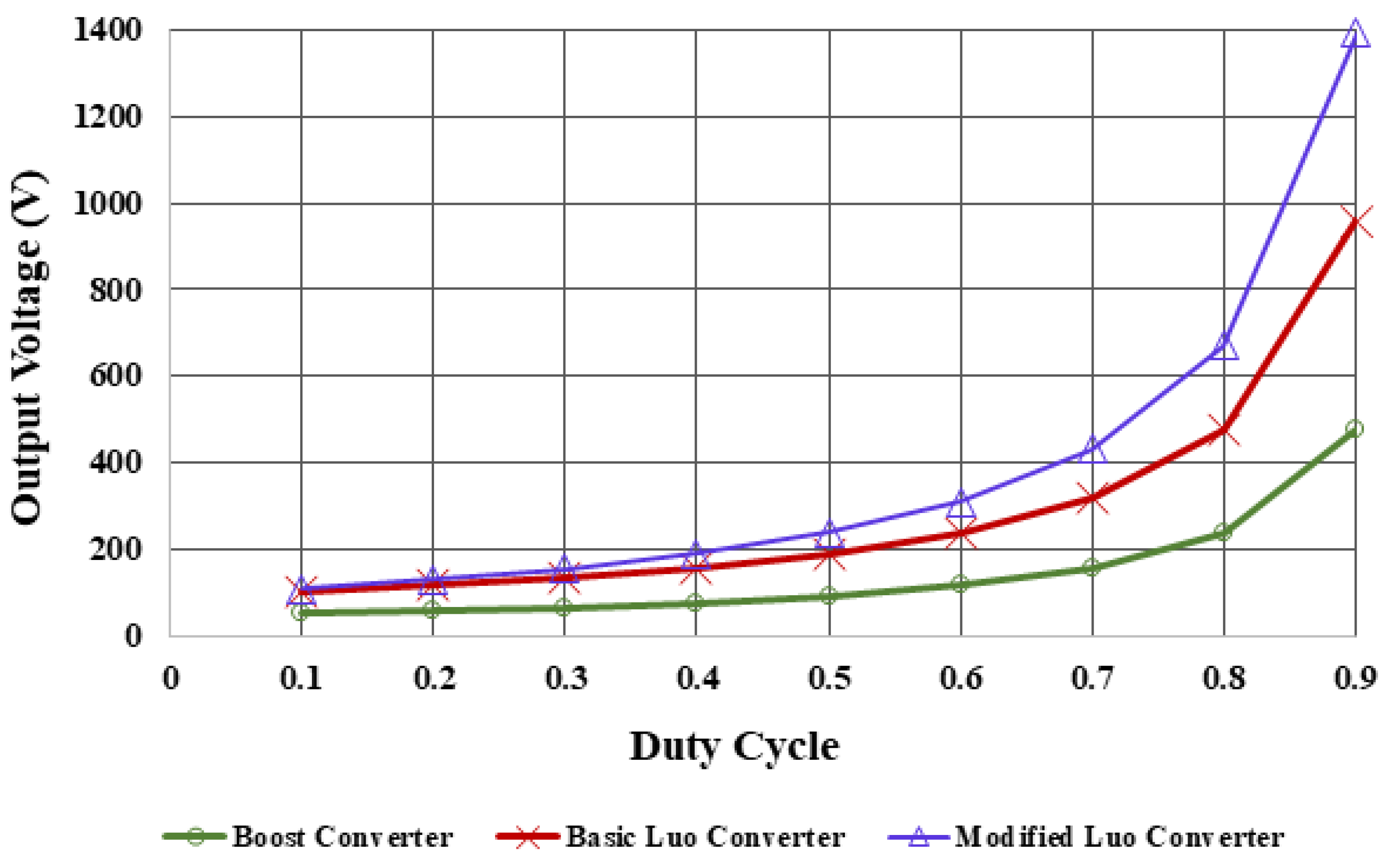
Figure 7 shows the variation of output voltage for a change in duty ratio of Boost converter, basic Luo and modified high gain Luo converters.
It is inferred that the magnitude of the output voltage obtained from high gain Luo converter is higher than the remaining converters for the same duty ratio. Hence, a modified high gain Luo converter is more suitable for lighting systems in commercial building applications.
The battery output is provided as the input to the modified Luo converter and it is designed to operate at 240 V, 500 W. The design specifications of this converter are given in Table 1. The only switch present in the modified Luo converter is operated through a closed loop control to maintain its output voltage constant at 240 V against the variation in the load current. The output of this modified Luo converter is directly connected to 5 parallel strings with each string of 10 LED lamps each with a rating of 24 V, 10 W.
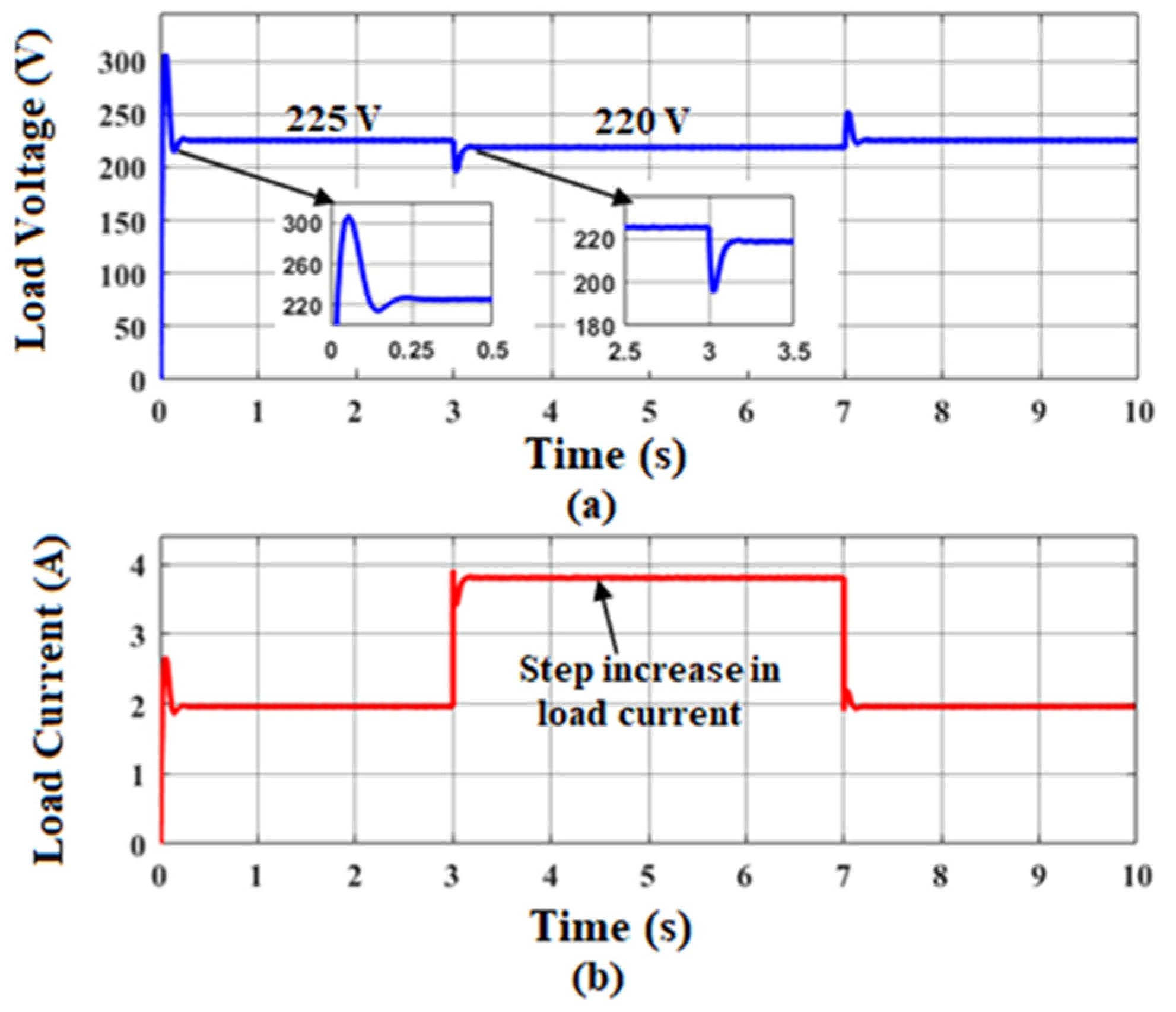
The open loop control of the modified Luo converter is created in MATLAB/Simulink® wherein the MOSFET switch is triggered with a pulse obtained from a pulse generator of 10 kHz frequency. A fixed duty ratio of 50% is selected in order to get 240 V DC output from 48 V DC input. The 48 V DC is obtained from the PV integrated battery energy storage system. The simulation results for open loop control are obtained for a standard test condition of 1000 W/m2 and 25 °C. From Figure 8, it is inferred that the desired output voltage is not attained for rated load conditions and it is decreased further due to step increase in load current. It is observed that the output voltage settles to 225 V at 0.3 s with an overshoot of 30.9% and a steady state error of 15 V. Hence, there is a need for the controller to maintain the rated output voltage irrespective of change in load conditions.

2.3. Modelling of the Modified Luo Converter

State-Space Modelling

The steady state analysis of the modified Luo converter can be done by developing a state-space model by assuming that it operates in continuous conduction mode. The source current (is) and capacitor voltage (vo) are considered as state variables.
The state model of the converter is represented by the following equations which comprise of state equations and output equation
x ˙ = A x + B u
y = C x
where A is the system matrix of order (2 × 2); B is the input matrix of order (2 × 1); and C is the output matrix of order (1 × 2). x is the state vector of order (2 × 1), u is the input vector of order (1 × 1) and y is the output vector of order (1 × 1).
The current passing through each inductor is represented as iL, assuming the current passing through all the three inductors are the same. The state-space model is developed for each switching state in a cycle.
  • Mode 1—(When the switch is closed) (0 to DT)
By applying Kirchhoff’s current law at node A in Figure 5, the following equations are obtained.
The source current
i s = i L 1 + i L 2 + i L 3
where iL1, iL2 and iL3 are the currents passing through inductors L1, L2 and L3, respectively.
As i L 1 = i L 2 = i L 3 are equal,
i s = 3 i L
Applied voltage V s = L 1 d i L 1 d t = L 2 d i L 2 d t = L 3 d i L 3 d t
V s = L 1 d ( i s / 3 ) d t = L 1 3 d i s d t
Hence,
d i s d t = i ˙ s = 3 V s L 1 = 3 V s L
Since, L 1 = L 2 = L 3 = L
Similarly, the current passing through the capacitor C0 is i c 0 = v 0 R
C 0 d v 0 d t = v 0 R
d v 0 d t = v 0 R C 0
v ˙ 0 = v 0 R C 0
Equations (9) and (10) are known as state equations.
[ i ˙ s v ˙ 0 ] = [ 0 0 0 1 R C 0 ]   [ i s v 0 ] + [ 3 L 0 ] V s
From Equation (11), the state matrix and the input matrix are given as follows:
A 1 = [ 0 0 0 1 R C 0 ]   B 1 = [ 3 L 0 ]  
  • Mode 2—(When the switch is opened) (DT to T)
Referring the equivalent circuit in Figure 6, Equation (12) is written by applying KVL
V s L 1 d i s d t L 2 d i s d t L 3 d i s d t + V s v 0 = 0
2 V s v 0 3 L d i s d t = 0
d i s d t = 2 V s v 0 3 L = 2 3 L V s 1 3 L v 0
i ˙ s = 2 3 L V s 1 3 L v 0
Applying KCL, the current passing through the capacitor C0 is
i c 0 = i s i 0
d v 0 d t = 1 C 0 i s v 0 R C 0
v ˙ 0 = 1 C 0 i s v 0 R C 0
Equations (13) and (15) in state equations form
[ i ˙ s v ˙ 0 ] = [ 0 1 3 L 1 C 0 1 R C 0 ]   [ i s v 0 ] + [ 2 3 L 0 ] V s
From Equation (16), the state matrix and the input matrix are as follows:
A 2 = [ 0 1 3 L 1 C 0 1 R C 0 ]   B 2 = [ 2 3 L 0 ]  
The state-space average matrix is calculated as follows:
A = A 1 D + A 2 ( 1 D ) ,       B = B 1 D + B 2 ( 1 D )
Substituting A1, A2, B1 and B2 in Equation (17)
A = [ 0 D 1 3 L 1 D C 0 1 R C 0 ] B = [ ( 7 D + 2 3 L ) 0 ]
Hence the state-space model is represented as
X ˙ = A X + B U
The duty ratio D changes due to the deviation of state variable values. These variations are represented as
x = X + x ^ ,   d = D + d ^ ,   u = U + u ^
Substituting (9) in (8) leads to the development of an averaged small signal state-space model as shown below.
d d t ( X + x ^ ) = A ( X + x ^ ) + B ( U + u ^ )
X ˙ + x ^ ˙ = [ A 1 ( D + d ^ ) + A 2 ( 1 ( D + d ^ ) ) ] [ X + x ^ ] + [ B 1 ( D + d ^ ) + B 2 ( 1 ( D + d ^ ) ) ] [ U + u ^ ]
From Equation (19), the steady state DC values are obtained by
X ˙ = [ A 1 D + + A 2 ( 1 D ) ] X + [ B 1 D + B 2 ( 1 D ) ] U
After removing the steady state DC values, the perturbed equation is written by considering only the linear and nonlinear terms as
x ^ . = A ¯ x ^ + B ¯ u ^ + E ¯ d ^
A ¯ —System matrix of linearized system of order 2 × 2
A ¯ = [ 0 D 1 3 L 1 D C 0 1 R C 0 ]
B ¯ —Input matrix of linearized system of order 2 × 1
B ¯ = [ ( 7 D + 2 3 L ) 0 ]
E ¯ —Control input matrix of linearized system of order 2 × 1
E ¯ = [ V 0 + 7 V s 3 L I s C 0 ]
d ^ —control input vector of order 1 × 1
x ^ —state vector of order 2 × 1
u ^ —Input vector of order 1 × 1
Hence the small signal model of the modified Luo converter is obtained as
[ i ^ ˙ s v ^ ˙ 0 ] = [ 0 D 1 3 L 1 D C 0 1 R C 0 ] [ i ^ s v ^ 0 ] + [ 7 D + 2 3 L 0 ] [ v ^ s ] + [ V 0 + 7 V s 3 L I s C 0 ] [ d ^ ]
The output equation is written as
[ v ^ 0 ] = [ 0 1 ] [ i ^ s d ^ ]
where C ¯ = output matrix of linearized system of order (1 × 2)
C ¯ = [ 0 1 ]
The above linearized model helps to obtain the control input to output voltage transfer function using
v ^ 0 d ^ = C ¯ [ S I A ¯ ] 1 B ¯
Using Equation (23), the control input to output voltage transfer function for the designed converter obtained using MATLAB® m file is shown in Equation (24).
v ^ 0 d ^ = 2.083 × 10 4 s + 1.92 × 10 8 s 2 + 17.36 s + 1.667 × 10 5
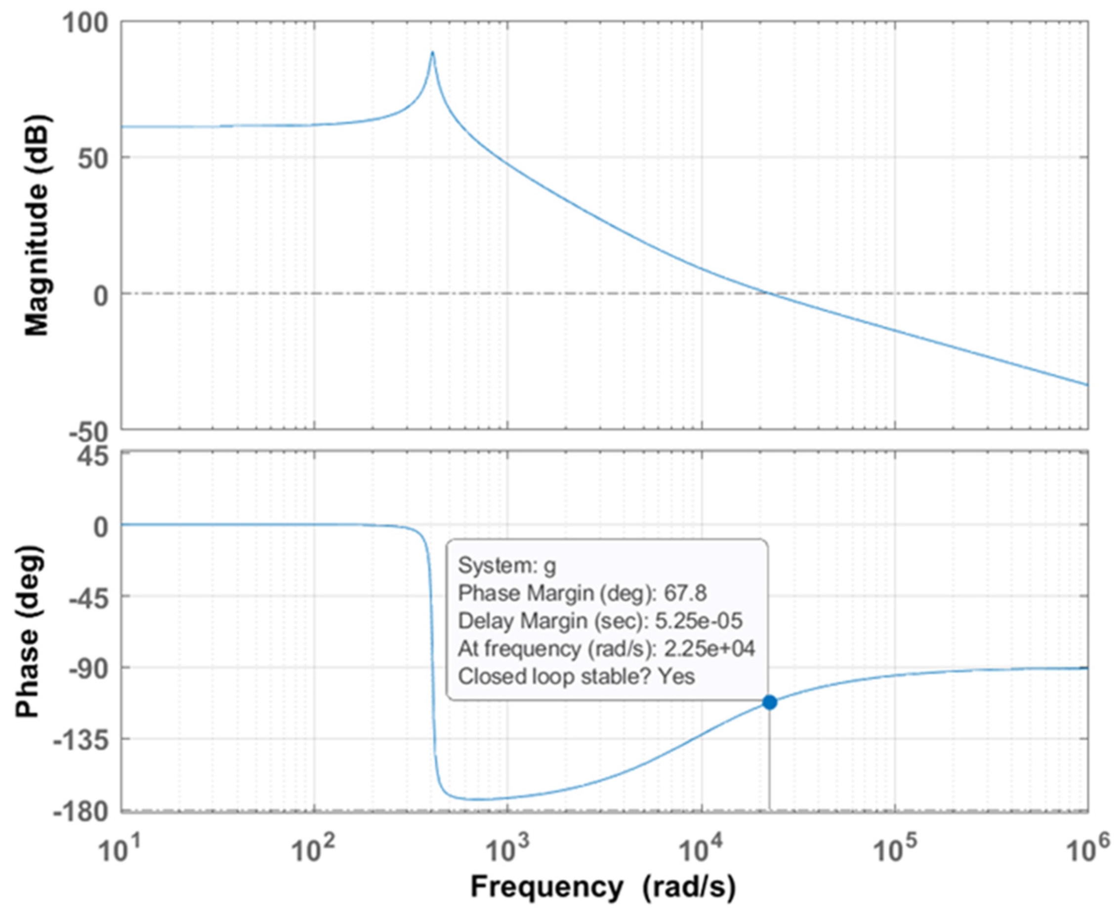
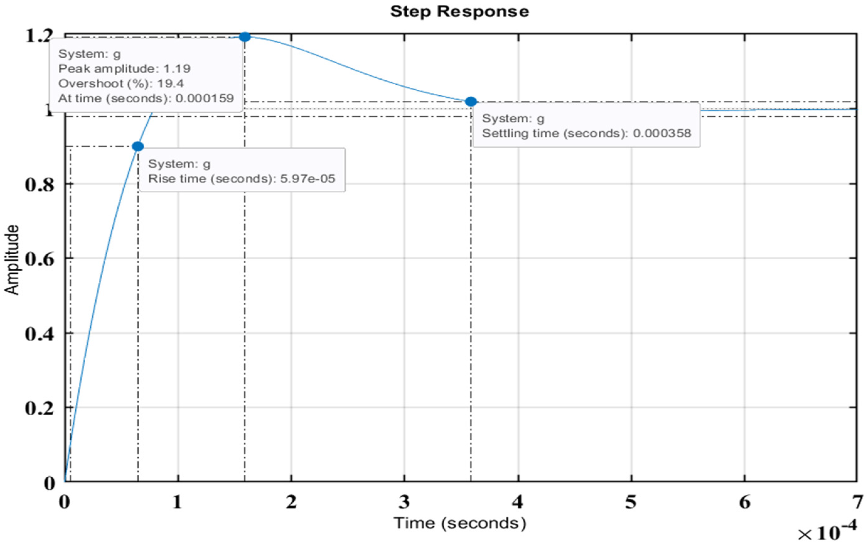
The Bode plot and time–domain response for unit step input are drawn for the transfer function in Equation (24) using MATLAB® m-file coding and are shown in Figure 9 and Figure 10, respectively.
It is inferred that the phase margin obtained from the plot is 67.8° and the output settles without steady state error, which reveals the stability of the system.

3. Results

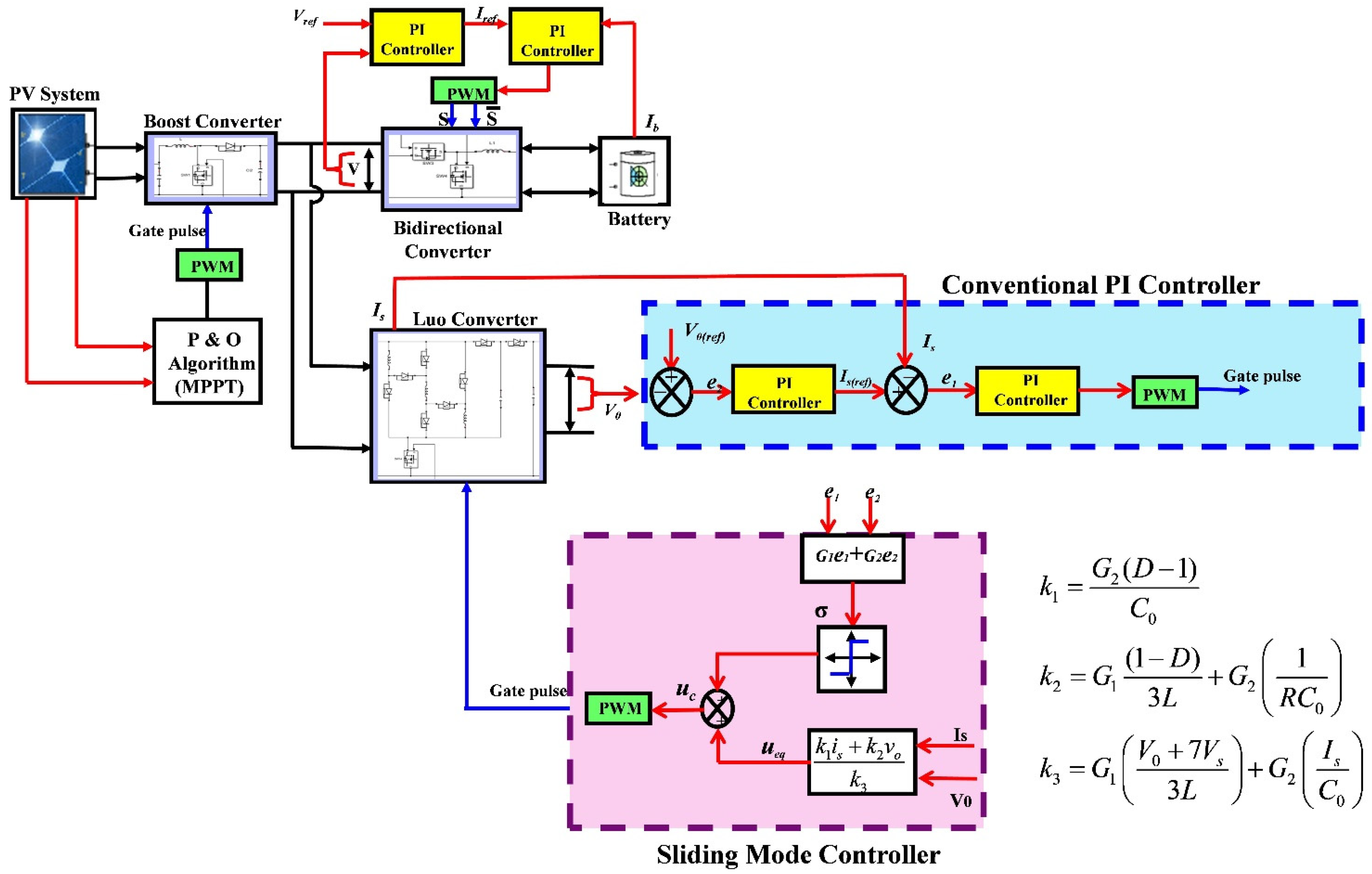
The proposed solar lighting for commercial system is developed using MATLAB/Simulink® software and represented in Figure 11, which consists of a PV integrated battery management system and modified Luo converter along with either a PI controller or SMC.

3.1. Analysis of the PV–BESS System

The PV integrated battery management system consists of an MPPT-based PV panel in which the P&O algorithm decides the duty ratio of the Boost converter so that maximum power can be extracted for the given irradiance and, correspondingly, the output voltage of the boost converter is obtained for a PV open circuit voltage of 37 V. Depending upon the magnitude of PV power and battery storage, the BMS works effectively to provide a constant voltage of 48 V to the Luo converter irrespective of change in irradiance. For achieving this objective, the bidirectional converter is designed for integrating the MPPT-based PV and battery. This converter is operated in buck mode when PV power is more than the load power and the battery is in charging condition. It is in boost mode when PV power is less than the load power and the battery starts discharging and supplying the load. The charging and discharging operating modes of the battery are obtained using PI controllers implemented in both outer voltage and inner current control loops. Hence, the BMS makes the PV-BESS system give a stable voltage of 48 V at different irradiance levels, which feeds the modified high gain Luo converter.
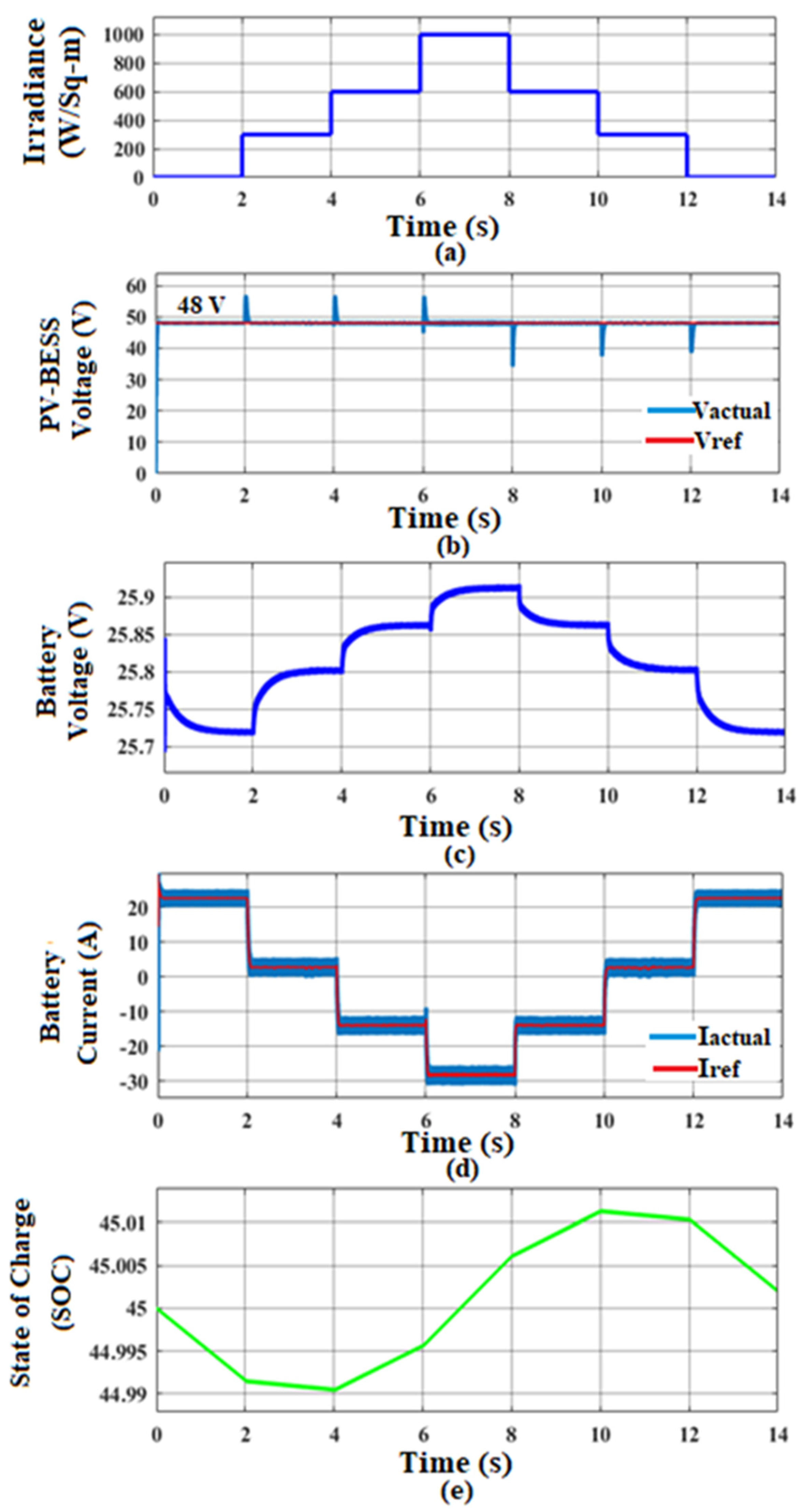
Figure 12 shows the constant output voltage of PV–BESS and parameters of the battery for step increase/decrease in insolation level for every 2 s duration. As the PV irradiance is zero for 0 to 2 s, the battery supplies the load and the discharging voltage of the battery is clearly shown in Figure 12c. For the time interval of 2 to 8 s, as the irradiance level is increased, the battery management system makes the battery charge and it become discharged for the remaining period as the insolation decreases, which is depicted from the waveforms shown in Figure 12d,e. Figure 12b shows output of the PV–BESS in which its magnitude is maintained constant irrespective of changes in irradiance.

3.2. Conventional PI Controller

As a commercial building needs a greater number of LED lamps to glow throughout the day, the modified high gain Luo converter is designed to increase the output voltage from PV–BESS to nearly five times in magnitude. In order to achieve regulated output voltage for wide range of load variation which occurs due to the frequent turn on/off of LED lamps, feedback control is employed for the modified Luo converter. To obtain the desired performance specifications during the transient period and to make zero steady state error, a linear PI controller is incorporated, which includes an inner current loop and outer voltage loop control. The actual load voltage is sensed and compared with a reference voltage of 240 V and the voltage error is processed in the PI controller and the output of this controller acts as the reference signal for the current. This current reference is compared with the actual input current of modified Luo converter and the resulting current error is the modulation signal of the Pulse Width Modulator (PWM). In the PWM block, the current error signal is compared with a high frequency triangular carrier waveform with a frequency of 10 kHz. The gate pulse of desired duty cycle received from PWM block triggers the controlled switch (S) of the Luo converter.
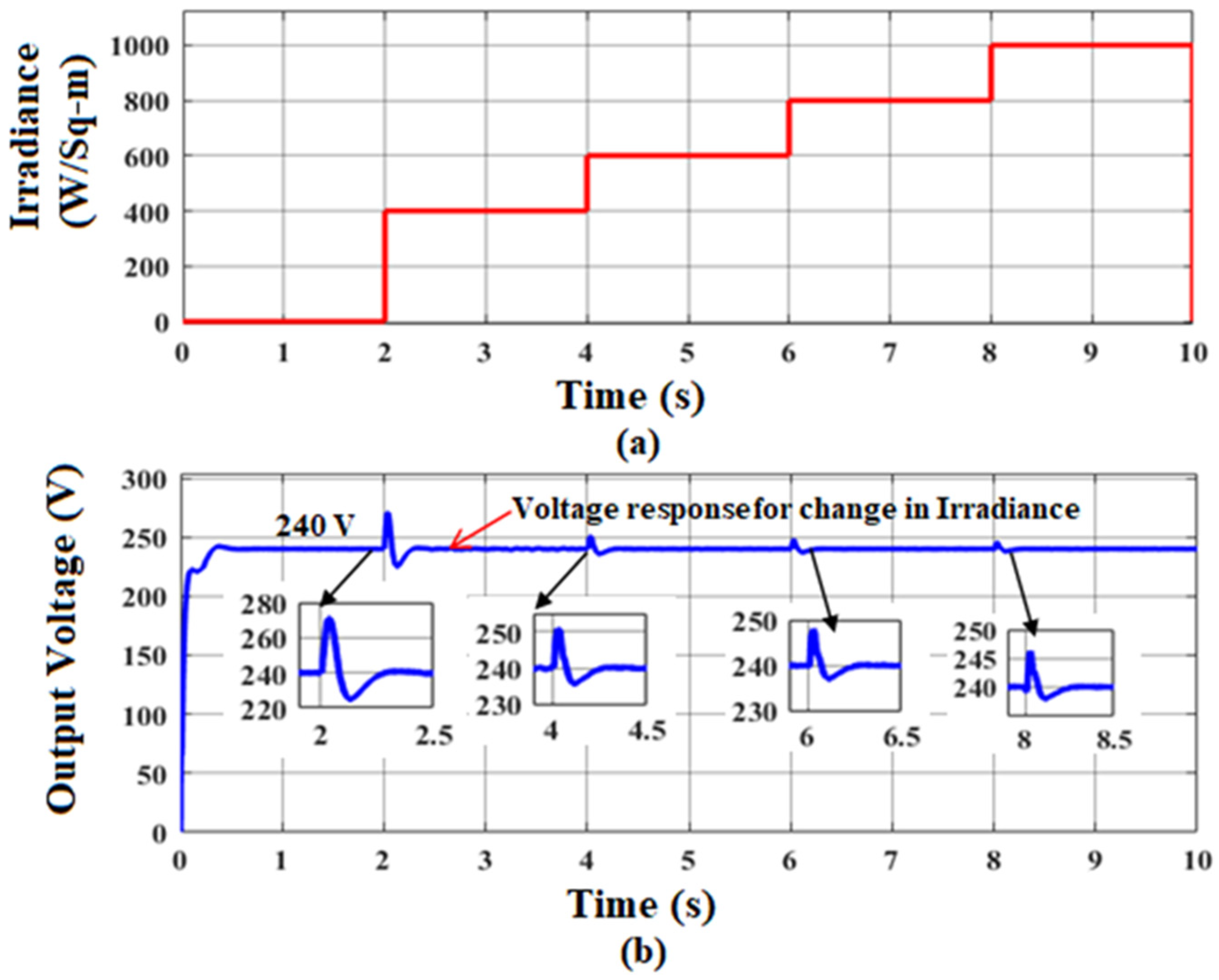
The Figure 13 shows the tracking capability of the PI controller for maintaining a constant output voltage of 240 V for a change in irradiance. It is clearly inferred from Figure 13b, for every step increase in irradiance as in Figure 13a, the output voltage settles down to the rated voltage of 240 V within a time period of 0.3 s with an overshoot ranging from 12.5% to 2.5%.
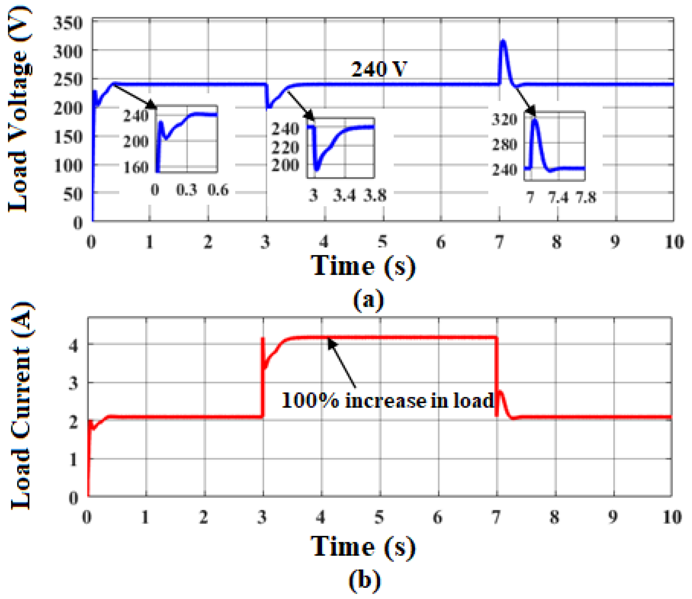
Figure 14 and Figure 15 show the robustness of the controller when there is a variation in load current as represented in Figure 14b and Figure 15b, which are obtained for a standard test condition of 1000 W/m2 and 25 °C. It is inferred from Figure 14a that the output settles to 240 V with an undershoot of 20.8% when the load current is increased to 100% from the rated value and it has an overshoot of 31.25% when the load current returns to rated value of 2.1 A. In both the conditions, the output voltage has a setting time of 0.4 s.
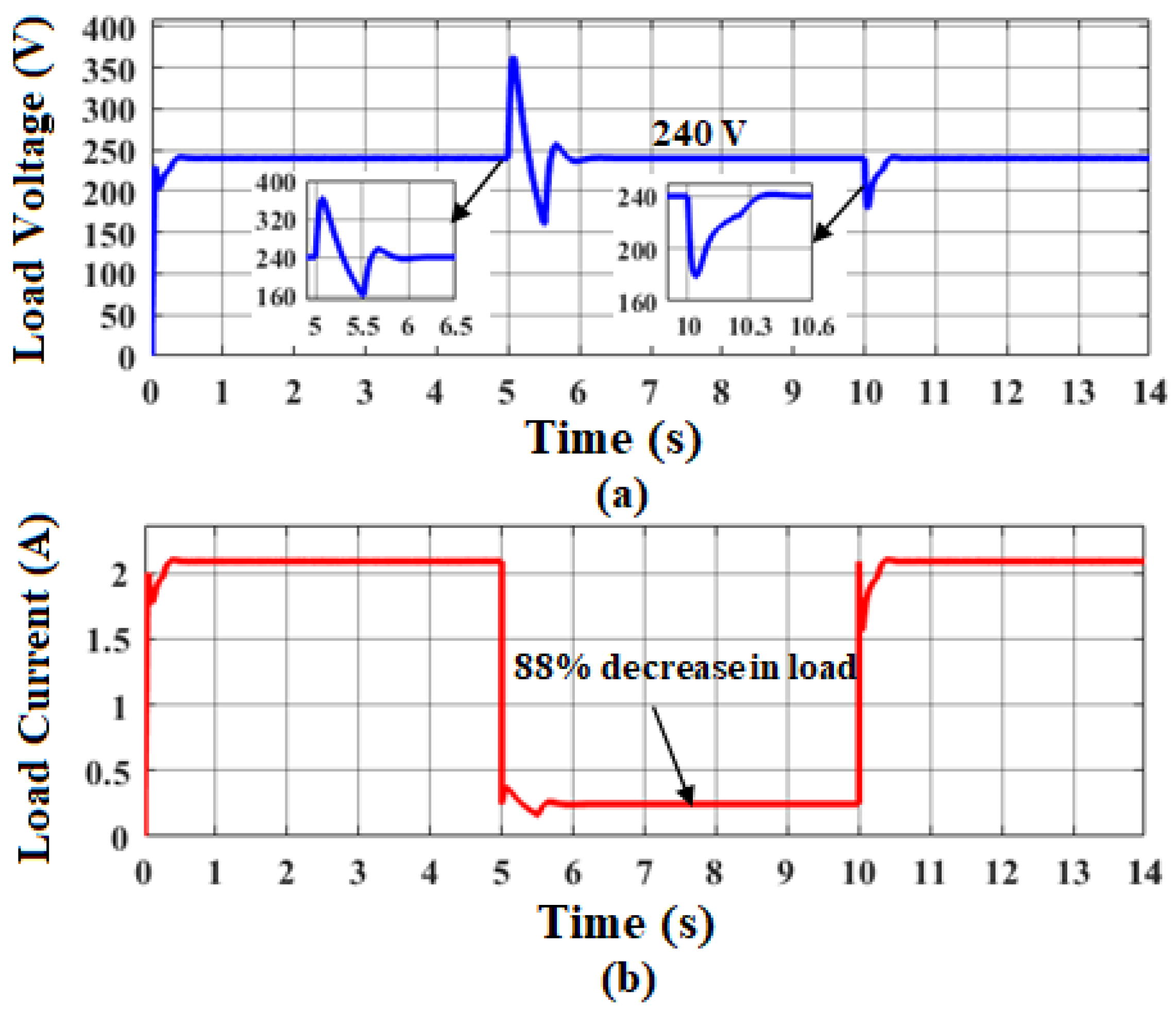
Similarly, Figure 15a shows the output voltage response which has an overshoot of 50% when there a decrease in the load current from the rated value of 2.1 A to 0.25 A and it takes a settling time of 1 s. When the load disturbance has been removed and comes to the rated value, the load voltage has an undershoot of 25% and a settling time of 0.5 s.
From the above analysis, it is inferred that the output voltage has appreciable overshoot and undershoot during the load current variations and also the decrease in load current from rated value is limited to 88%. To nullify these drawbacks, an SMC is designed.

3.3. Sliding Mode Controller

As the converter comes under non-linear type, a non-linear Sliding Mode Controller is chosen to provide precise tracking of output against load and line variations. It includes multiple state feedbacks and the desired closed loop response is obtained in time–domain directly. The state variables considered are source current error and output voltage error, which should be in analog form and accessible to the controller [25].
e 1 = w 1 x 1 = i s ( r e f ) i s
e 2 = w 2 x 2 = V r e f V 0
The sliding surface is fixed as a function of state variables with the help of sliding co- efficients G1 and G2 and represented in Equation (27)
σ ( e , t ) = [ G ] [ e ] = [ G 1 G 2 ] [ e 1 e 2 ]
The control component u helps to bring the system state variables to the sliding surface such that the σ = 0.
u = s i g n u m   ( σ )
σ ( e , t ) = [ G ] [ e ] = 0
To maintain the states of the system on the sliding surface against disturbances, the control component ueq is developed by differentiating Equation (29) with respect to time and equates to zero.
[ e ˙ ] = [ e ˙ 1 e ˙ 2 ] = [ w ˙ 1 x ˙ 1 w ˙ 2 x ˙ 2 ] = = [ i ˙ s ( r e f ) i ˙ s V ˙ r e f V ˙ 0 ] = [ x ˙ ]  
x ˙ = A x + E u e q
where
E = ( A 1 A 2 ) X + ( B 1 B 2 ) U = [ V 0 + 7 V s 3 L I s C 0 ]
σ ˙ ( e , t ) = [ G ] [ e ] = 0
[ G 1 G 2 ] [ x ˙ ] = 0
[ G 1 G 2 ] [ A x E u e q ] = 0
[ G 1 G 2 ] ( [ 0 ( 1 D ) 3 L ( D 1 ) C 0 1 R C 0 ] [ i s v 0 ] + [ ( V 0 + 7 V s ) 3 L I s C 0 ] u e q ) = 0
( G 1 [ ( 1 D ) 3 L ] v 0 ) + ( G 2 [ ( D 1 ) C 0 i s + 1 R C 0 v 0 ] ) + u e q ( G 1 ( V 0 + 7 V s ) 3 L G 2 I s C 0 ) = 0
u e q = ( G 2 ( D 1 ) C 0 ) i s + ( G 1 ( 1 D ) 3 L + G 2 1 R C 0 ) v 0 ( G 1 ( V 0 + 7 V s ) 3 L + G 2 I s C 0 )
Hence, the control signal from the controller should have two components, i.e.,
1.
u–to bring the system states to the sliding surface
2.
ueq–to maintain the system states on the sliding surface.
Hence, the continuous control component from the SMC, which is a modulating signal of the PWM block, is represented as
u c = u + u e q
G1 and G2 values are randomly selected as 0.07 and 1.18, respectively. The above algorithm is developed in the MATLAB/Simulink® tool and the obtained control signal is given to the PWM circuit.
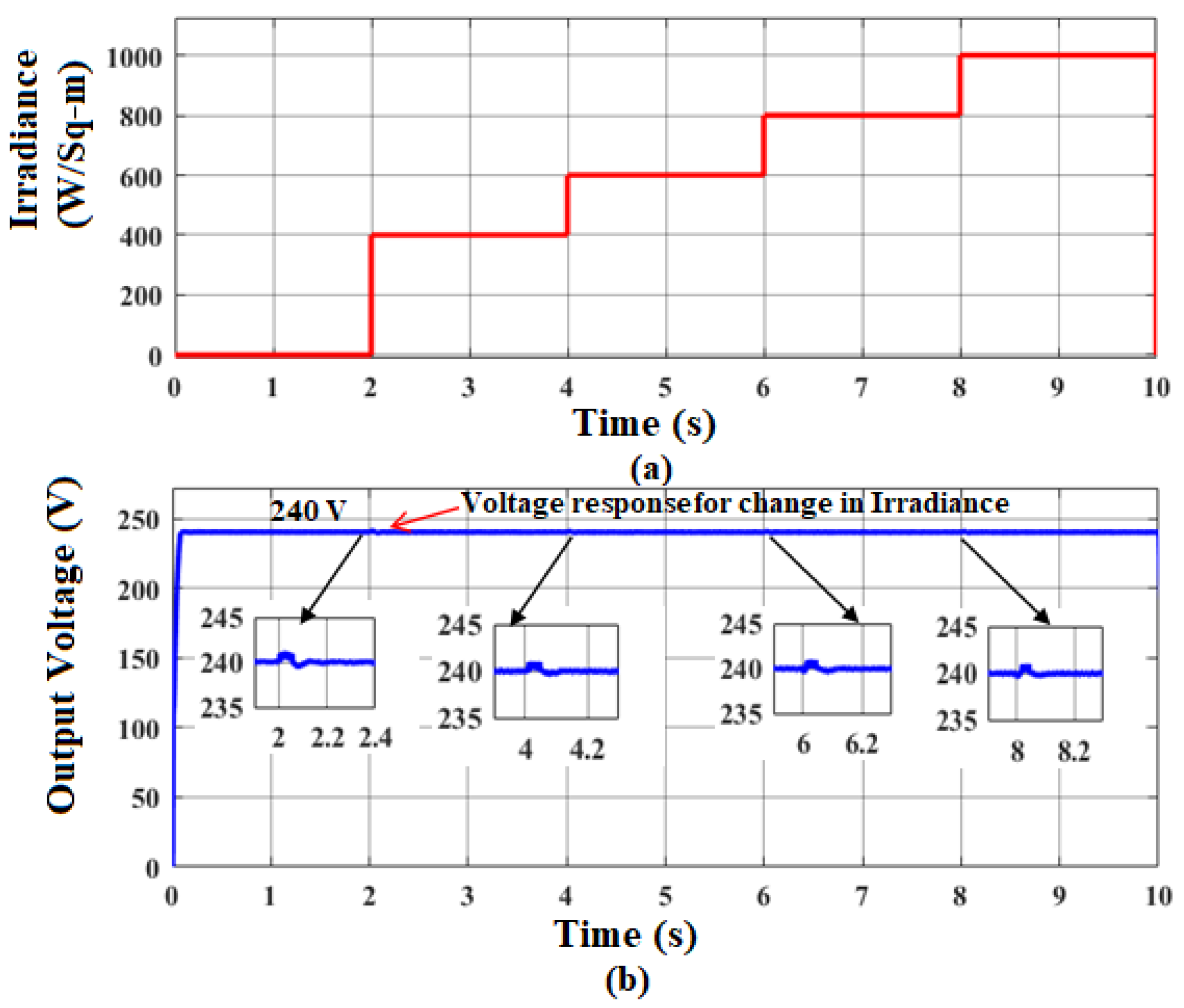
Figure 16 shows the tracking capability of an SMC for maintaining a constant output voltage of 240 V for change in irradiance. It is seen from Figure 16b, for every step increase in irradiance as in Figure 16a, the output voltage settles down to the rated voltage of 240 V within a time period of 0.1 s, with an average overshoot of 0.42%.
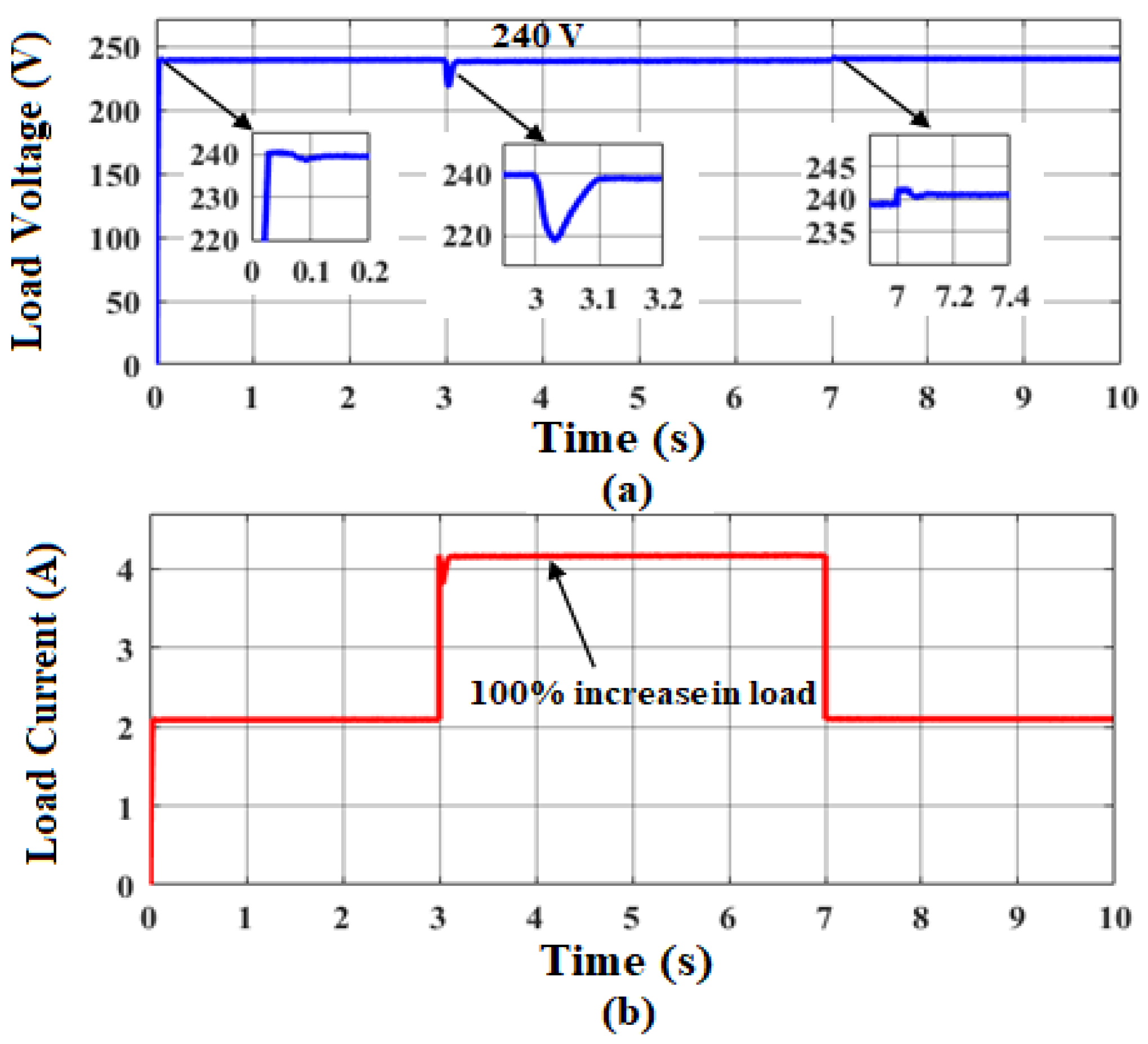
Figure 17 and Figure 18 show the effectiveness of the controller when there is a variation in load current as represented in Figure 17b and Figure 18b and the simulation results are obtained for a standard test condition of 1000 W/m2 and 25 °C. It is inferred from Figure 17b that the output voltage settles to 240 V with an undershoot of 8.33% when the load current is increased to 100% from the rated value and it has an overshoot of 0.833% when the load current returns to rated value of 2.1 A. In both the conditions, the output voltage has a setting time of 0.1 s.
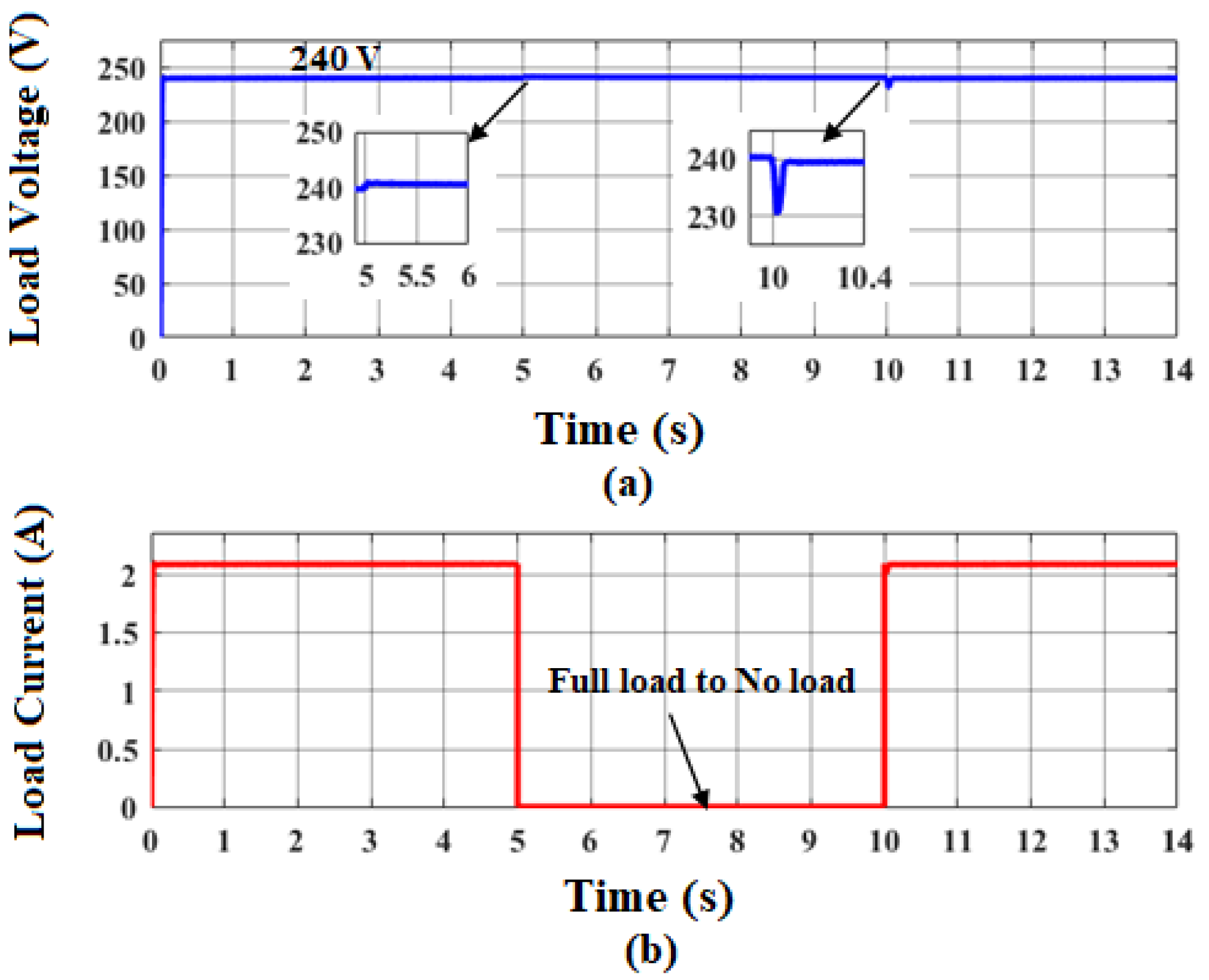
Similarly, Figure 18b shows the output voltage response which has an overshoot of 0.4% when there a decrease in the load current from a full load rated value to no load and it has a settling time of 0.2 s. When the load disturbance has been removed and comes to the rated value, the load voltage has an undershoot of 4.16% and a settling time of 0.1 s.
The exceptional performance of the SMC over the PI controller is emphasized as the output voltage has very minimal overshoot and undershoot at the instant of load current variations. From Figure 17 and Figure 18, the tracking capability of the SMC is proven even for a 100% increase and also a 100% decrease in load current from rated value, which was not seen in the literature discussed in this article.

4. Discussion and Performance Comparison

A PV–BESS integrated with high gain converter of rating 240 V, 500 W is designed such that it can handle a lighting system consisting of five parallel strings, each string having 10 LEDs. It is clearly shown from Figure 7 that the modified high gain Luo converter is better than Luo and Boost converters in terms of obtaining high gain at moderate duty cycles. From the literature review, it is seen that various topologies of high gain converter fed lighting systems are analyzed. These configurations include a greater number of passive circuit components and the existence of efficient feedback controls suitable for a wide range of load variation is also not addressed.
Hence, this research article is focused on designing a PV–BESS integrated high gain converter with a competent SMC which comes under the category of a non-linear controller as it provides defined stability and robustness against variations in system parameters as well as load uncertainties. To articulate the continuous control component of the SMC, the derived linearized small signal model is used and discussed, which is a new mathematical approach for this converter-fed lighting system. Moreover, a designed controller emphasizes its ability in satisfying the performance requirements in terms of minimal ripple voltage magnitude in %, which was not seen in previous works [17,19], and its tracking capability as per load requirements.
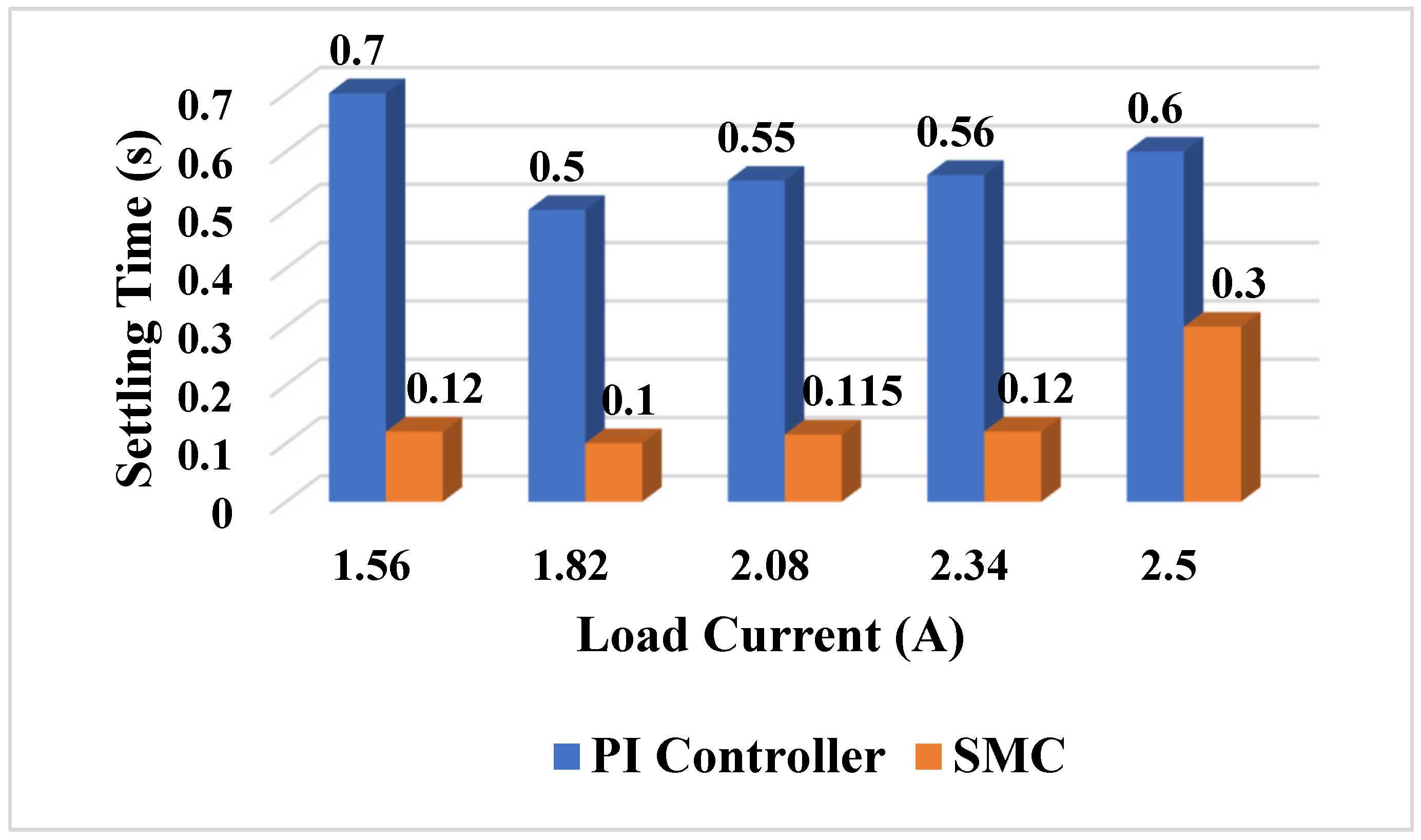
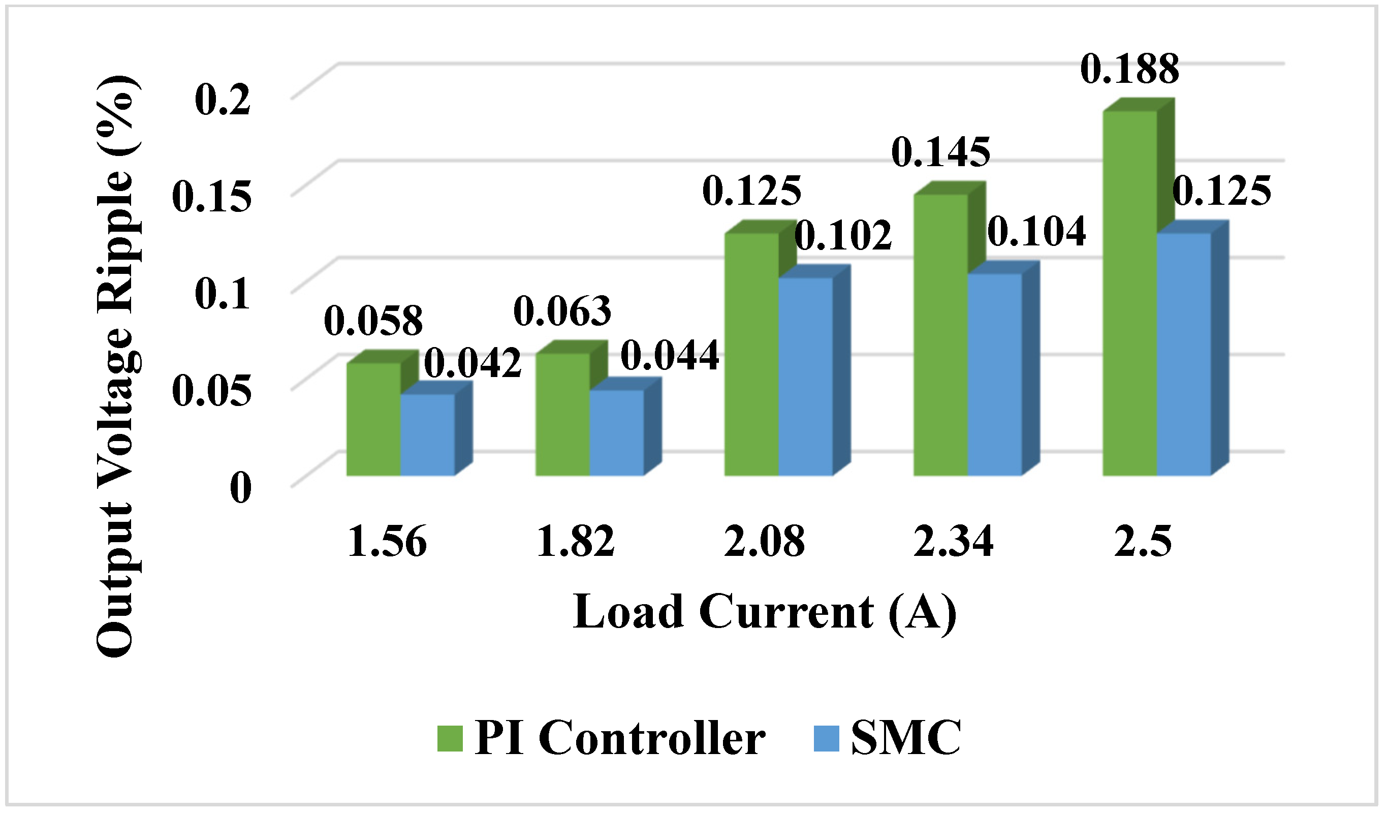
The performance of a PI Controller and an SMC in the presence of load current variations are compared in terms of % output voltage ripple and settling time by Figure 19 and Figure 20.
In Figure 19, settling time of the two controllers is compared for various load currents and it shows that the SMC outperforms the PI Controller in all loading conditions. A similar trend is seen in the voltage ripple for different loads, as shown in Figure 20. It can be concluded that performance of the nonlinear controller is superior to that of the linear controller in both transient and steady state conditions.

5. Conclusions

In recent years, DC microgrids are emerging as they are highly efficient, reliable and stable. Here, design and simulation of an integrated PV–BESS for lighting systems in a commercial building through a modified high gain Luo converter are presented. The P&O algorithm is implemented using a boost converter to extract the maximum power from the PV panel for the corresponding irradiance level. The bidirectional DC -DC converter used in BMS helps to control the charging and discharging of the battery, which leads to a constant output voltage of 48 V from PV–BESS and also provides a long battery life. To utilize this 48 V for 240 V, a 500 W LED lighting system is used in commercial building, and the modified high gain Luo converter is designed along with SMC for stepping up this 48 V to 240 V. To prove the preeminence of an SMC, a PI controller was also designed and a performance comparison was done between them.
The load regulatory analysis has been done to show the ability of both controllers for providing a stable output voltage over different loading conditions. The proposed scheme has been simulated using MATLAB/Simulink® and the obtained results are analyzed for various irradiance levels and load currents. From the results, it is inferred that the proposed scheme yields a very good solution for the lighting of a commercial building by utilizing solar energy.
The proposed system can be broadened to DC microgrids to provide eco-friendly power generation. Furthermore, there is an increase in different combination of loads in DC microgrids such as electric vehicles, computers, cooling fan, pumps etc. To supply these different types of loads, the nonlinear controller designed in this work is found to be a suitable choice for providing the regulated output voltage at different loading conditions. Provided, this article is formulated as a standalone generating unit for supplying an LED lighting system. If PV power is not available for a few days and the battery is also drained, then the load connected to the system will not get any supply. In such conditions, grid interactive PV–BESS is preferable.
Author Contributions

A.L.S., S.N. and U.D. conceptualized the problem, provided the methodology and analysis and prepared the original draft. N.P., Y.M.B. and M.S. reviewed and edited the manuscript and provided valuable insights in the overall system. All authors have read and agreed to the published version of the manuscript.

Funding

This research received no external funding.

Institutional Review Board Statement

Not applicable.

Informed Consent Statement

Not applicable.

Data Availability Statement

Data sharing not applicable.

Conflicts of Interest

The authors declare no conflict of interest.

References

  1. Makarabbi, G.; Gavade, V.; Panguloori, R.B.; Mishra, P.R. Compatibility and Performance Study of Home Appliances in a DC Home Distribution system. In Proceedings of the IEEE International Conference on Power Electronics, Drives and Energy Systems (PEDES), Mumbai, India, 16–19 December 2014. [Google Scholar]
  2. Panguloori, R.B.; Mishra, P.R.; Boeke, U. Economic Viability Improvement of Solar Powered Indian Rural Banks through DC Grids. In Proceedings of the Annual IEEE India Conference (INDICON), Hyderabad, India, 16–18 December 2011. [Google Scholar]
  3. Arunkumar, G.; Elangovan, D.; Sanjeevikumar, P.; Nielsen, J.B.H.; Leonowicz, Z.; Joseph, P.K. DC Grid for Domestic Electrification. Energies 2019, 12, 2157. [Google Scholar]
  4. Fotopoulo, M.; Rakopoulos, D.; Trigkas, D.; Stergiopoulos, F.; Blanas, O.; Voutetakis, S. State of the Art of Low and Medium Voltage Direct Current (DC) Microgrids. Energies 2021, 14, 5595. [Google Scholar]
  5. Oliver, J.S.; David, P.W.; Balachandran, P.K.; Mihet-Popa, L. Analysis of Grid-Interactive PV-Fed BLDC Pump Using Optimized MPPT in DC–DC Converters. Sustainability 2022, 14, 7205. [Google Scholar]
  6. Vieira, J.A.B.; Mota, A.M. Implementation of a Stand-Alone Photovoltaic Lighting System with MPPT Battery Charging and LED Current Control. In Proceedings of the 2010 IEEE International Conference on Control Applications (CCA), Yokohama, Japan, 8–10 September 2010; pp. 185–190. [Google Scholar]
  7. Basics of Light and Lighting. Available online: https://images.philips.com/is/content/PhilipsConsumer/PDFDownloads/China/ODLI20150914_001-UPD-zh_CN-basics_of_light.pdf (accessed on 20 June 2022).
  8. Iturriaga-Medina, S.; Martinez-Rodriguez, P.R.; Juarez-Balderas, M.; Sosa, J.M.; Limones, C.A. A Buck Converter Controller Design in an Electronic Drive for LED Lighting Applications. In Proceedings of the IEEE International Autumn Meeting on Power, Electronics and Computing (ROPEC), Ixtapa, Mexico, 4–6 November 2015; pp. 1–5. [Google Scholar]
  9. The Advantages of LED Lights for the Environment. Available online: https://www.sepco-solarlighting.com/ (accessed on 20 June 2022).
  10. Mohan, N.; Undeland, T.; Robbins, W. Power Electronics: Converters, Applications and Design, 3rd ed.; Wiley: New York, NY, USA, 2003. [Google Scholar]
  11. Shalini, K.; Glady, J.B.P. Solar Powered Luo Converter for Wiper Motor Application. Indian J. Sci. Technol. 2016, 9, 43. [Google Scholar] [CrossRef] [Green Version]
  12. Saravanan, S.; Babu, N.R. Maximum power point tracking algorithms for photo-voltaic system—A review. Renew. Sustain. Energy Rev. 2016, 57, 197–204. [Google Scholar]
  13. Liu, F.; Duan, S.; Liu, F.; Liu, B.; Kang, Y. A variable step size INC MPPT method for PV systems. IEEE Trans. Ind. Electron. 2008, 55, 2622–2628. [Google Scholar]
  14. John, R.V.; Gautam, R.; Kumar, M. Power Flow Management and BESS Design Consideration for Solar PV fed Isolated DC Microgrid for Residential Applications. In Proceedings of the IEEE Delhi Section Conference (DELCON), New Delhi, India, 11–13 February 2022. [Google Scholar]
  15. Liang, T.J.; Lee, J.H.; Chen, S.M.; Chen, J.F.; Yang, L.S. Novel isolated high- step-up DC–DC converter with voltage lift. IEEE Trans. Ind. Electron. 2013, 60, 1483–1491. [Google Scholar]
  16. Luo, F.L.; Ye, H. Power Electronics Advanced Conversion Technologies; CRC Press: Boca Raton, FL, USA, 2017. [Google Scholar]
  17. Soltani, B.A.; Sabahi, M.; Babaei, E.; Pouladi, J. Two-input boost converter for street-lighting applications. Comput. Electr. Eng. 2021, 92, 107126. [Google Scholar]
  18. Padmavath, P.; Sudhakar, N. Solar Powered LED Lighting with High Gain Boost Converter. J. Green Eng. 2018, 8, 411–430. [Google Scholar]
  19. Yalla, T.R.P.; Rajendran, V. A Novel Hybrid High Gain DC-DC Converter for Renewable Energy Applications. Int. J. Renew. Energy Res. 2022, 12, 1. [Google Scholar]
  20. Mansour, A.S.; Amer, A.L.H.H.; el Kholy, E.E.; Zaky, M.S. High gain DC/DC converter with continuous input current for renewable energy applications. Sci. Rep. 2022, 12, 12138. [Google Scholar]
  21. Asl, A.A.; Asl, R.A.; Hosseini, S.H. A New PV/FC/Battery DC-DC Converter. In Proceedings of the 13th Power Electronics, Drive Systems, and Technologies Conference (PEDSTC), Tehran, Iran, 1–3 February 2022. [Google Scholar]
  22. Kumar, K.R.; Jayaudhaya, J.; Tamilselvan, V.; Balakumar, S. Design of Hybrid Posicast Control for Super-Lift Luo Converter. Hindawi Math. Probl. Eng. 2022, 12, 1760861. [Google Scholar]
  23. Femia, N.; Petrone, G.; Spagnuolo, G.; Vitelli, M. Optimization of perturb and observe maximum power point tracking method. IEEE Trans. Power Electron. 2005, 20, 963–973. [Google Scholar]
  24. Berkovich, Y.; Axelrod, B.; Madar, R.; Twina, A. Improved Luo converter modifications with increasing voltage ratio. IET Power Electron. 2015, 8, 202–212. [Google Scholar]
  25. Subashini, N.; Augusti Lindiya, S.; Vijayarekha, K.; Ramkumar, K. Performance analysis of sliding mode controlled bridgeless interleaved boost converter for battery charging applications. Control. Eng. Appl. Inform. 2019, 21, 20–30. [Google Scholar]
Figure 1. Functional Block diagram.
Sustainability 14 12296 g001
Figure 2. (a) I-V (b) P-V characteristics.
Sustainability 14 12296 g002
Figure 3. Modified Luo converter.
Sustainability 14 12296 g003
Figure 4. Waveforms of modified Luo converter: (a) Switching pulse (b) Inductor current (c) Capacitor voltage (d) Output voltage.
Sustainability 14 12296 g004
Figure 6. Mode 2 equivalent circuit.
Sustainability 14 12296 g006
Figure 7. Output Voltage vs. Duty Cycle.
Sustainability 14 12296 g007
Figure 8. Simulation Results of modified Luo converter in open loop control: (a) Load voltage (b) Load current.
Sustainability 14 12296 g008
Figure 9. Bode plot for stability analysis.
Sustainability 14 12296 g009
Figure 10. Transient and steady state response of the system for unit step input.
Sustainability 14 12296 g010
Figure 11. Simulink model of the entire scheme.
Sustainability 14 12296 g011
Figure 12. Simulation Results of PV-BESS: (a) Irradiance (b) PV-BESS voltage (c) Battetry voltage (d) Battery current (e) State of Charge.
Sustainability 14 12296 g012
Figure 13. Dynamic response of modified Luo converter with PI controller: (a) Change in irradiance (b) Output voltage with respect to irradiance change.
Sustainability 14 12296 g013
Figure 14. Performance of modified Luo converter with PI controller for 100% step increase in load: (a) Load voltage response (b) Load current response.
Sustainability 14 12296 g014
Figure 15. Performance of modified Luo converter with PI controller for step decrease in load: (a) Load voltage response (b) Load current response.
Sustainability 14 12296 g015
Figure 16. Dynamic response of modified Luo converter with SMC: (a) Change in irradiance (b) Output voltage with respect to irradiance change.
Sustainability 14 12296 g016
Figure 17. Performance of modified Luo converter with SMC for 100% step increase in load: (a) Load voltage response (b) Load current response.
Sustainability 14 12296 g017
Figure 18. Performance of modified Luo converter with SMC for 100% step decrease in load: (a) Load voltage response (b) Load current response.
Sustainability 14 12296 g018
Figure 19. Comparison of Output Voltage Settling Time with PI Controller and SMC.
Sustainability 14 12296 g019
Figure 20. Comparison of Output Voltage ripple with PI Controller and SMC.
Sustainability 14 12296 g020
Table 1. Specifications of modified Luo converter.
ParametersValues
Input Voltage (Vin)48 V
Inductor (L = L1 = L2 = L3)1 mH
Capacitor (C)100 µF
Output Capacitor (C0)500 µF
Switching Frequency (fsw)10 kHz
Output Voltage (V0)240 V
Output power (P0)500 W
Duty Ratio0.5
Publisher’s Note: MDPI stays neutral with regard to jurisdictional claims in published maps and institutional affiliations.