
Recent Developments and Advancements in Solar Air Heaters: A Detailed Review

 ,
, 
 ,
,  ,
,  ,
,  ,
, 

Abstract
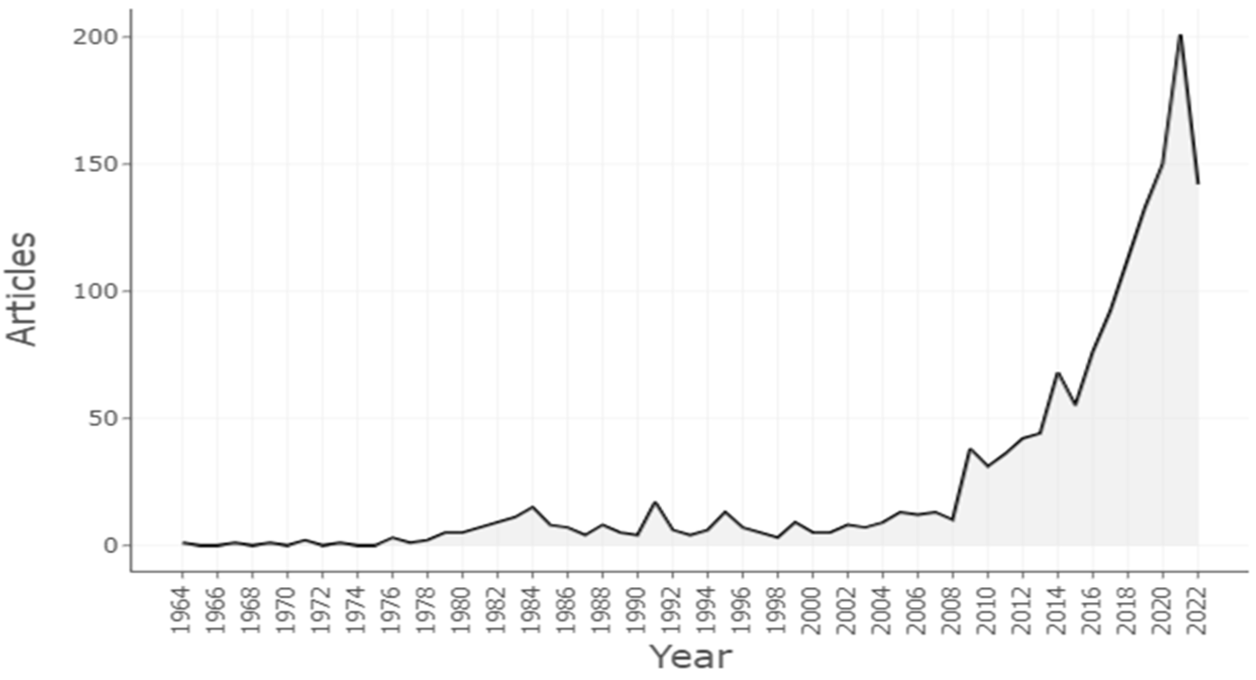
1. Introduction
1.1. Helio-Thermal Technology (Solar Collectors)
1.2. Solar-Collecting System
- (a)
- High-temperature system (ΔT > 400 °C)
- Parabolic dish-collector
- Dish-sterling system
- Central receiver system
- (b)
- Medium-temperature system (ΔT = 400 °C)
- Line-focusing parabolic collector
- (c)
- Low-temperature system (ΔT = 100 °C)
- Flat-plate collector
- Solar pond
- Solar-updraft tower
1.3. Low-Temperature System (ΔT = 100 °C)
1.4. Flat-Plate Solar-Collecting System
1.5. Solar Air Heating
2. Research Objectives
3. Solar Air-Heater Classification
3.1. Single-Pass SAH
3.2. Double-Pass SAH
3.2.1. Parallel-Flow SAH
3.2.2. Counter-Flow DPSAH
3.2.3. Recycle or Counter-Flow DPSAH
3.2.4. Multi-Pass Solar Air Heater
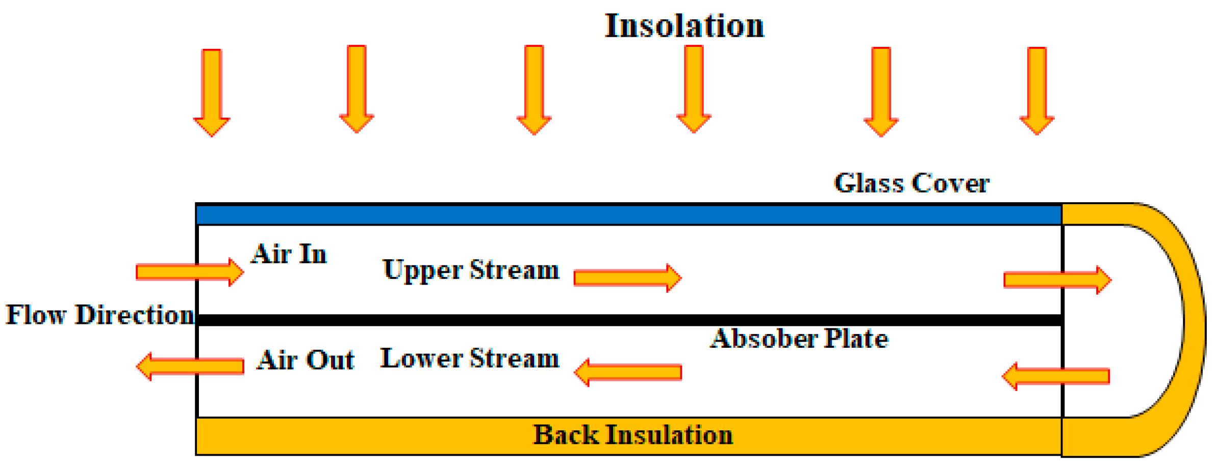
4. Experimental Setup
5. Thermal Performance of Flat-Plate SAH
- Qu = useful heat gain, W/m2;
- Ut = total loss coefficient, W/m2K;
- Tpm = average plate temperature, K;
- Ta = ambient temperature, K.
6. Heat Transfer in Conventional (Smooth) Collectors
- L = collector length and b = thickness of the air duct.
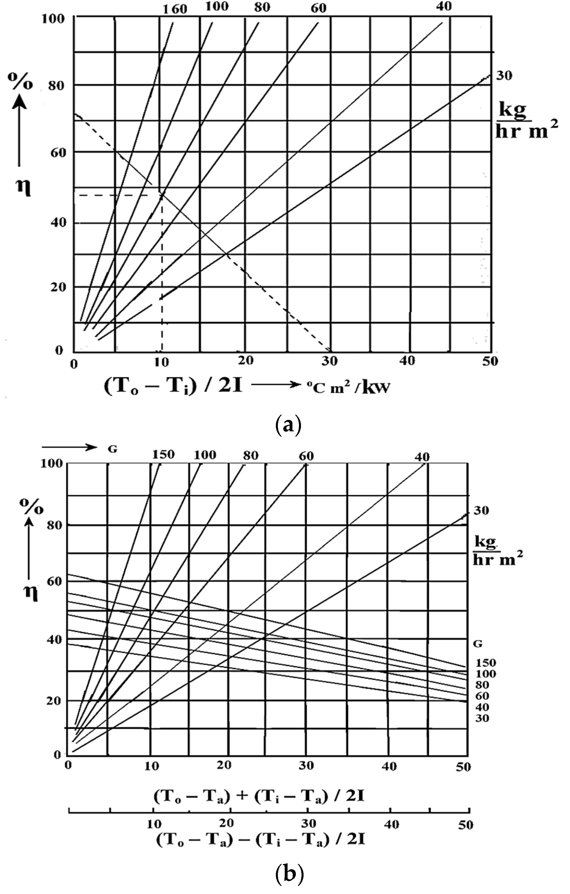
7. Testing of Solar Air Collector
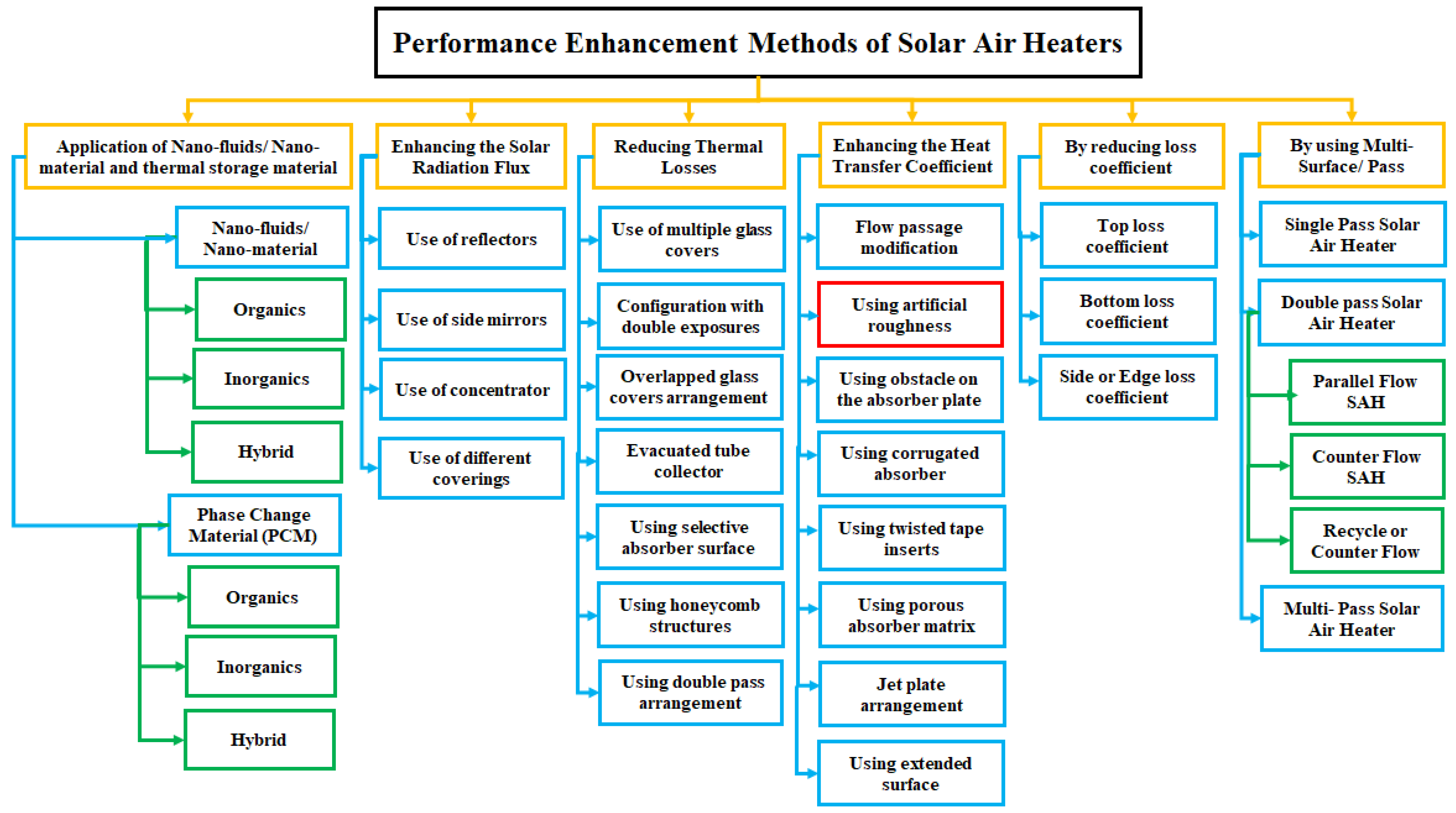
8. Performance-Enhancement Methods of Solar Air Heaters
8.1. Application of Nanofluids and Thermal Storage Material
8.2. Enhancing the Solar-Radiation Flux
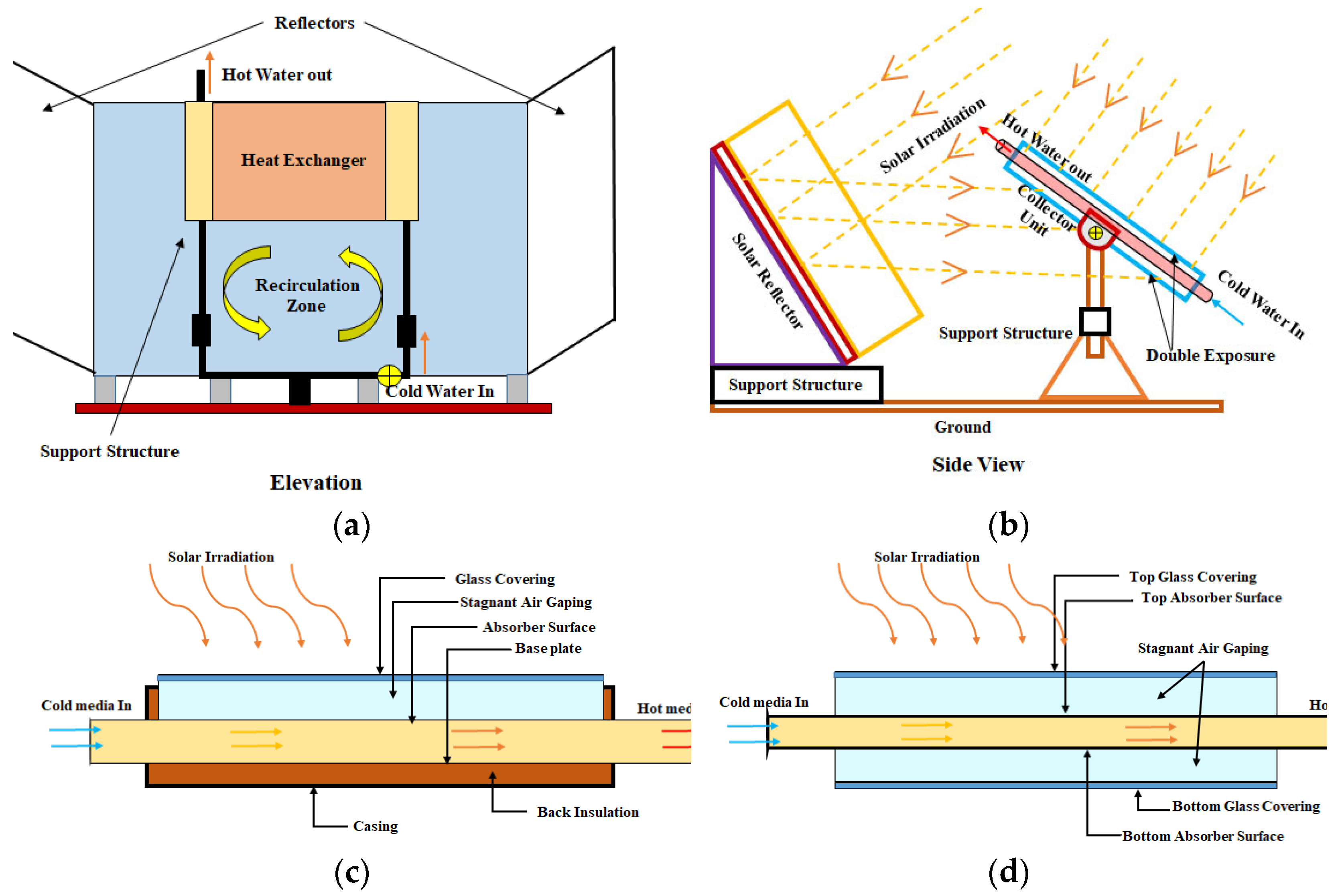
Use of Reflectors
8.3. Reducing Thermal Losses
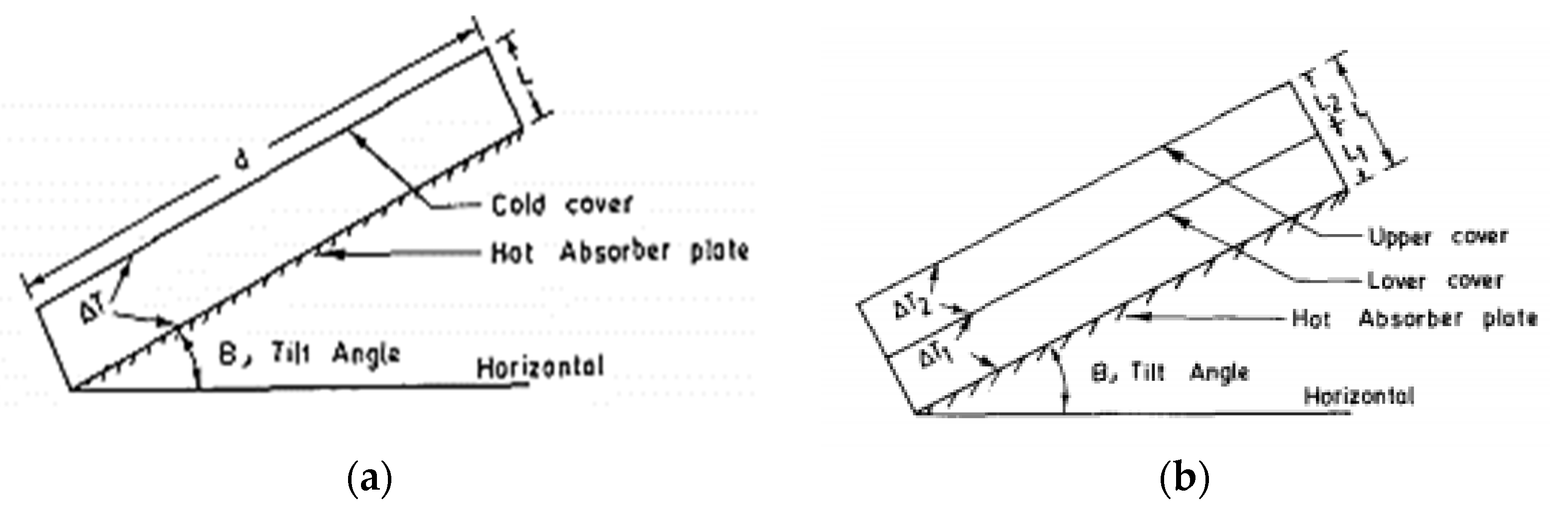
8.3.1. Use of Multiple Glass Covers
8.3.2. Configuration with Double-Exposure Orientation
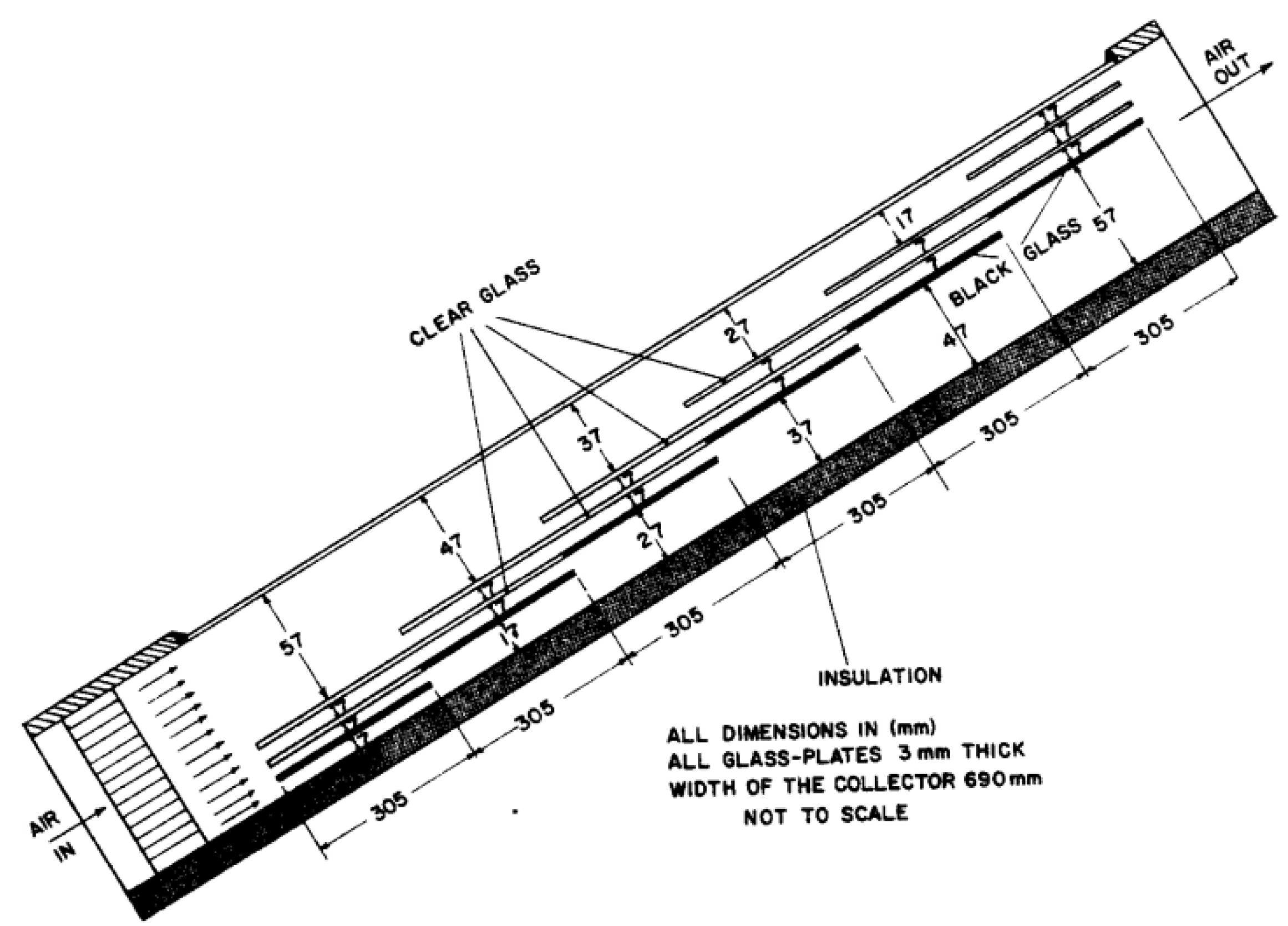
8.3.3. Overlapped Glass-Cover Arrangement
8.3.4. Evacuated Tube Collector
8.3.5. Using Selective Absorber Surface
8.3.6. Using Honeycomb Structures
8.3.7. Using Double-Pass Arrangement
8.4. By Reducing Loss Coefficient
8.4.1. Evaluation of Loss Coefficients
Top-Loss Coefficient
- Ng is the number of glass covers;
- for use ;
- Tp = averane plate temperature, K;
- B = collector tilt angle, o;
- hw = convective heat-transfer coefficient, W/m2-K;
- εp = absorbing-plate emissivity;
- εp = glass-cover emissivity;
- σ = Stefan–Boltzman constant (5.6697 × 10⁻⁸, W/m2K4)
Bottom-Loss Coefficient
Side- or Edge-Loss Coefficient
8.5. Enhancing the Heat-Transfer Coefficient
8.5.1. Jet-Plate Arrangement
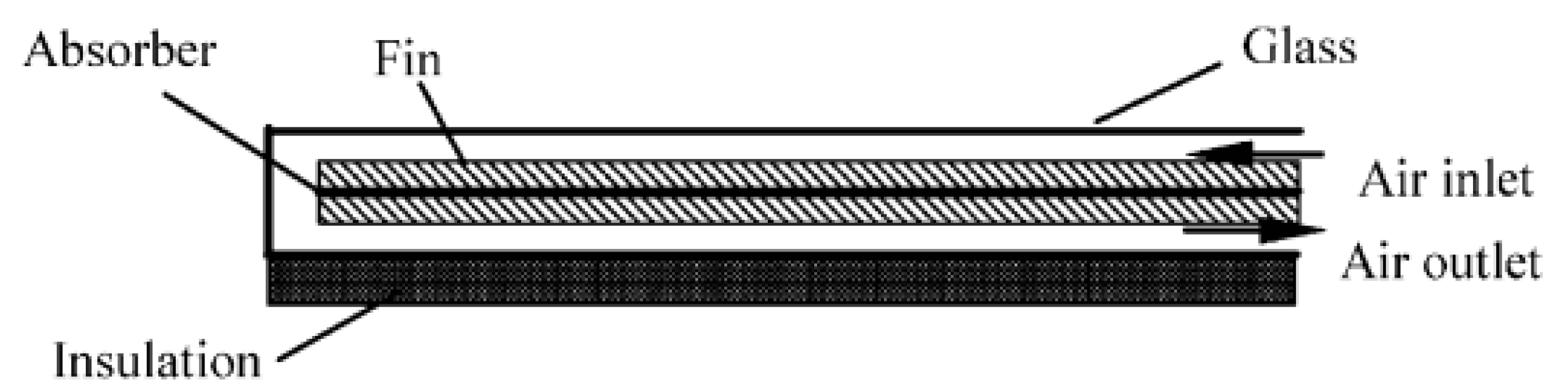
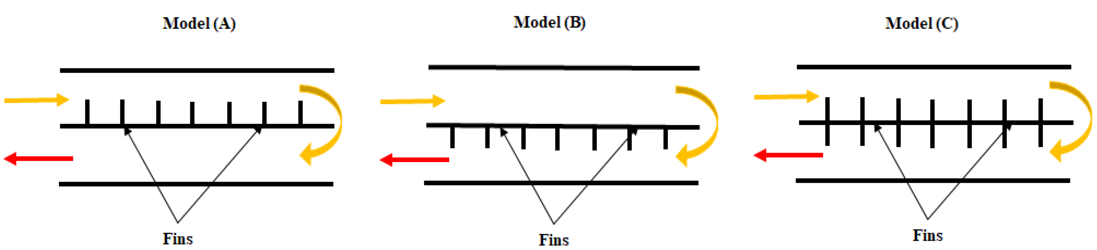
8.5.2. Using Extended Surface
8.5.3. Using Obstacles on the Absorber Plate
8.5.4. Using Corrugated Absorber
8.5.5. Using Twisted-Tape Inserts
8.5.6. Using Porous Absorber Matrix (Packed Duct)
8.5.7. Using Artificial Roughness
9. Artificial Roughness and Its Repercussions
10. Investigations of Different Types of Artificial Roughness
11. Effectiveness of Geometry and Operating Parameters of Artificial Roughened SAH
11.1. Effect of Absorber-Roughness Parameters
11.1.1. Effect of Relative Roughness Pitch (P/e)
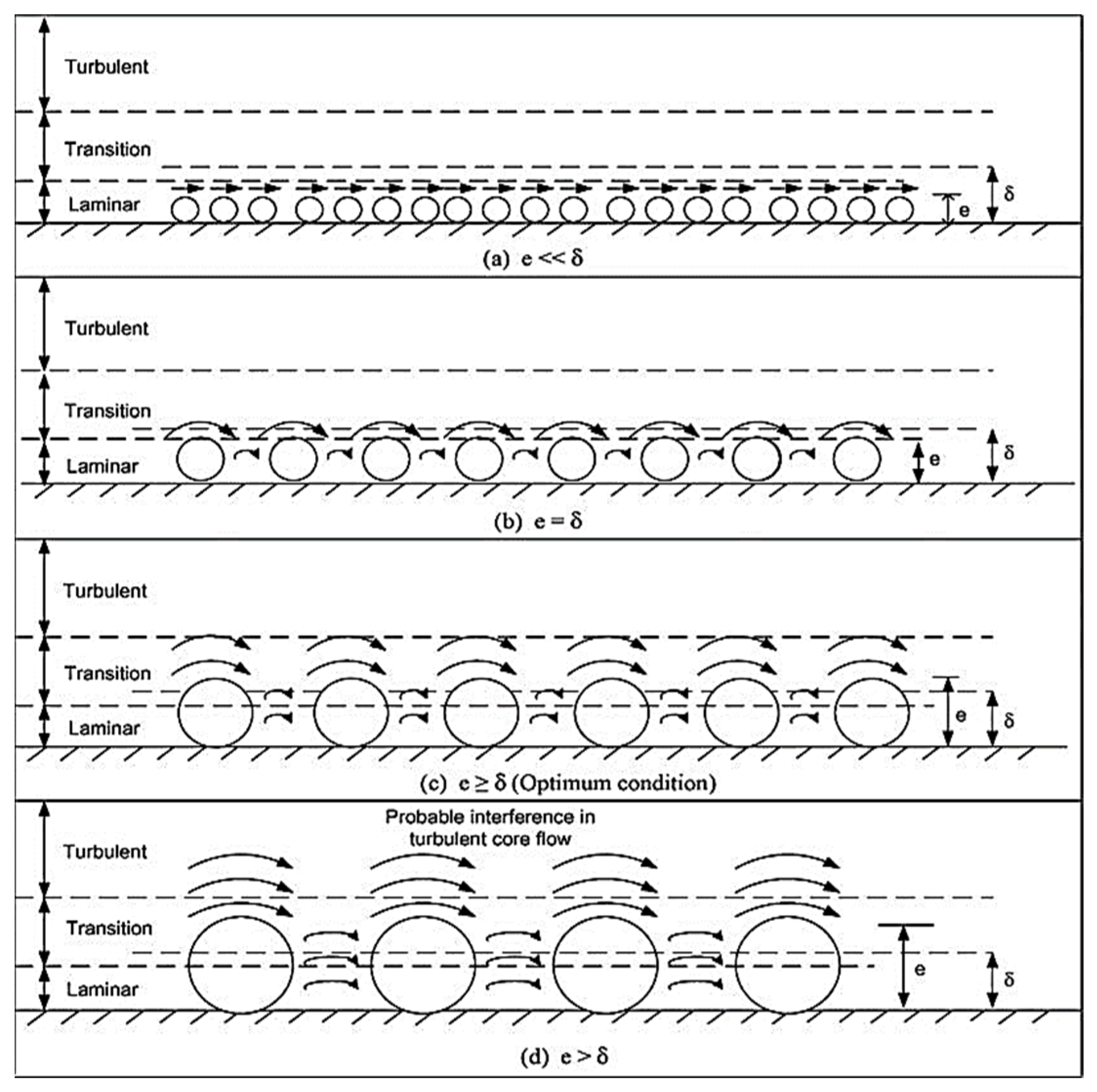
11.1.2. Effect of Relative Roughness Height (e/D)
11.1.3. Effect of Duct Aspect Ratio (W/H)
11.1.4. Effect of Angle of Attack (α)
11.1.5. Effect of Relative Roughness Width (W/w)
11.1.6. Effect of Perforation (Open-Area Ratio (β))
11.1.7. Effect of Relative Gap Position (d/w or Gd/Lv or Gd/La)
11.1.8. Effect of Relative Gap Width (g/e)
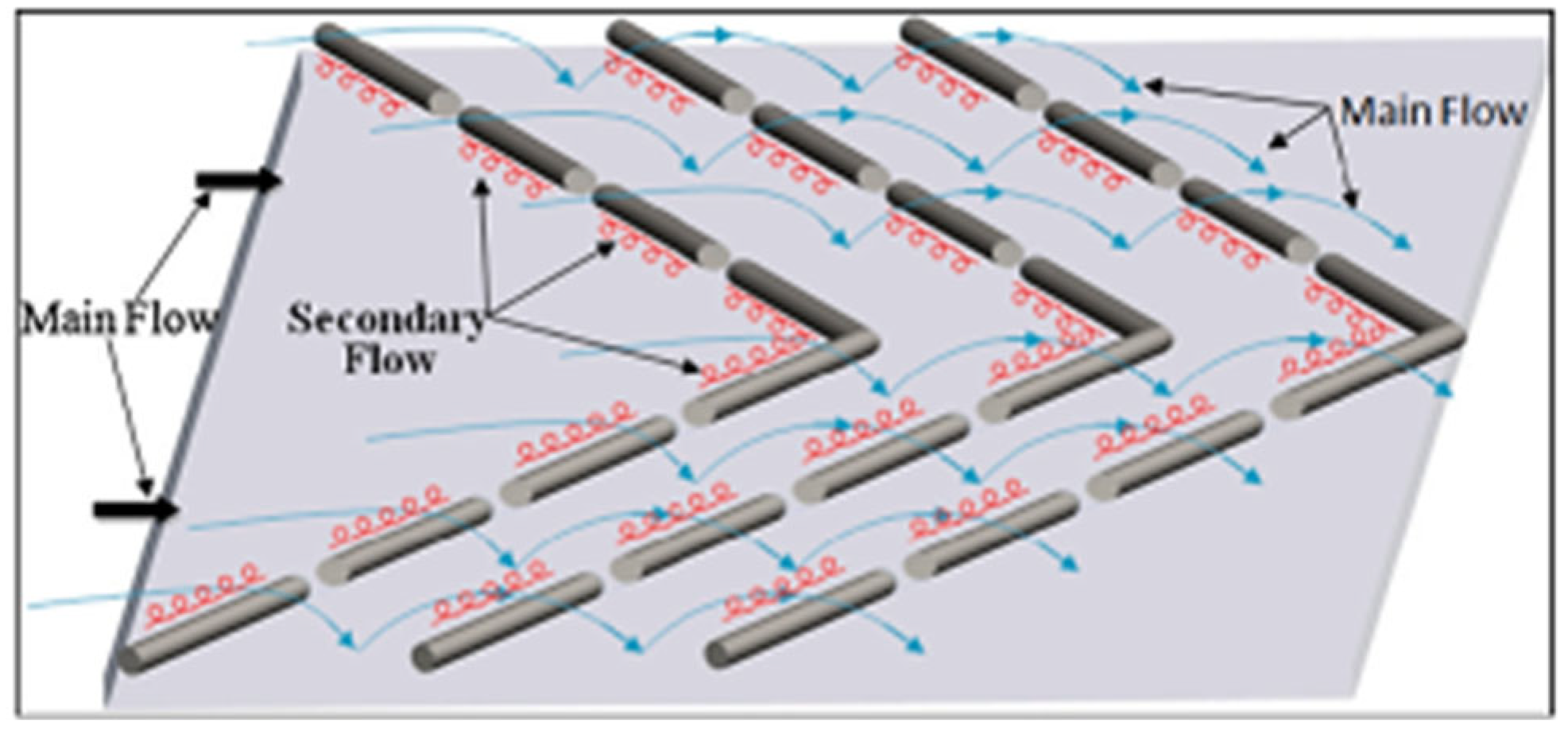
11.1.9. Effect of Staggering Parameters
11.1.10. Effect of Rib Cross-Section
11.1.11. Effect of SAH Slop (β)
11.2. Effect of Environmental Parameters on SAH Channel
11.2.1. Solar Insolation (I)
11.2.2. Temperatures of the Surrounding Air (Ta), Sky (Tsky), and Sun (Tsun)
11.2.3. Air Velocity (Va), Heat-Loss Coefficients (UL), and Heat-Transfer Coefficients (hw)
12. Thermal Performance of Artificially Roughened SAH
13. Thermo-Hydraulic Performance of Artificially Roughened SAH
- ηth is the thermal-conversion efficiency of the power plant;
- ηtr is the electrical-transmission efficiency;
- ηF is the fan efficiency;
- ηm is the electric-motor efficiency.
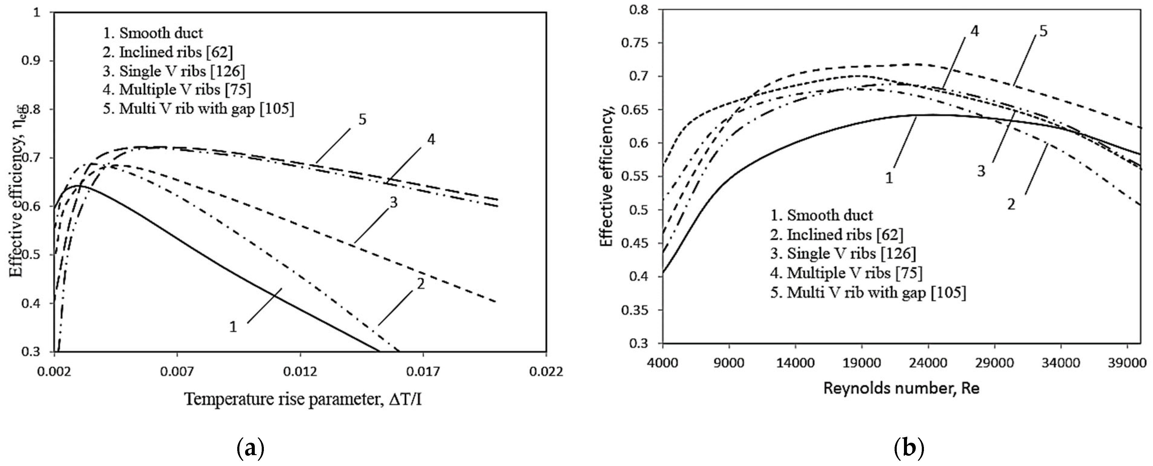
14. Comparison of Thermal Efficiency and Effective Efficiency for Various Roughness Shapes
15. Major Observations and Research Gaps Identified
- The multi-V-shaped rib is one of the best roughness geometries among all the studies. Most geometry parameters are optimized for continuous, gap, and staggered multi-V-rib roughness. However, very few works have been conducted to optimize parameters of perforated rib roughness, which perform far better than others.
- Because of a significant increase in the contact area, the thermal performance of DPSAH improved significantly, but a considerable gain in pumping power also occurred. The overall efficiency of DPSAH was observed to be better than SPSAH in all aspects.
- With DPSAH, most of the studies paid attention to packed bed materials and extended surfaces like fins or corrugated structures to improve the THP of SAH; only a few works of literature were available to determine the THP of the optimum roughness parameters with artificial roughness in the case of DPSAH.
- Because of significant increases in surface area and unidirectional airflow, DPPFSAH has high heat-transfer efficiency while creating minimum drag forces and reducing pumping power [218].
- Perforation in rib and baffle roughness provided in various rib designs significantly increases THPP compared to continuous rib configurations under similar operating conditions. During detachment and reattachment, the secondary stream’s mass-flow rate is accelerated through perforations, causing further turbulence [149].
- There was very little research available on the effect evaluation of perforation, especially in terms of variation in open-area ratio (β) on THP of SAH, and only few attempts have been made to optimize the open-area ratio (β) and its impact on a perforated multi-V-rib roughness in SPSAH and DPPFSAH [18].
Author Contributions
Funding
Institutional Review Board Statement
Informed Consent Statement
Data Availability Statement
Conflicts of Interest
Nomenclature
| Details of Symbols | Greek Symbols | ||
| A | Area, (m2) | Δ | Drop/gradient |
| Cd | Coefficient of discharge | δ | Partial |
| P | Mean static pressure (N/m2) | η | Efficiency |
| H | Height (m) | ϵ | Emissivity |
| h | Heat-transfer coefficient (W/m2 °C) | ʋ | Kinematic viscosity (m2/s) |
| I | Irradiance (W/m2) | α | Absorptivity |
| k | Thermal conductivity (W/m°C) | ρ | Air density (kg/m3) |
| t | Thickness (m) | α | Angle of attack (o) |
| Air mass-flow rate (kg/s) | β | Collector slope (o), open-area ratio | |
| P | Pitch distance (m) | μ | Dynamic viscosity (N.s/m2) |
| Q | Thermal energy transferred (J) | ψ | Circularity |
| q | Average heat generation (W/m3) | ν | Kinematic viscosity (m2/s) |
| T | Mean temperature (°C) | τ | Transmissivity |
| W | Width of channel (m) | Abbreviations | |
| w | Width of one set of ribs (m) | SP | Single pass |
| V | Velocity of working fluid (m/sec) | DP | Double pass |
| Dh | Hydraulic diameter (m) | THPP | Thermohydraulic performance parameter |
| SAH | Solar air heater | ||
| Subscripts | |||
| A | Ambient, air | m | Mean |
| abs | Absorber | u | Useful |
| Amb | Ambient | th | Thermal |
| d | Duct/channel, diameter | eff | Effective |
| g | Glass cover | ex. | Exergetic |
| h | Height, hole | Ins | Insulation |
References
- Sukhatme, S.P.; Nayak, J.K. Solar energy in western Rajasthan. Curr. Sci. 1997, 72, 62–68. Available online: http://www.jstor.org/stable/24098631 (accessed on 5 July 2022).
- Singh, V.P.; Jain, S.; Kumar, A. Establishment of correlations for the Thermo-Hydraulic parameters due to perforation in a multi-V rib roughened single pass solar air heater. Exp. Heat Transf. 2022, 1–20. [Google Scholar] [CrossRef]
- Duffie, J.A.; Kalogirou, S.A.; Duffie, S.A.; Kalogirou, J.A. Solar Economic Analysis. In Solar Energy Engineering; Elsevier: Amsterdam, The Netherlands, 2014. [Google Scholar]
- Murthy, S.G. Chapter Ten—Solar Energy in India; Elsevier Inc.: Amsterdam, The Netherlands, 2022. [Google Scholar]
- Duffie, J.A.; Beckman, W.A. Solar Engineering of Thermal Processes, 4th ed.; John Wiley and Sons: Hoboken, NJ, USA, 2013. [Google Scholar]
- Sakthivadivel, D.; Balaji, K.; Dsilva Winfred Rufuss, D.; Iniyan, S.; Suganthi, L. Chapter 1—Solar energy technologies: Principles and applications. In Renewable-Energy-Driven Future; Ren, J., Ed.; Academic Press: Cambridge, MA, USA, 2021; pp. 3–42. ISBN 978-0-12-820539-6. [Google Scholar]
- Sareen, S.; Kale, S.S. Energy Research & Social Science Solar ‘power’: Socio-political dynamics of infrastructural development in two Western Indian states. Energy Res. Soc. Sci. 2018, 41, 270–278. [Google Scholar] [CrossRef]
- Fuqiang, W.; Ziming, C.; Jianyu, T.; Yuan, Y.; Yong, S.; Linhua, L. Progress in concentrated solar power technology with parabolic trough collector system: A comprehensive review. Renew. Sustain. Energy Rev. 2017, 79, 1314–1328. [Google Scholar] [CrossRef]
- Saini, M.; Sharma, A.; Singh, V.P.; Jain, S.; Dwivedi, G. Solar Thermal Receivers—A Review. Lect. Notes Mech. Eng. 2022, II, 311–325. [Google Scholar] [CrossRef]
- Klein, S.A.; Beckman, W.A.; Duffie, J.A. A design procedure for solar air heating systems. Sol. Energy 1977, 19, 509–512. [Google Scholar] [CrossRef]
- Boer, K.W.; Duffie, J.A. Advances in Solar Energy: An Annual Review of Research and Development Volume 2; Springer: New York, NY, USA, 2012. [Google Scholar]
- Luo, X.; Ma, X.; Xu, Y.F.; Feng, Z.K.; Du, W.P.; Wang, R.; Li, M. Solar Water Heating System. In Handbook of Energy Systems in Green Buildings; Springer: Berlin/Heidelberg, Germany, 2018. [Google Scholar]
- Ravi Kumar, K.; Krishna Chaitanya, N.V.V.; Sendhil Kumar, N. Solar thermal energy technologies and its applications for process heating and power generation—A review. J. Clean. Prod. 2020, 282, 125296. [Google Scholar] [CrossRef]
- Kalogirou, S.A.; Florides, G.A. Solar Space Heating and Cooling Systems; Elsevier Inc.: Amsterdam, The Netherlands, 2016. [Google Scholar]
- Lupi, F.; Borri, C.; Harte, R.; Krätzig, W.B.; Niemann, H. J Facing technological challenges of Solar Updraft Power Plants. J. Sound Vib. 2015, 334, 57–84. [Google Scholar] [CrossRef]
- Alam, T.; Saini, R.P.; Saini, J.S. Heat and flow characteristics of air heater ducts provided with turbulators—A review. Renew. Sustain. Energy Rev. 2014, 31, 289–304. [Google Scholar] [CrossRef]
- Pandey, A.K.; Kumar, R.; Samykano, M. Chapter 1—Solar energy: Direct and indirect methods to harvest usable energy. In Dye-Sensitized Solar Cells; Pandey, A.K., Shahabuddin, S., Ahmad, M.S., Eds.; Academic Press: Cambridge, MA, USA, 2022; pp. 1–24. [Google Scholar]
- Singh, V.P.; Jain, S.; Gupta, J.M.L. Analysis of the effect of variation in open area ratio in perforated multi-V rib roughened single pass solar air heater—Part A. Energy Sources Part A Recover. Util. Environ. Eff. 2022, 30, 1–20. [Google Scholar] [CrossRef]
- Singh, V.P.; Jain, S.; Gupta, J. Analysis of the effect of perforation in multi-v rib artificial roughened single pass solar air heater—Part A. Exp. Heat Transf. 2021, 1–20. [Google Scholar] [CrossRef]
- Prasad, B.N.; Saini, J.S. Optimal thermohydraulic performance of artificially roughened solar air heaters. Sol. Energy 1991, 47, 91–96. [Google Scholar] [CrossRef]
- Varshney, L.; Saini, J.S.S. Heat transfer and friction factor correlations for rectangular solar air heater duct packed with wire mesh screen matrices. Sol. Energy 1998, 62, 255–262. [Google Scholar] [CrossRef]
- Meena, C.S.; Raj, B.P.; Saini, L.; Agarwal, N. Performance Optimization of Solar-Assisted Heat Pump System for Water Heating Applications. Energies 2021, 14, 3534. [Google Scholar] [CrossRef]
- Meena, C.S.; Meena, S.; Bajpai, V.K. Correlation between absorber plate thickness δ and collector efficiency factor F’ of solar flat-plate collector. Appl. Mech. Mater. 2014, 592–594, 2341–2344. [Google Scholar] [CrossRef]
- Deonarine, S.S.; Satcunanathan, D. A two-pass solar air heater. Sol. Energy 1973, 15, 41–49. [Google Scholar] [CrossRef]
- Aldabbagh, L.; Egelioglu, F.; Ilkan, M. Single and double pass solar air heaters with wire mesh as packing bed. Energy 2010, 35, 3783–3787. [Google Scholar] [CrossRef]
- Hu, J.; Zhang, G. Performance improvement of solar air collector based on airflow reorganization: A review Performance improvement of solar air collector based on airflow reorganization: A review. Appl. Therm. Eng. 2019, 155, 592–611. [Google Scholar] [CrossRef]
- Alam, T.; Kim, M.-H. Performance improvement of double-pass solar air heater—A state of art of review. Renew. Sustain. Energy Rev. 2017, 79, 779–793. [Google Scholar] [CrossRef]
- Ravi, R.K.; Saini, R.P. A review on different techniques used for performance enhancement of double pass solar air heaters. Renew. Sustain. Energy Rev. 2016, 56, 941–952. [Google Scholar] [CrossRef]
- Kumar, A.; Kumar, N.; Kumar, S.; Maithani, R. Exergetic efficiency analysis of impingement jets integrated with internal conical ring roughened solar heat collector. Exp. Heat Transf. 2021, 1–21. [Google Scholar] [CrossRef]
- Caliskan, S.; Dogan, A.; Sahin, U.R. Effect of new punched vortex generators in a rectangular channel on heat transfer using Taguchi method. Exp. Heat Transf. 2022, 35, 611–636. [Google Scholar] [CrossRef]
- El-Sebaii, A.A.; Aboul-Enein, S.; Ramadan, M.R.I.; Shalaby, S.M.; Moharram, B.M. Investigation of thermal performance of-double pass-flat and v-corrugated plate solar air heaters. Energy 2011, 36, 1076–1086. [Google Scholar] [CrossRef]
- Metwally, M.N.; Abouziyan, H.Z.; Elleathy, A.M. Performance of advanced corrugated-duct solar air collector compared with five conventional designs. Renew. Energy 1997, 10, 519–537. [Google Scholar] [CrossRef]
- Ozgen, F.; Esen, M.; Esen, H. Experimental investigation of thermal performance of a double-flow solar air heater having aluminium cans. Renew. Energy 2009, 34, 2391–2398. [Google Scholar] [CrossRef]
- Fudholi, A.; Sopian, K.; Ruslan, M.H. Thermal Efficiency of Double Pass Solar Collector with Longitudinal Fins Absorbers Thermal Efficiency of Double Pass Solar Collector with Longitudinal Fins Absorbers. Am. J. Appl. Sci. 2011, 8, 254–260. [Google Scholar] [CrossRef]
- Karim, M.A.; Hawlader, M.N.A. Performance investigation of flat plate, v-corrugated and finned air collectors. Energy 2006, 31, 452–470. [Google Scholar] [CrossRef]
- Kumar, A.; Akshayveer; Singh, A.P.; Singh, O.P. Efficient designs of double-pass curved solar air heaters. Renew. Energy 2020, 160, 1105–1118. [Google Scholar] [CrossRef]
- Ravi, R.K.; Saini, R.P. Experimental investigation on performance of a double pass artificial roughened solar air heater duct having roughness elements of the combination of discrete multi V shaped and staggered ribs. Energy 2016, 116, 507–516. [Google Scholar] [CrossRef]
- Kumar, A.; Kumar, A.; Dutt, N.; Singh, V.P.; Meena, C.S.; Prasad, A. Experimental Study of Process Parameter for Surface Roughness in WEDM. J. Mech. Eng. Prakash 2022, 1, 7–13. [Google Scholar] [CrossRef]
- Singh, S. Experimental and numerical investigations of a single and double pass porous serpentine wavy wiremesh packed bed solar air heater. Renew. Energy 2020, 145, 1361–1387. [Google Scholar] [CrossRef]
- Hassan, H.; Yousef, M.S.; Abo-elfadl, S. Energy, exergy, economic and environmental assessment of double pass V-corrugated-perforated finned solar air heater at different air mass ratios. Sustain. Energy Technol. Assess. 2020, 43, 100936. [Google Scholar] [CrossRef]
- Kumar, A.; Layek, A. Evaluation of the performance analysis of an improved solar air heater with Winglet shaped ribs. Exp. Heat Transf. 2020, 35, 239–257. [Google Scholar] [CrossRef]
- Ho, C.D.; Yeh, H.M.; Wang, R.C. Heat-transfer enhancement in double-pass flat-plate solar air heaters with recycle. Energy 2005, 30, 2796–2817. [Google Scholar] [CrossRef]
- Hassan, H.; Abo-Elfadl, S. Experimental study on the performance of double pass and two inlet ports solar air heater (SAH) at different configurations of the absorber plate. Renew. Energy 2018, 116, 728–740. [Google Scholar] [CrossRef]
- Ho, C.-D.; Tien, Y.-E.; Hsiao, C.-F. The influences of recycle effect on double-pass V-corrugated solar air heaters. Int. J. Green Energy 2017, 14, 1083–1092. [Google Scholar] [CrossRef]
- Nanjundappa, M. Optimum thermo-hydraulic performance of solar air heater provided with cubical roughness on the absorber surface. Exp. Heat Transf. 2020, 33, 374–387. [Google Scholar] [CrossRef]
- Abo-Elfadl, S.; Hassan, H.; El-Dosoky, M.F.F. Study of the performance of double pass solar air heater of a new designed absorber: An experimental work. Sol. Energy 2019, 198, 479–489. [Google Scholar] [CrossRef]
- Arunkumar, H.S.; Vasudeva Karanth, K.; Kumar, S. Review on the design modifications of a solar air heater for improvement in the thermal performance. Sustain. Energy Technol. Assess. 2020, 39, 100685. [Google Scholar] [CrossRef]
- Sharma, S.; Kumar, A.; Maithani, R. Influence of twisted tape with collective protruded rib parameters of thermal–hydraulic performance of Al2O3-H2O nanofluid flow in heat exchanger tube. Mater. Today Proc. 2022, 50, 1129–1133. [Google Scholar] [CrossRef]
- Forson, F.K.; Nazha, M.A.A.; Rajakaruna, H. Experimental and simulation studies on a single pass, double duct solar air heater. Energy Convers. Manag. 2003, 44, 1209–1227. [Google Scholar] [CrossRef]
- Abdullah, A.S.; Abou Al-sood, M.M.; Omara, Z.M.; Bek, M.A.; Kabeel, A.E. Performance evaluation of a new counter flow double pass solar air heater with turbulators. Sol. Energy 2018, 173, 398–406. [Google Scholar] [CrossRef]
- Esen, H.; Ozgen, F.; Esen, M.; Sengur, A. Artificial neural network and wavelet neural network approaches for modelling of a solar air heater. Expert Syst. Appl. 2009, 36, 11240–11248. [Google Scholar] [CrossRef]
- Pawar, R.S.; Takwale, M.G.; Bhide, V.G. Evaluation of the performance of the solar air heater. Energy Convers. Manag. 1994, 35, 699–708. [Google Scholar] [CrossRef]
- Hegazy, A.A. Thermohydraulic performance of air heating solar collectors with variable width, flat absorber plates. Energy Convers. Manag. 2000, 41, 1361–1378. [Google Scholar] [CrossRef]
- Garg, H.P.; Prakash, J.; Hrishikesan, D.S. Performance prediction of a solar timber kiln. Energy Convers. Manag. 1993, 34, 569–575. [Google Scholar] [CrossRef]
- Forson, F.K.; Nazha, M.A.A.; Rajakaruna, H. Modelling and experimental studies on a mixed-mode natural convection solar crop-dryer. Sol. Energy 2007, 81, 346–357. [Google Scholar] [CrossRef]
- Dhiman, P.; Thakur, N.S.; Kumar, A.; Singh, S. An analytical model to predict the thermal performance of a novel parallel flow packed bed solar air heater. Appl. Energy 2011, 88, 2157–2167. [Google Scholar] [CrossRef]
- Dhiman, P.; Thakur, N.S.; Chauhan, S.R. Thermal and thermohydraulic performance of counter and parallel flow packed bed solar air heaters. Renew. Energy 2012, 46, 259–268. [Google Scholar] [CrossRef]
- Yeh, H.; Ho, C.; Hou, J. The improvement of collector efficiency in solar air heaters by simultaneously air flow over and under the absorbing plate. Energy 1999, 24, 857–871. [Google Scholar] [CrossRef]
- González, S.M.; Larsen, S.F.; Hernández, A.; Lesino, G. Thermal evaluation and modeling of a double-pass solar collector for air heating. Proc. Energy Procedia 2014, 57, 2275–2284. [Google Scholar] [CrossRef]
- Singh, V.P.; Jain, S.; Gupta, J. Performance assessment of double-pass parallel flow solar air heater with perforated multi-V ribs roughness—Part B. Exp. Heat Transf. 2022, 1–18. [Google Scholar] [CrossRef]
- Verma, R.; Chandra, R.; Garg, H.P. Optimization of solar air heaters of different designs. Renew. Energy 1992, 2, 521–531. [Google Scholar] [CrossRef]
- Naphon, P. Effect of porous media on the performance of the double-pass flat plate solar air heater. Int. Commun. Heat Mass Transf. 2005, 32, 140–150. [Google Scholar] [CrossRef]
- Sopian, K.; Supranto; Daud, W.R.W.; Othman, M.Y.; Yatim, B. Thermal performance of the double-pass solar collector with and without porous media. Renew. Energy 1999, 18, 557–564. [Google Scholar] [CrossRef]
- Sopian, K.; Alghoul, M.A.; Alfegi, E.M.; Sulaiman, M.Y.; Musa, E.A. Evaluation of thermal efficiency of double-pass solar collector with porous—Nonporous media. Renew. Energy 2009, 34, 640–645. [Google Scholar] [CrossRef]
- Kumar, N.; Kumar, A.; Maithani, R.; Iqbal, Q.; Chen, C.; Hossain, F.; Small, H.; Shenton, A.K.; Hay-Gibson, N.V.; Mayr, P.; et al. Overview of V-RIB geometries in solar air heater and performance evaluation of a new V-RIB geometry. Renew. Energy 2020, 152, 77–90. [Google Scholar] [CrossRef]
- Naphon, P. On the performance and entropy generation of the double-pass solar air heater with longitudinal fins. Renew. Energy 2005, 30, 1345–1357. [Google Scholar] [CrossRef]
- Nowzari, R.; Aldabbagh, L.B.Y.; Egelioglu, F. Single and double pass solar air heaters with partially perforated cover and packed mesh. Energy 2014, 73, 694–702. [Google Scholar] [CrossRef]
- Karim, M.A.; Perez, E.; Amin, Z.M. Mathematical modelling of counter flow v-grove solar air collector. Renew. Energy 2014, 67, 192–201. [Google Scholar] [CrossRef]
- El-Sebaii, A.A.; Aboul-Enein, S.; Ramadan, M.R.I.; Shalaby, S.M.; Moharram, B.M. Thermal performance investigation of double pass-finned plate solar air heater. Appl. Energy 2011, 88, 1727–1739. [Google Scholar] [CrossRef]
- Wijeysundera, N.E.; Ah, L.L.; Tjioe, L.E. Thermal performance study of two-pass solar air heaters. Sol. Energy 1982, 28, 363–370. [Google Scholar] [CrossRef]
- Jin, D.; Zuo, J.; Quan, S.; Xu, S.; Gao, H. Thermohydraulic performance of solar air heater with staggered multiple V-shaped ribs on the absorber plate. Energy 2017, 127, 68–77. [Google Scholar] [CrossRef]
- ASHARE. Method of Testing to Determine the Thermal Performance of Solar Collectors. (ASHRAE Standard). 1985. Available online: https://www.osti.gov/servlets/purl/575023. (accessed on 5 July 2022).
- Hottel, H.; Woertz, B. Performance of flat-plate solar-heat collectors. Trans. ASME 1942, 64, 324–355. [Google Scholar]
- Bliss, R.W. The derivations of several “Plate-efficiency factors” useful in the design of flat-plate solar heat collectors. Sol. Energy 1959, 3, 55–64. [Google Scholar] [CrossRef]
- Bondi, P.; Clcala, L.; Farina, G. Performance of black-painted solar air heaters of conventional design. Sol. Energy 1988, 41, 101–107. [Google Scholar] [CrossRef]
- Kays, W.M.; Crawford, M.E. Convective Heat and Mass Transfer. In McGraw Hill Series in Mechanical Engineering; McGraw-Hill: New York, NY, USA, 1993; Volume 3. [Google Scholar]
- Majumdar, A. Handbook of Heat Transfer; Rohsenow, W.M., Hartnett, J.R., Cho, Y.I., Eds.; McGraw-Hill: New York, NY, USA, 1998. [Google Scholar]
- Niles, P.W.; Carnegie, E.J.; Pohl, J.G.; Cherne, J.M.; Resources, N.; Obispo, S.L.; Division, E.; Beach, R. Design and performance of an air collector. Transition 1978, 20, 19–23. [Google Scholar]
- Klein, S.A.; Duffie, J.A.; Beckman, W.A. Transient considerations of flat-plate solar collectors. J. Eng. Gas Turbines Power 1974, 96, 109–113. [Google Scholar] [CrossRef]
- Hill, J.E.; Kelly, G.E.; Geist, J.C.; Kusuda, T. Development of Proposed Standards for Testing Solar Collectors and Thermal Storage Devices. NBS Technical Note 899; U.S. Government Printing Office: Washington, DC, USA, 1981; pp. 1–265.
- Hill, J.E.; Jenkins, J.P.; Jones, D.E. Testing of Solar Collectors According To Ashrae Standard 93–77. ASHRAE Trans. 1978, 84, 107–125. [Google Scholar]
- Reddy, T.A.; Gupta, C.L. Generating application design data for solar air heating systems. Sol. Energy 1980, 25, 527–530. [Google Scholar] [CrossRef]
- Kumar, A.; Saini, R.P.P.; Saini, J.S.S. A review of thermohydraulic performance of artificially roughened solar air heaters. Renew. Sustain. Energy Rev. 2014, 37, 100–122. [Google Scholar] [CrossRef]
- Kumar, B.; Kumar, M.; Patil, A.K.; Jain, S. Effect of V cut in perforated twisted tape insert on heat transfer and fluid flow behavior of tube flow: An experimental study. Exp. Heat Transf. 2019, 32, 524–544. [Google Scholar] [CrossRef]
- Kumar, B.; Patil, A.K.; Jain, S.; Kumar, M. Study of Entropy Generation in Heat Exchanger Tube with Multiple v Cuts in Perforated Twisted Tape Insert. J. Heat Transf. 2019, 141, 081801. [Google Scholar] [CrossRef]
- Pandey, R.; Kumar, M.; Saini, J.S. Experimental study of parametric influence on heat transfer and friction in a rectangular duct having V-down baffle blocks with staggered racetrack-shaped openings. Exp. Heat Transf. 2021, 345, 818–847. [Google Scholar] [CrossRef]
- Patnaik, A.; Saini, R.P.P.; Singal, S.K.K. Siddhartha Performance prediction of solar air heater having roughened duct provided with transverse and inclined ribs as artificial roughness. Renew. Energy 2009, 34, 2914–2922. [Google Scholar] [CrossRef]
- Saini, R.P.; Singal, S.K. A review on roughness geometry used in solar air heaters. Sol. Energy 2007, 81, 1340–1350. [Google Scholar] [CrossRef]
- Sharma, A.; Goel, V.; Bharadwaj, G. Heat transfer and friction characteristics of double pass solar air heater having V-shaped roughness on the absorber plate Heat transfer and friction characteristics of double pass solar air heater having V-shaped roughness on the absorber plate. J. Renew. Sustain. Energy 2013, 5, 023109. [Google Scholar] [CrossRef]
- Rana, J.; Silori, A.; Maithani, R.; Chamoli, S. Computational fluid dynamics analysis of a V-rib with gap roughened solar air heater. Therm. Sci. 2018, 22, 963–972. [Google Scholar] [CrossRef]
- Ghritlahre, H.K.; Prasad, R.K. Prediction of heat transfer of two different types of roughened solar air heater using Artificial Neural Network technique. Therm. Sci. Eng. Prog. 2018, 8, 145–153. [Google Scholar] [CrossRef]
- Fan, W.; Kokogiannakis, G.; Ma, Z. Optimisation of life cycle performance of a double-pass photovoltaic thermal-solar air heater with heat pipes. Renew. Energy 2019, 138, 90–105. [Google Scholar] [CrossRef]
- Kumar, A. Analysis of heat transfer and fluid flow in different shaped roughness elements on the absorber plate solar air heater duct. Proc. Energy Procedia 2014, 57, 2102–2111. [Google Scholar] [CrossRef]
- Bisht, V.S.; Patil, A.K.; Gupta, A. Compact solar air heater: A review. Lect. Notes Mech. Eng. 2019, 1, 273–281. [Google Scholar] [CrossRef]
- Velmurugan, P.; Kalaivanan, R. Energy and exergy analysis of multi-pass flat plate solar air heater-an analytical approach. Int. J. Green Energy 2015, 12, 810–820. [Google Scholar] [CrossRef]
- Ghritlahre, H.K.; Verma, M. Accurate prediction of exergetic efficiency of solar air heaters using various predicting methods. J. Clean. Prod. 2020, 288, 125115. [Google Scholar] [CrossRef]
- Jin, D.; Zhang, M.; Wang, P.; Xu, S. Numerical investigation of heat transfer and fluid flow in a solar air heater duct with multi V-shaped ribs on the absorber plate. Energy 2015, 89, 178–190. [Google Scholar] [CrossRef]
- Deo, N.S.N.S.; Chander, S.; Saini, J.S. Performance analysis of solar air heater duct roughened with multigap V-down ribs combined with staggered ribs. Renew. Energy 2016, 91, 484–500. [Google Scholar] [CrossRef]
- Colakoglu, M.; Durmayaz, A. Multiobjective Optimization of a Novel Solar Tower-Based Gas Turbine-Driven Multi-Generation Plant with Energy, Exergy, Economic, and Environmental Impact Analysis. J. Energy Resour. Technol. 2022, 144, 051302. [Google Scholar] [CrossRef]
- Saravanan, A.; Murugan, M.; Reddy, M.S.; Ranjit, P.S.; Elumalai, P.V.; Kumar, P.; Sree, S.R. Thermo-hydraulic performance of a solar air heater with staggered C-shape finned absorber plate. Int. J. Therm. Sci. 2021, 168, 107068. [Google Scholar] [CrossRef]
- Thakur, D.S.; Khan, M.K.; Pathak, M. Solar air heater with hyperbolic ribs: 3D simulation with experimental validation. Renew. Energy 2017, 113, 357–368. [Google Scholar] [CrossRef]
- Kumar, A.; Kim, M.H. Heat transfer and fluid flow characteristics in air duct with various V-pattern rib roughness on the heated plate: A comparative study. Energy 2016, 103, 75–85. [Google Scholar] [CrossRef]
- Lanjewar, A.; Bhagoria, J.L.L.; Sarviya, R.M. Heat transfer and friction in solar air heater duct with W-shaped rib roughness on absorber plate. Energy 2011, 36, 4531–4541. [Google Scholar] [CrossRef]
- Kumar, R.; Goel, V.; Singh, P.; Saxena, A.; Kashyap, A.S.; Rai, A. Performance evaluation and optimization of solar assisted air heater with discrete multiple arc shaped ribs. J. Energy Storage 2019, 26, 100978. [Google Scholar] [CrossRef]
- Rajaseenivasan, T.; Srinivasan, S.; Srithar, K. Comprehensive study on solar air heater with circular and V-type turbulators attached on absorber plate. Energy 2015, 88, 863–873. [Google Scholar] [CrossRef]
- Tanda, G. Performance of solar air heater ducts with different types of ribs on the absorber plate. Energy 2011, 36, 6651–6660. [Google Scholar] [CrossRef]
- Al-Shamani, A.N.; Sopian, K.; Mohammed, H.A.; Mat, S.; Ruslan, M.H.; Abed, A.M. Enhancement heat transfer characteristics in the channel with Trapezoidal rib-groove using nanofluids. Case Stud. Therm. Eng. 2015, 5, 48–58. [Google Scholar] [CrossRef]
- Salih, S.M.; Jalil, J.M.; Najim, S.E. Double-Pass Solar air Heater (DP-SAH) utilizing Latent Thermal Energy Storage (LTES). IOP Conf. Ser. Mater. Sci. Eng. 2019, 518, 032038. [Google Scholar] [CrossRef]
- Bhowmik, H.; Amin, R. Efficiency improvement of flat plate solar collector using reflector. Energy Rep. 2017, 3, 119–123. [Google Scholar] [CrossRef]
- Samdarshi, S.K.; Mullick, S.C. Analysis of the top heat loss factor of flat plate solar collectors with single and double glazing. Int. J. Energy Res. 1990, 14, 975–990. [Google Scholar] [CrossRef]
- Souka, A.F. Double exposure flat-plate collector. Sol. Energy 1965, 9, 117–118. [Google Scholar] [CrossRef]
- Suri, R.K.; Saini, J.S. Performance Prediction of Single- and Double-Exposure Solar-air Heaters. Sol. Energy 1969, 12, 525–530. [Google Scholar] [CrossRef]
- Ward, D.A.N.S.; Weiss, T.A.; Lof, G.O.G. Preliminary performance of CSU Solar House I heating and cooling system. Sol. Energy 1976, 18, 541–548. [Google Scholar] [CrossRef]
- Ward, D.S.; Löf, G.O.G.; Smith, C.C.; Shaw, L.L. Design of a solar heating and cooling system for CSU solar house II. Sol. Energy 1977, 19, 79–85. [Google Scholar] [CrossRef]
- Selçuk, K. Thermal and economic analysis of the overlapped-glass plate solar-air heater. Sol. Energy 1971, 13, 165–191. [Google Scholar] [CrossRef]
- Malhotra, A.; Garg, H.P.; Rani, U. Minimizing convective heat losses in flat plate solar collectors. Sol. Energy 1980, 25, 521–526. [Google Scholar] [CrossRef]
- Abuşka, M.; Şevik, S.; Kayapunar, A. Experimental analysis of solar air collector with PCM-honeycomb combination under the natural convection. Sol. Energy Mater. Sol. Cells 2019, 195, 299–308. [Google Scholar] [CrossRef]
- Buchberg, H.; Edwards, D.K.; Mackenzie, J.D.; Science, A.; Angeles, L. Transparent Glass Honeycomb Structures for Energy Loss Control; Technical Report UCLA-ENG-8; School of Engineering and Applied Science, California University: Los Angeles, CA, USA, 1980. [Google Scholar]
- Buchberg, H.; Edwards, D.K. Design considerations for solar collectors with cylindrical glass honeycombs. Sol. Energy 1976, 18, 193–203. [Google Scholar] [CrossRef]
- Caouris, Y.; Rigopoulos, R.; Tripanagnostopoulos, J.; Yianoulis, P. A novel solar collector. Sol. Energy 1978, 21, 157–160. [Google Scholar] [CrossRef]
- Mohamad, A.A. High efficiency solar air heater. Sol. Energy 1997, 60, 71–76. [Google Scholar] [CrossRef]
- Persad, P.; Satcunanathan, S. The Thermal Performance of the Air Heater. J. Sol. Energy Eng. ASME 1983, 105, 254–258. [Google Scholar] [CrossRef]
- Sodha, M.S.; Bansal, N.K.; Singh, D. Analysis of a non-porous double-flow solar air heater. Appl. Energy 1982, 12, 251–258. [Google Scholar] [CrossRef]
- Choudhury, C.; Chauhan, P.M.; Garg, H.P. Performance and cost analysis of two-pass solar air heaters. Heat Recover. Syst. CHP 1995, 15, 755–773. [Google Scholar] [CrossRef]
- Klein, S.A. Calculation of flat-plate collector loss coefficients. Sol. Energy 1975, 17, 79–80. [Google Scholar] [CrossRef]
- Agarwal, V.K.; Larson, D.C. Calculation of the top loss coefficient of a flat-plate collector. Sol. Energy 1981, 27, 69–71. [Google Scholar] [CrossRef]
- Nayak, R.K.; Singh, S.N. Effect of geometrical aspects on the performance of jet plate solar air heater. Sol. Energy 2016, 137, 434–440. [Google Scholar] [CrossRef]
- Soni, A.; Singh, S.N. Experimental analysis of geometrical parameters on the performance of an inline jet plate solar air heater. Sol. Energy 2017, 148, 149–156. [Google Scholar] [CrossRef]
- Matheswaran, M.M.; Arjunan, T.V.; Muthusamy, S.; Natrayan, L.; Panchal, H.; Subramaniam, S.; Khedkar, N.K.; El-Shafay, A.S.; Sonawane, C. A case study on thermo-hydraulic performance of jet plate solar air heater using response surface methodology. Case Stud. Therm. Eng. 2022, 34, 101983. [Google Scholar] [CrossRef]
- Choudhury, C.; Garg, H.P.; Khas, H. Evaluation of a jet plate solar air heater. Sol. Energy 1991, 46, 199–209. [Google Scholar] [CrossRef]
- Behura, A.K.; Kumar, A.; Todkari, V.C.; Dwivedi, G.; Gupta, H.K. Analysis of thermal efficiency of solar flat plate collector using twisted tape. In Advances in Air Conditioning and Refrigeration; Lecture Notes in Mechanical Engineering; Springer: Berlin/Heidelberg, Germany, 2021; pp. 89–97. [Google Scholar] [CrossRef]
- Yeh, H.; Ho, C.; Hou, J. Collector efficiency of double-flow solar air heaters with fins attached. Energy 2002, 27, 715–727. [Google Scholar] [CrossRef]
- Ho, C.-D.; Yeh, H.-M.; Chen, T.-C. Collector efficiency of upward-type double-pass solar air heaters with fins attached. Int. Commun. Heat Mass Transf. 2011, 38, 49–56. [Google Scholar] [CrossRef]
- Joudi, K.A.; Mohammed, A.I. Experimental performance of a solar air heater with a “V” corrugated absorber. Energy Convers. Manag. 1986, 26, 193–200. [Google Scholar] [CrossRef]
- HONG, S.W.; BERGLES, A.E. Augmentation of Laminar Flow Heat Transfer in Tubes By Means of Twisted-Tape Inserts. J. Heat Transf. 1976, 98, 251–256. [Google Scholar] [CrossRef]
- Wen, M.Y.; Jang, K.J.; Yang, C.C. Augmented heat transfer and pressure drop of strip-type inserts in the small tubes. Heat Mass Transf. Stoffuebertragung 2003, 40, 133–141. [Google Scholar] [CrossRef]
- Chiou, J.P.; El-Wakil, M.M.; Duffie, J.A. A slit and expanded aluminum foil matrix solar collector. Sol. Energy 1965, 9, 73–80. [Google Scholar] [CrossRef]
- Toǧrul, I.T.; Pehlivan, D. Effect of packing in the airflow passage on the performance of a solar air-heater with conical concentrator. Appl. Therm. Eng. 2005, 25, 1349–1362. [Google Scholar] [CrossRef]
- Prasad, S.B.; Saini, J.S.; Singh, K.M. Investigation of heat transfer and friction characteristics of packed bed solar air heater using wire mesh as packing material. Sol. Energy 2009, 83, 773–783. [Google Scholar] [CrossRef]
- Kumar, A.; Kim, M.-H. Solar air-heating system with packed-bed energy-storage systems. Renew. Sustain. Energy Rev. 2017, 72, 215–227. [Google Scholar] [CrossRef]
- Tiwari, P.; Kumar, A.; Sarviya, R.M. Thermal performance of packed bed solar air heater. In Proceedings of the 2013 International Conference on Energy Efficient Technologies for Sustainability, ICEETS 2013, Nagercoil, India, 10–12 April 2013; pp. 438–442. [Google Scholar]
- Zheng, W.; Zhang, H.; You, S.; Fu, Y.; Zheng, X. Thermal performance analysis of a metal corrugated packing solar air collector in cold regions. Appl. Energy 2017, 203, 938–947. [Google Scholar] [CrossRef]
- Ramani, B.M.; Gupta, A.; Kumar, R. Performance of a double pass solar air collector. Sol. Energy 2010, 84, 1929–1937. [Google Scholar] [CrossRef]
- Sopian, K.; Supranto; Othman, M.Y.; Daud, W.R.; Yatim, B. Double-Pass Solar Collectors with Porous Media Suitable for Higher-Temperature Solar-Assisted Drying Systems. J. Energy Eng. 2007, 133, 13–18. [Google Scholar] [CrossRef]
- Roy, A.; Hoque, M.E. Performance analysis of double pass solar air heater with packed bed porous media in Rajshahi. Proc. AIP Conf. Proc. 2017, 1851, 020010. [Google Scholar]
- Verma, P.; Varshney, L. Parametric investigation on thermo-hydraulic performance of wire screen matrix packed solar air heater. Sustain. Energy Technol. Assess. 2015, 10, 40–52. [Google Scholar] [CrossRef]
- Hans, V.S.; Saini, R.P.; Saini, J.S. Heat transfer and friction factor correlations for a solar air heater duct roughened artificially with multiple v-ribs. Sol. Energy 2010, 84, 898–911. [Google Scholar] [CrossRef]
- Joule, J.P., VIII. On the surface-condensation of steam. Phil. Trans. R. Soc. 1861, 151, 133–160. [Google Scholar] [CrossRef]
- Alam, T.; Kim, M.-H. A critical review on artificial roughness provided in rectangular solar air heater duct. Renew. Sustain. Energy Rev. 2017, 69, 387–400. [Google Scholar] [CrossRef]
- Verma, D.; Fortunati, E.; Jain, S.; Zhang, X. Biomass, Biopolymer-Based Materials, and Bioenergy: Construction, Biomedical, and Other Industrial Applications; Elsevier Science: Amsterdam, The Netherlands, 2019; ISBN 9780081024270. [Google Scholar]
- Jain, S.; Sharma, M.P. Oxidation, Thermal, and Storage Stability Studies of Jatropha Curcas Biodiesel. ISRN Renew. Energy 2012, 2012, 861293. [Google Scholar] [CrossRef]
- Kumar, B.; Patil, A.K.; Jain, S.; Kumar, M. Effects of Double V Cuts in Perforated Twisted Tape Insert: An Experimental Study. Heat Transf. Eng. 2019, 41, 17. [Google Scholar] [CrossRef]
- Ghritlahre, H.K.; Sahu, P.K.; Chand, S. Thermal performance and heat transfer analysis of arc shaped roughened solar air heater—An experimental study. Sol. Energy 2020, 199, 173–182. [Google Scholar] [CrossRef]
- Jain, S.; Sharma, M.P. Engine performance and emission analysis using oxidatively stabilized Jatropha curcas biodiesel. Fuel 2013, 106, 152–156. [Google Scholar] [CrossRef]
- Prasad, K.; Mullick, S.C. Heat transfer characteristics of a solar air heater used for drying purposes. Appl. Energy 1983, 13, 83–93. [Google Scholar] [CrossRef]
- Webb, R.L.; Eckert, E.R.G.; Goldstein, R.J. Heat transfer and friction in tubes with repeated-rib roughness. Int. J. Heat Mass Transf. 1971, 14, 601–617. [Google Scholar] [CrossRef]
- Kreith, F.; Boehm, R.F.; Raithby, G.D.; Hollands, K.G.T.; Suryanarayana, N.V.; Modest, M.F.; Carey, V.P.; Chen, J.C.; Lior, N.; Shah, R.K.; et al. Heat and mass transfer. In CRC Handbook of Mechanical Engineering, 2nd ed.; CRC: Boca Raton, FL, USA, 1999; Volume 4, pp. 341–357. [Google Scholar] [CrossRef]
- Webb, R.L.; Eckert, E.R.G. Application of rough surfaces to heat exchanger. Int. J. Heat Mass Transf. 1972, 15, 1647–1658. [Google Scholar] [CrossRef]
- Prasad, B.N.; Saini, J.S. Effect of artificial roughness on heat transfer and friction factor in a solar air heater. Sol. Energy 1988, 41, 555–560. [Google Scholar] [CrossRef]
- Ebrahim Momin, A.-M.; Saini, J.S.; Solanki, S.C. Heat transfer and friction in solar air heater duct with V-shaped rib roughness on absorber plate. Int. J. Heat Mass Transf. 2002, 45, 3383–3396. [Google Scholar] [CrossRef]
- Maithani, R.; Saini, J.S. Performance evaluation of solar air heater having V-ribs with symmetrical gaps in a rectangular duct of solar air heater. Int. J. Ambient. Energy 2017, 38, 400–410. [Google Scholar] [CrossRef]
- Kumar, A.; Saini, R.P.P.; Saini, J.S.S. Development of correlations for Nusselt number and friction factor for solar air heater with roughened duct having multi v-shaped with gap rib as arti fi cial roughness. Renew. Energy 2013, 58, 151–163. [Google Scholar] [CrossRef]
- Lanjewar, A.M.; Bhagoria, J.L.; Sarviya, R.M. Performance analysis of W-shaped rib roughened solar air heater. J. Renew. Sustain. Energy 2011, 3, 043110. [Google Scholar] [CrossRef]
- Singh Patel, S.; Lanjewar, A. Experimental and numerical investigation of solar air heater with novel V-rib geometry. J. Energy Storage 2019, 21, 750–764. [Google Scholar] [CrossRef]
- Karwa, R.; Bairwa, R.D.; Jain, B.P.; Karwa, N. Experimental study of the effects of rib angle and discretization on heat transfer and friction in an asymmetrically heated rectangular duct. J. Enhanc. Heat Transf. 2005, 12, 343–355. [Google Scholar] [CrossRef]
- Singh, S. Thermal performance analysis of semicircular and triangular cross-sectioned duct solar air heaters under external recycle. J. Energy Storage 2018, 20, 316–336. [Google Scholar] [CrossRef]
- Patil, A.K.; Saini, J.S.; Kumar, K. Nusselt number and friction factor correlations for solar air heater duct with broken V-down ribs combined with staggered rib roughness. J. Renew. Sustain. Energy 2012, 4, 033122. [Google Scholar] [CrossRef]
- Wright, L.M.; Fu, W.L.; Han, J.C. Thermal performance of angled, V-shaped, and W-shaped rib turbulators in rotating rectangular cooling channels (AR=4:1). J. Turbomach. 2004, 126, 604–614. [Google Scholar] [CrossRef]
- Kumar, A.; Kumar, R.; Maithani, R.; Chauhan, R.; Sethi, M.; Kumari, A.; Kumar, S.; Kumar, S. Correlation development for Nusselt number and friction factor of a multiple type V-pattern dimpled obstacles solar air passage. Renew. Energy 2017, 109, 461–479. [Google Scholar] [CrossRef]
- Tamna, S.; Skullong, S.; Thianpong, C.; Promvonge, P. Heat transfer behaviors in a solar air heater channel with multiple V-baffle vortex generators. Sol. Energy 2014, 110, 720–735. [Google Scholar] [CrossRef]
- Misra, R.; Singh, J.; Kumar, S.; Faujdar, S.; Agrawal, M. Prediction of behavior of triangular solar air heater duct using V-down rib with multiple gaps and turbulence promoters as artificial roughness: A CFD analysis. Int. J. Heat Mass Transf. 2020, 162, 120376. [Google Scholar] [CrossRef]
- Kumar, A.; Layek, A. Nusselt number and friction characteristics of a solar air heater that has a winglet type vortex generator in the absorber surface. Exp. Therm. Fluid Sci. 2020, 119, 110204. [Google Scholar] [CrossRef]
- Kumar, R.; Kumar, A.; Chauhan, R.; Maithani, R. Comparative study of effect of various blockage arrangements on thermal hydraulic performance in a roughened air passage. Renew. Sustain. Energy Rev. 2018, 81, 447–463. [Google Scholar] [CrossRef]
- Singh, A.; Kumar, M.; Alam, T.; Saini, R.P.; Saini, J.S.; Patel, S.S.; Lanjewar, A.; Ghritlahre, H.K.; Prasad, R.K.; Bisht, V.S.; et al. Effect of circularity of perforation holes in V-shaped blockages on heat transfer and friction characteristics of rectangular solar air heater duct. Energy Convers. Manag. 2014, 86, 952–963. [Google Scholar] [CrossRef]
- Chamoli, S.; Thakur, N.S.S. Correlations for solar air heater duct with V-shaped perforated baffles as roughness elements on absorber plate. Int. J. Sustain. Energy 2013, 35, 37–41. [Google Scholar] [CrossRef]
- Skullong, S.; Promthaisong, P.; Promvonge, P.; Thianpong, C.; Pimsarn, M. Thermal performance in solar air heater with perforated-winglet-type vortex generator. Sol. Energy 2018, 170, 1101–1117. [Google Scholar] [CrossRef]
- Jain, S.K.; Misra, R.; Kumar, A.; Agrawal, G.D. Thermal performance investigation of a solar air heater having discrete V-shaped perforated baffles. Int. J. Ambient. Energy 2019, 43, 243–251. [Google Scholar] [CrossRef]
- Promvonge, P.; Khanoknaiyakarn, C.; Kwankaomeng, S.; Thianpong, C. Thermal behavior in solar air heater channel fitted with combined rib and delta-winglet. Int. Commun. Heat Mass Transf. 2011, 38, 749–756. [Google Scholar] [CrossRef]
- Skullong, S.; Promvonge, P.; Thianpong, C.; Pimsarn, M. Thermal performance in solar air heater channel with combined wavy-groove and perforated-delta wing vortex generators. Appl. Therm. Eng. 2016, 100, 611–620. [Google Scholar] [CrossRef]
- Karwa, R.; Maheshwari, B.K.K. Heat transfer and friction in an asymmetrically heated rectangular duct with half and fully perforated baffles at different pitches. Int. Commun. Heat Mass Transf. 2009, 36, 264–268. [Google Scholar] [CrossRef]
- Verma, S.K.K.; Prasad, B.N.N. Investigation for the optimal thermohydraulic performance of artificially roughened solar air heaters. Renew. Energy 2000, 20, 19–36. [Google Scholar] [CrossRef]
- Sahu, M.M.; Bhagoria, J.L. Augmentation of heat transfer coefficient by using 90 8 broken transverse ribs on absorber plate of solar air heater. Renew. Energy 2005, 30, 2057–2073. [Google Scholar] [CrossRef]
- Gupta, D.; Solanki, S.C.C.; Saini, J.S.S. Thermohydraueic performance of solar air heaters with roughened absorber plates. Sol. Energy 1997, 61, 33–42. [Google Scholar] [CrossRef]
- Pawar, C.B.; Aharwal, K.R.; Chaube, A. Heat transfer and fluid flow characteristics of rib-groove roughened solar air heater ducts. Indian J. Sci. Technol. 2009, 2, 50–54. [Google Scholar] [CrossRef]
- Varun; Saini, R.P.; Singal, S.K. Investigation of thermal performance of solar air heater having roughness elements as a combination of inclined and transverse ribs on the absorber plate. Renew. Energy 2008, 33, 1398–1405. [Google Scholar] [CrossRef]
- Gupta, D.; Solanki, S.C.; Saini, J.S. Heat and fluid flow in rectangular solar air heater ducts having transverse rib roughness on absorber plates. Sol. Energy 1993, 51, 31–37. [Google Scholar] [CrossRef]
- Rohit, A.K.; Lanjewar, A. Thermo-hydraulic performance evaluation using W-Discrete rib in solar air heater. Indian J. Sci. Technol. 2016, 9, 90–97. [Google Scholar] [CrossRef]
- Singh, S.; Chander, S.; Saini, J.S.S. Heat transfer and friction factor of discrete V-down rib roughened solar air heater ducts. J. Renew. Sustain. Energy 2011, 3, 013108. [Google Scholar] [CrossRef]
- Maithani, R.; Saini, J.S.S. Heat transfer and friction factor correlations for a solar air heater duct roughened artificially with V-ribs with symmetrical gaps. Exp. Therm. Fluid Sci. 2016, 70, 220–227. [Google Scholar] [CrossRef]
- Kwak, J.S.; Shin, S. Effect of hole shape on the heat transfer in a rectangular duct with perforated blockage walls. J. Mech. Sci. Technol. 2008, 22, 1945–1951. [Google Scholar] [CrossRef]
- Lewis, M.J. Optimising the thermohydraulic performance of rough surfaces. Int. J. Heat Mass Transf. 1975, 18, 1243–1248. [Google Scholar] [CrossRef]
- Mohanty, C.P.; Behura, A.K.; Singh, M.R.; Prasad, B.N.; Kumar, A.; Dwivedi, G.; Verma, P. Parametric performance optimization of three sides roughened solar air heater. Energy Sources Part A Recover. Util. Environ. Eff. 2020. [Google Scholar] [CrossRef]
- Ravi, R.K.; Saini, R.P. Nusselt number and friction factor correlations for forced convective type counter flow solar air heater having discrete multi V shaped and staggered rib roughness on both sides of the absorber plate. Appl. Therm. Eng. 2018, 129, 735–746. [Google Scholar] [CrossRef]
- Ravi, R.K.; Saini, R.P. Effect of roughness elements on thermal and thermohydraulic performance of double pass solar air heater duct having discrete multi V-shaped and staggered rib roughness on both sides of the absorber plate. Exp. Heat Transf. 2017, 6152, 47–67. [Google Scholar] [CrossRef]
- Chhaparwal, G.K.; Srivastava, A.; Dayal, R. Artificial repeated-rib roughness in a solar air heater—A review. Sol. Energy 2019, 194, 329–359. [Google Scholar] [CrossRef]
- Han, J.C.; Zhang, Y.M. High performance heat transfer ducts with parallel broken and V-shaped broken ribs. Int. J. Heat Mass Transf. 1992, 35, 513–523. [Google Scholar] [CrossRef]
- Karwa, R.; Sharma, A.; Karwa, N. A comparative study of different roughness geometries proposed for solar air heater ducts. Int. Rev. Mech. Eng. 2010, 4, 159–166. [Google Scholar]
- Ghritlahre, H.K.; Verma, M.; Parihar, J.S.; Mondloe, D.S.; Agrawal, S. A detailed review of various types of solar air heaters performance. Sol. Energy 2022, 237, 173–195. [Google Scholar] [CrossRef]
- Singh, S.; Chander, S.; Saini, J.S. Thermal and effective efficiency based analysis of discrete V-down rib-roughened solar air heaters. J. Renew. Sustain. Energy 2011, 3, 023107. [Google Scholar] [CrossRef]
- Vogiatzis, I.I.; Denizopoulou, A.C.; Ntinas, G.K.; Fragos, V.P. Simulation analysis of air flow and turbulence statistics in a rib grit roughened duct. Sci. World J. 2014, 2014, 791513. [Google Scholar] [CrossRef]
- Tariq, A.; Panigrahi, P.K.; Muralidhar, K. Flow and heat transfer in the wake of a surface-mounted rib with a slit. Exp. Fluids 2004, 37, 701–719. [Google Scholar] [CrossRef]
- Aharwal, K.R.; Gandhi, B.K.; Saini, J.S. Experimental investigation on heat-transfer enhancement due to a gap in an inclined continuous rib arrangement in a rectangular duct of solar air heater. Renew. Energy 2008, 33, 585–596. [Google Scholar] [CrossRef]
- Singh, S.N. Flow and heat transfer studies in a double—Pass counter flow Solar Air Heater. Int. J. Heat Technol. 2013, 31, 37–42. [Google Scholar] [CrossRef]
- Karwa, R. Experimental studies of augmented heat transfer and friction in asymmetrically heated rectabgular ducts with ribs on the heated wall in transverse, inclined, v-continous and v-discrete pattern. Int. Commun. Heat Mass Transf. 2003, 30, 241–250. [Google Scholar] [CrossRef]
- Gawande, V.B.; Dhoble, A.S.; Zodpe, D.B. Effect of roughness geometries on heat transfer enhancement in solar thermal systems—A review. Renew. Sustain. Energy Rev. 2014, 32, 347–378. [Google Scholar] [CrossRef]
- Karmare, S.V.; Tikekar, A.N. Experimental investigation of optimum thermohydraulic performance of solar air heaters with metal rib grits roughness. Sol. Energy 2009, 83, 6–13. [Google Scholar] [CrossRef]
- Kumar, A.; Saini, R.P.; Saini, J.S. Effect of roughness width ratio in discrete Multi v-shaped rib roughness on thermo-hydraulic performance of solar air heater. Heat Mass Transf. Stoffuebertragung 2014, 51, 209–220. [Google Scholar] [CrossRef]
- Cortés, A.; Piacentini, R. Improvement of the Efficiency of a Bare Solar Collector by Means of Turbulence Promoters. Appl. Energy 2000, 36, 253–261. [Google Scholar] [CrossRef]
- Gupta, M.K.K.; Kaushik, S.C.C. Performance evaluation of solar air heater for various artificial roughness geometries based on energy, effective and exergy efficiencies. Renew. Energy 2009, 34, 465–476. [Google Scholar] [CrossRef]
- Bahrehmand, D.; Ameri, M.; Gholampour, M. Energy and exergy analysis of different solar air collector systems with forced convection. Renew. Energy 2015, 83, 1119–1130. [Google Scholar] [CrossRef]
- Saravanakumar, P.T.; Somasundaram, D.; Matheswaran, M.M. Exergetic investigation and optimization of arc shaped rib roughened solar air heater integrated with fins and baffles. Appl. Therm. Eng. 2020, 175, 115316. [Google Scholar] [CrossRef]
- Abo-elfadl, S.; Yousef, M.S.; Hassan, H. Energy, exergy, and enviroeconomic assessment of double and single pass solar air heaters having a new design absorber. Process Saf. Environ. Prot. 2021, 149, 451–464. [Google Scholar] [CrossRef]
- Saravanakumar, P.T.; Somasundaram, D.; Matheswaran, M.M. Thermal and thermo-hydraulic analysis of arc shaped rib roughened solar air heater integrated with fins and baffles. Sol. Energy 2019, 180, 360–371. [Google Scholar] [CrossRef]
- Maithani, R.; Agarwal, R.; Kumar, A.; Sharma, S. Parametric optimization of impinging air jet on hemispherical protrusion of a solar thermal collector. Exp. Heat Transf. 2022, 1–22. [Google Scholar] [CrossRef]
- Ghritlahre, H.K.; Sahu, P.K. A comprehensive review on energy and exergy analysis of solar air heaters. Arch. Thermodyn. 2020, 41, 183–222. [Google Scholar] [CrossRef]
- Mittal, M.K.; Varun; Saini, R.P.; Singal, S.K. Effective efficiency of solar air heaters having different types of roughness elements on the absorber plate. Energy 2007, 32, 739–745. [Google Scholar] [CrossRef]
- Singh, V.P.; Jain, S.; Karn, A.; Kumar, A.; Dwivedi, G. Mathematical Modeling of Efficiency Evaluation of Double Pass Parallel Flow Solar Air Heater. Sustainability 2022, 14, 10535. [Google Scholar] [CrossRef]
- Hernández, A.L.; Quiñonez, J.E. Analytical models of thermal performance of solar air heaters of double-parallel flow and double-pass counter flow. Renew. Energy 2013, 55, 380–391. [Google Scholar] [CrossRef]


| S. No. | Researcher | Proposed-Roughness Shape of Rib | THPP | ||||||
|---|---|---|---|---|---|---|---|---|---|
| 1 | Varun et al. [18] | Multi-V (perforated) SPSAH | 8.20 | 6.20 | 5.15 | ||||
| 2 | Varun et al. [60] | Multi-V (perforated) DPPFSAH | 9.70 | 12.32 | 3.96 | ||||
| 3 | Prasad-Saini [159] | Transverse | 2.39 | 4.26 | -- | ||||
| 4 | Momin et al. [160] | V(Continuous) | 2.31 | 2.84 | 1.80 | ||||
| 5 | Saini et al. [161] | V(gap) | 3.61 | 3.68 | -- | ||||
| 6 | Saini et al. [162] | Multi-V(gap) | 6.33–6.75 | 6.13–6.36 | -- | ||||
| 7 | Hans et al. [147] | Multi-V(regular) | 6.01 | 5.01 | -- | ||||
| 8 | Bhagoria et al. [163] | V and W | 2.14–2.35 | 2.18–2.01 | 1.28–1.97 | ||||
| 9 | Patel and Lanjewar [164] | Multi-V(staggering) | 2.27 | 3.41–2.02 | 1.58 | ||||
| 10 | Karwa et al. [165] | V down(discrete) | St 65.0–90.0% and 102.0–142.0% | 2.65–3.55 | 1.52–1.79 | ||||
| 11 | Singh [166] | V down(gap) | 3.05 | 3.12 | 1.71–2.04 | ||||
| 12 | Chander et al. [98] | Multi-V(gap—down) | 3.35 | 3.37–2.45 | 2.08–2.46 | ||||
| 13 | Kumar et al. [167] | V down(broken—staggered) | 1.76–3.19 | 2.10–2.83 | 1.36–2.20 | ||||
| 14 | Han et al. [168] | Angle rib | Discrete (angled) | 1.72–3.96 | 1.73–3.98 | 6.35–9.25 | 6.50–8.10 | 1.20–1.85 | 1.42–1.76 |
| 15 | V | V(discrete) | 2.46–4.19 | 2.32–4.62 | 7.91–14.50 | 7.20–8.30 | 1.25–1.86 | 1.46–1.93 | |
| 16 | W | W(discrete) | 3.02–4.59 | 2.57–4.83 | 9.20–14.50 | 7.20–13.10 | 1.46–1.85 | 1.45–1.86 | |
| 17 | Kumar [169] | Multi-V (dimple) | - | - | 2.23–3.26 | ||||
| 18 | Promvonge et al. [170] | Multi-V baffle(single BVG) | 3.62–6.47 | 10.02–78.60 | 1.43–1.84 | ||||
| 19 | Multi-V baffle(line array) | 4.45–7.53 | 12.50–129.60 | 1.14–1.68 | |||||
| 20 | Multi-V baffle (staggering) | 4.13–7.14 | 40.50–118.63 | 1.09–1.62 | |||||
| 21 | Agrawal et al. [171] | V down (gap) | 1.80–2.29 | 1.18–1.65 | 1.54–2.05 | ||||
| 22 | Kumar et al. [172] | Vortex generator (winglet) | 2.27 | - | - | ||||
| 23 | Maithani et al. [173] | Transverse-blockage (perf.) | 12.20–12.80 | 13.80–14.80 | 2.34–2.63 | ||||
| Tilted blockage (perf.) | 12.76–13.50 | 13.26–14.15 | 2.59–2.72 | ||||||
| V Blockage (cont.) | 13.00–13.80 | 13.00–13.80 | 2.81–2.86 | ||||||
| V blockage (gap) | 13.26–14.10 | 12.75–13.50 | 2.96–3.11 | ||||||
| V blockage (perf.) | 13.86–14.86 | 12.23–12.82 | 2.96–3.18 | ||||||
| 24 | Alam et al. [174] | V baffles(holes) | 6.76 | 28.85 | 1.51 | ||||
| 25 | Thakur et al. [175] | V baffles(perf.) | 1.50–3.00 | - | - | ||||
| 26 | Promthaisong et al. [176] | WVGs (rectangular) | 7.10 | 109.50 | 1.84 | ||||
| 27 | WVGs (trapezoidal) | 6.79 | 84.31 | 2.01 | |||||
| 28 | Agrawal et al. [177] | V baffles (perf.) | 4.24 | 14.73 | 2.24 | ||||
| 29 | Thianpong et al. [178] | Δ Winglet | 2.30–2.60 | 4.70–10.10 | 1.03–1.38 | ||||
| 30 | Promvonge et al. [179] | Wavy-groove(Δ-WVG) | 3.77–6.18 | 47.88–34.25 | 1.68–2.25 | ||||
| 31 | Maheshwari et al. [180] | Baffle (hole) | 1.78–2.68 | 2.99–8.01 | - | ||||
| Baffle (partial hole) | 2.34–3.75 | 4.41–17.50 | - | ||||||
| Researcher | Rib Geometry | Correlation | Rib Geometry | Roughness Parameters | Outcomes (Nu and f) |
|---|---|---|---|---|---|
| Prasad and Saini [159] | Transverse wire ribs |  | e/Dh = 0.014/0.032, P/e = 10.0/20.0, eop = 24, Re = 5000/20,000 | Nu and f improvements of 2.38 and 4.25 times, respectively, were recorded across the smooth plate. | |
| Prasad and Verma [181] | Small-diameter transverse wire |  | e/Dh = 0.014/0.03, P/e = 10/40, e+opt = 8/42, Re = 5000–20,000 | The ideal thermo-hydraulic efficiency referring to e+opt = 24 was observed to be around 71%. | |
| Sahu and Bhagoria [182] | 90° broken transverse ribs | --------- |  | e/Dh = 0.0338 e = 1.5 mm d = 44.44 mm P = 10,20,30 W/H = 8.0, Re = 3000/12,000 | A 1.25- to 1.4-times increase in the thermohydraulic performance over smooth plate was recorded. |
| Gupta et al. [183] | Traverse rib |  | e/Dh = 0.02/0.033 P/e = 10 Re = 4000/18,000 α = 61.90° | For solar insolation of 1000 W/m2, the highest increase of about 5.7 over smooth plate was obtained at Re = 8000. | |
| Aharwal et al. [184] | Inclined continuous with gap ribs |  | e/Dh = 0.0377 Re = 3000/21,000 P/e = 10, α = 60° W/H = 5.84; g/e = 1; d/W = 0.25 | In Nu and f, improvements of 2.8 and 3.6 times, respectively, were recorded. | |
| Varun et al. [185] | Inclined/transverse combination |  | e/Dh = 0.030 Re = 3000/18,000 P/e = 10, α = 60°, W/H = 5.84; g/e = 1; d/w = 0.25 | The optimum result obtained for (p/e) = 8 for roughened absorber plate. | |
| Gupta et al. [186] | Six: smooth rib, (mess), V-shaped; wedge; expanded mesh; grooved rib-type and chamfered grooved rib |  | Re = 500/50,000, P/e = 10/40 e/Dh = 0.02/0.053 | At high Re, circular- and V-shaped ribs achieved high THP. | |
| Momin et al. [160] | V-shaped continuous wire rib |  | e/D = 0.02/0.035 P/e = 10, Re = 2000/15,500 α = 60° | A 2.3- and 2.83-times improvement in Nu and f, respectively, was recorded. | |
| Hans et al. [147] | Multiple V-shaped rib |  | e/Dh = 0.03 Re = 2000/20,000 P/e = 6/12 α = 60° W/H = 5.87 | A 6.0- and 5.0-times improvement in Nu and f was recorded above smooth SAH, respectively. | |
| Lanjewar et al. [163] | V- and W-shaped ribs |  | s/e = 15.62/46.87 e/Dh = 0.012/0.0390 Re = 2300/14,000 P/e = 10 | In Nu and f, 2.36- and 2.01-times improvements were recorded over smooth SAH, respectively. | |
| Lanjewar et al. [187] | W shape with upward and downward orientations |  | e/Dh = 0.018/0.03375 W/H = 8 P/e = 10 Re = 2300/14,000 α = 30°/75° | A 2.36- and 2.01-times improvement over smooth SAH in Nu and f were recorded. respectively. The downwardW ribs with a streamattack angle of 600 provide the best thermo-hydraulic efficiency. | |
| Singh et al. [188] | Discrete V-down ribs |  | e/Dh = 0.043 e = 0.8/1.5 mm, P/e = 10 Re = 3000/15,000 d/w = 0.2/0.8 (Five value) 0.65; g/e = 1 α = 60° | In Nu and f, 3.04 and 3.11 times improvement were recorded over smooth duct, respectively. | |
| Singh et al. [166] | V-down ribs with a gap | ------------ |  | e/Dh = 0.043 α = 60° P/e = 8Re = 3000/15,000 W/H = 12 | Nu = 3.04 and f = 3.11 were recorded. The highest THPP = 2.06 at α = 600. |
| Maithani et al. [189] | V ribs (continuous/gap) |  | e/Dh = 0.022/0.043 g/e = 1/5 P/e = 6/12 W/w = 1/10 α = 30/75° Re = 4000/18,000 | The overall increase in the magnitude of 3.6 times that of the smooth SAH was achieved by Nu; likewise, the f also increased by 3.67 times the smooth SAH. | |
| Kumar et al. [162] | Multi-V rib (gap) |  | e/Dh = 0.043, g/e = 0.5/1.5, P/e = 10 Gd/Lv = 0.24/0.80 Re = 2000/20,000 | Nu = 6.32 and f = 6.12 were the recorded times. | |
| Lanjewar et al. [164] | Multi-V rib(staggering) |  | P/e = 12 e/Dh = 0.045 α = 60° Ng = 4 w/e = 2, 3.5, 4.5, 5.5 p0/P = 0.65 Re = 3000/12,000 | There was a significant increase in Nu = 2.27 and f = 3.40, whereas THPP reached 1.59. | |
| Karwa et al. [165] | Discrete V-down rib | ------- |  | e/Dh = 0.0470 p/e = 10.0 Re = 2800/15,000α = 60° | A significant increase in Nu = 2.27 and f = 4.28. |
| Patil et al. [167] | V-down rib(broken–staggered) |  | P/e = 10.0 α = 60° Re = 3000–17,000 e/Dh = 0.0430 W/H = 12 | Nu = 3.18 and f = 2.82 at (s0/s) = 0.6, (p0/p) = 0.6 and (r/e) = 2.5. | |
| Deo et al. [98] | V-down ribs with multi-gap staggering |  | P/e = 4.0–14.0 (8 levels), e/Dh = 0.0260/0.0570 (4 levels), α = 40/80°, w/e = 4.5, Re = 4000/12,000 | Nu = 3.34, f = 2.45 THPP = 3.38. | |
| Wright et al. [168] | Continuous and discrete, V and W ribs (angled) |  | e/Dh = 0.078 p/e = 10.0 α = 45° Re = 10,000/40,000, Ro = 0.0/0.15Δρ/ρ = 0.120 | THPP = 1.41–1.96. Across both revolving and non-revolving ducts, the distinct V-shaped geometry and distinct W-shaped roughness had the highest thermal efficiency. | |
| Kumar et al. [169] | Multiple V-type pattern with dimpleobstacles |  | e/Dh = 0.50/2.0, P/e = 8/11, e/d = 0.037, α = 35°/75°, W/w = 5, Re = 5000/17,000 | Custom multi-V configuration dimpled roughness had approximately 7.0% higher THPP than some other roughness structure. | |
| Misra et al. [171] | V-down rib (multiple gaps) | --------- |  | P/e = 8–14 α = 45° to 60° β = 23% Re = 4000–20,000 | At P/e = 10 and α = 45°Nu = 2.26 (optimum) |
| Kumar et al. [172] | Vortex generator with winglet type |  | P/e = 5 to 12, α = 30° to 75°, W/w = 3 to 7 Re = 3000 to 22,000 | The number of Nu hit its maximum at W/w = 5, whereas the f calculated at W/w = 3 at α = 60° was maximal for the structural properties specified. | |
| Tamna et al. [170] | Multi-V baffles vortex generator (BVG) | for single BVG in-line BVG: for staggered BVG1 |  | Re = 8000, P/H = 0.50/2.0 b/H = 0.250 | BVG (single)Nu/Nus = 3.98–6.95 f/fs = 12.75–79.20 TEF = 1.45–1.85 |
| In-line arrayNu/Nus = 4.45–7.53 f/fs = 52.5–129.6 TEF = 1.13–1.67 | |||||
| For staggered BVGNu/Nus = 4.12–7.13 f/fs = 40.5–118.6 TEF = 1.08–1.62 | |||||
| Kumar et al. [173] | Perforated transverse blockage | ------------ |  | α = 60° HB/BD = 0.50, PB/BB = 10, OB/BB = 0.44, βO = 12.00% GL/DV = 0.65 Re = 3000–18,000 | Nu/Nus = 12.2–12.8 f/fs = 13.8–14.8 (THPP)max = 2.35–2.62 |
| Perforated blockage at an angle | Nu/Nus = 12.75–13.50 f/fs = 13.25–14.15 (THPP)max = 2.58–2.72 | ||||
| Continuous V-blockage | Nu/Nus = 13.0–13.8 f/fs = 13.0–13.8 (THPP)max = 2.81–2.86 | ||||
| V-blockage with gap | Nu/Nus = 13.25–14.1 f/fs = 12.75–13.50 (THPP)max = 2.95–3.11 | ||||
| Perforated V-blockage | Nu/Nus = 13.85–14.85 f/fs = 12.22–12.81 (THPP)max = 2.95–3.19 | ||||
| Alam et al. [174] | Baffles V-shaped roughness (hole) |  | α = 30°,45°, 60° and 75° P/e = 4–12 β = 0.05–0.25 e/H = 0.4–1.0 Re = 2000–20,000 | When tubular perforation holes were substituted by rectangle types holes with a circularity = 0.69, the enhancement of the Nusselt number (Nu) = 1.13 ratio was observed. | |
| Chamoli and Thakur [175] | Perforated V-baffles |  | e/H = 0.285/0.6 (4 values), P/e = 1/4 (7 values), α = 60°, AR = 10, β = 12/44% (4 values), Re = 3800–19,000 (6 values) | Maximum Nusselt number rangied from 1.5 to 3. | |
| Jain et al. [177] | Baffles with discrete V-shaped perforation | ------------ |  | P/e = 6 e/H = 0.3/0.5 (4 levels), β = 23% α = 60° Re = 4000/18,000 | Nu = 4.24 and f = 14.73 and optimum THPP = 2.24 at e/H = 0.4. |
| Skulling et al. [176] | Perforated-winglet with vortex generator (WVGs)(rectangular +trapezoidal) | RWVG TWVG |  | Re = 4100/25,500, α = 30° BR = e/H = 0.2/0.4, PR = Pl/H = 1/2 | Nu = 7.1 and f = 109.5 at BR = 0.48 and THPP = 1.84 at PR = 1 at rectangle WVGs, whereas trapezoidal WVG for BR = 0.2 and PR = 1.5 produced Nu = 6.78 and f = 84.32 with THPP = 2.01. |
| Skulling et. al. [179] | Wavy groove (delta -WVG) | For Forward-WVG For Backword-WVG |  | W/H = 10, P/H = 1 Ah/Aw = 0.0310/0.1670, g/ H = 0.4/1.0, α = 45° Re = 4800/23,000 | Nu = 3.77–6.18 and f = 47.88–34.25 and optimum TEF = 1.69–2.24. |
| Promvonge et al. [178] | Delta-winglet blockages | ------------ |  | AR = 10.0, α = 30°/60°, e/H = 0.20, Pl/H = 1.330, b/H = 0.40, Pt/H = 1.0, Re = 5000/22,000 | Nu = 2.3–2.6 and f = 4.7–10.1, whereas TEF = 1.02–1.39. |
| Karwa et al. [180] | Baffles with full and half perforation | ------------ |  | p/e = 7.2–28.8 β = 26–46.8% W/H = 7.77 e/H 0.495 Re = 2700–11,150 | A 79 to169% improvement in Nu as compared to smooth plate for the completely perforated baffles and 133.0% to 274.0% for the partial baffle perforation, whereas the f for the completely perforated baffles was 2.95–8.02 times that for the smooth plate and 4.42–17.5 times that for the half-perforated baffles. |
| Shin and Kwak [190] | Wall of perforated blockage | for 0.5 < Pr < 2000, 3000 < Re, < 5 ∗ 106 |  | Tw = 35.42 °C Tm = 27.75 °C 41.2 °C Ti = 27.5 °C/w √α/k = 0.0018634 T = 30 s K = 0.0263 W/mK H = 264.59 W/mK | The percentage of the Nu and the TPF decreased as the Re increased. The wall of the blockage with broad holes gave a more uniform coefficient of heat transfer and better thermal efficiency. Whereas the number of holes rose to between 7 and 11, the convective heat transfer distribution grew constant and the TPF rose. |
Publisher’s Note: MDPI stays neutral with regard to jurisdictional claims in published maps and institutional affiliations. |
© 2022 by the authors. Licensee MDPI, Basel, Switzerland. This article is an open access article distributed under the terms and conditions of the Creative Commons Attribution (CC BY) license (https://creativecommons.org/licenses/by/4.0/).
Share and Cite
Singh, V.P.; Jain, S.; Karn, A.; Kumar, A.; Dwivedi, G.; Meena, C.S.; Dutt, N.; Ghosh, A. Recent Developments and Advancements in Solar Air Heaters: A Detailed Review. Sustainability 2022, 14, 12149. https://doi.org/10.3390/su141912149
Singh VP, Jain S, Karn A, Kumar A, Dwivedi G, Meena CS, Dutt N, Ghosh A. Recent Developments and Advancements in Solar Air Heaters: A Detailed Review. Sustainability. 2022; 14(19):12149. https://doi.org/10.3390/su141912149
Chicago/Turabian StyleSingh, Varun Pratap, Siddharth Jain, Ashish Karn, Ashwani Kumar, Gaurav Dwivedi, Chandan Swaroop Meena, Nitesh Dutt, and Aritra Ghosh. 2022. "Recent Developments and Advancements in Solar Air Heaters: A Detailed Review" Sustainability 14, no. 19: 12149. https://doi.org/10.3390/su141912149
APA StyleSingh, V. P., Jain, S., Karn, A., Kumar, A., Dwivedi, G., Meena, C. S., Dutt, N., & Ghosh, A. (2022). Recent Developments and Advancements in Solar Air Heaters: A Detailed Review. Sustainability, 14(19), 12149. https://doi.org/10.3390/su141912149