Abstract
Central-type photovoltaic (PV) inverters are used in most large-scale standalone and grid-tied PV applications due to the inverter’s high efficiency and low-cost per kW generated. The perturbation and observation (P&O) and incremental conductance (IncCond) have become the most common techniques for maximum power point tracking (MPPT) strategies of PV/wind generation systems. Typically, the MPPT technique is applied in a two-stage operation; the first stage tracks the MPP and boosts the PV voltage to a certain level that complies with grid voltage, whereas the second stage represents the inversion stage that ties the PV system to the grid. Therefore, these common configurations increase the system size and cost as well as reduce its overall footprint. As a result, this paper applies two IncCond MPPT techniques on a proposed single-stage three-phase differential-flyback inverter (DFI). In addition, the three-phase DFI is analyzed for grid current negative-sequence harmonic compensation (NSHC). The proposed system efficiently provides a MPPT of the PV system and voltage boosting property of the DC-AC inverter in a single-stage operation. Moreover, the MPPT technique has been applied through the DFI using the conventional and modified IncCond tracking strategies. Furthermore, the system is validated for the grid-tied operation with the negative-sequence harmonic compensation strategy using computer-based simulation and is tested under uniform, step-change, as well as fast-changing irradiance profiles. The average efficiencies of the proposed system, considering the conventional and modified IncCond MPPT techniques, are 94.16% and 96.4% with tracking responses of 0.062 and 0.035 s and maximum overshoot of 46.15% and 15.38%, respectively.
1. Introduction
Photovoltaic (PV) energy supplies the utility grid with electricity for public utilization purposes. PV energy generation offers many advantages compared with conventional fossil fuels, such as inexhaustible energy sources, environmentally-friendly nature of energy resources, and reduced cost per kWh [1,2]. Moreover, the modular operation characteristic of the PV generation system allows for the construction of solar energy systems at different power levels and load ratings. However, PV generation systems suffer from the drawback of low conversion efficiency and high installation cost [3]. In addition, the level of generated power from the PV system depends on many aspects, such as solar irradiance level and ambient temperature. However, the recent advancement in the interfaced power electronic technologies provides different solutions for solar energy utilization with enhanced operational efficiency [4]. Considering different irradiance levels, there is only a unique point where the PV system generates the maximum power, as depicted in Figure 1. Therefore, it is very important for solar energy applications to track the point of peak power for better solar energy utilization.
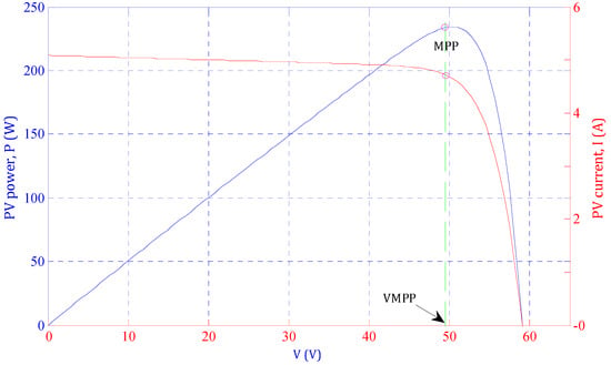
Figure 1.
Characteristic curves of PV module.
To track the optimal power point, numerous maximum power point tracking (MPPT) techniques have been presented through interfaced power electronic circuits [5,6,7]. These MPPT algorithms vary in many aspects, such as tracking efficiency, system dynamic response (system settling time and overshoot), cost, and the required implementation equipment. An analysis of more than 30 different MPPT topologies is illustrated in [7,8]. Among the different MPPT topologies, perturbation and observation (P&O) [9,10,11,12,13,14,15] and incremental conductance (IncCond) [16,17,18,19] MPPT techniques are the most common topologies due to their simplicity, low implementation cost, and direct operation as a result of their independency on PV array parameters. In addition, different MPPT techniques have been proposed based on the parameters of the array, such as the fractional short-circuit current that predicts the location of optimal power from the short-circuit current [14,20], fractional open-circuit voltage that estimates the MPP from the array open-circuit voltage [21], fuzzy logic control-based tracker [22,23], neural network control-based algorithm [24], model-predictive control-based algorithm [25], and the sliding mode control-based MPPT techniques [26,27]. These tracking topologies are iterative MPPT topologies, which track the MPP with high precision under uniform irradiance conditions. However, these topologies suffer from slow response under load change and fast-changing weather conditions. In addition, the MPP spends a large execution time for MPPT control decision, which slows the system tracking response. In [28], an enhanced P&O technique has been presented to improve the PV system tracking operation under fast-changing irradiance conditions. In this control technique, the I-V curve of PV array has been used to differentiate between the irradiance change and operating point perturbation. However, this topology exhibits a slow system dynamic response with high contained steady-state oscillations. Moreover, an improved IncCond MPPT algorithm has been proposed in [16], which applies an allowable error level to improve the dynamic response of the conventional MPPT strategy under fast-changing irradiance conditions. However, it executes complex calculations that slow the system response. In [29], a modified IncCond strategy has been presented that efficiently tracks the optimal power point under fast-changing irradiance conditions. The presented topology improves the steady-state oscillations. However, the algorithm implements this function through complex computations that slows the system dynamic response. In [10], a modified P&O MPPT technique has been recommended to improve the tracking efficiency. However, the proposed controller slows the system response to the long computational execution time. In [30], the basic IncCond MPPT technique has been implemented through Cuk converter, which directly perturbs the duty-cycle of the Cuk converter to track the MPP until the optimal power point location is reached. However, it uses the conventional fixed step-size voltage perturbation that slows the system dynamic response and decreases the system tracking efficiency. Therefore, many research efforts are exerted to improve the tracking efficiency as well as system efficiency by applying a few variable step-size perturbation control algorithms [31,32]. However, the fixed and variable step-size MPPT techniques are applied to improve the tracking efficiency and dynamic behavior of the proposed controller through the DC-DC converter or two-stage DC-AC conversion stage, which increases the system size and cost, and controls complexity. Recently, different MPPT control parameters and topics are raised for the optimal operation of MPPT techniques for modern distribution networks with multi-types of intermittent renewable energy resources [33,34,35].
1.1. Motivation
Stimulated by the aforementioned literature survey, this work aims to apply a modified IncCond MPPT algorithm via a single-stage isolated DC-AC grid-connected differential flyback inverter (DFI). Both MPPT techniques are direct MPPT controllers, which can operate directly with the PV without any pre-stored data requirements [1,2]. In addition, the conventional and modified IncCond MPPT algorithms are compared by a grid-connected PV system through the three-phase isolated DFI. The two MPPT algorithms are applied to the grid-tied PV system under uniform, step-changing, and fast-changing irradiance profiles. The modified MPPT algorithm improves the system dynamic performance by decreasing the system overshoot by 30% and the settling time by 0.03 s compared with the conventional fixed-step MPPT algorithm. Ultimately, the average tracking efficiency of the isolated three-phase grid-integrated PV system is increased from 94.17% to 96.42%.
1.2. Contribution
The significant contributions of this paper are summarized as follows:
- The study provides a simple single-stage three-phase isolated grid-tied PV system through a differential flyback inverter.
- The proposed system is applicable under conventional as well as modified MPPT algorithms and at different irradiance conditions.
- The single-stage operation of the PV system exhibits improved average efficiencies of 94.17% and 96.42% for the conventional and modified algorithms, respectively, with grid isolation for protection purposes.
- The modified MPPT algorithm enhances the system overshoot from 46.45% to 15.38% and the system settling time from 0.062 to 0.035 s.
- The paper exhibits a simple, low-cost, and efficient single-stage three-phase isolated grid-tied PV system through DFI with a 1:2 voltage boosting property.
1.3. Organization
This paper is organized into the following sections. Section 2 illustrates the PV array model with a detailed analysis of PV array specifications. Section 3 analyzes the single-stage three-phase DFI circuit structure and operation, whereas the single-stage conventional and modified IncCond MPPT techniques are explained in Section 4. The system specifications and results considering the conventional and modified single-stage IncCond MPPT algorithms are deeply analyzed in Section 5. Finally, the conclusions are provided in Section 6.
2. Solar Cell Modeling
In general, different mathematical modeling topologies are presented for the solar cell, which form the basic constructional element in the PV array [3]. A single-diode model has been used for simplicity purposes as depicted in Figure 2. The solar cell voltage-current mathematical relationship formula is as follows [1]:
where
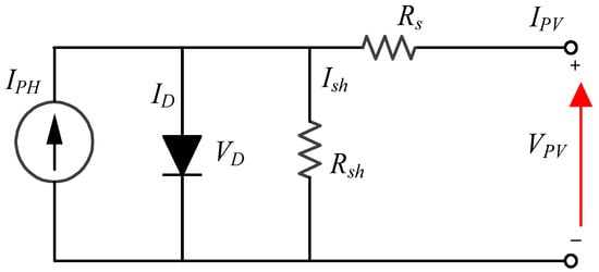
Figure 2.
Solar cell model.
- IPh: light-produced current/photocurrent (A).
- ISat: reverse saturation-current (A).
- q: electron charge (C).
- VPV: solar-cell output-voltage (V).
- IPV: solar-cell output-current (A).
- RS and RSh: series and shunt resistors (Ω), respectively.
- A: P-N junction ideality-factor.
- K: Boltzmann’s constant (1.38 × 10⁻²³ J/K)
- T: solar-cell temperature (K)
In addition, the produced photo-current depends on the level of irradiance (G) and the cell ambient temperature (T) as follows [2]:
where Isc* is the short-circuit current of PV array at standard temperature and irradiation conditions (STICs) (T* = 298 K, G* = 1000 W/m2) and Ki is the PV array temperature co-efficient. In addition, the reverse saturation current is related to the cell temperature as follows [2]:
where Voc*, Kv, and Vt are the cell open-circuit voltage at STICs, open-circuit voltage co-efficient, and the thermal voltage (Vt = K·T/q), respectively.
For a PV array combining series-connected cells of Ns per string and parallel-connected strings of Np, the PV array generated output-current can be formulated as follows [36]:
Moreover, Canadian solar module CSP-220M PV is utilized in the proposed single-stage grid-tied system, where its characteristics under a uniform irradiance profile (1000 W/m2) are depicted in Table 1. In addition, the system characteristics are directly related to the applied irradiance level as depicted in Figure 3.

Table 1.
Canadian solar module characteristics CSP-220M PV.
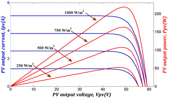
Figure 3.
Output characteristics of the solar cell under different irradiance levels [1].
3. Three-Phase Single-Stage DFI
Figure 4 shows the three-phase DFI circuit structure, which consists of three parallel-connected input and differential-connected output flyback converter modules. Therefore, each module utilizes two switches (SMx, SRx), high frequency transformer (Trx), and output capacitor (Cox), where x = a, b, or c. Each flyback module temporarily transfers the input power to the secondary side with voltage bucking/boosting property as depicted in the operational modes in Figure 5. In addition, a variable duty-cycle is applied to control each flyback module under a wide range of duty-cycle changes to form DC output-voltage over module-output capacitors, which have a sinusoidal envelope and 120° phase-shift between the different modules (see Figure 4). Consequently, the differential connection between the flyback modules cancels the DC-voltage component and forms sinusoidal voltage waveforms at the grid terminals. Moreover, the success of the single-stage DFI depends on the flyback HFT design. As the DFI transfers the power temporarily to the grid, the HFT performs two main operational functions: (a) Storage element for the input power over the HFT magnetizing inductance, LM, (b) Galvanic isolation for grid integration applications. In addition, the HFT offers further voltage bucking/boosting properties.
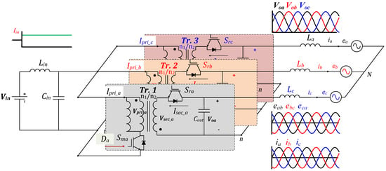
Figure 4.
Differential-based three-phase flyback inverter.
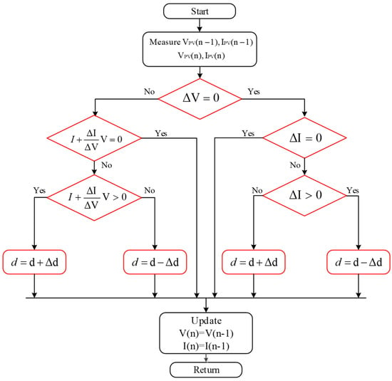
Figure 5.
Conventional IncCond MPPT algorithm flowchart.
Different modulation schemes are used to control variable duty-cycle inverter topologies as reported in [37,38]. The grid-tied DFI synthesizes a sinusoidal grid current deceived with low-order harmonics due to the voltage boosting property with a mismatch between the converter modules and the input-to-output nonlinear relationship [39]. Therefore, the continuous modulation scheme (CMS) combined with the static linearization method (SLM) is used for low-frequency odd harmonics elimination in the grid-injected currents [40]. However, a feedback separate compensation loop is required for NS low-frequency even harmonics compensation. In addition, the CMS-based control scheme improves the input current ripple for PV applications as well as grid current THD to follow the IEEE and IEC standard harmonic limitations [41,42].
4. Incremental Conductance MPPT
The incremental conductance is a common MPPT technique that tracks the optimal PV array power directly without pre-defined information about the PV system [1]. It tracks the MPP by comparing the addition of the instantaneous conductance (I/V) and the incremental conductance (Δi/Δv) with zero to decide the location of the MPP (I/V + Δi/Δv). The slope of the solar array P-V curve is positive on the left side of MPP, zero at the MPP, and negative on the right side of MPP. Consequently, the MPPT algorithm adjusts the PV array voltage to control the operating point location. Therefore, when the P-V curve slope is negative, the controller moves the operating point to the left side toward the MPP locations by decreasing the PV array voltage. Similarly, when the slope is positive, it increases the PV array voltage to move the operating point to the right side toward the MPP. Finally, as a null slope is reached, the voltage adjustment stops and the MPP is reached as depicted in the control algorithm in Figure 5. This simple and conventional MPPT algorithm tracks the MPP effectively at a uniform irradiance condition. However, it causes oscillations around the steady-state location and can easily divert the MPPT under fast-changing irradiance conditions. This conventional algorithm has the former handicap since it cannot differentiate between the fast-changing irradiance effects and the MPP location change.
Considering the former drawbacks, a modified IncCond MPPT technique is applied to track the optimal operating point location for efficient MPPT as shown in the algorithm flowchart in Figure 6 [3]. The modified algorithm tracks the MPP efficiently by checking the current variation sign with voltage variations. If the voltage perturbation results in current variations of the same sign, a sudden irradiance change is applied to the solar array (see Figure 6). Otherwise, the conventional IncCond technique is adequate to track the optimal MPP efficiently. In addition, the modified IncCond MPPT technique uses different step sizes in the PV array perturbation according to the location of the MPP on the P-V curve. Therefore, the closer the operating point to the MPP, the smaller the step size of voltage perturbation as depicted in the modified technique flowchart in Figure 6.
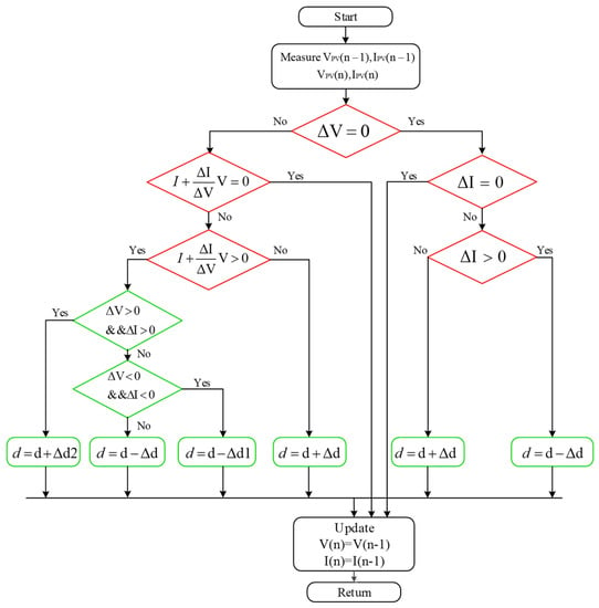
Figure 6.
Modified IncCond MPPT algorithm flowchart.
5. System Results and Discussion
5.1. System Specifications
Based on the aforementioned analysis and modeling of different parts of the proposed system, the PSIM software is used to simulate the single-stage grid-tied PV system combined with the MPPT algorithm. In addition, the paper did not consider the experimental system verifications due to the unavailability of the system prototype at this moment, which will be considered in the future with low power capacity. This section illustrates the validation of the three-phase DFI using CMS control techniques through 200 V, 5 kW, and 50 kHz switching frequencies as the down-scale system for central-type PV inverters. The DFI closed-loop control scheme with the main and secondary control-loops is described in Figure 7. The parameters of the grid-tied system are listed in Table 2, which consists of the input PV array-based Canadian solar module with the parameters in Table 1, the DFI power-stage, and the grid-tied current filter (grid-inductance). Moreover, a stringent designed snubber-circuit is used to mitigate the high voltage spikes over the power switches.
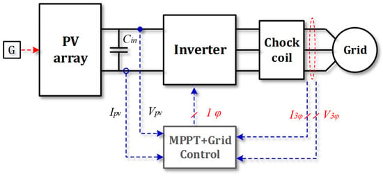
Figure 7.
Proposed DFI control scheme.

Table 2.
Overall DFI system parameters.
In addition, this section aims to exhibit the performance of the conventional and proposed IncCond MPPT techniques through a compact three-phase DFI under a uniform irradiance profile and constant temperature fixed at 25 °C. Moreover, the fast-changing irradiance profile is applied to the proposed grid-tied system to investigate the MPPT response under stringent irradiance conditions. Furthermore, the DFI connects the PV system to the utility grid with a voltage boosting factor of (2), as shown in the input and grid voltage specifications listed in Table 2. The system circuit diagram has been illustrated in Figure 4 and the duty-cycle increments are listed in Table 2.
5.2. System Results
First, the proposed single-stage grid-tied PV system is tested under the conventional and modified IncCond MPPT techniques using a step-change uniform irradiance profile, as depicted in Figure 8. The solar irradiance profile is depicted in Figure 8a. The solar irradiance is uniform at 1000 W/m2 for 1 s of the operating period, which is step-changed to 500 W/m2 for another 1 s. Figure 8b shows the PV output-voltage using the conventional and modified IncCond MPPT techniques compared with the reference PV voltage, which is plotted in red color as depicted in the legend of each waveform. In addition, the MPP reference voltage variations are small compared to the variations in the actual waveforms. The results of the two tracking techniques are matched. However, the modified IncCond algorithm improves the system settling time and overshoot from (0.062 s and 46.15%) for the conventional algorithm to (0.035 s and 15.38%), respectively, as shown in the two zoomed regions. In addition, the d-axis current of the conventional and modified MPPT techniques are compared with the reference value as depicted in Figure 8c,d, respectively. Therefore, it proves the single-stage IncCond-based MPPT operation of the proposed grid-tied PV system under the two tracking algorithms using a step-changing irradiance profile. In addition, the settling time and overshoot of the d-axis current is improved using the modified IncCond from (0.062 s and 46.15%) for the conventional technique to (0.035 s and 15.38%), respectively.
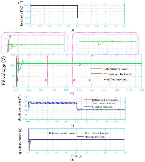
Figure 8.
Grid-tied system results under the step-change uniform irradiance profile. (a) Step-change irradiance profile; (b) PV output-voltage under the two IncCond MPPT techniques; (c) grid-injected d-axis current; (d) grid-injected q-axis current.
Furthermore, the fast-changing irradiance profile is applied to the single-stage grid-connected PV system to reveal the tracking response of the conventional and modified IncCond MPPT techniques under these hard and fast-changing irradiance conditions. The fast-changing irradiance profile is depicted in Figure 9a,b. As can be seen, the PV output-voltage under the conventional and modified MPPT techniques is compared with the reference value. The system output-voltage using the modified IncCond MPPT technique shows an improved response compared with the conventional one. The d-axis current of the conventional and modified MPPT algorithms is compared with the reference value in Figure 9a,c comparison of the q-axis current is illustrated in Figure 9d.
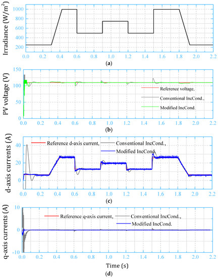
Figure 9.
Grid-tied system results under the fast-changing irradiance profile. (a) Step-change irradiance profile; (b) PV output-voltage under the two IncCond MPPT techniques; (c) grid-injected d-axis current; (d) grid-injected q-axis current.
It is clear that the PV-side and grid-side results guaranteed the single-stage DC-AC PV system under the conventional and modified IncCond MPPT techniques. Moreover, the modified algorithm exhibits a better performance and dynamic response than the conventional algorithm’s poor response. It improves the classical tracking behavior by decreasing the system settling time and dynamic overshoot. In addition, Figure 10 shows the FFT harmonic spectrum of the grid-injected current. The grid current THD is (3.95%), which follows the IEC-61000 and IEEE-519 harmonic standard limits.
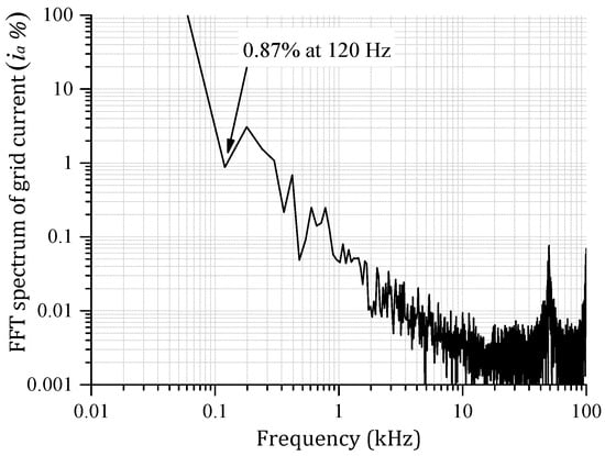
Figure 10.
Grid current FFT harmonic spectrum (3.95%).
In addition, Figure 11 shows the instantaneous grid-injected powers and instantaneous tracking efficiency of the proposed single-stage PV system based on the following formula [1]:
where ηT is the instantaneous tracking efficiency, PG is the grid-injected power, and Pth refers to the theoretical grid-injected power. In addition, the average tracking efficiency can be calculated from the following formula [2]:
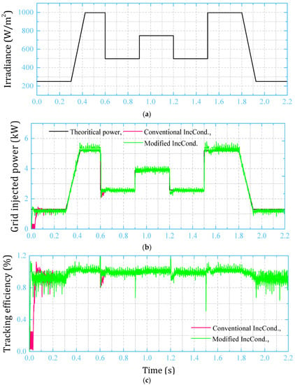
Figure 11.
Grid current FFT harmonic spectrum. (a) Fast-changing irradiance profile; (b) grid-injected power comparison with theoretical power; (c) PV system tracking efficiency comparison.
The grid-injected power of the conventional and modified MPPT techniques is compared with the theoretical grid-injected power in Figure 11a. Moreover, Figure 11b shows the instantaneous tracking efficiency of the two IncCond-based MPPT algorithms based on Equation (5). Therefore, the modified algorithm improved the system average efficiency from 94.46% to 96.41%, which improved the system efficiency by 2.25%. Finally, the aforementioned results guaranteed the single-stage IncCond MPPT algorithm operation for the grid-tied PV system through the three-phase DFI.
6. Conclusions
This paper proposes a single-stage incremental conductance-based MPPT technique for the grid-tied PV system through the three-phase DC-AC isolated DFI. The proposed system decreases the required number of operational stages, components, and footprints. In addition, the system operation has been investigated by considering the conventional and modified IncCond MPPT algorithms. Moreover, the two tracking techniques are applied to the PV system under the step-change uniform irradiance as well as fast-changing irradiance profile. The system results guaranteed the single-stage operation of the proposed grid-tied PV system under the two MPPT techniques. Furthermore, the proposed modified IncCond algorithm exhibits an improved dynamic response compared with the conventional technique. It improves the system overshoot and settling time by (0.027 s and 30.77%), respectively. Ultimately, the tracking efficiency of the proposed single-stage grid-tied PV system has been improved from (94.16%) for the conventional IncCond algorithm to (96.41%) for the modified algorithm, as listed in Table 3. As a result, this paper achieved the single-stage MPPT operation using two techniques with the efficiency enhancement and minimized inverter footprint, which is applicable for industrial central-type PV tracking systems. Finally, the experimental verification of the proposed system will be investigated in future work considering a low-scale system capacity and standalone operation.

Table 3.
Conventional vs. modified IncCond MPPT technique comparison at 1000 W/m2 and 25 °C.
Author Contributions
Conceptualization, A.I.M.A., Z.M.A., M.A.S. and M.A.M.; methodology, A.I.M.A.; software, A.I.M.A.; validation, A.I.M.A., Z.M.A., M.A.S., A.A., A.F. and M.A.M.; formal analysis, A.I.M.A., Z.M.A., M.A.S., A.A., A.F. and M.A.M.; investigation, A.I.M.A., Z.M.A., M.A.S., A.A., A.F. and M.A.M.; resources, A.I.M.A., Z.M.A., M.A.S., A.A., A.F. and M.A.M.; data curation, A.I.M.A., Z.M.A., M.A.S., A.A., A.F. and M.A.M.; writing—original draft preparation, A.I.M.A.; writing—review and editing, A.I.M.A., Z.M.A., M.A.S., A.A., A.F. and M.A.M.; visualization, A.I.M.A., Z.M.A., M.A.S., A.A., A.F. and M.A.M.; supervision, A.I.M.A., Z.M.A., M.A.S., A.A., A.F. and M.A.M. All authors have read and agreed to the published version of the manuscript.
Funding
This research has been funded by Scientific Research Deanship at the University of Ha’il—Saudi Arabia through project number RG-21079.
Institutional Review Board Statement
Not applicable.
Informed Consent Statement
Not applicable.
Data Availability Statement
Not applicable.
Conflicts of Interest
The authors declare no conflict of interest.
References
- Ali, A.I.; Sayed, M.A.; Mohamed, E.E. Modified efficient perturb and observe maximum power point tracking technique for grid-tied PV system. Int. J. Electr. Power Energy Syst. 2018, 99, 192–202. [Google Scholar] [CrossRef]
- Ali, A.I.M.; Mohamed, H.R.A. Improved P&O MPPT algorithm with efficient open-circuit voltage estimation for two-stage grid-integrated PV system under realistic solar radiation. Int. J. Electr. Power Energy Syst. 2022, 137, 107805. [Google Scholar]
- Eltamaly, A.M.; Mohamed, M.A.; Abo-Khalil, A.G. Design and Comprehensive Analysis of Maximum Power Point Tracking Techniques in Photovoltaic Systems. In Advanced Technologies for Solar Photovoltaics Energy Systems; Springer: Cham, Switzerland, 2021; pp. 253–284. [Google Scholar]
- Chen, W.; Liu, B.; Nazir, M.S.; Abdalla, A.N.; Mohamed, M.A.; Ding, Z.; Bhutta, M.S.; Gul, M. An Energy Storage Assessment: Using Frequency Modulation Approach to Capture Optimal Coordination. Sustainability 2022, 14, 8510. [Google Scholar] [CrossRef]
- Rao, C.; Hajjiah, A.; El-Meligy, M.A.; Sharaf, M.; Soliman, A.T.; Mohamed, M.A. A novel high-gain soft-switching DC-DC converter with improved P&O MPPT for photovoltaic applications. IEEE Access 2021, 9, 58790–58806. [Google Scholar]
- Subudhi, B.; Pradhan, R. A comparative study on maximum power point tracking techniques for photovoltaic power systems. IEEE Trans. Sustain. Energy 2012, 4, 89–98. [Google Scholar] [CrossRef]
- Ali, M.N.; Mahmoud, K.; Lehtonen, M.; Darwish, M.M. An efficient fuzzy-logic based variable-step incremental conductance MPPT method for grid-connected PV systems. IEEE Access 2021, 9, 26420–26430. [Google Scholar] [CrossRef]
- Hanzaei, S.H.; Gorji, S.A.; Ektesabi, M. A scheme-based review of MPPT techniques with respect to input variables including solar irradiance and PV arrays’ temperature. IEEE Access 2020, 8, 182229–182239. [Google Scholar] [CrossRef]
- Bianconi, E.; Calvente, J.; Giral, R.; Mamarelis, E.; Petrone, G.; Ramos-Paja, C.A.; Spagnuolo, G.; Vitelli, M. Perturb and observe MPPT algorithm with a current controller based on the sliding mode. Int. J. Electr. Power Energy Syst. 2013, 44, 346–356. [Google Scholar] [CrossRef]
- Ahmed, J.; Salam, Z. An improved perturb and observe (P&O) maximum power point tracking (MPPT) algorithm for higher efficiency. Appl. Energy 2015, 150, 97–108. [Google Scholar]
- Tafticht, T.; Agbossou, K.; Doumbia, M.; Cheriti, A. An improved maximum power point tracking method for photovoltaic systems. Renew. Energy 2008, 33, 1508–1516. [Google Scholar] [CrossRef]
- Ishaque, K.; Salam, Z.; Lauss, G. The performance of perturb and observe and incremental conductance maximum power point tracking method under dynamic weather conditions. Appl. Energy 2014, 119, 228–236. [Google Scholar] [CrossRef]
- Femia, N.; Petrone, G.; Spagnuolo, G.; Vitelli, M. Optimization of perturb and observe maximum power point tracking method. IEEE Trans. Power Electron. 2005, 20, 963–973. [Google Scholar] [CrossRef]
- Kollimalla, S.K.; Mishra, M.K. A new adaptive P&O MPPT algorithm based on FSCC method for photovoltaic system. In Proceedings of the 2013 International Conference on Circuits, Power and Computing Technologies (ICCPCT), Nagercoil, India, 21–22 March 2013; pp. 406–411. [Google Scholar]
- Kamran, M.; Mudassar, M.; Fazal, M.R.; Asghar, M.U.; Bilal, M.; Asghar, R. Implementation of improved Perturb & Observe MPPT technique with confined search space for standalone photovoltaic system. J. King Saud Univ. Eng. Sci. 2020, 32, 432–441. [Google Scholar]
- Elgendy, M.A.; Zahawi, B.; Atkinson, D.J. Assessment of the incremental conductance maximum power point tracking algorithm. IEEE Trans. Sustain. Energy 2012, 4, 108–117. [Google Scholar] [CrossRef]
- Sayed, M.A.; Mohamed, E.; Ali, A. Maximum power point tracking technique for grid tie PV system. In Proceedings of the 7th International Middle-East Power System Conference, (MEPCON’15), Mansoura, Egypt, 15–17 December 2015; Mansoura University: Mansoura, Egypt, 2015. [Google Scholar]
- Lin, C.-H.; Huang, C.-H.; Du, Y.-C.; Chen, J.-L. Maximum photovoltaic power tracking for the PV array using the fractional-order incremental conductance method. Appl. Energy 2011, 88, 4840–4847. [Google Scholar] [CrossRef]
- Radjai, T.; Rahmani, L.; Mekhilef, S.; Gaubert, J.P. Implementation of a modified incremental conductance MPPT algorithm with direct control based on a fuzzy duty cycle change estimator using dSPACE. Sol. Energy 2014, 110, 325–337. [Google Scholar] [CrossRef]
- Hiyama, T.; Kouzuma, S.; Imakubo, T. Identification of optimal operating point of PV modules using neural network for real time maximum power tracking control. IEEE Trans. Energy Convers. 1995, 10, 360–367. [Google Scholar] [CrossRef]
- Ahmad, J. A fractional open circuit voltage based maximum power point tracker for photovoltaic arrays. In Proceedings of the 2010 2nd International Conference on Software Technology and Engineering, San Juan, PR, USA, 3–5 October 2010; pp. V1-247–V1-250. [Google Scholar]
- Alajmi, B.N.; Ahmed, K.H.; Finney, S.J.; Williams, B.W. Fuzzy-logic-control approach of a modified hill-climbing method for maximum power point in microgrid standalone photovoltaic system. IEEE Trans. Power Electron. 2010, 26, 1022–1030. [Google Scholar] [CrossRef]
- Salam, Z.; Ahmed, J.; Merugu, B.S. The application of soft computing methods for MPPT of PV system: A technological and status review. Appl. Energy 2013, 107, 135–148. [Google Scholar] [CrossRef]
- Rai, A.K.; Kaushika, N.; Singh, B.; Agarwal, N. Simulation model of ANN based maximum power point tracking controller for solar PV system. Sol. Energy Mater. Sol. Cells 2011, 95, 773–778. [Google Scholar] [CrossRef]
- Ali, A.I.; Mohamed, E.E.; Youssef, A.-R. MPPT algorithm for grid-connected photovoltaic generation systems via model predictive controller. In Proceedings of the 2017 Nineteenth International Middle East Power Systems Conference (MEPCON), Cairo, Egypt, 19–21 December 2017; pp. 895–900. [Google Scholar]
- Farhat, M.; Barambones, O.; Sbita, L. Real-time efficiency boosting for PV systems using MPPT based on sliding mode. Energy Procedia 2015, 75, 361–366. [Google Scholar] [CrossRef][Green Version]
- Farhat, M.; Barambones, O.; Sbita, L. A new maximum power point method based on a sliding mode approach for solar energy harvesting. Appl. Energy 2017, 185, 1185–1198. [Google Scholar] [CrossRef]
- Ghassami, A.A.; Sadeghzadeh, S.M.; Soleimani, A. A high performance maximum power point tracker for PV systems. Int. J. Electr. Power Energy Syst. 2013, 53, 237–243. [Google Scholar] [CrossRef]
- Tey, K.S.; Mekhilef, S. Modified incremental conductance MPPT algorithm to mitigate inaccurate responses under fast-changing solar irradiation level. Sol. Energy 2014, 101, 333–342. [Google Scholar] [CrossRef]
- Safari, A.; Mekhilef, S. Implementation of incremental conductance method with direct control. In Proceedings of the TENCON 2011—2011 IEEE Region 10 Conference, Bali, Indonesia, 21–24 November 2011; pp. 944–948. [Google Scholar]
- Liu, F.; Duan, S.; Liu, F.; Liu, B.; Kang, Y. A variable step size INC MPPT method for PV systems. IEEE Trans. Ind. Electron. 2008, 55, 2622–2628. [Google Scholar]
- Yau, H.-T.; Liang, Q.-C.; Hsieh, C.-T. Maximum power point tracking and optimal Li-ion battery charging control for photovoltaic charging system. Comput. Math. Appl. 2012, 64, 822–832. [Google Scholar] [CrossRef][Green Version]
- Zhou, S.; Han, Y.; Yang, P.; Mahmoud, K.; Lehtonen, M.; Darwish, M.M.; Zalhaf, A.S. An optimal network constraint-based joint expansion planning model for modern distribution networks with multi-types intermittent RERs. Renew. Energy 2022, 194, 137–151. [Google Scholar] [CrossRef]
- Al-Gabalawy, M.; Mahmoud, K.; Darwish, M.M.; Dawson, J.A.; Lehtonen, M.; Hosny, N.S. Reliable and robust observer for simultaneously estimating state-of-charge and state-of-health of lifepo4 batteries. Appl. Sci. 2021, 11, 3609. [Google Scholar] [CrossRef]
- Ghoneim, S.S.; Mahmoud, K.; Darwish, M.M. Effective Transmission Congestion Management via Optimal DG Capacity Using Hybrid Swarm Optimization for Contemporary Power System Operations. IEEE Access 2022, 10, 71091–71106. [Google Scholar]
- Ali, A.I.; Sayed, M.A.; Mohamed, E.E. Maximum Power Point Tracking technique applied on partial shaded grid connected PV system. In Proceedings of the 2016 Eighteenth International Middle East Power Systems Conference (MEPCON), Cairo, Egypt, 27–29 December 2016; pp. 656–663. [Google Scholar]
- Diab, M.; Elserougi, A.; Abdel-Khalik, A.; Massoud, A.; Ahmed, S. Modified modulation scheme for photovoltaic fed grid-connected three-phase boost inverter. In Proceedings of the IECON 2013-39th Annual Conference of the IEEE Industrial Electronics Society, Vienna, Austria, 10–13 November 2013; pp. 1735–1740. [Google Scholar]
- Ali, A.I.M.; Takeshita, T.; Sayed, M.A. In depth mathematical-analysis and experimentation of high-power SiC-FET based single-stage three-phase differential-based flyback inverter with practical design issues for grid-tied applications. Int. J. Electr. Power Energy Syst. 2022, 140, 108041. [Google Scholar] [CrossRef]
- Mehrnami, S.; Mazumder, S.K.; Soni, H. Modulation scheme for three-phase differential-mode Ćuk inverter. IEEE Trans. Power Electron. 2015, 31, 2654–2668. [Google Scholar] [CrossRef]
- Darwish, A.; Massoud, A.M.; Holliday, D.; Ahmed, S.; Williams, B. Single-stage three-phase differential-mode buck-boost inverters with continuous input current for PV applications. IEEE Trans. Power Electron. 2016, 31, 8218–8236. [Google Scholar] [CrossRef]
- Ali, A.I.M.; Tuan, C.A.; Takeshita, T.; Sayed, M.A.; Alaas, Z.M. Modular Single-Stage Three-Phase Flyback Differential Inverter for Medium/High-Power Grid Integrated Applications. Sensors 2022, 22, 2064. [Google Scholar] [CrossRef] [PubMed]
- Hammami, M.; Grandi, G. A single-phase multilevel PV generation system with an improved ripple correlation control MPPT algorithm. Energies 2017, 10, 2037. [Google Scholar] [CrossRef]
- Zurbriggen, I.G.; Ordonez, M. PV energy harvesting under extremely fast changing irradiance: State-plane direct MPPT. IEEE Trans. Ind. Electron. 2018, 66, 1852–1861. [Google Scholar] [CrossRef]
Publisher’s Note: MDPI stays neutral with regard to jurisdictional claims in published maps and institutional affiliations. |
© 2022 by the authors. Licensee MDPI, Basel, Switzerland. This article is an open access article distributed under the terms and conditions of the Creative Commons Attribution (CC BY) license (https://creativecommons.org/licenses/by/4.0/).