Review

A Comprehensive Review on Recent Advancements in Thermochemical Processes for Clean Hydrogen Production to Decarbonize the Energy Sector

1
Department of Mechanical Engineering, Rajshahi University of Engineering and Technology, Rajshahi 6204, Bangladesh
2
Department of Agriculture, Hajee Mohammad Danesh Science and Technology University, Dinajpur 5200, Bangladesh
*
Author to whom correspondence should be addressed.
Sustainability 2022, 14(18), 11206; https://doi.org/10.3390/su141811206
Submission received: 28 July 2022 / Revised: 25 August 2022 / Accepted: 1 September 2022 / Published: 7 September 2022
(This article belongs to the Special Issue Clean Hydrogen for Decarbonizing Energy Sector)

Abstract

:
Hydrogen is a source of clean energy as it can produce electricity and heat with water as a by-product and no carbon content is emitted when hydrogen is used as burning fuel in a fuel cell. Hydrogen is a potential energy carrier and powerful fuel as it has high flammability, fast flame speed, no carbon content, and no emission of pollutants. Hydrogen production is possible through different technologies by utilizing several feedstock materials, but the main concern in recent years is to reduce the emission of carbon dioxide and other greenhouse gases from energy sectors. Hydrogen production by thermochemical conversion of biomass and greenhouse gases has achieved much attention as researchers have developed several novel thermochemical methods which can be operated with low cost and high efficiency in an environmentally friendly way. This review explained the novel technologies which are being developed for thermochemical hydrogen production with minimum or zero carbon emission. The main concern of this paper was to review the advancements in hydrogen production technologies and to discuss different novel catalysts and novel CO2-absorbent materials which can enhance the hydrogen production rate with zero carbon emission. Recent developments in thermochemical hydrogen production technologies were discussed in this paper. Biomass gasification and pyrolysis, steam methane reforming, and thermal plasma are promising thermochemical processes which can be further enhanced by using catalysts and sorbents. This paper also reviewed the developments and influences of different catalysts and sorbents to understand their suitability for continuous clean industrial hydrogen production.

1. Introduction

The constancy of population growth and urbanization accelerates the demand of energy, and the consumption of energy is also increasing [1,2,3]. Different sources have been used from previous years to produce energy. Among those energy sources, the most conventional energy resource is fossil fuels, which have a depleting consistency of extraction and limitation in amount, and there has been an over-dependency on fossil fuel for power generation in the past years [4,5,6,7]. With increasing consumption rates and demand for energy, extraction and use of hydrocarbons (fossil fuel) have been accelerated over the last few decades and, as a result, incrementation in emissions such as carbon dioxide, particulate matter, and oxides of nitrogen and oxygen pollute the atmosphere, which causes global warming, the most featured problem in recent time [8,9,10,11]. Emphasizing global security, energy sustainability, and to protect the environment, it is time to properly utilize clean energy, which has zero carbon emission and impedes the accumulation of greenhouse gases in the global atmosphere [12,13,14].
Renewable energy resources are promising potential options for the security of humans and the environment, and healthy and sustainable economic growth [15,16,17,18]. International researchers and experts have categorized renewable energy as new traditional renewable energy because a few years ago, giant hydro power plants and direct burning of biomass were considered as the main renewable sources of energy, whereas in recent years wind energy, solar energy, small hydro plants, geothermal energy, hydrogen energy, and biomass energy are [19,20,21,22]. The main challenge to utilize these renewable resources is the lack of awareness, power storage systems, purification processes, and the variable nature of these sources [23,24,25]. More research is required to improve the storage systems with proper purification technologies as well as to solve the safety issues to adapt to these renewable resources as the penetration of renewable energy sources is increasing with time. Besides these, better technologies are required for shifting the produced energy from the production unit to utilization processing [26,27,28].
A worldwide accepted energy carrier for storing renewable energy is hydrogen, which has the potential for its storability, source independency, transportability, and high energy content per mass; due to these advantages, the applications of hydrogen energy are increasing with time [28,29,30,31]. The applications of hydrogen energy increase with time and among those portable electronics, fertilizer production, and aerospace applications fuel cell in automotive industries are some sectors where the potential of hydrogen fuel can be utilized [32,33,34,35]. Hydrogen can also be considered an ineluctable choice for electricity, power, and as a heat generation source for its cost-effectiveness, abundance, and usability [36,37,38,39]. Moreover, hydrogen is considered clean energy because there is no carbon emission as well as no emission of particulate matter [40,41]. A little amount of nitrogen oxide emission can occur due to burning hydrogen at very high temperatures, but when it is utilized at low temperatures, such as in fuel cells, there is no emission [42,43].
Hydrogen production is possible from different resources such as non-renewable and renewable sources using different feedstock materials, methods, and technologies. Coal, crude oil, and natural gas are the main sources that are non-renewable and biomass, municipal solid waste, and agricultural waste are the major sources that are considered renewable sources for hydrogen production by implementing different hydrogen production technologies [44,45,46]. Researchers have developed several technologies to produce clean hydrogen with low cost and low carbon emission [47]. The most thriving technologies are thermochemical, biolysis, electrolysis, radiolysis, electro-photolysis, and photolysis. In this paper, different thermochemical processes were reviewed, such as steam reforming, autothermal reforming, biomass gasification, biomass pyrolysis, thermal plasma, and several catalytic effects of these processes. Researchers are working to develop such technology to reduce CO2 emissions and to establish sustainable, environment-friendly ways for producing hydrogen by converting biomass, agricultural residues, municipal solid waste, and several hydrocarbons. In recent years, researchers are working to decarbonize the energy sector to make it more environmentally friendly and for this, efficient ways need to be developed for hydrogen production, which can reduce the amount of greenhouse emissions.
Thermochemical conversion of biomass to produce hydrogen is much more advantageous as different thermochemical conversion technologies can be implemented for converting biomass into hydrogen-rich syngas and bio-oils [48,49]. Among these technologies, gasification and pyrolysis of biomass are in the leading position due to their ease of feed (biomass) conversion procedure and ability to convert different types of biomasses such as waste, agricultural residue, wheat straw, sugarcane bagasse, and rice husk [50,51,52,53]. Moreover, utilization of biomass through thermochemical conversion can eliminate the combustion of fossil fuels, which can bring potential ways to mitigate the greenhouse gas effect by minimizing carbon capture [54,55,56]. The thermochemical conversion of biomass, hydrocarbon, and other feedstock materials can produce gaseous components which can hamper the environment and human life. To reduce such bad emissions, different reduction and utilization processes are required and to fulfill these requirements; researchers have developed several technologies which include applying different CO2 sorbent materials, promoting CO2 reaction with methane and other hydrocarbons, etc. [57]. A higher amount of hydrogen production is possible by integrating suitable processes, known as a multistage hydrogen production technology. Catalyst increases hydrogen production rate and minimizes tar and other waste production by promoting feedstock conversion processes. Besides, catalysts allow performing the conversion process at a lower temperature, which minimizes the requirement of a high energy supply [58]. In this paper, different thermochemical conversion technologies for different feedstock materials, several catalysts, several sorbents, and different catalyst supporters at different operating conditions were reviewed elaborately.

2. Thermochemical Technologies for Hydrogen Production

2.1. Partial Oxidation Method

Partial oxidation is a popular hydrogen production technology where natural gas and hydrocarbons are used as raw materials; this methodology consists of a partial oxidation reformer, air separation unit, feedstock treatment unit, and purification unit. Pure oxygen comes from the air separation unit and enters the reformer where feedstock material is heated and synthesis gas is produced following the following reaction:
C n H m + n 2 O 2 n CO + n 2 H 2
If there is a sufficient amount of oxygen supplied from the air separation unit, complete oxidation of hydrocarbons and natural gas is possible and this occurs as the main reaction:
CH 4 + 2 O 2 CO 2 + 2 H 2 O
A schematic process diagram is shown in Figure 1 that shows partial oxidation process for hydrogen production. Sometimes, the dry reforming process, also known as carbon dioxide reforming, can happen as a side reaction at the time of partial oxidation and, as a result, more synthesis gas is produced. Additionally, this side reaction occurs following the following reaction formula:
CH 4 + CO 2 2 CO + 2 H 2
C 14 H 30 + 7 O 2 14 CO + 15 H 2
Partial oxidation reactions of heavy fuel oil take place under very high temperatures (1250–1400 °C) and very high pressures. Natural gas is considered the major feedstock in partial oxidation; however, there are some novel and promising feedstock materials which are used in partial oxidation. Among them, the long-chain alkane, which is present in hexane, has achieved a lot of attention for its use as a feedstock material in partial oxidation [59]. To obtain more effectiveness in partial oxidation, studying more process conditions and parameters and different simulations is required; numerical analyses and experimental studies have been carried out to achieve a better understanding of the partial oxidation process [60,61,62,63,64]. Supercritical water partial oxidation (SCWPO) is an ecofriendly approach to utilizing organic waste resources, and ethanol is a common model constituent of organic waste. Ren et al. investigated the SCWPO of ethanol in a quartz batch reactor and their results revealed that when increasing the temperature and decreasing the concentration of feed, the amount of gas yield and feed conversion efficiency could be increased [65].

2.2. Pyrolysis of Biomass

Large-scale hydrogen production is possible from biomass, which can improve sustainability in the energy sector. The demand for renewable sources such as biomass is increasing for hydrogen production. Wheat straw, sugarcane bagasse, and rice husk were studied for producing hydrogen by pyrolysis of biomass and steam reforming of end products from pyrolysis. Pyrolysis of biomass is a thermochemical process through which gaseous components that include syngas (CO + H2) and methane, solid char coal, and liquid oil with tars can be produced by heating in a chamber with 650–800 K temperature and 0.1–0.5 MPa pressure [66]. Bio-oil contains organic compounds and is less viscous than tars, which mainly contain free carbon and hydrocarbons. Commercial grade bio-oil can be achieved by purifying crude bio-oil. Carbon-enriched solid biochar can be produced with some impurities such as aromatic compounds in pyrolysis of biomass. A steam reforming process integrated pyrolysis process is shown in Figure 2.
Pyrolysis occurs in the absence of oxygen; however, when partial oxidation is required for adding thermal energy to the system, then some amount of oxygen can be added [67]. Produced methane and other hydrocarbon gases can be utilized by steam-reforming processes, and for further production of hydrogen, the water gas-shift method can be applied. End gas from the WGS unit can be purified in a pressure swing absorption (PSA) system and pure hydrogen gas can be obtained.
C n H m + nH 2 O nCO + ( n + 1 2 m ) H 2
CO + H 2 O CO 2 + H 2
According to the time required and temperature, pyrolysis of biomass can take place in three types: flash pyrolysis, first pyrolysis, and slow pyrolysis. In flash pyrolysis, the heating rate is nearly 2500 °C, the whole process can be finished within 0.1 to 0.5 s, and the characterization of flash pyrolysis occurs when the moderate temperature of 400–500 °C of pyrolysis reaches near 1000 °C. Products from flash pyrolysis are yielded as liquid phase, e.g., bio-oil. Ayhan experimented with flash pyrolysis of tobacco stalk and yellow pine wood and they investigated the effects of temperature on gaseous product and tar yield. Their result indicated that tar yield was decreased and gaseous product yield was increased when the temperature was increased from 675 to 1025 K [68]. Fast pyrolysis, which is relatively close to flash pyrolysis, is performed at heating rates of 10–200 °C per second. Gaseous and liquid phases such as biogas and bio-oil can be produced with the fast pyrolysis process; normally, the resistance time for fast pyrolysis is less than 2 s, whereas for flash pyrolysis the resistance time remains within 0.5 s [69,70]. Arregi et al. studied continuous fast pyrolysis of pine wood sawdust at 500 °C temperature and they also integrated steam reforming of pyrolysis vapors at a temperature range of 550–700 °C. They investigated the temperature effects of steam reforming on hydrogen yield and found that maximum hydrogen yield was possible at a temperature 600 °C and on the steam-to-biomass ratio of 4 [71]. Slow pyrolysis is performed for a relatively long time, which may take up to several days; the operating temperature of this process does not exceed 500 °C and heating rates remain at 0.1–2 °C, which is comparatively much lower than flash pyrolysis and fast pyrolysis processes. Due to the long residence time of slow pyrolysis, char and tars come out as end products in this pyrolysis process. Guerrero et al. experimented with slow pyrolysis of apple pomace to produce hydrogen by integrating absorption-enhanced steam methane reforming (AESMR) with the system where the performed pyrolysis was performed at 300–450 °C and heating rates of 5–20 °C/min. Their result showed that for maximum hydrogen production the optimum temperatures are 400 and 715 °C for pyrolysis and AESMR respectively [72].
The production of hydrogen is largely dependent on catalyst type, feedstock material, time residence, and temperature [73,74]. J. Matras et al. [75] experimented with the performance of biomass pyrolysis for Ni-based catalysts with different supporting materials (ZrO2, Al2O3, CeO2, SiO2, ZrO2 + Al2O3), which was performed at 700 °C in a stirred bed reactor and the highest production of hydrogen was possible for the Ni/ZrO2 catalyst, which was prepared by the impregnation method. It is possible to increase the syngas (CO + H2) production from the pyrolysis of biomass by extending the residence period of developed species to encourage secondary reactions [76]. Tar produced by pyrolysis processes is largely oxygenated and has a lower commercial value than tar produced by other thermochemical processes [77,78]. When increasing temperatures above 500 °C, tars produced in pyrolysis can be converted for hydrogen production by different reforming and cracking procedures [79]. Ming Zhao et al. [58] experimented on and investigated different bifunctional catalyst-sorbent materials such as Li2ZrO3, Na2ZrO3, Li4SiO4, and alkali ceramics to analyze their performance in enhancing the production rate of hydrogen. Hydrogen production increased from 5.73 mmol g−1 to 15.85 mmol g−1 for Li4SiO4, 13.67 mmol g−1 for Na2ZrO3, and 8.87 mmol g−1 for Li2ZrO3. Carbon dioxide released from pyrolysis can be captured by Na2ZrO3 and Li4SiO4 which can increase hydrogen production by promoting tar cracking reaction and water gas shift reaction. Haiping Yang et al. experimented with the pyrolysis of palm oil wastes (biomass material) to investigate the effect of temperature variation (500 to 900 °C) on the production of hydrogen-rich synthesis gas and they found that maximum yield was possible at the temperature of 900 °C [80]. At 900 °C, the yield of total gas reached its maximum (nearly 70 wt% on raw biomass basis) value with large portions of H2 (33.49 wt%) and CO (41.33 wt%). The effects of residence time and catalytic chemicals (Ni, γ -Al2O3, Fe2O3, La/Al2O3) were also investigated in this experiment and a higher amount of hydrogen yield occurred for 9 s residence time and Ni catalyst.

2.2.1. Plasma Pyrolysis of Biomass

Plasma is one type of ionized gas that is mainly composed of an equal quantity of positive ions and negative electrons and it has almost different properties from neutral gases. Plasma can be classified into two types: cold plasma and hot plasma. Cold plasma can be used in pyrolysis and gasification processes as a treatment to remove tar molecules at a lower temperature, but at lower-temperature syngas can be cooled, which is a limitation for applying cold plasma to remove tar contents; to overcome this limitation, cold plasmas are applied at an optimum temperature [81]. Cold plasma application in hydrogen production technology is also advantageous due to its ability to clean flue gases. Hot plasmas are suitable for destroying toxic molecules and also for reducing organic matter volume. It is possible to obtain an extremely high operating temperature by integrating thermochemical properties of hot plasma with biomass pyrolysis processes and in plasma-assisted pyrolysis oxygen is not required or a negligible amount of oxygen may be required [82]. Plasma-supported pyrolysis and gasification are much more attractive as they offer better control of operating temperature, lower reaction volume, higher process rates, compact design, no emission of toxic gases, high enthalpy density, and flexibility for different feed materials, whereas the main limitations of using plasma in pyrolysis are the large initial investment, high operating cost, requirement of frequent maintenance, and their unsuitability for wet feed. Plasmas are unavailable in normal conditions except on the Earth’s surface; however, they can be produced artificially by applying a strong electromagnetic field, lightning, or by combusting gases at very high temperatures [83]. There are many benefits in biomass pyrolysis promoted by hot plasma as pyrolysis reactions are promoted by high thermal energy and the temperature of plasmas, thus enhancing synthesis gas production and decreasing the high quantity of produced tars [84,85]. Tang and Huang experimented with a radio-frequency (RF) plasma pyrolysis reactor at several operating input powers ranging from 1.6 to 2 KW and various operating pressures ranging from 3 to 8 KPa to investigate the effect of operating conditions on the production of gas and char, gas composition, and quality of the produced products. They found in their experiment that for 1.8 KW input power and 5 KPa pressure, 66% of feed biomass was yielded to gas where the total content of carbon monoxide (CO) and hydrogen was 77% on a nitrogen-free basis [85]. Zengli and Haitao experimented with plasma-assisted biomass pyrolysis in an argon/hydrogen plasma reactor where they found CO, H2, CH4, and C2H2 as the main products and the investigated carbon and oxygen conversion rates were nearly 79% and 72% respectively [86].

2.2.2. Microwave-Assisted Pyrolysis of Biomass

Microwave radiation can be used for heat generation and this heat can assist biomass pyrolysis by accelerating the pyrolysis reaction. Biomass absorbs heat from microwave reaction with high thermal efficiency and it assists in reducing the initial time of the pyrolysis reaction as well as highly reducing the thermal energy required to perform the pyrolysis process. Besides, for microwave heating, it is possible to initiate the pyrolysis of biomass at relatively lower temperatures (200–300 °C) [87]. Borges et al. [88] studied on the effects of microwave absorbents during the microwave-assisted biomass pyrolysis process, using silicon carbine (SiC) as a microwave absorbent. They found that the maximum production of bio-oil was 64 wt% from corn stover at 490–560 °C and 65 wt% from wood sawdust at 480 °C temperature. Jimenez et al. [89] investigated the difference in intermediate products between conventional pyrolysis and microwave-assisted pyrolysis. They found from their experiment that in the case of conventional pyrolysis hemicelluloses and lignin degrades sequentially whereas in the case of microwave pyrolysis, degradation of these components occurs simultaneously. The heating process of microwave pyrolysis is direct and faster than traditional pyrolysis as heat transfer in traditional pyrolysis takes place by conduction and convection. Researchers have experimented with microwave pyrolysis to understand its effects in various operating conditions and analyze the yielded components by weight percentage. Al Ahmed and Robert studied microwave pyrolysis of cellulose (biomass material) at low temperatures (200–280 °C) where they used water and activated carbon as microwave absorbers [90]. They investigated two setups: open microwave setups and closed microwave setups, and the maximum bio-oil (45%) was obtained at 260 °C using an open system setup. Arafat Hossain et al. experimentally investigated microwave-assisted pyrolysis of oil palm fiber for producing hydrogen-enriched synthesis gas [90]. This experiment investigated the effects of different OPF sample sizes (1 to 12 mm), different ranges of reaction temperature (450 to 700 °C), various flow raters of hydrogen (200 to 1200 cm3 min−1), and different amounts of microwave input power (400 to 900 W). They found from their experiment that the higher the reaction temperature, the smaller the OPF particle, and higher nitrogen flow rates and higher input power accelerate the production of hydrogen.

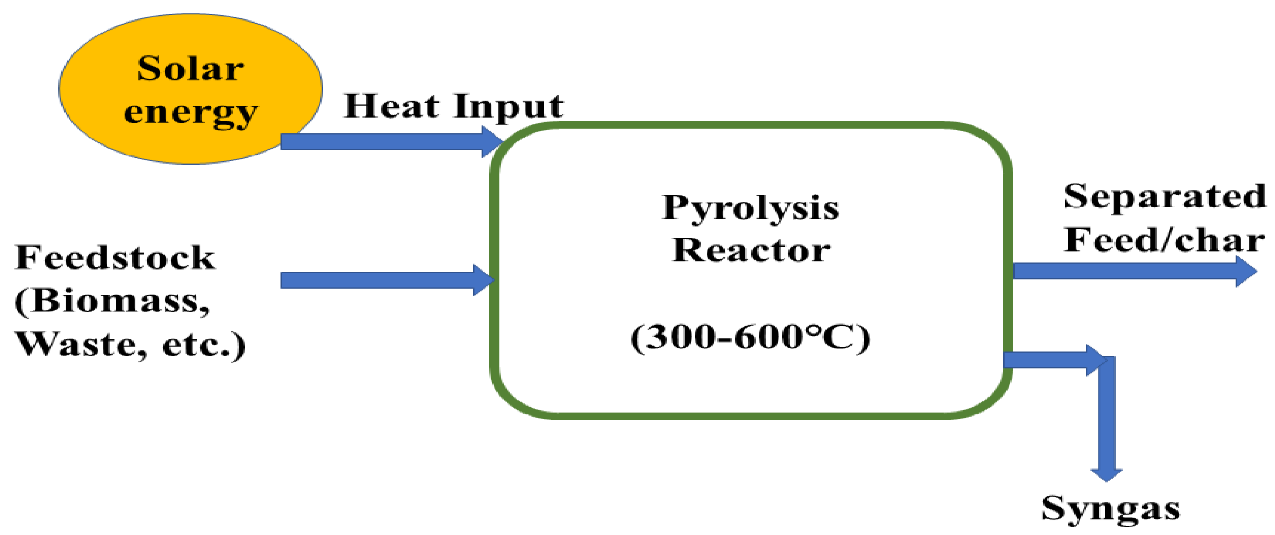
2.2.3. Solar Pyrolysis of Biomass

In a solar pyrolysis system, concentrated solar power supplies the thermal energy required for pyrolysis reactions of biomass. This concentrated solar thermal energy improves the quality of biomass energy by integrating solar energy in the pyrolysis products in the form of chemical energy and solar energy improves the chemical potentiality of biomass materials. Solar energy has not been used for conventional pyrolysis system, external energy is required in all conventional pyrolysis systems which are not a renewable source and this decreases the feasibility and sustainability and causes environmental drawbacks [88,91,92]. A schematic of solar assisted pyrolysis process is shown in Figure 3.
Rui Li et al. studied solar pyrolysis of agricultural and forestry bi-products such as peach pit, grape stalk, grape marc, and pine sawdust in a lab-scale solar reactor to investigate the syngas composition and pyrolysis product distribution at varying temperatures (800–2000 °C) and different heating rates (10–50 °C/s) [93]. They found the highest gas yield (63.5 wt%) with high H2/CO (>1) for 2000 °C temperature and 50 °C/s heating rate. M. Sanchez et al. experimented with slow pyrolysis in a linear Fresnel reflector (LFR) at 571 K temperature and 149 min of residence time and found a maximum of 40.8 wt% char was yielded from biomass feed [94]. Xiao He et al. studied solar-assisted molten salt pyrolysis of HulunBuir lignite to investigate the effect of different temperatures (500, 600, 700, and 800 °C) on produced gases and they found that solar-assisted molten salt pyrolysis produced more gas and less char than conventional pyrolysis systems [95]. They found the production of char decreased from 58.4% to 43.4% and gas production increased from 28.3% to 46.1% with their experimental setup. Besides, H2, CO, and CO2 yields increased by about 65.2%, 103.42%, and 60.43% at 800 °C temperature.

2.2.4. Molten Salt Pyrolysis

Molten salt pyrolysis is a promising method for thermochemical conversion of biomass to produce hydrogen-rich syngas; this process provides a liquid reaction environment and during pyrolysis molten salt can act as a solvent, catalyst, and thermal energy carrier [96]. Researchers have conducted experiments to investigate the advantages of molten salt mediums for biomass pyrolysis considering their rapid heating value and ability to improve catalytic and heat-transfer effects [97,98,99]. The thermal and chemical stability of molten salt are important factors in choosing a molten salt medium for biomass pyrolysis processes. Among different molten salts, researchers found alkali metal to be promising as a pyrolysis medium due to its potential as a catalyst [100]. Kuo Zeng et al. experimented with a novel reactor that was inserted in a molten salt (Li2CO3-Na2CO3-K2CO3) medium for fast pyrolysis of cotton stalks to compare with conventional pyrolysis at a temperature range (450–850 °C) [101]. Molten-salt pyrolysis produces more hydrogen-rich syngas than conventional pyrolysis at 750–850 °C. Roman Adinberg et al. experimented with a lab-scale reactor filled with sodium and potassium carbonate to investigate the kinetics of fast pyrolysis [102]. They also analyzed the characteristics of the heat transfer of cellulose particles introduced to molten salts at 1073–1188 K temperature and 100 K/s heating rate. There are some challenges in the molten-salt pyrolysis process that include the hardness of removing salt residues, as some salt’s hardness is rock-like and too hard to remove by a simple process such as hot water treatment. Other challenges include the high cost and corrosiveness of molten salts, which affects the decision to apply molten salt pyrolysis of biomass. Hongtao and Ning et al. studied molten salt pyrolysis in a stainless steel reactor where they used six kinds of biomass as feedstock materials and five different types of mixed molten salts as pyrolysis media; the operating conditions include 400–600 °C temperature and atmospheric pressure [96]. Their experimental results showed that when biomass material meets with molten salts quickly and homogeneously, the pyrolysis reaction temperature remains more scheduled.

2.2.5. Catalytic Pyrolysis of Biomass

Catalytic pyrolysis is a developing process for converting biomass into hydrogen-rich syngas following thermochemical processes. In catalytic pyrolysis, a catalyst is used to accelerate chemical reactions while the catalyst itself is not changed as the pyrolysis reaction progresses [103]. The optimum temperature for catalytic pyrolysis is 350–650 °C and various reactions take place during the whole process of catalytic pyrolysis such as cracking, reforming, water gas shift, PSA, and gas gasification [104]. Homogeneous (single-phase) and heterogenous (multi-phase) reactions have been used in catalytic pyrolysis for the last two decades. Transition metals, noble metals, and metal oxides are considered homogenous catalysts whereas acid and metal hydroxides are considered heterogenous catalysts. Researchers experimented with different heterogenous and homogenous catalysts to investigate their performance on catalytic pyrolysis. Heterogenous catalysts show high catalytic activity, longer durability, greater thermal stability, greater chemical stability, non-toxicity, an easy recovery process, and greater tolerance whereas homogenous catalysts are toxic, flammable, corrosive, and produce by-products and wastewater which require complex and expensive disposal procedures [105]. Siqian Cao et al. studied the in-situ steam catalytic cracking of coal pyrolysis in the presence of a Ni/Al2O3 catalyst with different Ni contents at 650 °C [106]. They analyzed the effects of the catalyst and found that when using the Ni/Al2O3 catalyst, water conversion increased and tar production decreased. Fangyuan Chen et al. prepared a Fe-Zn/Al2O3 nano-catalyst to investigate its effect on hydrogen production via catalytic pyrolysis process [107]. Their results revealed that 20% Fe/Al2O3 with Zn/Al ratio (1:1) showed the best performance on the basis of hydrogen production and coke formation on the catalyst’s surface. Jin Deng et al. experimented with different preparation methods of Fe-Co (bimetallic catalyst) such as co-impregnation and co-precipitation and performed catalytic pyrolysis of pine needle biomass at 0.1 MPa pressure and 700 °C temperature [108]. Their results showed that the Fe-Co catalyst prepared by co-impregnation exhibited better performance whereas the Fe-Co prepared by co-precipitation could reduce production of hydrogen. Jin deng et al., in their experiment, performed catalytic pyrolysis of herbal residues by Ni-Fe/Ca catalyst and investigated the effect of heating rate on the performance of catalyst in a fixed-bed reactor [109]. Their result revealed that using this catalyst tar and char conversion increased with impeding CO2 production and the H2 yield increased from 54.6 mL/g to 95.5 mL/g due to the catalytic effect of Ni-Fe/Ca. PR Bhoi et al. reported the progress of pyrolysis catalysts for improving hydrocarbon yield in bio-oil produced from biomass and they also explored several operating conditions such as temperature, heating rate, type of biomass, carrier gas, and hydrogen donor on the yield and properties of bio-oil [110]. Several noble catalysts such as zeolite-based catalysts, supported transition and noble metal catalysts, and metal oxide were revealed as preferable to obtain clean hydrocarbon-rich bio-oil.

2.2.6. Vacuum Pyrolysis of Biomass/Waste Material

Vacuum pyrolysis is an upgraded technology which is based on traditional pyrolysis and this technology has gathered much attention for its potential for hydrogen-rich syngas production from biomass or waste materials. Vacuum pyrolysis is performed in an oxygen-free vacuum environment at pressure of 0.5–50.0 kPa and temperature of 400–600 °C and there is no requirement of carrier gases (N2, He, Ar) to maintain the pyrolysis environment [111]. A vacuum pump evacuates the air inside the reactor and generates a pressure gradient in the reactor before the pyrolysis process to create an inert environment. The volatiles released during the pyrolysis of waste or biomass materials will immediately diffuse in the direction of the vacuum suction because volatiles must go from a higher pressure (inside the reactor) to a lower pressure (outside the reactor) to attain pressure equilibrium [112]. According to scientific reports, performing a pyrolysis reaction in a vacuum environment prevents the production of secondary pollutants such as nitrogen dioxides (NO2), ozone (O3), and peroxyacyl nitrates (PANs) when the pyrolysis volatiles are recovered and used again [113]. Implementing a vacuum pump to create a vacuum environment eliminates the requirement for carrier gas which needs additional thermal energy to be heated up, thus decreasing energy consumption and operational costs [114]. In the vacuum pyrolysis process, lower temperature is required for biomass to be pyrolyzed as vacuum condition generates negative pressure inside the reactor, which may assuage the boiling point of biomass materials [115]. There are also some limitations of vacuum pyrolysis such as the produced liquid oil having a high quantity of polycyclic macromolecular elements, which are created when volatiles are rapidly condensed and this prevents volatiles from further decomposing into smaller fragment compounds and reduces the quantity of combustible gases (H2, CO) produced. More research should be carried out to improve vacuum pyrolysis by implementing microwave heating, solar-assisted heating, and catalysts so that the production of hydrogen by vacuum pyrolysis can be increased.

2.2.7. Co-Pyrolysis

Co-pyrolysis is a thermochemical process where pyrolysis of multiple feedstock materials occurs simultaneously and this process improves system performance by utilizing synergistic effects, which are generated when two or more feedstock materials interact with each other [116]. Feedstock materials that are used for co-pyrolysis have very different chemical compositions and properties and this can also be seen in past research works. Li et al. studied co-pyrolysis for lignite and vacuum residue, which have different physical and chemical characteristics [117]. During co-pyrolysis, volatile substances which are unstable are liberated at lower temperatures, whereas volatile compounds that have greater stability are released at higher temperatures. In the case of co-pyrolysis, the combining ratio is an important affecting variable apart from the normal process variables of pyrolysis such as temperature, heating rate, cleaning gas flow rate, and particle shape. Karaeva et al. investigated co-pyrolysis of agricultural waste such as cow manure (CM) and stems of weed (SW) mixture for different mixing ratios (1:1, 2:1, 4:1) and the temperature range of 40 to 1000 °C [118]. Their result showed that a maximum produced hydrogen concentration of 21.17% is possible for CM/SW 4:1 at 550 °C temperature and 10 °C/min heating rate. Hafizur and PR Bhoi et al. carried out catalytic co-pyrolysis of pine and HDPE using a ZSM-5 catalyst in a double-column staged reactor and they analyzed the effects of temperature and pine/HDPE ratio on the selectivity of the hydrogen/carbon ratio [103]. Their result revealed that the yield of pyrolysis oil at a pine/HDPE ratio of 25/75 and at 500 °C was 3 times more than that of pine pyrolysis. Yiran et al. studied the co-pyrolysis of straw and polyethylene (PE) for hydrogen production with the presence of a Ni-La/Al2O3-CeO2-Bamboo charcoal (ACB) catalyst and they investigated the optimal combining ratio of straw and polyethylene and catalytic activity on hydrogen production [119]. Higher hydrogen production of 13.56 mmol/g is possible for a mixing ratio of 5:5 with the presence of Ni-La/ACB catalyst. Chao et al. studied the catalytic co-pyrolysis of waste paper (WP) and polyvinyl chloride (PVC) to produce hydrogen-rich synthesis gas [120]. The results of their experiment revealed that the maximum H2 yield (429 μmol·gcat−1·min−1) was achieved with 60 wt% PVC under 900 °C temperature and while a Fe/CeO2–Ca catalyst was used in optimum conditions, and a higher hydrogen yield (681.76 μmol·gcat−1·min−1) was obtained.

2.3. Gasification of Biomass

Hydrogen is an attractive candidate among other products such as heat, electricity, liquid fuels, solid fuels, and gaseous fuels, which are produced by gasification of biomass. Biomass gasification is a potential process through which hydrogen-rich syngas production can be possible. Alex Cheng et al. studied the gasification of α cellulose and other agricultural waste (biomass) with/without the presence of steam in a fluidized bed a 600–1000 °C temperature and from their investigation they found that a maximum of 29.5% hydrogen production was possible at an equivalent ratio of 0.2, temperature 1000 °C, and without steam conditions [121]. PR Bhoi et al. carried out co-gasification of switchgrass in a commercial-scale downdraft gasifier to measure and analyze syngas compositions, hot and cold gas efficiencies, tar content, and temperature effect at different co-gasification ratios (0%, 20%, and 40%) [122]. Their results indicated that maximum hot and cold gas efficiencies of 60.1% and 65.0% were achieved for a 40% co-gasification ratio. A schematic diagram is shown in Figure 4 to depict a biomass gasification system integrated with gas clean up unit.
Sahar and Seyed et al. established an artificial neural network-based model where a biomass gasification system was integrated with a water gas-shift process to produce hydrogen and they carried out this simulation to investigate the specific mass flow rate of the produced hydrogen for different biomass materials and at different operating conditions [123]. They proposed that biomass gasification integrated with the water gas-shift unit could be a potential thermochemical conversion process through which bio-hydrogen could be produced from suitable biomass materials. Tar content is considered as a major obstacle of biomass gasification and several research works have been carried out by researchers to overcome this obstacle. Sunil and PR Bhoi developed a tar-removing process to evaluate tar removal by cooling the syngas and using wood shavings as filter media [124]. They analyzed the tar removal efficiencies of wood shaving filters, wood shaving filters with a heat exchanger, and wood shaving filters with an oil bubbler and found 10%, 61%, and 97% efficiency respectively.

2.3.1. Gasification Integrated with Pyrolysis

Aishu and Hengda et al. studied a hydrogen-rich syngas production technology where they integrated the pyrolysis of sludge and the gasification of biomass and they also used a calcium-based additive for their integrated system [125]. Their output result revealed that adding MCA promoted steam reforming and water gas shift reaction with their integrated pyrolysis–gasification unit; a higher quantity of hydrogen production was made possible, which was approximately 268 mL/g. A gasification integrated pyrolysis system is shown with operating conditions in Figure 5.
Patrik Suhaj et al. experimented with a multistage biomass gasification system which included a pyrolysis stage and a split product gasification stage [126]. They integrated three reactors into one unit: an auger pyrolysis reactor, fixed-bed gasification reactor, and secondary catalytic reactor, and they found a high production of syngas (3.64 g·Nm−3) with a lower yield of tar (5.21 g·kg−1). Mahdi and Majid carried out an approach of an integrated pyrolysis–gasification unit for syngas production from algal biomass following different industrial operating conditions where the integrated unit performed three different processes including biomass drying, pyrolysis, and gasification [127]. In this study they investigated the impacts of different operating parameters such as air flow rate, gasifier pressure and temperature, sensitivity analysis on syngas (H2/CO), and end gas composition and they obtained optimum conditions for 600 °C temperature and 1 atm pressure.

2.3.2. Thermal Plasma Gasification

Thermal plasma gasification is an emerging thermochemical technology for hydrogen production by converting biomass and waste materials. The high temperature generated by plasma and highly reactive special components of it have the ability to intensify the gasification processes for which more than 90% decomposition of organic components is possible to produce more hydrogen-rich syngas. Besides, for achieving extreme high temperature in the gasification process, there is no need to use a catalyst to break down complex long-chain hydrocarbons. WenChao et al. studied a plasma-assisted steam gasification process to produce hydrogen from the mixture of wood sawdust and high-density polyethylene (HDPE) and investigated the effects of variable HDPE contents, input plasma power, and the steam-to-carbon (S/C) ratio [128]. Their result revealed that the maximum hydrogen (66.91%) yield was obtained for the input power 22 KW, HDPE ratio 80%, and steam-to-carbon ratio of 1. A high temperature plasma gasifier integrated with a reformer is shown in Figure 6.
Sikarwar et al. studied plasma assisted CO2-sorption-enhanced gasification to produce hydrogen-rich gas from organic waste stream [129]. They used three sorbents including CaO, Li4SiO4, and MgO, which were used in different conditions such as high, medium, and low temperature respectively. Shuming compared autothermal gasification and conventional gasification of cellulose to investigate the impact of heat from CaO carbonation on hydrogen production and their result showed that the highest hydrogen yield was obtained at 650 °C temperature in the autothermal gasification [130]. Simon et al. studied a microwave-induced plasma gasifier to produce hydrogen-rich syngas from biomass material and they used pure steam as the plasma operating gas [130]. Their result revealed that 98% biomass conversion efficiency and more than 60 vol% could be obtained for 6 KW input microwave power.

2.3.3. Torrefaction Pretreated Gasification of Biomass and Waste Material

Torrefaction is a thermochemical process typically performed at a lower temperature (200–350 °C), lower heating rate, and lower atmospheric pressure and the torrefaction reaction operates without the presence of oxygen. The torrefaction process is a promising pretreatment process of feedstock materials after which a higher conversion of feedstock (biomass, waste) is possible by gasification to produce a higher amount of hydrogen-rich syngas. Production of clean hydrogen can be accelerated significantly while torrefaction and gasification processes are integrated because the chemical and physical properties are increased due to torrefaction. Dharminder et al. studied the torrefaction of mixed food waste at different temperatures (230 °C, 260 °C, 290 °C) and they investigated the physio-chemical properties of torrefied food waste [131]. After this, they carried out gasification of the torrefied products and analyzed the composition of the produced syngas, amount of H2 production, and carbon conversion efficiency. Figure 7 shows a torrefaction integrated gasification system with operating conditions.
Kirsanovs et al. studied combined torrefaction and gasification process and stated that by applying biomass torrefaction it was possible to increase the total efficiency of biomass gasification [132]. Bach et al. examined the behaviors of raw and torrefied spruce wood during the gasification process and they also investigated gasification temperature and the effects of torrefaction and the steam-to-biomass ratio on biomass conversion by gasification [133]. Yuyang et al. studied torrefaction-pretreated chemical looping gasification of eucalyptus wood (EW) using different oxygen carriers (OC) to investigate the effects on hydrogen-rich syngas production and their result showed that gasification by using a NiFe2O4 oxygen carrier with torrefied eucalyptus could yield 27.5% more syngas than untreated EW over iron ore OC [134].

2.3.4. Catalytic Gasification of Biomass

Catalytic gasification of biomass and other materials is gaining extensive attention due to the emerging thermochemical conversion of biomass feedstocks into valuable hydrogen-rich syngas. Zakir Khan et al. studied the gasification of palm kernel shells (biomass material) in an integrated catalytic absorption steam gasifier at 675 °C temperature, biomass/catalyst (wt/wt) 0.1 [135]. At this operating condition they found 84.62 (vol%) H2 yield for 1.5 as the absorbent-to-biomass ratio, 2 as the steam-to-biomass ratio, and 0.1 as the catalyst-to-biomass ratio. Jianjun Hu et al. studied a catalytic conversion of pine wood (biomass material) with an activated char-supported Fe-Ni catalyst. Their result revealed that with increased catalytic activity the temperature of gasification increases, which assists in accelerating hydrogen production and from their experiment they found a maximum 1.97 H2/CO ratio at optimum conditions (750 °C temperature) [136]. Besides, they also investigated different biomass feedstock materials such as pine wood and cotton stalk for catalytic gasification and found pine wood as better on the basis of syngas production. Jingchun Yang et al. studied chemical looping catalytic gasification of algae biomass over LaNixFe1-xO3 perovskite oxygen carriers and the investigated effects on gasification performance due to rate of water injection, gasification temperature, and oxygen carrier-to-biomass mass ratio [137]. They achieved the highest hydrogen production at 850 °C temperature, 0.3 mL/min water injection rate, and 0.4 oxygen carrier-to-biomass ratio. Mahmood khan et al. studied catalytic gasification of Yuyang coal in a decoupled dual-loop gasifier and their experimental set-up consisted of a fluidized bed for gasification, a moving bed for reforming, and a particle-grading cyclone [138]. In their experiment, they investigated different process parameters such as reforming temperature, air equivalence ratio, and steam-to-coal ratio. Their result revealed that a maximum of 65.1 vol% hydrogen production and a minimum 5.8 g/Nm3 tar yield were possible at 850 °C temperature and 1.5 steam-to-coal ratio. Muhammad Irfan et al. studied the catalytic gasification of wet municipal solid waste (MSW) over HfO2-incorporated Ni-CaO catalyst for hydrogen-rich and tar-free synthesis gas production and they investigated the effects of different parameters such as gasification temperature, moisture content in feed material, catalyst-to-feed material (C/MSW) on hydrogen production, syngas yield, syngas composition, and tar content in produced gas [139]. Their experimental results revealed that hydrogen production increased from 212 mL/g to 442 mL/g in the presence of a Ni-CaO catalyst without a HfO2 supporter and the maximum yield of hydrogen, such 597 mL/g, was possible when HfO2 was used as a supporter in the Ni-CaO catalyst.

2.3.5. Sorption Enhanced Gasification of Biomass

Sorption-enhanced gasification of biomass is a novel technology for converting biomass and waste materials into hydrogen-rich syngas. This is an innovative process for producing high-purity H2 while decreasing CO2 emission in the environment. Researchers have studied this process by using various feedstocks, and different sorbents under different operating conditions to investigate the process efficiency to accelerate pure hydrogen yield capturing CO2. Christian et al. studied sorption enhanced gasification of cellulose and investigated the effects of CaO as a CO2 absorbent as well as a catalyst on hydrogen production [140]. Their result showed that the activity of CaO depends on gasification temperature and in the 550–700 °C temperature range CaO acts as an absorbent as well as a catalyst whereas at ≥750 °C temperature it acts only as a catalyst. They also found the optimum condition at temperature 650 °C and CaO-to-cellulose ratio ≥4. Hydrogen-rich (>70 vol%) gas can be produced directly by sorption-enhanced gasification without any assistance of WGS (water-gas shift) and CO2 separator [141]. Monica et al. investigated a sorption-enhanced gasification system of municipal solid waste (MSW) for hydrogen production to assess the techno-economic feasibility of the system and their result revealed that for applying sorption enhanced process hydrogen production was increased (48.7% H2 production efficiency) and CO2 emission was decreased [142]. They also analyzed economical parameters and found that when integrating sorption-enhanced processes, the operational cost was increased but the cost for CO2 removal was decreased. Xianyao studied sorption-enhanced steam gasification of bagasse char for hydrogen production where they used a bifunctional material, CeO2-modified CaO/Ca12Al14O33 [143]. When using this bifunctional material, they achieved a high hydrogen concentration (81.1 vol%) by promoting a water-gas shift and steam methane-reforming reactions and this material also facilitated CO2 capture. A schematic diagram depicting sorption-enhanced gasification system is shown in Figure 8.
Bin Li et al. developed a staged sorption-enhanced gasification system for hydrogen production from biomass where the system combined steam gasification (at a higher temperature) and steam reforming (at a lower temperature) where a CaO absorbent was used in the second stage [144]. Their result revealed that 99.7 vol% hydrogen concentration was possible while catalytic steam methane reforming was applied as the second stage. Salaudeen et al. studied the steam gasification of sawdust (biomass material) where they used eggshells as the CO2 sorbent for achieving hydrogen-rich gas with reducing CO2 emission [145]. They experimentally investigated the effects of gasification temperature, calcined eggshell-to-biomass ratio (CEBR), and steam-to-biomass ratio (SBR). Their result showed that the minimum amount of CO2 ( ~ 3.3%) and maximum amount of hydrogen ( ~ 78%) yield was possible CEBR of 1, SBR of 1.2, and temperature of 650 °C.

2.3.6. Autothermal Gasification of Biomass

Autothermal biomass gasification is a novel biomass conversion technology that produces hydrogen more energy efficiently by reducing gasification temperature and reducing CO2 emission. Yoon et al. studied autothermal gasification in a fixed-bed reactor to convert fine-grained woody biomass material into hydrogen, maintaining the operating conditions at 900 to 1020 K temperature and atmospheric pressure, steam-to-biomass ratio 0–0.6; they found 35% gasification efficiency [146]. Axel et al. examined autothermal gasification of biomass under variable solar irradiation to convert biomass thermochemically into hydrogen and they experimentally investigated the effects of injection rates of biomass, oxygen, and water on hydrogen-rich syngas production [147]. Shuming et al. stated that by applying autothermal biomass gasification, the production of gas can be increased and the emission of CO2 also can be reduced by reusing it [148]. They also found from their experiment that by using CaO, the hydrogen concentration was accelerated by 23.29% at 650 °C compared with the process where the reaction occurred at 750 °C without CaO. Xhang et al. studied biomass gasification in an autothermal gasifier and found energy and exergy efficiencies of 52.38–77.41% and 36.5–50.19% respectively [149]. Ren et al. performed auto-thermal supercritical water gasification of pig manure to produce pure hydrogen by applying an in-situ hydrogen separation unit [150]. Their result showed energy efficiency could reach 79.85%, which is 3.6–35.64% higher than traditional supercritical water gasification systems.

2.4. Thermal Plasma Technologies

2.4.1. Conventional Plasma Reforming

Plasma is a type of ionized gas and it can be used for hydrogen production as plasma reforming is thought to have the potential to produce hydrogen with the best efficiency. There are some challenges in the conventional hydrogen production technologies such as in SMR, POX, and ATR feed material conversion rate, and the yielded amount of hydrogen largely depends on the catalyst’s size, weight percentage, sintering, preparation, characterization, and activation. These challenges can be overcome by different operational modes developed with plasma technology [151,152]. This technology has greater potential to generate hydrogen from methane-carbon dioxide as methane consumption is lesser in it than in conventional reforming processes to utilize CO2 [153,154]. Temperature can be controlled by electricity and up to 2000 °C temperature can be achievable with this technology. Different feedstock materials such as methane or natural gas, ethanol, biomass waste, and other various types of fuels can be used in plasma-reforming technology [151,152,155]. Direct dissociation of hydrogen from methane is possible using this technology where the H2-rich gas is collected at the top side and carbon soot is collected at the bottom [156].
The plasma reforming process can be classified as thermal-plasma reforming and non-thermal-plasma reforming and this classification is based on electronic density, plasma state, and temperature. The temperature of the gas components is considered the main difference between thermal- and non-thermal plasma-reforming technology. A comparison is shown in Figure 9 where energy consumption rate is compared for thermal and non-thermal plasma processes for hydrogen production.
Thermal plasma-reforming technology is widely used where reforming at high temperature is required such as gasification of solid fuels, engine ignition systems, and lighting operations. Thermal plasma reforming is limited to some fuel due to electrode erosion caused for very high temperatures and this process has a high ionization degree and high dissociation degree. This technology has a wide range of applications which include powder metallurgy, synthesis of chemical components, surface finishing, and modification and other waste treatment suc as hospital waste and other industrial wastes. Insufficient control over this process and much amount of energy consumption are two main disadvantages of thermal plasma technology.
Non-thermal plasma reforming technology is more energy efficient than thermal plasma technology due to lower energy consumption for producing hydrogen and syngas. Keeping the gas temperature at room temperature, a high electron temperature can be achieved in non-thermal plasma technologies and in non-thermal plasma reactors, and electron temperature can be achieved up to 5000 K [157,158,159]. According to the reactor type, power consumption, flow rate, current, and discharging power there are mainly three types of reactorsL dielectric barrier discharge (DBD), corona discharge, and microwave discharge [160] and gliding arc discharge reactor [159]. Dynamic discharge is used to generate plasma in these processes. Additionally, other studied types of non-thermal plasma processes are- glow discharge, electron beam irradiation, spark discharge, micro frequency discharge, and micro hollow cathode discharge. These processes can be used for reforming different feed materials such as methane, diesel, and various types of biofuels [151,161,162,163].

2.4.2. Plasma Catalysis Process for Hydrogen Production

Combination of non-thermal plasma with catalysts is gaining popularity in CH4 and CO2 conversion to produce H2 and CO. Non-thermal plasma technology is a promising alternative to conventional thermal processes to enable heterogeneous catalysis to convert C1 molecules (C1 conversion is the selective catalytic transformation of one carbon molecule such as methane, carbon dioxide, carbon monoxide, or ethanol to generate valuable syngas). A wide range of chemical reactions and processes such as dry CO2 reforming, methane reforming, methanol reforming, and water-gas shift CO2 hydrogenation are widely used to activate and utilize CI molecules to produce CO and H2. Integration of NTP with a heterogenous catalyst has been proved as a potential energy-efficient process without the generation of unwanted by-products [164]. A Hybrid NTP–catalyst system enables the activation of C1 molecules (CH4, CO2) under relatively mild conditions compared with conventional thermal catalysis. In recent times, utilization of different catalysts in non-thermal plasma zones is frequently conducted to obtain an increment in conversion rate and improvement in hydrogen yield [165,166]. Mainly two different combinations of plasma-assisted catalysis are possible: post-plasma catalysis (Figure 10(c)) and in-plasma catalysis (Figure 10(d)). In the post-plasma catalyst, the end products coming out from the plasma go through the catalyst, which is located downstream of the plasma discharge [167]. In the in-plasma catalyst system, the catalyst is located inside the plasma-activated zone so that the catalyst can interconnect with all species which are produced in the plasma zone such as radicals, photons, and exciting species. As the catalyst is located inside the plasma zone, the plasma discharge is influenced by the catalyst and the catalyst is influenced by the plasma discharge and these influences improve the conversion of C1 molecules in the NPT-catalyst activated zone [168,169,170]. The conversion rate is depicted for four different processes: plasma, thermal catalysis, post-plasma catalysis, and in-plasma catalysis and among these techniques, the conversion rate in in-plasma catalysis is much higher than in the others. In the last two decades, many catalysts have received attention for use in dielectric barrier discharge reactors and among those, the Ni-based catalyst with the Al2O3 supporter is mostly used due to its low cost, easy process of preparation, and suitability inside the plasma discharge region. There are two main effects of integrating non-thermal plasma and catalyst-physical effects and chemical effects where improved energy efficiency occurs as physical effects and improved yield of targeted products are caused due to chemical effects. Different catalysts that are used in non-thermal plasma technologies have been studied and listed below in Table 1.

2.5. Steam Methane Reforming

Steam methane reforming is the most favorable and preferable technology which is used industrially for clean hydrogen production and it is also more economical than other developed technologies. A catalytic conversion occurs in this method where hydrocarbon and steam convert to hydrogen and carbon oxides and this method consists of syngas generation, water-gas shift, and purification of gas. Methane, natural gas, liquid hydrocarbon, and other gases (naphtha, ethane, etc.) that contain methane can be used to produce hydrogen by steam reforming method. Nickel is used as a reforming catalyst and to avoid poisoning of this catalyst; a desulfurization process can take place before the reforming process. The reforming reactors are operated at high temperatures, pressures greater than 3.5 MPa, and steam-to-carbon ratios equal to 3.5. Then, the gas mixture goes through the heat-recovery unit water-gas shift reactor where additional H2 is produced by the reaction of CO and steam, then the gases pass through a pressure-swing absorption (PSA) system from which 100% pure hydrogen is achieved. Different stages of steam methane reforming process are shown in Figure 11.
The main chemical reactions which take place in the steam reforming process are shown in the following equations.
C n H m + n H 2 O nCO + ( n + 1 2 m ) H 2  
CO + H2O → CO2 + H2
Steam methane reforming is a well-established method used for large-scale hydrogen production in industries all over the world. Steam and hydrocarbon gases react with each other in the presence of a nickel-based catalyst to produce hydrogen and when a PSA system is integrated with the reformer unit, pure H2 can be captured from the PSA system.
CO2 emission from the SMR unit is a major problem which may negate the benefits of a high amount of clean hydrogen production and high hydrogen-to-carbon ratio. For this purpose, capturing the emitted carbon content is badly needed to impede the greenhouse gas emission. Muhammad et al. proposed steam methane reforming (SMR) with a carbon capture system where the produced CO2 collected in the SMR hub is converted into formic acid by a CO2 electroreduction process [202]. Their proposed model minimized hydrogen production cost by eliminating the costs for CO2 transport and storage and their analysis revealed that a reduction of 4% to 9% hydrogen production cost was possible by using a 10 MW CO2 electrolyzer for formic acid generation. Zaira et al. proposed steam methane reforming (SMR) integrated with a CO2 capture-and-storage (CCS) system for hydrogen production to fulfill the demand in fuel cell electric vehicles from years of 2020–2050 [203]. Researchers are working to prepare a suitable catalyst for applying in SRM processes to improve the system by increasing hydrogen production and reducing carbon contents. Zhiliang et al. prepared different perovskites La0.7A0.3AlO3−δ (A=Ca, Ba, Ce, Mg, Zn, Sr) and investigated their role in Ni catalysts as supporters [204]. From their investigation it was revealed that Ni/La0.7Mg0.3AlO3δ showed an excellent catalytic activity and carbon deposition resistivity. Huchao et al. proposed a novel and impressive electrified steam methane-reforming process by accommodating renewable electricity [205]. They showed that their system can eliminate the limitations of conventional SRM processes such as CO2 emission, high cost, and high heat loss. Additionally, this integrated process increases the optimal thermal efficiency by 18% and electrical efficiency by 11.48% compared with conventional SRM and water electrolysis respectively. Chen et al. studied steam methane reforming (SMR) in a membrane reactor where heat was generated by molten salt and their purpose was to reduce carbon emission and accelerate hydrogen production rate [206]. They analyzed operating temperature, entropy generation, and hydrogen production rate and as result they found, for their proposed model, a 13.24% increase was possible in the hydrogen production rate.

2.6. Sorption-Enhanced Steam Methane Reforming (SESMR)

Sorption-Enhanced Steam Methane Reforming (SMR) is an emerging and attractive technology through which high-purity hydrogen can be obtained. SESMR is an intensified process where after performing conventional steam methane reforming, CO2 capture is performed by using a high-temperature sorbent material. After being saturated in the reformer, the sorbent goes through another reactor for calcination from which high-purity CO2 can be captured, which can be stored or supplied for utilizing in CO2 dry reforming processes. Different CO2 sorbents already have been tested in lab-scale experiments to obtain high-purity H2 and CO2. There are some characteristics which are considered to select a sorbent material such as long-period cyclic stability, favorable operating cost, ease regeneration of sorbents, thermal stability at high temperatures, and rich CO2 sorption ability. Figure 12 shows a sorption-enhanced steam methane reforming process where CaO was applied as sorbent material.
Sheu et al. studied SESMR in a fixed-bed reactor with a Ni/Al2O3 catalyst and CaO sorbent to investigate the effects of weight hourly space velocity (WHSV), temperature, and steam-to-carbon ratio on H2 and CO2 yield [207]. Nguyen et al. studied a SESMR process where their system consisted of a pretreatment process and heating, CO2 capture unit, a cyclic fluidized bed, reactor, compressor, and a PSA unit [208]. They found the energy efficiency to be 82.2% and a reduction of 12% in H2 production cost compared with conventional SMR processes. Shahid et al. studied SESMR in a packed-bed reactor where the used Ni catalyst and CaO, lithium zirconate (LZC), and hydrotalcite (HTC) sorbents [209]. They investigated the effects of sorbents on CH4 conversion and H2 purity and found that CH4 conversion was increased by 114%, 111%, and 67% compared with traditional SMR by using LZC, HTC, and CaO respectively. Gunawan et al. studied a SESMR process where they integrated concentrating solar power (CSP) to investigate solar-to-power conversion performance and they found nearly 41% efficiency for 800 K carbonation temperature and 1500 K calcination temperature [57]

2.7. Oxidative Steam Methane Reforming or Autothermal Reforming

The autothermal reforming process is a widely used technology for hydrogen production. It consists of SMR and POX processes. The operating pressure of an autothermal reaction is lower than that of the partial oxidation process. The heat generated in partial oxidation reactions is used in the catalytic region to operate the steam-reforming reactions and thus the reactions in SMR occur very fast. By using autothermal reforming technology, a considerable amount of thermal energy can be saved compared with conventional steam methane-reforming technology for producing hydrogen. The operating pressure can be up to 70 bars and the temperature remains at 1000–1200 °C in the autothermal reactor.
Reaction in the combustion chamber occurs following Equation (1) [210].
CH 4 + 3 2 O 2 CO + 2 H 2 O Δ H = 519   Kj / mol
Steam reforming reaction follows Equation (2) [211].
CH 4 + H 2 O CO + 3 H 2 Δ H = 206   Kj / mol
Water gas shift reaction follows Equation (3) [212].
CO + H 2 O CO 2 + H 2 Δ H = 206   Kj / mol
Autothermal reforming (ATR) is more favorable than partial oxidation processes such that there is no need to supply external heat and a large quantity of hydrogen can be produced in this process with rapid starting and stopping. Figure 13 shows a autothermal reforming process for hydrogen production. In this process, combustion can be controlled by controlling the temperature and the temperature can be controlled by the oxygen-to-fuel ratio and steam-to-carbon ratio [213,214,215]. Cherif et al. studied autothermal reforming of methane and steam with Ni/Al2O3 and Pt/Al2O3 catalysts where they compared two processes with these catalysts [216]. In the first process they modeled the catalysts as continuous layers, whereas in the second model they organized them as a patterned layer and they found 3.6% more hydrogen yield for the second model. In autothermal reforming process, pure oxygen is needed for which an air-separation unit (ASU) by which pure oxygen can be obtained is required and the separated ATR and ASU units increase the costs of a plant. Kim et al. proposed a model of ATR which is integrated with ASU and liquefied natural gas (LNG) regasification so that hydrogen production was possible by utilizing the cold energy obtained from LNG regasification [217]. They found hydrogen purity of 99.2%, a 18.6% reduction in exergy destruction, and overall 25.4% more exergy efficiency than traditional SMR processes.

2.8. CO2 Dry Reforming of Methane (CH4)

Carbon dioxide reforming of methane has received much attention in recent years due to its promising potential for methane conversion. This process is beneficial to the environment because two greenhouse gases can be utilized to produce valuable syngas in this process [218,219]. The use of non-thermal plasma reactors potentially permits dry reforming of CO2 as NTP can be operated at lower temperatures and less material and energy are required [220].
CO2 + CH4 → 2CO + 2H2        ∆H = 247 kJ/mol
The C-O bond in CO2 and the C-H bond in CH4 are much more stable and due to this, it is not an easy task to coactivate these bonds [221,222,223,224]. To coactivate these bonds, DRM reactions require high temperatures (nearly 800 °C) and many experiments have been carried out by researchers for high-temperature dry methane-reforming technology whereas for DRM relatively fewer experiments have been performed for the development of the catalyst which can work at a lower temperature (below 600 °C) [225,226,227,228]. For operating at such a high temperature, the system has a high cost, and causes coke formation and nickel sintering, which can cause catalyst deactivation. To solve these problems, researchers are focusing on a hybrid system of non-thermal plasma and catalyst, which can be a potential solution. A list of catalyst that were studied for CO2 dry reforming process are listed in Table 2. Seigo et al. [229] investigated dry methane reforming of a non-thermal plasma bed at a lower temperature in the presence of a Ni-based Al2O3-supported catalyst. Researchers are also working to develop catalysts that can be good alternatives to Ni-based catalysts, as there are some existing disadvantages in Ni-based catalysts at lower temperatures for DRM processes, e.g., low activity of Ni-based catalysts [230], generation of NiO shells deactivating the catalysts by covering Ni particles, [231,232] and deactivation of the catalyst due to CO disproportionation and direct decomposition of methane [225,233]. Jan Kehres et al. [234] performed dry methane reforming at a temperature range of 823–1023K where the molar ratio of gaseous CO2 to CH4 was 3:1 and Ru/MgAl2O4 was used as a catalyst.

2.9. Chemical Looping Combustion (CLC)

Chemical looping combustion is an attractive potential technology to produce pure hydrogen and power with carbon dioxide capture and in recent times it has achieved much attraction for its potential of using gaseous fuel. As the amount of reserved coal is sufficient for power generation, the development of proper technology to utilize coal is required and chemical looping combustion technology can be a potential solution for this. For this reason, studies and experiments have been carried out to improve CLC technology by researchers in different developed countries. Two systems of CLC technology have been developed: two-reactor systems (Figure 14a) for only power generation and three-reactor systems (Figure 14b) in which hydrogen and power can be generated simultaneously. In two-reactor systems, there are two reactors: a fuel reactor and an air reactor. Oxides of different materials such as manganese, magnesium, copper, and iron can be used as metal oxides in a chemical looping combustion unit. In the fuel reactor, the oxygen carrier (OC) and coal are fed directly and fuel combustion and reduction of OC take place. A CO2-rich stream exits from the fuel reactor and a N2-rich stream exits from the air reactor. The other type is a three-reactor system where a steam reactor is integrated into the middle of the other two reactors (fuel reactor and air reactor).
As metal oxide, ferric oxide (Fe2O3) is normally used in three reactors CLC systems because it has several reducing states like Fe, FeO, Fe3O4, etc. Combustion takes place with the presence of coal and CO2/steam in the fuel reactor and oxygen carrier Fe2O3 is partially reduced to Fe/FeO and then it goes through the steam reactor where complete reduction of OC Fe/FeO occurs. The completely reduced OC is re-oxidized in the air reactor with the presence of air. The available literature depicts that normally gaseous fuels are used in CLC technologies for the co-generation of hydrogen and power [254]. A CLC technology-based power plant’s output shows the improvement in synthesis gas production, power generation, carbon dioxide capture, and production of hydrogen with low cost [255,256]. Domenico Sanfilippo developed a new process for hydrogen production where H2 is produced by water splitting and this split occurs due to oxidation of iron oxide, which is carried out by the chemical looping combustion (CLC) process [257]. He also showed that his developed process is more environmentally friendly and energy efficient than the conventional processes because he ensured the management of heat exchange more efficiently. Alam and Sumana carried studies to obtain a suitable combination of OC with different inert supports to evaluate a CLC-integrated sorption-enhanced steam methane reformer (CLC-SESMR)’s performance [258]. Hu and Chen presented a study on methane-fueled CLC to analyze the effects of different promoters on methane conversion and hydrogen production and the result of the study showed that Ni-promoted OCs accelerate methane conversion and hydrogen yield, Co dopant improves the oxygen capacity, and Cu dopant impedes the reduction of iron-based OCs [259]

2.10. Chemical-Looping Steam Methane Reforming

Chemical-looping steam methane reforming (CL-SMR) is a thermochemical conversion process which can produce high-quality syngas and clean hydrogen. Lower heat energy is required for the reaction in this process and the reaction may take place at a lower temperature than conventional steam methane-reforming technologies. The reaction kinetics of oxygen carriers are always coupled with significant carbon deposition caused by methane catalytic cracking, which can cause a quick breakdown of oxygen carriers and the formation of low-grade hydrogen. A suitable selection of the oxygen carrier (OC) is required to overcome this limitation and when a favorable OC is selected, a higher amount of clean H2 and syngas can be produced from the CL-SMR system. Researchers have carried out experiments with different OCs to investigate their influences on the chemical reaction of CL-SMR and hydrogen production rate. Among those OC materials, researchers have been working with perovskite materials in recent years to analyze their effects. Xianglei et al. studied a CL-SMR process to investigate the effect of perovskite oxygen carrier LaMn1−xAlxO3+δ (x = 0, 0.1, 0.3, 0.5, 0.7) and, according to their result, LaMn0.5Al0.5O3+δ showed the best performance with a production of 3.32 mmol·g−1 and 1.70 mmol·g−1 for H2 and CO respectively [260]. Zheng et al. studied CL-SMR for hydrogen and syngas production where they used perovskite material as the oxygen carrier and their result revealed that La0.85MnCu0.15O3 and La0.8MnCu0.2O3 showed the best performance with high H2/CO (1.92–2.1) among the other OC configurations they studied [261]. Table 3 shows a list of oxygen carriers that are recently used in chemical looping steam methane reforming processes.

2.11. Sorption Enhanced Chemical Looping Steam Reforming

Sorption-enhanced chemical-looping steam reforming is a novel technology for producing pure hydrogen and this process is the integration of SESR (sorption-enhanced steam reforming) and CLSR (chemical-looping steam reforming). This methodology was experimentally performed at atmospheric pressure in a fixed-bed bench-scale flow unit which consists of a reactor, product analyzer, a furnace, three thermocouples for monitoring the temperature attached to the bed, and an HPLC pump [272]. The thermocouples are controlled independently with several temperature regions and heated by the furnace. In this method, an oxygen carrier catalyst is used that carries O2 from the air to the fuel without any touch of air and fuel. The oxygen carrier is prepared following different processes such as wet impregnation, co-precipitation, filtration, washing, drying (at 100 °C), and calcination [273]. A SE-CLSR system consists of three types of reactors that have different operations including a calcination reactor for regenerating the sorbent, a reforming reactor for oxidation of the feedstock material (methane), and an oxidation reactor for oxidation of oxygen carrier. In the reforming reactor, with the presence of oxygen methane is partially oxidized where oxygen is continuously carried by NiO OC (oxygen carrier) [274].
Two moving-bed reactors (Figure 15a) or one fixed-bed reactor (Figure 15b) system are used in the SE-CLSR system. Steam reforming, water gas shift, oxidization, capture of CO2 through nickel oxide-based oxygen carrier, and Cao sorbent were used to produce hydrogen continuously in moving bed reactors. On the other hand, in the alternative fixed-bed reactor H2 production, air oxidation, nitrogen sweeping, and oxygen carrier reduction take place stepwise. The effects of temperature and steam-to-carbon ratio were analyzed in the “two moving-bed reactors” experiment and the production of pure H2 increased with the increasing temperature and steam-to-carbon ratio. At the stoichiometric condition when the steam-to-carbon ratio equaled 1, the purity of H2 was 80%, and 90% pure hydrogen could be achieved if the stoichiometric condition was 1.5–3 times the previous condition and at 500–600 °C initial temperature in the autothermal process [275]. In the case of an alternating fixed-bed reactor, the highest hydrogen production was possible under the conditions when the calcium-to-nickel molar ratio was 2–3 [276].

3. Recent Carbon Capture and Greenhouse Gas Utilization Routes in Hydrogen Production Technologies

Developing an efficient purification process to obtain clean hydrogen in an environment-friendly way is the main challenge in hydrogen-production technologies. In traditional hydrogen-production technologies, the produced syngas is first cooled to the required temperature of absorption unit after passing out from the WGS reactor and then this cooled gas passes through CO2 absorption unit where CO2 is captured and removed, and then the gas (CO + H2) goes through an additional purification unit to yield pure hydrogen by removing CO [277]. A conventional hydrogen purification system is shown in Figure 16 which is wide used to produce pure hydrogen from hydrogen-rich syngas.
In recent years, researchers have developed the elevated-temperature pressure-swing adsorption (ET-PSA) method, which is much more energy efficient than conventional hydrogen purification processes as it operates at elevated temperatures of 200–450 °C, eliminating the precooling and reheating processes of syngas [278]. Zhu et al. designed ET-PSA integrated an IGCC (Integrated gasification combined cycle) plant to investigate the specific primary energy consumption for CO2 avoided (SPECCA) and also analyzed the effects of purge and rinse steps on energy consumption of ET-PSA processes [279]. Elimination of additional WGS, CO2 absorption and CO separation unit is possible when WGS catalysts and CO2 absorbents are applied in a single ET-PSA unit (Figure 17). Several chemical absorbent materials were studied such as sodium-based materials [280], lithium-based materials [281], and CaO [282], which have good CO2 absorption ability at elevated temperatures but their performances are limited due to their slow kinetics, weak reversibility, and high energy consumption for regeneration. Physical absorbents such as alumina [283], zeolites [284], and activated carbon [285] are not effective as CO2 absorbents due to their weakness and sensitivity to temperature. Researchers carried out several studies to enhance their selectivity and to improve their interaction ability with CO2 through chemical modification on their surface, but at elevated temperatures their performance as CO2 absorbents is still poor. Researchers have carried out experiments for the last three decades on LDOs derived from layered-double hydroxides (LDHs) and they found good applicability of LDOs due to having a favorable balance between CO2 capacity and reversibility [286] and they can receive up to 60–70% CO2 of its total capacity within ten minutes, which shows its suitability for use in pressure-swing adsorption [287]. As with the presence of H2O, the absorption ability of LDOs increases, so for impurities such as H2S and H2O there is no negative impact on LDOs performance [288]. Moreover, LDOs exhibit very low degradation after thousands of cycles of adsorption [289,290]. For having these extraordinary properties LDOs are considered as suitable for ET-PSA processes.
In general, different post-combustion carbon capture technologies are used in hydrogen production technologies in different developed countries. Among these carbon capture technologies are dry adsorption, wet adsorption, cryogenics, and membrane-based technologies. Dry adsorption is advantageous for application due to its simple mechanism, ease of operation, high energy efficiency, and environmentally friendly operation whereas the main disadvantages of this system include poor separation efficiency and unsuitability for the large volume of combusted emissions [291,292]. Wet absorption is efficient for treating massive quantities of combusted emissions and is highly beneficial for adjusting the concentration of CO2; however, it consumes a significant amount of energy to regenerate the absorbent. Other disadvantages of wet absorption include the requirement of heated absorbents, material erosion, and sluggish solid–gas reactions [293,294,295]. Cryogenics is a feasible process due to its lower investment costs and great reliability but ultimately it is not favorable due to its high energy consumption [296,297]. Membrane-based carbon capture is a recently developed technology whose advantages include its simple mechanism, ease of operation, and low energy demand whereas its disadvantages include low durability, its expensive module, and unsuitability for large-volume combusted emissions [298,299].

4. Comparison of Different Thermochemical H2 Production Technologies

The growth of different thermochemical conversion technologies for hydrogen generation is evident. According to chemical reaction, temperature range, cost, additives, catalytic effect, system size, stability, energy consumption, produced gas composition, emission, and feed conversion efficiency, a thermochemical conversion process is qualified for hydrogen production. There are both advantages and disadvantages in these technologies according to these parameters. Table 4 shows comparison among some thermochemical processes in terms of operating conditions, advantages, limitations and efficiency.
Falter et al. investigated the hydrogen production cost and environmental effects of hydrogen production technology in the United States and found that by applying the solar thermochemical conversion process, the costs would be 2.1–3.2 EUR/kg (2.4–3.6 USD/kg), which is half of the cost if the conventional steam methane-reforming process were applied [300]. They also stated that reduction of greenhouse gas emissions was possible by approximately 90%. Milani reviewed hydrogen production routes integrated with renewable sources and they categorized commercial hydrogen production paths in Australia into two developed ways: electrolysis powered by renewable and steam methane reforming or coal gasification integrated with carbon capture and sequestration [301]. It was also reported that in Australia hydrogen production cost was lowered by applying steam methane reforming and black-coal gasification. Youjun et al. proposed a novel solar-driven supercritical water gasification process for hydrogen production in China through which it was possible to obtain a high-efficiency solar thermal decomposition of water and biomass [302]. They also performed cost and sensitivity analysis for their system, and by comparing with other hydrogen production technologies they proposed their method as promising and competitive in the commercial market. By analyzing and considering the parameters, advantages, disadvantages, suitability with operating conditions, emissions, cost, system size, and sustainability of a process, it should be implemented for producing hydrogen industrially.

5. Future Potential

Clean hydrogen production through thermochemical pathways has more potential than other approaches as an unlimited amount of biomass products, waste materials, and agricultural residues are available around the environment. It is also possible to decrease greenhouse gas emissions by utilizing greenhouse gases (CO2, CH4) through thermochemical conversion. Thus, clean energy and a clean environment are possible through implementing thermochemical processes with suitable pathways. Payam et al. analyzed green hydrogen production technologies in Denmark and found scale-up effects and technology developments can drop hydrogen prices below 2 €/Kg [303]. They also suggested regulating carbon content to change grey hydrogen to green. Ramchandra forcasted hydrogen demand across electricity and transport sectors in West Africa until 2040 and his analysis showed the electricity demand at 2934 GWh and hydrogen demand at 0.117 Mt [304]. He also assessed different electrolytes and water requirements. Growth of the hydrogen production rate by thermochemical processes is possible if these can be integrated with a process-favorable catalytic system. Different thermochemical pathways were conducted by lab-based experiments, but for large-scale hydrogen production, a continuous process is needed which should be environment-friendly, cost-effective, and techno-economically stable for continuous hydrogen production. At present, biomass and hydrocarbons are the major sources of feed that are used for producing hydrogen, but there is a huge amount of waste products that can be utilized to produce energy and to make the environment clean. Although renewable-assisted (solar, wind) methods are more costly, the excess energy which is produced by solar panels or wind turbines during the period of low energy demand can be used for hydrogen production. Gasification and pyrolysis of biomass can be improved by integration with small-size powerplants, which can be installed near biomass generation units and the waste heat produced from the plant can also be utilized in several applications. Carbonaceous ash is produced during gasification and pyrolysis for agriculture purposes for the treatment of soil to accommodate the carbon and mineral deficiencies. Steam reforming is known as the most efficient process among other thermochemical processes due to its continuous development for hydrogen production. The steam-reforming process can further be improved by using different suitable catalysts which promote reactions at lower temperatures and accelerate the growth of the hydrogen production rate. Chemical-looping processes can be integrated with steam reforming to accelerate the production of hydrogen-rich syngas. Moreover, for further improvement, CO2-sorbent additives can be integrated to obtain clean hydrogen without emission of CO2. Novel absorbents with higher CO2 absorption capacity need to be prepared for commercial applications in hydrogen production technologies. Thermal plasma technologies can generate extremely high temperatures which can grow the feedstock conversion rate but are complex in design, so more research should be conducted on lab scale to minimize the complexity of plasma systems.

6. Conclusions

Technologies for hydrogen production are being developed and further promoted as it is clear to all that the demand for hydrogen is increasing in several applications. Considering this, different hydrogen production methods through which renewable sources can be properly implemented are discussed. Among other hydrogen production technologies, thermochemical is in the highest ranking as it is most favorable due to its cost-effectiveness, ease of production pathways, and renewable sources which may cope with thermochemical processes easily compared with other technologies (biolysis, photolysis, electro-photolysis, etc.). In this review, recent advances in thermochemical technologies for hydrogen-rich syngas production were summarized. The latest catalysts and absorbent materials were reviewed to discuss their performances in different thermochemical feed conversion processes and different emerging carbon-capture technologies were also reviewed. Recent developments in steam-reforming technologies will continue their dominancy in the next years due to their feedstock conversion efficiency and high rate of hydrogen production. The sorption-enhanced steam-reforming and chemical-looping steam-reforming processes are attracting more attention because high productivity of clean hydrogen and CO2 removal through in-situ processes is possible by applying these advanced thermochemical technologies. Concentrated-solar power-assisted reforming technologies are also emerging among other hydrogen production processes. Techno-economic improvement, suitable energy production cost, minimized emission, less energy usage, sustainability, and growing environment-friendly pathways are the main influencers of hydrogen infrastructure. Besides, utilization of renewable energy suppliers (solar) and renewable sources of feed (biomass, waste, agricultural residues) in proper methods for hydrogen production can enhance the sustainability of the environment and can decarbonize the energy sector as well.

Funding

This research received no external funding.

Conflicts of Interest

The authors declare no conflict of interest.

Abbreviations

ATRAutothermal Reforming
CLCChemical Looping Combustion
CLSRChemical Looping Steam Reforming
DBDDielectric Barrier Discharge
ET-PSAElevated Temperature Pressure Swing Adsorption
GADGliding Arc Discharge
HDPEHigh-Density Polyethylene
LDHLayered Double Hydroxide
LDOLayered Double Oxide
MDMicrowave Discharge
NPTNon-Thermal Plasma
PASRPlasma Assisted Steam Reforming
POXPartial Oxidation
PSAPressure-Swing Adsorption
SDSpark Discharge
SECLSRSorption-Enhanced Chemical Looping Steam Reforming
SESMRSorption-Enhanced Steam Methane Reforming
SMR Steam Methane Reforming
WGSWater Gas Shift

References

  1. United Nations Department for Economic and Social Affairs. World Population Prospects 2019: Highlights; United Nations Department for Economic and Social Affairs: New York, NY, USA, 2019; Volume 11, p. 125. [Google Scholar]
  2. Zhang, J. Techno-Economic Analysis and Optimization of Distributed Energy Systems. Ph.D. Thesis, Mississippi State University, Stackwelly, MS, USA, 2018. [Google Scholar]
  3. Alanne, K.; Cao, S. An overview of the concept and technology of ubiquitous energy. Appl. Energy 2019, 238, 284–302. [Google Scholar] [CrossRef]
  4. Helm, D. The future of fossil fuels—Is it the end? Oxf. Rev. Econ. Policy 2016, 32, 191–205. [Google Scholar] [CrossRef]
  5. Michaelides, E.E. A New Model for the Lifetime of Fossil Fuel Resources. Nat. Resour. Res. 2016, 26, 161–175. [Google Scholar] [CrossRef]
  6. Dicks, A.L.; Rand, D.A.J. Fuel Cell Systems Explained; John Wiley & Sons: Hoboken, NJ, USA, 2018. [Google Scholar]
  7. Tian, Y. Grid-Connected Energy Storage Systems: Benefits, Planning and Operation. Ph.D. Thesis, Michigan State University, East Lansing, MI, USA, 2018. [Google Scholar]
  8. Jacobson, M.Z. Control of fossil-fuel particulate black carbon and organic matter, possibly the most effective method of slowing global warming. J. Geophys. Res. Atmos. 2002, 107, ACH 16-1–ACH 16-22. [Google Scholar] [CrossRef]
  9. Abbasi, T.; Abbasi, S.A. Decarbonization of fossil fuels as a strategy to control global warming. Renew. Sustain. Energy Rev. 2011, 15, 1828–1834. [Google Scholar] [CrossRef]
  10. Wigley, T.M.L. Could reducing fossil-fuel emissions cause global warming? Nature 1991, 349, 503–506. [Google Scholar] [CrossRef]
  11. Yin, Y.; Bowman, K.; Bloom, A.A.; Worden, J. Detection of fossil fuel emission trends in the presence of natural carbon cycle variability. Environ. Res. Lett. 2019, 14, 084050. [Google Scholar] [CrossRef]
  12. Abbasi, T.; Premalatha, M.; Abbasi, S.A. The return to renewables: Will it help in global warming control? Renew. Sustain. Energy Rev. 2011, 15, 891–894. [Google Scholar] [CrossRef]
  13. Winter, R.A. Innovation and the dynamics of global warming. J. Environ. Econ. Manag. 2014, 68, 124–140. [Google Scholar] [CrossRef]
  14. Dincer, I.; Acar, C. A review on clean energy solutions for better sustainability. Int. J. Energy Res. 2015, 39, 585–606. [Google Scholar] [CrossRef]
  15. Olabi, A.G. Energy quadrilemma and the future of renewable energy. Energy 2016, 108, 1–6. [Google Scholar] [CrossRef]
  16. Gielen, D.; Boshell, F.; Saygin, D.; Bazilian, M.D.; Wagner, N.; Gorini, R. The role of renewable energy in the global energy transformation. Energy Strategy Rev. 2019, 24, 38–50. [Google Scholar] [CrossRef]
  17. Panwar, N.L.; Kaushik, S.C.; Kothari, S. Role of renewable energy sources in environmental protection: A review. Renew. Sustain. Energy Rev. 2011, 15, 1513–1524. [Google Scholar] [CrossRef]
  18. Moriarty, P.; Honnery, D. What is the global potential for renewable energy? Renew. Sustain. Energy Rev. 2012, 16, 244–252. [Google Scholar] [CrossRef]
  19. Chang, J.; Leung, D.Y.C.; Wu, C.Z.; Yuan, Z.H. A review on the energy production, consumption, and prospect of renewable energy in China. Renew. Sustain. Energy Rev. 2003, 7, 453–468. [Google Scholar] [CrossRef]
  20. Elliott, D. Renewable Energy in the UK: Past, Present and Future; Springer: Berlin/Heidelberg, Germany, 2019. [Google Scholar]
  21. Frey, G.W.; Linke, D.M. Hydropower as a renewable and sustainable energy resource meeting global energy challenges in a reasonable way. Energy Policy 2002, 30, 1261–1265. [Google Scholar] [CrossRef]
  22. Batel, S. Research on the social acceptance of renewable energy technologies: Past, present and future. Energy Res. Soc. Sci. 2020, 68, 101544. [Google Scholar] [CrossRef]
  23. Stram, B.N. Key challenges to expanding renewable energy. Energy Policy 2016, 96, 728–734. [Google Scholar] [CrossRef]
  24. Sen, S.; Ganguly, S.; Das, A.; Sen, J.; Dey, S. Renewable energy scenario in India: Opportunities and challenges. J. Afr. Earth Sci. 2016, 122, 25–31. [Google Scholar] [CrossRef]
  25. Eissa, M.M. Challenges and novel solution for wide-area protection due to renewable sources integration into smart grid: An extensive review. IET Renew. Power Gener. 2018, 12, 1843–1853. [Google Scholar] [CrossRef]
  26. Murdoch University Research Repository. Fast Track to Renewables: Low Emission Electricity for South West Australia by 2030. Available online: https://researchrepository.murdoch.edu.au/id/eprint/36358/ (accessed on 29 June 2022).
  27. Beshr, E.H.; Abdelghany, H.; Eteiba, M. Novel optimization technique of isolated microgrid with hydrogen energy storage. PLoS ONE 2018, 13, e0193224. [Google Scholar] [CrossRef]
  28. Colbertaldo, P.; Agustin, S.B.; Campanari, S.; Brouwer, J. Impact of hydrogen energy storage on California electric power system: Towards 100% renewable electricity. Int. J. Hydrogen Energy 2019, 44, 9558–9576. [Google Scholar] [CrossRef]
  29. Ahmad, M.S.; Ali, M.S.; Rahim, N.A. Hydrogen energy vision 2060, Hydrogen as energy Carrier in Malaysian primary energy mix—Developing P2G case. Energy Strategy Rev. 2021, 35, 100632. [Google Scholar] [CrossRef]
  30. Shi, L.; Qi, S.; Qu, J.; Che, T.; Yi, C.; Yang, B. Integration of hydrogenation and dehydrogenation based on dibenzyltoluene as liquid organic hydrogen energy carrier. Int. J. Hydrogen Energy 2019, 44, 5345–5354. [Google Scholar] [CrossRef]
  31. Abe, J.O.; Popoola, A.P.I.; Ajenifuja, E.; Popoola, O.M. Hydrogen energy, economy and storage: Review and recommendation. Int. J. Hydrogen Energy 2019, 44, 15072–15086. [Google Scholar] [CrossRef]
  32. Baroutaji, A.; Wilberforce, T.; Ramadan, M.; Olabi, A.G. Comprehensive investigation on hydrogen and fuel cell technology in the aviation and aerospace sectors. Renew. Sustain. Energy Rev. 2019, 106, 31–40. [Google Scholar] [CrossRef]
  33. Manoharan, Y.; Hosseini, S.E.; Butler, B.; Alzhahrani, H.; Senior, B.T.F.; Ashuri, T.; Krohn, J. Hydrogen Fuel Cell Vehicles; Current Status and Future Prospect. Appl. Sci. 2019, 9, 2296. [Google Scholar] [CrossRef]
  34. Sorgulu, F.; Dincer, I. A renewable source based hydrogen energy system for residential applications. Int. J. Hydrogen Energy 2018, 43, 5842–5851. [Google Scholar] [CrossRef]
  35. Yue, M.; Lambert, H.; Pahon, E.; Roche, R.; Jemei, S.; Hissel, D. Hydrogen energy systems: A critical review of technologies, applications, trends and challenges. Renew. Sustain. Energy Rev. 2021, 146, 111180. [Google Scholar] [CrossRef]
  36. Ozturk, M.; Dincer, I. Life cycle assessment of hydrogen-based electricity generation in place of conventional fuels for residential buildings. Int. J. Hydrogen Energy 2020, 45, 26536–26544. [Google Scholar] [CrossRef]
  37. Jahangiri, M.; Soulouknga, M.H.; Bardei, F.K.; Shamsabadi, A.A.; Akinlabi, E.T.; Sichilalu, S.M. Techno-econo-environmental optimal operation of grid-wind-solar electricity generation with hydrogen storage system for domestic scale, case study in Chad. Int. J. Hydrogen Energy 2019, 44, 28613–28628. [Google Scholar] [CrossRef]
  38. Minutillo, M.; Perna, A.; Sorce, A. Combined hydrogen, heat and electricity generation via biogas reforming: Energy and economic assessments. Int. J. Hydrogen Energy 2019, 44, 23880–23898. [Google Scholar] [CrossRef]
  39. Ayodele, T.R.; Alao, M.A.; Ogunjuyigbe, A.S.O.; Munda, J.L. Electricity generation prospective of hydrogen derived from biogas using food waste in south-western Nigeria. Biomass Bioenergy 2019, 127, 105291. [Google Scholar] [CrossRef]
  40. Endo, N.; Shimoda, E.; Goshome, K.; Yamane, T.; Nozu, T.; Maeda, T. Simulation of design and operation of hydrogen energy utilization system for a zero emission building. Int. J. Hydrogen Energy 2019, 44, 7118–7124. [Google Scholar] [CrossRef]
  41. Endo, N.; Shimoda, E.; Goshome, K.; Yamane, T.; Nozu, T.; Maeda, T. Construction and operation of hydrogen energy utilization system for a zero emission building. Int. J. Hydrogen Energy 2019, 44, 14596–14604. [Google Scholar] [CrossRef]
  42. Gao, J.; Xing, S.; Tian, G.; Ma, C.; Zhao, M.; Jenner, P. Numerical simulation on the combustion and NOx emission characteristics of a turbocharged opposed rotary piston engine fuelled with hydrogen under wide open throttle conditions. Fuel 2021, 285, 119210. [Google Scholar] [CrossRef]
  43. Knop, V.; Benkenida, A.; Jay, S.; Colin, O. Modelling of combustion and nitrogen oxide formation in hydrogen-fuelled internal combustion engines within a 3D CFD code. Int. J. Hydrogen Energy 2008, 33, 5083–5097. [Google Scholar] [CrossRef]
  44. Acar, C.; Dincer, I. Comparative assessment of hydrogen production methods from renewable and non-renewable sources. Int. J. Hydrogen Energy 2014, 39, 1–12. [Google Scholar] [CrossRef]
  45. Davidian, T.; Guilhaume, N.; Iojoiu, E.; Provendier, H.; Mirodatos, C. Hydrogen production from crude pyrolysis oil by a sequential catalytic process. Appl. Catal. B 2007, 73, 116–127. [Google Scholar] [CrossRef]
  46. Tanksale, A.; Beltramini, J.N.; Lu, G.Q.M. A review of catalytic hydrogen production processes from biomass. Renew. Sustain. Energy Rev. 2010, 14, 166–182. [Google Scholar] [CrossRef]
  47. Nikolaidis, P.; Poullikkas, A. A comparative overview of hydrogen production processes. Renew. Sustain. Energy Rev. 2017, 67, 597–611. [Google Scholar] [CrossRef]
  48. Guran, S. Thermochemical conversion of biomass. In Green Energy Technology; Springer: Berlin/Heidelberg, Germany, 2020; pp. 159–194. [Google Scholar] [CrossRef]
  49. Patil, K.; Bhoi, P.; Huhnke, R.; Bellmer, D. Biomass downdraft gasifier with internal cyclonic combustion chamber: Design, construction, and experimental results. Bioresour. Technol. 2011, 102, 6286–6290. [Google Scholar] [CrossRef] [PubMed]
  50. Waheed, Q.M.K.; Williams, P.T. Hydrogen Production from High Temperature Pyrolysis/Steam Reforming of Waste Biomass: Rice Husk, Sugar Cane Bagasse, and Wheat Straw. Energy Fuels 2013, 27, 6695–6704. [Google Scholar] [CrossRef]
  51. Chen, T.; Wu, C.; Liu, R. Steam reforming of bio-oil from rice husks fast pyrolysis for hydrogen production. Bioresour. Technol. 2011, 102, 9236–9240. [Google Scholar] [CrossRef]
  52. Bhoi, P.R.; Rahman, M.H. Hydrocarbons recovery through catalytic pyrolysis of compostable and recyclable waste plastics using a novel desk-top staged reactor. Environ. Technol. Innov. 2022, 27, 102453. [Google Scholar] [CrossRef]
  53. Pathak, B.S.; Patel, S.R.; Bhave, A.G.; Bhoi, P.R.; Sharma, A.M.; Shah, N.P. Performance evaluation of an agricultural residue-based modular throat-type down-draft gasifier for thermal application. Biomass Bioenergy 2008, 32, 72–77. [Google Scholar] [CrossRef]
  54. Voldsund, M.; Jordal, K.; Anantharaman, R. Hydrogen production with CO2 capture. Int. J. Hydrogen Energy 2016, 41, 4969–4992. [Google Scholar] [CrossRef]
  55. Zhu, X.; Li, S.; Shi, Y.; Cai, N. Recent advances in elevated-temperature pressure swing adsorption for carbon capture and hydrogen production. Prog. Energy Combust. Sci. 2019, 75, 100784. [Google Scholar] [CrossRef]
  56. Chisalita, D.A.; Cormos, C.C. Techno-economic assessment of hydrogen production processes based on various natural gas chemical looping systems with carbon capture. Energy 2019, 181, 331–344. [Google Scholar] [CrossRef]
  57. Gunawan, A.; Singh, A.K. A solar thermal sorption-enhanced steam methane reforming (SE-SMR) approach and its performance assessment. Sustain. Energy Technol. Assess. 2022, 52, 102036. [Google Scholar] [CrossRef]
  58. Zhao, M.; Memon, M.Z.; Ji, G.; Yang, X.; Vuppaladadiyam, A.K.; Song, Y. Alkali metal bifunctional catalyst-sorbents enabled biomass pyrolysis for enhanced hydrogen production. Renew. Energy 2020, 148, 168–175. [Google Scholar] [CrossRef]
  59. Shell, D.E. Shell Hydrogen Study and Research. Available online: https://www.shell.de/ueber-uns/newsroom/shell-wasserstoffstudie.html#vanity-aHR0cHM6Ly93d3cuc2hlbGwuZGUvbWVkaWVuL3NoZWxsLXB1Ymxpa2F0aW9uZW4vc2hlbGwtaHlkcm9nZW4tc3R1ZHkuaHRtbA (accessed on 6 July 2022).
  60. Muritala, I.K.; Compart, F.; Seifert, P.; Meyer, B. Distribution of trace components downstream of autothermal gas reforming processes. Fuel Process. Technol. 2017, 168, 152–163. [Google Scholar] [CrossRef]
  61. Guiberti, T.F.; Garnier, C.; Scouflaire, P.; Caudal, J.; Labegorre, B.; Schuller, T. Experimental and numerical analysis of non-catalytic partial oxidation and steam reforming of CH4/O2/N2/H2O mixtures including the impact of radiative heat losses. Int. J. Hydrogen Energy 2016, 41, 8616–8626. [Google Scholar] [CrossRef]
  62. Richter, A.; Seifert, P.; Compart, F.; Tischer, P.; Meyer, B. A large-scale benchmark for the CFD modeling of non-catalytic reforming of natural gas based on the Freiberg test plant HP POX. Fuel 2015, 152, 110–121. [Google Scholar] [CrossRef]
  63. Xu, Y.; Dai, Z.; Li, C.; Li, X.; Zhou, Z.; Yu, G. Numerical simulation of natural gas non-catalytic partial oxidation reformer. Int. J. Hydrogen Energy 2014, 39, 9149–9157. [Google Scholar] [CrossRef]
  64. Guo, W.; Wu, Y.; Dong, L.; Chen, C.; Wang, F. Simulation of non-catalytic partial oxidation and scale-up of natural gas reformer. Fuel Process. Technol. 2012, 98, 45–50. [Google Scholar] [CrossRef]
  65. Ren, C.; Ge, Z.; Zhao, M.; Wang, R.; Huang, L.; Guo, L. Experimental investigation on supercritical water partial oxidation of ethanol: Explore the way to complete gasification of ethanol. Fuel 2022, 307, 121804. [Google Scholar] [CrossRef]
  66. Demirbaş, A. Biomass resource facilities and biomass conversion processing for fuels and chemicals. Energy Convers. Manag. 2001, 42, 1357–1378. [Google Scholar] [CrossRef]
  67. Parthasarathy, P.; Narayanan, K.S. Hydrogen production from steam gasification of biomass: Influence of process parameters on hydrogen yield—A review. Renew. Energy 2014, 66, 570–579. [Google Scholar] [CrossRef]
  68. Demirbaş, A. Analysis of Liquid Products from Biomass via Flash Pyrolysis. Energy Sources 2002, 24, 337–345. [Google Scholar] [CrossRef]
  69. Chen, X.; Yang, H.; Chen, Y.; Chen, W.; Lei, T.; Zhang, W. Catalytic fast pyrolysis of biomass to produce furfural using heterogeneous catalysts. J. Anal. Appl. Pyrolysis 2017, 127, 292–298. [Google Scholar] [CrossRef]
  70. Choi, Y.S.; Choi, S.K.; Kim, S.J.; Jeong, Y.W.; Soysa, R.; Rahman, T. Fast pyrolysis of coffee ground in a tilted-slide reactor and characteristics of biocrude oil. Environ. Prog. Sustain. Energy 2017, 36, 655–661. [Google Scholar] [CrossRef]
  71. Arregi, A.; Lopez, G.; Amutio, M.; Barbarias, I.; Bilbao, J.; Olazar, M. Hydrogen production from biomass by continuous fast pyrolysis and in-line steam reforming. RSC Adv. 2016, 6, 25975–25985. [Google Scholar] [CrossRef]
  72. Guerrero, M.R.B.; Salinas Gutiérrez, J.M.; Meléndez Zaragoza, M.J.; López Ortiz, A.; Collins-Martínez, V. Optimal slow pyrolysis of apple pomace reaction conditions for the generation of a feedstock gas for hydrogen production. Int. J. Hydrogen Energy 2016, 41, 23232–23237. [Google Scholar] [CrossRef]
  73. Duman, G.; Uddin, M.A.; Yanik, J. Hydrogen production from algal biomass via steam gasification. Bioresour. Technol. 2014, 166, 24–30. [Google Scholar] [CrossRef] [PubMed]
  74. Demirbaş, A. Yields of hydrogen-rich gaseous products via pyrolysis from selected biomass samples. Fuel 2001, 80, 1885–1891. [Google Scholar] [CrossRef]
  75. Matras, J.; Niewiadomski, M.; Ruppert, A.; Grams, J. Activity of Ni catalysts for hydrogen production via biomass pyrolysis. Kinet. Catal. 2012, 53, 565–569. [Google Scholar] [CrossRef]
  76. Basu, P. Pyrolysis and torrefaction. In Biomass Gasification and Pyrolisis: Practical Design and Theory, 1st ed.; Zanol, R., Ed.; Elsevier: Amsterdam, The Netherlands, 2010. [Google Scholar]
  77. Bhoi, P.R.; Huhnke, R.L.; Kumar, A.; Payton, M.E.; Patil, K.N.; Whiteley, J.R. Vegetable oil as a solvent for removing producer gas tar compounds. Fuel Process. Technol. 2015, 133, 97–104. [Google Scholar] [CrossRef]
  78. Bhoi, P.R.; Huhnke, R.L.; Kumar, A.; Patil, K.N.; Whiteley, J.R. Design and development of a bench scale vegetable oil based wet packed bed scrubbing system for removing producer gas tar compounds. Fuel Process. Technol. 2015, 134, 243–250. [Google Scholar] [CrossRef]
  79. Yuan, H.; Wu, S.; Yin, X.; Huang, Y.; Guo, D.; Wu, C. Adjustment of biomass product gas to raise H2/CO ratio and remove tar over sodium titanate catalysts. Renew. Energy 2018, 115, 288–298. [Google Scholar] [CrossRef]
  80. Yang, H.; Yan, R.; Chen, H.; Lee, D.H.; Liang, D.T.; Zheng, C. Pyrolysis of palm oil wastes for enhanced production of hydrogen rich gases. Fuel Process. Technol. 2006, 87, 935–942. [Google Scholar] [CrossRef]
  81. Gomez-Rueda, Y.; Zaini, I.N.; Yang, W.; Helsen, L. Thermal tar cracking enhanced by cold plasma—A study of naphthalene as tar surrogate. Energy Convers. Manag. 2020, 208, 112540. [Google Scholar] [CrossRef]
  82. Dave, P.N.; Joshi, A.K. Plasma pyrolysis and gasification of plastics waste—A review. J. Sci. Ind. Res. 2010, 69, 177–179. [Google Scholar]
  83. Piel, A. Plasma Physics: An Introduction to Laboratory, Space, and Fusion Plasmas; Springer: Berlin/Heidelberg, Germany, 2017. [Google Scholar]
  84. Gitzhofer, F. A review on plasma technologies applied to thermo-chemical biomass conversion. In Proceedings of the 2015 Engineering Conferences International, Chania, Greece, 27 September–2 October 2015. [Google Scholar]
  85. Tang, L.; Huang, H. Plasma Pyrolysis of Biomass for Production of Syngas and Carbon Adsorbent. Energy Fuels 2005, 19, 1174–1178. [Google Scholar] [CrossRef]
  86. Zhao, Z.; Huang, H.; Wu, C.; Li, H.; Chen, Y. Biomass Pyrolysis in an Argon/Hydrogen Plasma Reactor. Eng. Life Sci. 2001, 1, 197–199. [Google Scholar] [CrossRef]
  87. Zhang, Y.; Chen, P.; Liu, S.; Fan, L.; Zhou, N.; Min, M. Microwave-Assisted Pyrolysis of Biomass for Bio-Oil Production. Pyrolysis 2017. [Google Scholar] [CrossRef]
  88. Borges, F.C.; Du, Z.; Xie, Q.; Trierweiler, J.O.; Cheng, Y.; Wan, Y. Fast microwave assisted pyrolysis of biomass using microwave absorbent. Bioresour. Technol. 2014, 156, 267–274. [Google Scholar] [CrossRef]
  89. Jimenez, G.D.; Monti, T.; Titman, J.J.; Hernandez-Montoya, V.; Kingman, S.W.; Binner, E.R. New insights into microwave pyrolysis of biomass: Preparation of carbon-based products from pecan nutshells and their application in wastewater treatment. J. Anal. Appl. Pyrolysis 2017, 124, 113–121. [Google Scholar] [CrossRef]
  90. al Shra’Ah, A.; Helleur, R. Microwave pyrolysis of cellulose at low temperature. J. Anal. Appl. Pyrolysis 2014, 105, 91–99. [Google Scholar] [CrossRef]
  91. Pozzobon, V.; Salvador, S.; Bézian, J.J.; El-Hafi, M.; le Maoult, Y.; Flamant, G. Radiative pyrolysis of wet wood under intermediate heat flux: Experiments and modelling. Fuel Process. Technol. 2014, 128, 319–330. [Google Scholar] [CrossRef] [Green Version]
  92. Nzihou, A.; Flamant, G.; Stanmore, B. Synthetic fuels from biomass using concentrated solar energy—A review. Energy 2012, 42, 121–131. [Google Scholar] [CrossRef]
  93. Li, R.; Zeng, K.; Soria, J.; Mazza, G.; Gauthier, D.; Rodriguez, R. Product distribution from solar pyrolysis of agricultural and forestry biomass residues. Renew. Energy 2016, 89, 27–35. [Google Scholar] [CrossRef]
  94. Sánchez, M.; Clifford, B.; Nixon, J.D. Modelling and evaluating a solar pyrolysis system. Renew. Energy 2018, 116, 630–638. [Google Scholar] [CrossRef]
  95. He, X.; Zeng, K.; Xie, Y.; Flamant, G.; Yang, H.; Yang, X. The effects of temperature and molten salt on solar pyrolysis of lignite. Energy 2019, 181, 407–416. [Google Scholar] [CrossRef]
  96. Jiang, H.; Ai, N.; Wang, M.; Ji, D.; Ji, A. Experimental Study on Thermal Pyrolysis of Biomass in Molten Salt Media. Electrochemistry 2009, 77, 730–735. [Google Scholar] [CrossRef]
  97. Hathaway, B.J.; Honda, M.; Kittelson, D.B.; Davidson, J.H. Steam gasification of plant biomass using molten carbonate salts. Energy 2013, 49, 211–217. [Google Scholar] [CrossRef]
  98. Rizkiana, J.; Guan, G.; Widayatno, W.B.; Hao, X.; Wang, Z.; Zhang, Z. Oil production from mild pyrolysis of low-rank coal in molten salts media. Appl. Energy 2015, 154, 944–950. [Google Scholar] [CrossRef]
  99. Wei, Y.; Tang, J.; Xie, J.; Shen, C. Molten alkali carbonates pyrolysis of digestate for phenolic productions. J. Clean. Prod. 2019, 225, 143–151. [Google Scholar] [CrossRef]
  100. Ong, H.C.; Chen, W.H.; Farooq, A.; Gan, Y.Y.; Lee, K.T.; Ashokkumar, V. Catalytic thermochemical conversion of biomass for biofuel production: A comprehensive review. Renew. Sustain. Energy Rev. 2019, 113, 109266. [Google Scholar] [CrossRef]
  101. Zeng, K.; Li, J.; Xie, Y.; Yang, H.; Yang, X.; Zhong, D. Molten salt pyrolysis of biomass: The mechanism of volatile reforming and pyrolysis. Energy 2020, 213, 118801. [Google Scholar] [CrossRef]
  102. Adinberg, R.; Epstein, M.; Karni, J. Solar Gasification of Biomass: A Molten Salt Pyrolysis Study. J. Sol. Energy Eng. 2004, 126, 850–857. [Google Scholar] [CrossRef]
  103. Rahman, M.H.; Bhoi, P.R.; Saha, A.; Patil, V.; Adhikari, S. Thermo-catalytic co-pyrolysis of biomass and high-density polyethylene for improving the yield and quality of pyrolysis liquid. Energy 2021, 225, 120231. [Google Scholar] [CrossRef]
  104. Akubo, K.; Nahil, M.A.; Williams, P.T. Pyrolysis-catalytic steam reforming of agricultural biomass wastes and biomass components for production of hydrogen/syngas. J. Energy Inst. 2019, 92, 1987–1996. [Google Scholar] [CrossRef]
  105. Abdullah, S.H.Y.S.; Hanapi, N.H.M.; Azid, A.; Umar, R.; Juahir, H.; Khatoon, H. A review of biomass-derived heterogeneous catalyst for a sustainable biodiesel production. Renew. Sustain. Energy Rev. 2017, 70, 1040–1051. [Google Scholar] [CrossRef]
  106. Cao, S.; Wang, D.; Wang, M.; Zhu, J.; Jin, L.; Li, Y. In-Situ Upgrading of Coal Pyrolysis Tar with Steam Catalytic Cracking over Ni/Al2O3 Catalysts. ChemistrySelect 2020, 5, 4905–4912. [Google Scholar] [CrossRef]
  107. Chen, F.; Wu, C.; Dong, L.; Jin, F.; Williams, P.T.; Huang, J. Catalytic steam reforming of volatiles released via pyrolysis of wood sawdust for hydrogen-rich gas production on Fe–Zn/Al2O3 nanocatalysts. Fuel 2015, 158, 999–1005. [Google Scholar] [CrossRef]
  108. Deng, J.; Zhou, Y.; Zhao, Y.; Meng, L.; Qin, T.; Chen, X. Catalytic pyrolysis of pine needle biomass over Fe–Co–K catalyst for H2-rich syngas production: Influence of catalyst preparation. Energy 2022, 244, 122602. [Google Scholar] [CrossRef]
  109. Deng, J.; Liu, Z.; Qin, T.; Chen, X.; Li, K.; Meng, L. Development of Ni-doped Fe/Ca catalyst to be used for hydrogen-rich syngas production during medicine residue pyrolysis. Energy 2022, 254, 124205. [Google Scholar] [CrossRef]
  110. Bhoi, P.R.; Ouedraogo, A.S.; Soloiu, V.; Quirino, R. Recent advances on catalysts for improving hydrocarbon compounds in bio-oil of biomass catalytic pyrolysis. Renew. Sustain. Energy Rev. 2020, 121, 109676. [Google Scholar] [CrossRef]
  111. Nam, W.L.; Phang, X.Y.; Su, M.H.; Liew, R.K.; Ma, N.L.; bin Rosli, M.H.N. Production of bio-fertilizer from microwave vacuum pyrolysis of palm kernel shell for cultivation of Oyster mushroom (Pleurotus ostreatus). Sci. Total Environ. 2018, 624, 9–16. [Google Scholar] [CrossRef]
  112. Foong, S.Y.; Liew, R.K.; Yang, Y.; Cheng, Y.W.; Yek, P.N.Y.; Wan Mahari, W.A. Valorization of biomass waste to engineered activated biochar by microwave pyrolysis: Progress, challenges, and future directions. Chem. Eng. J. 2020, 389, 124401. [Google Scholar] [CrossRef]
  113. Kong, S.H.; Lam, S.S.; Yek, P.N.Y.; Liew, R.K.; Ma, N.L.; Osman, M.S. Self-purging microwave pyrolysis: An innovative approach to convert oil palm shell into carbon-rich biochar for methylene blue adsorption. J. Chem. Technol. Biotechnol. 2019, 94, 1397–1405. [Google Scholar] [CrossRef]
  114. Wan Mahari, W.A.; Chong, C.T.; Lam, W.H.; Anuar, T.N.S.T.; Ma, N.L.; Ibrahim, M.D. Microwave co-pyrolysis of waste polyolefins and waste cooking oil: Influence of N2 atmosphere versus vacuum environment. Energy Convers. Manag. 2018, 171, 1292–1301. [Google Scholar] [CrossRef]
  115. Lam, S.S.; Wan Mahari, W.A.; Ok, Y.S.; Peng, W.; Chong, C.T.; Ma, N.L. Microwave vacuum pyrolysis of waste plastic and used cooking oil for simultaneous waste reduction and sustainable energy conversion: Recovery of cleaner liquid fuel and techno-economic analysis. Renew. Sustain. Energy Rev. 2019, 115, 109359. [Google Scholar] [CrossRef]
  116. Hu, Q.; Tang, Z.; Yao, D.; Yang, H.; Shao, J.; Chen, H. Thermal behavior, kinetics and gas evolution characteristics for the co-pyrolysis of real-world plastic and tyre wastes. J. Clean. Prod. 2020, 260, 121102. [Google Scholar] [CrossRef]
  117. Li, Y.; Huang, S.; Wu, S.; Wu, Y.; Gao, J. Co-pyrolysis of lignite and vacuum residue: Product distribution and hydrogen transfer. Fuel 2020, 263, 116703. [Google Scholar] [CrossRef]
  118. Karaeva, J.V.; Timofeeva, S.S.; Kovalev, A.A.; Kovalev, D.A.; Gilfanov, M.F.; Grigoriev, V.S. CO-PYROLYSIS of agricultural waste and estimation of the applicability of pyrolysis in the integrated technology of biorenewable hydrogen production. Int. J. Hydrogen Energy 2022, 47, 11787–11798. [Google Scholar] [CrossRef]
  119. Zhang, Y.; Li, J.; Li, B.; Li, Z.; He, Y.; Qin, Z. Preparation of Ni-La/Al2O3-CeO2-Bamboo Charcoal Catalyst and Its Application in Co-pyrolysis of Straw and Plastic for Hydrogen Production. BioEnergy Res. 2021, 15, 1501–1514. [Google Scholar] [CrossRef]
  120. Wang, C.; Jiang, Z.; Song, Q.; Liao, M.; Weng, J.; Gao, R. Investigation on hydrogen-rich syngas production from catalytic co-pyrolysis of polyvinyl chloride (PVC) and waste paper blends. Energy 2021, 232, 121005. [Google Scholar] [CrossRef]
  121. Chang, A.C.C.; Chang, H.F.; Lin, F.J.; Lin, K.H.; Chen, C.H. Biomass gasification for hydrogen production. Int. J. Hydrogen Energy 2011, 36, 14252–14260. [Google Scholar] [CrossRef]
  122. Bhoi, P.R.; Huhnke, R.L.; Kumar, A.; Indrawan, N.; Thapa, S. Co-gasification of municipal solid waste and biomass in a commercial scale downdraft gasifier. Energy 2018, 163, 513–518. [Google Scholar] [CrossRef]
  123. Safarian, S.; Ebrahimi Saryazdi, S.M.; Unnthorsson, R.; Richter, C. Modeling of Hydrogen Production by Applying Biomass Gasification: Artificial Neural Network Modeling Approach. Fermentation 2021, 7, 71. [Google Scholar] [CrossRef]
  124. Thapa, S.; Bhoi, P.R.; Kumar, A.; Huhnke, R.L. Effects of Syngas Cooling and Biomass Filter Medium on Tar Removal. Energies 2017, 10, 349. [Google Scholar] [CrossRef]
  125. Li, A.; Han, H.; Hu, S.; Zhu, M.; Ren, Q.; Wang, Y. A novel sludge pyrolysis and biomass gasification integrated method to enhance hydrogen-rich gas generation. Energy Convers. Manag. 2022, 254, 115205. [Google Scholar] [CrossRef]
  126. Šuhaj, P.; Husár, J.; Haydary, J.; Annus, J. Experimental verification of a pilot pyrolysis/split product gasification (PSPG) unit. Energy 2022, 244, 122584. [Google Scholar] [CrossRef]
  127. Faraji, M.; Saidi, M. Hydrogen-rich syngas production via integrated configuration of pyrolysis and air gasification processes of various algal biomass: Process simulation and evaluation using Aspen Plus software. Int. J. Hydrogen Energy 2021, 46, 18844–18856. [Google Scholar] [CrossRef]
  128. Ma, W.C.; Chu, C.; Wang, P.; Guo, Z.F.; Lei, S.J.; Zhong, L. Hydrogen-Rich Syngas Production by DC Thermal Plasma Steam Gasification from Biomass and Plastic Mixtures. Adv. Sustain. Syst. 2020, 4, 2000026. [Google Scholar] [CrossRef]
  129. Sikarwar, V.S.; Peela, N.R.; Vuppaladadiyam, A.K.; Ferreira, N.L.; Mašláni, A.; Tomar, R. Thermal plasma gasification of organic waste stream coupled with CO2-sorption enhanced reforming employing different sorbents for enhanced hydrogen production. RSC Adv. 2022, 12, 6122–6132. [Google Scholar] [CrossRef]
  130. Zhang, S.; He, S.; Gao, N.; Wang, J.; Duan, Y.; Quan, C. Hydrogen production from autothermal CO2 gasification of cellulose in a fixed-bed reactor: Influence of thermal compensation from CaO carbonation. Int. J. Hydrogen Energy, 2022; in press. [Google Scholar] [CrossRef]
  131. Singh, D.; Yadav, S. Steam gasification with torrefaction as pretreatment to enhance syngas production from mixed food waste. J. Environ. Chem. Eng. 2021, 9, 104722. [Google Scholar] [CrossRef]
  132. Kirsanovs, V.; Zandeckis, A. Investigation of Biomass Gasification Process with Torrefaction Using Equilibrium Model. Energy Procedia 2015, 72, 329–336. [Google Scholar] [CrossRef]
  133. Bach, Q.V.; Nguyen, D.D.; Lee, C.J. Effect of Torrefaction on Steam Gasification of Biomass in Dual Fluidized Bed Reactor—A Process Simulation Study. BioEnergy Res. 2019, 12, 1042–1051. [Google Scholar] [CrossRef]
  134. Fan, Y.; Tippayawong, N.; Wei, G.; Huang, Z.; Zhao, K.; Jiang, L. Minimizing tar formation whilst enhancing syngas production by integrating biomass torrefaction pretreatment with chemical looping gasification. Appl. Energy 2020, 260, 114315. [Google Scholar] [CrossRef]
  135. Khan, Z.; Yusup, S.; Ahmad, M.M.; Chin, B.L.F. Hydrogen production from palm kernel shell via integrated catalytic adsorption (ICA) steam gasification. Energy Convers. Manag. 2014, 87, 1224–1230. [Google Scholar] [CrossRef]
  136. Hu, J.; Jia, Z.; Zhao, S.; Wang, W.; Zhang, Q.; Liu, R. Activated char supported Fe-Ni catalyst for syngas production from catalytic gasification of pine wood. Bioresour. Technol. 2021, 340, 125600. [Google Scholar] [CrossRef] [PubMed]
  137. Yan, J.; Liu, W.; Sun, R.; Jiang, S.; Wang, S.; Shen, L. Chemical looping catalytic gasification of biomass over active LaNixFe1-xO3 perovskites as functional oxygen carriers. Chin. J. Chem. Eng. 2021, 36, 146–156. [Google Scholar] [CrossRef]
  138. Khan, M.M.; Xu, S.; Wang, C. Catalytic gasification of coal in a decoupled dual loop gasification system over alkali-feldspar. J. Energy Inst. 2021, 98, 77–84. [Google Scholar] [CrossRef]
  139. Irfan, M.; Li, A.; Zhang, L.; Ji, G.; Gao, Y. Catalytic gasification of wet municipal solid waste with HfO2 promoted Ni-CaO catalyst for H2-rich syngas production. Fuel 2021, 286, 119408. [Google Scholar] [CrossRef]
  140. Magoua Mbeugang, C.F.; Li, B.; Lin, D.; Xie, X.; Wang, S.; Wang, S. Hydrogen rich syngas production from sorption enhanced gasification of cellulose in the presence of calcium oxide. Energy 2021, 228, 120659. [Google Scholar] [CrossRef]
  141. Dai, J.; Whitty, K.J. Chemical looping gasification and sorption enhanced gasification of biomass: A perspective. Chem. Eng. Process.-Process Intensif. 2022, 174, 108902. [Google Scholar] [CrossRef]
  142. Santos, M.P.S.; Hanak, D.P. Techno-economic feasibility assessment of sorption enhanced gasification of municipal solid waste for hydrogen production. Int. J. Hydrogen Energy 2022, 47, 6586–6604. [Google Scholar] [CrossRef]
  143. Yan, X.; Li, Y.; Ma, X.; Bian, Z.; Zhao, J.; Wang, Z. CeO2-modified CaO/Ca12Al14O33 bi-functional material for CO2 capture and H2 production in sorption-enhanced steam gasification of biomass. Energy 2020, 192, 116664. [Google Scholar] [CrossRef]
  144. Li, B.; Fabrice Magoua Mbeugang, C.; Liu, D.; Zhang, S.; Wang, S.; Wang, Q. Simulation of sorption enhanced staged gasification of biomass for hydrogen production in the presence of calcium oxide. Int. J. Hydrogen Energy 2020, 45, 26855–26864. [Google Scholar] [CrossRef]
  145. Salaudeen, S.A.; Acharya, B.; Heidari, M.; Al-Salem, S.M.; Dutta, A. Hydrogen-Rich Gas Stream from Steam Gasification of Biomass: Eggshell as a CO2 Sorbent. Energy Fuels 2020, 34, 4828–4836. [Google Scholar] [CrossRef]
  146. Yoon, H.C.; Cooper, T.; Steinfeld, A. Non-catalytic autothermal gasification of woody biomass. Int. J. Hydrogen Energy 2011, 36, 7852–7860. [Google Scholar] [CrossRef]
  147. Curcio, A.; Rodat, S.; Vuillerme, V.; Abanades, S. Design and validation of reactant feeding control strategies for the solar-autothermal hybrid gasification of woody biomass. Energy 2022, 254, 124481. [Google Scholar] [CrossRef]
  148. Zhang, S.; Gao, N.; Quan, C.; Wang, F.; Wu, C. Autothermal CaO looping biomass gasification to increase process energy efficiency and reduce ash sintering. Fuel 2020, 277, 118199. [Google Scholar] [CrossRef]
  149. Zhang, Y.; Li, B.; Li, H.; Liu, H. Thermodynamic evaluation of biomass gasification with air in autothermal gasifiers. Thermochim. Acta 2011, 519, 65–71. [Google Scholar] [CrossRef]
  150. Ren, C.; Guo, S.; Wang, Y.; Liu, S.; Du, M.; Chen, Y. Thermodynamic analysis and optimization of auto-thermal supercritical water gasification polygeneration system of pig manure. Chem. Eng. J. 2022, 427, 131938. [Google Scholar] [CrossRef]
  151. Bromberg, L.; Cohn, D.R.; Rabinovich, A.; Alexeev, N. Plasma catalytic reforming of methane. Int. J. Hydrogen Energy 1999, 24, 1131–1137. [Google Scholar] [CrossRef]
  152. Liu, K.; Song, C.; Subramani, V. Hydrogen and Syngas Production and Purification Technologies; John Wiley & Sons: Hoboken, NJ, USA, 2010. [Google Scholar]
  153. Tao, X.; Bai, M.; Li, X.; Long, H.; Shang, S.; Yin, Y. CH4–CO2 reforming by plasma—Challenges and opportunities. Prog. Energy Combust. Sci. 2011, 37, 113–124. [Google Scholar] [CrossRef]
  154. ETDEWEB. Electrically Assisted Conversion of Carbon Dioxide into Synthesis Gas (Conference). Available online: https://www.osti.gov/etdeweb/biblio/20016140 (accessed on 9 July 2022).
  155. Wang, Q.; Spasova, B.; Hessel, V.; Kolb, G. Methane reforming in a small-scaled plasma reactor—Industrial application of a plasma process from the viewpoint of the environmental profile. Chem. Eng. J. 2015, 262, 766–774. [Google Scholar] [CrossRef]
  156. Dincer, I.; Acar, C. Review and evaluation of hydrogen production methods for better sustainability. Int. J. Hydrogen Energy 2015, 40, 11094–11111. [Google Scholar] [CrossRef]
  157. Liu, C.J.; Xu, G.H.; Wang, T. Non-thermal plasma approaches in CO2 utilization. Fuel Process. Technol. 1999, 58, 119–134. [Google Scholar] [CrossRef]
  158. Eliasson, B.; Kogelschatz, U. Nonequilibrium Volume Plasma Chemical Processing. IEEE Trans. Plasma Sci. 1991, 19, 1063–1077. [Google Scholar] [CrossRef]
  159. ETDEWEB. Methane Conversion into Syn-Gas in Gliding Arc Discharge (Conference). Available online: https://www.osti.gov/etdeweb/biblio/20490205 (accessed on 11 July 2022).
  160. Sekiguchi, H.; Mori, Y. Steam plasma reforming using microwave discharge. Thin Solid Film. 2003, 435, 44–48. [Google Scholar] [CrossRef]
  161. Czernichowski, A.; Czernichowski, M.; Wesolowska, K. Glidarc-assisted production of synthesis gas from rapeseed oil. In Proceedings of the Hydrogen and Fuel Cells 2003 Conference and Trade Show, Vancouver, BC, Canada, 8–11 June 2003. [Google Scholar]
  162. Aubry, O.; Met, C.; Khacef, A.; Cormier, J.M. On the use of a non-thermal plasma reactor for ethanol steam reforming. Chem. Eng. J. 2005, 106, 241–247. [Google Scholar] [CrossRef]
  163. Kappes, T.; Schiene, W.; Hammer, T. Energy balance of a Dielectric Barrier Discharge reactor for hydrocarbon steam reforming. In Proceedings of the 8th International Symposium on High Pressure Low Temperature Plasma Chemestry Proceedings, Hakone, Japan; 2002; Volume 8. Available online: https://www.researchgate.net/profile/Thomas-Hammer-4/publication/242297553_Energy_balance_of_a_dielectric_barrier_discharge_for_hydrocarbon_steam_reforming/links/551709190cf2f7d80a39e5e6/Energy-balance-of-a-dielectric-barrier-discharge-for-hydrocarbon-steam-reforming.pdf (accessed on 31 August 2022).
  164. Wang, B.; Xu, X.; Xu, W.; Wang, N.; Xiao, H.; Sun, Y.; Huang, H.; Yu, L.; Fu, M.; Wu, J.; et al. The Mechanism of Non-thermal Plasma Catalysis on Volatile Organic Compounds Removal. Catal. Surv. Asia 2018, 22, 73–94. [Google Scholar] [CrossRef]
  165. Jiang, T.; Li, Y.; Liu, C.J.; Xu, G.H.; Eliasson, B.; Xue, B. Plasma methane conversion using dielectric-barrier discharges with zeolite A. Catal. Today 2002, 72, 229–235. [Google Scholar] [CrossRef]
  166. Paulmier, T.; Fulcheri, L. Use of non-thermal plasma for hydrocarbon reforming. Chem. Eng. J. 2005, 106, 59–71. [Google Scholar] [CrossRef]
  167. Neyts, E.C.; Ostrikov, K.; Sunkara, M.K.; Bogaerts, A. Plasma Catalysis: Synergistic Effects at the Nanoscale. Chem. Rev. 2015, 115, 13408–13446. [Google Scholar] [CrossRef] [PubMed]
  168. Tu, X.; Whitehead, J.C. Plasma-catalytic dry reforming of methane in an atmospheric dielectric barrier discharge: Understanding the synergistic effect at low temperature. Appl. Catal. B 2012, 125, 439–448. [Google Scholar] [CrossRef]
  169. Chiremba, E.; Zhang, K.; Kazak, C.; Akay, G. Direct nonoxidative conversion of methane to hydrogen and higher hydrocarbons by dielectric barrier discharge plasma with plasma catalysis promoters. AIChE J. 2017, 63, 4418–4429. [Google Scholar] [CrossRef]
  170. Gholami, R.; Stere, C.E.; Goguet, A.; Hardacre, C. Non-thermal-plasma-activated de-NOx catalysis. Philos. Trans. R. Soc. A Math. Phys. Eng. Sci. 2018, 376, 20170054. [Google Scholar] [CrossRef] [PubMed]
  171. Mei, D.; Ashford, B.; He, Y.L.; Tu, X. Plasma-catalytic reforming of biogas over supported Ni catalysts in a dielectric barrier discharge reactor: Effect of catalyst supports. Plasma Processes Polym. 2017, 14, 1600076. [Google Scholar] [CrossRef]
  172. Zeng, Y.; Zhu, X.; Mei, D.; Ashford, B.; Tu, X. Plasma-catalytic dry reforming of methane over γ-Al2O3 supported metal catalysts. Catal. Today 2015, 256, 80–87. [Google Scholar] [CrossRef]
  173. Mahammadunnisa, S.K.; Manoj Kumar Reddy, P.; Ramaraju, B.; Subrahmanyam, C.H. Catalytic Nonthermal Plasma Reactor for Dry Reforming of Methane. Energy Fuels 2013, 27, 4441–4447. [Google Scholar] [CrossRef]
  174. Khoja, A.H.; Tahir, M.; Saidina Amin, N.A. Process optimization of DBD plasma dry reforming of methane over Ni/La2O3MgAl2O4 using multiple response surface methodology. Int. J. Hydrogen Energy 2019, 44, 11774–11787. [Google Scholar] [CrossRef]
  175. Khoja, A.H.; Tahir, M.; Amin, N.A.S. Cold plasma dielectric barrier discharge reactor for dry reforming of methane over Ni/ɤ-Al2O3-MgO nanocomposite. Fuel Process. Technol. 2018, 178, 166–179. [Google Scholar] [CrossRef]
  176. Mei, D.H.; Liu, S.Y.; Tu, X. CO2 reforming with methane for syngas production using a dielectric barrier discharge plasma coupled with Ni/γ-Al2O3 catalysts: Process optimization through response surface methodology. J. CO2 Util. 2017, 21, 314–326. [Google Scholar] [CrossRef]
  177. Tu, X.; Gallon, H.J.; Twigg, M.V.; Gorry, P.A.; Whitehead, J.C. Dry reforming of methane over a Ni/Al2O3 catalyst in a coaxial dielectric barrier discharge reactor. J. Phys. D Appl. Phys. 2011, 44, 274007. [Google Scholar] [CrossRef]
  178. Zheng, X.; Tan, S.; Dong, L.; Li, S.; Chen, H. Plasma-assisted catalytic dry reforming of methane: Highly catalytic performance of nickel ferrite nanoparticles embedded in silica. J. Power Sources 2015, 274, 286–294. [Google Scholar] [CrossRef]
  179. Pham, M.H.; Goujard, V.; Tatibouët, J.M.; Batiot-Dupeyrat, C. Activation of methane and carbon dioxide in a dielectric-barrier discharge-plasma reactor to produce hydrocarbons—Influence of La2O3/γ-Al2O3 catalyst. Catal. Today 2011, 171, 67–71. [Google Scholar] [CrossRef]
  180. Nguyen, H.H.; Kim, K.S. Combination of plasmas and catalytic reactions for CO2 reforming of CH4 by dielectric barrier discharge process. Catal. Today 2015, 256, 88–95. [Google Scholar] [CrossRef]
  181. Eliasson, B.; Liu, C.J.; Kogelschatz, U. Direct Conversion of Methane and Carbon Dioxide to Higher Hydrocarbons Using Catalytic Dielectric-Barrier Discharges with Zeolites. Ind. Eng. Chem. Res. 2000, 39, 1221–1227. [Google Scholar] [CrossRef]
  182. Zhang, K.; Kogelschatz, U.; Eliasson, B. Conversion of Greenhouse Gases to Synthesis Gas and Higher Hydrocarbons. Energy Fuels 2001, 15, 395–402. [Google Scholar] [CrossRef]
  183. Zhang, K.; Eliasson, B.; Kogelschatz, U. Direct Conversion of Greenhouse Gases to Synthesis Gas and C4 Hydrocarbons over Zeolite HY Promoted by a Dielectric-Barrier Discharge. Ind. Eng. Chem. Res. 2002, 41, 1462–1468. [Google Scholar] [CrossRef]
  184. Vakili, R.; Gholami, R.; Stere, C.E.; Chansai, S.; Chen, H.; Holmes, S.M.; Jiao, Y.; Hardacre, C.; Fan, X. Plasma-assisted catalytic dry reforming of methane (DRM) over metal-organic frameworks (MOFs)-based catalysts. Appl. Catal. B 2020, 260, 118195. [Google Scholar] [CrossRef]
  185. Yap, D.; Tatibouët, J.M.; Batiot-Dupeyrat, C. Catalyst assisted by non-thermal plasma in dry reforming of methane at low temperature. Catal. Today 2018, 299, 263–271. [Google Scholar] [CrossRef]
  186. Zheng, X.; Tan, S.; Dong, L.; Li, S.; Chen, H. LaNiO3@SiO2 core–shell nano-particles for the dry reforming of CH4 in the dielectric barrier discharge plasma. Int. J. Hydrogen Energy 2014, 39, 11360–11367. [Google Scholar] [CrossRef]
  187. Ray, D.; Nepak, D.; Vinodkumar, T.; Subrahmanyam, C. g-C3N4 promoted DBD plasma assisted dry reforming of methane. Energy 2019, 183, 630–638. [Google Scholar] [CrossRef]
  188. Pawelec, B.; Damyanova, S.; Arishtirova, K.; Fierro, J.L.G.; Petrov, L. Structural and surface features of PtNi catalysts for reforming of methane with CO2. Appl. Catal. A Gen. 2007, 323, 188–201. [Google Scholar] [CrossRef]
  189. Zhang, X.; Cha, M.S. Electron-induced dry reforming of methane in a temperature-controlled dielectric barrier discharge reactor. J. Phys. D Appl. Phys. 2013, 46, 415205. [Google Scholar] [CrossRef]
  190. Goujard, V.; Tatibouët, J.M.; Batiot-Dupeyrat, C. Use of a non-thermal plasma for the production of synthesis gas from biogas. Appl. Catal. A Gen. 2009, 353, 228–235. [Google Scholar] [CrossRef]
  191. Chung, W.C.; Tsao, I.Y.; Chang, M.B. Novel plasma photocatalysis process for syngas generation via dry reforming of methane. Energy Convers. Manag. 2018, 164, 417–428. [Google Scholar] [CrossRef]
  192. Brune, L.; Ozkan, A.; Genty, E.; Visart De Bocarmé, T.; Reniers, F. Dry reforming of methane via plasma-catalysis: Influence of the catalyst nature supported on alumina in a packed-bed DBD configuration. J. Phys. D Appl. Phys. 2018, 51, 234002. [Google Scholar] [CrossRef]
  193. Khoja, A.H.; Tahir, M.; Amin, N.A.S.; Javed, A.; Mehran, M.T. Kinetic study of dry reforming of methane using hybrid DBD plasma reactor over La2O3 co-supported Ni/MgAl2O4 catalyst. Int. J. Hydrogen Energy 2020, 45, 12256–12271. [Google Scholar] [CrossRef]
  194. Chung, W.C.; Pan, K.L.; Lee, H.M.; Chang, M.B. Dry Reforming of Methane with Dielectric Barrier Discharge and Ferroelectric Packed-Bed Reactors. Energy Fuels 2014, 28, 7621–7631. [Google Scholar] [CrossRef]
  195. Michielsen, I.; Uytdenhouwen, Y.; Bogaerts, A.; Meynen, V. Altering Conversion and Product Selectivity of Dry Reforming of Methane in a Dielectric Barrier Discharge by Changing the Dielectric Packing Material. Catalysts 2019, 9, 51. [Google Scholar] [CrossRef]
  196. Ray, D.; Manoj Kumar Reddy, P.; Subrahmanyam, C. Glass Beads Packed DBD-Plasma Assisted Dry Reforming of Methane. Top. Catal. 2017, 60, 869–878. [Google Scholar] [CrossRef]
  197. Krawczyk, K.; Młotek, M.; Ulejczyk, B.; Schmidt-Szałowski, K. Methane conversion with carbon dioxide in plasma-catalytic system. Fuel 2014, 117, 608–617. [Google Scholar] [CrossRef]
  198. Ray, D.; Nepak, D.; Janampelli, S.; Goshal, P.; Subrahmanyam, C. Dry Reforming of Methane in DBD Plasma over Ni-Based Catalysts: Influence of Process Conditions and Support on Performance and Durability. Energy Technol. 2019, 7, 1801008. [Google Scholar] [CrossRef]
  199. Liu, J.L.; Li, Z.; Liu, J.H.; Li, K.; Lian, H.Y.; Li, X.S. Warm-plasma catalytic reduction of CO2 with CH4. Catal. Today 2019, 330, 54–60. [Google Scholar] [CrossRef]
  200. Chung, W.C.; Chang, M.B. Simultaneous Generation of Syngas and Multiwalled Carbon Nanotube via CH4/CO2 Reforming with Spark Discharge. ACS Sustain. Chem. Eng. 2017, 5, 206–212. [Google Scholar] [CrossRef]
  201. Majd Alawi, N.; Hung Pham, G.; Barifcani, A.; Hoang Nguyen, M.; Liu, S. Syngas formation by dry and steam reforming of methane using microwave plasma technology. IOP Conf. Ser. Mater. Sci. Eng. 2019, 579, 012022. [Google Scholar] [CrossRef]
  202. Ali Khan, M.H.; Daiyan, R.; Neal, P.; Haque, N.; MacGill, I.; Amal, R. A framework for assessing economics of blue hydrogen production from steam methane reforming using carbon capture storage & utilisation. Int. J. Hydrogen Energy 2021, 46, 22685–22706. [Google Scholar] [CrossRef]
  203. Navas-Anguita, Z.; García-Gusano, D.; Dufour, J.; Iribarren, D. Revisiting the role of steam methane reforming with CO2 capture and storage for long-term hydrogen production. Sci. Total Environ. 2021, 771, 145432. [Google Scholar] [CrossRef]
  204. Ou, Z.; Zhang, Z.; Qin, C.; Xia, H.; Deng, T.; Niu, J. Highly active and stable Ni/perovskite catalysts in steam methane reforming for hydrogen production. Sustain. Energy Fuels 2021, 5, 1845–1856. [Google Scholar] [CrossRef]
  205. Song, H.; Liu, Y.; Bian, H.; Shen, M.; Lin, X. Energy, environment, and economic analyses on a novel hydrogen production method by electrified steam methane reforming with renewable energy accommodation. Energy Convers. Manag. 2022, 258, 115513. [Google Scholar] [CrossRef]
  206. Chen, L.G.; Li, P.L.; Xia, S.J.; Kong, R.; Ge, Y.L. Multi-objective optimization for membrane reactor for steam methane reforming heated by molten salt. Sci. China Technol. Sci. 2022, 65, 1396–1414. [Google Scholar] [CrossRef]
  207. Sheu, W.J.; Chu, C.S.; Chen, Y.C. The operation types and operation window for high-purity hydrogen production for the sorption enhanced steam methane reforming in a fixed-bed reactor. Int. J. Hydrogen Energy, 2021; in press. [Google Scholar] [CrossRef]
  208. Dat Vo, N.; Kang, J.H.; Oh, M.; Lee, C.H. Dynamic model and performance of an integrated sorption-enhanced steam methane reforming process with separators for the simultaneous blue H2 production and CO2 capture. Chem. Eng. J. 2021, 423, 130044. [Google Scholar] [CrossRef]
  209. Shahid, M.M.; Abbas, S.Z.; Maqbool, F.; Ramirez-Solis, S.; Dupont, V.; Mahmud, T. Modeling of sorption enhanced steam methane reforming in an adiabatic packed bed reactor using various CO2 sorbents. J. Environ. Chem. Eng. 2021, 9, 105863. [Google Scholar] [CrossRef]
  210. Zeng, K.; Zhang, D. Recent progress in alkaline water electrolysis for hydrogen production and applications. Prog. Energy Combust. Sci. 2010, 36, 307–326. [Google Scholar] [CrossRef]
  211. Hennicke, P.; Fischedick, M. Towards sustainable energy systems: The related role of hydrogen. Energy Policy 2006, 34, 1260–1270. [Google Scholar] [CrossRef]
  212. Marbán, G.; Valdés-Solís, T. Towards the hydrogen economy? Int. J. Hydrogen Energy 2007, 32, 1625–1637. [Google Scholar] [CrossRef]
  213. Matus, E.V.; Ismagilov, I.Z.; Yashnik, S.A.; Ushakov, V.A.; Prosvirin, I.P.; Kerzhentsev, M.A. Hydrogen production through autothermal reforming of CH4, Efficiency and action mode of noble (M = Pt, Pd) and non-noble (M = Re, Mo, Sn) metal additives in the composition of Ni-M/Ce0.5Zr0.5O2/Al2O3 catalysts. Int. J. Hydrogen Energy 2020, 45, 33352–33369. [Google Scholar] [CrossRef]
  214. Basini, L.; Aasberg-Petersen, K.; Guarinoni, A.; Østberg, M. Catalytic partial oxidation of natural gas at elevated pressure and low residence time. Catal. Today 2001, 64, 9–20. [Google Scholar] [CrossRef]
  215. Krumpelt, M.; Krause, T.R.; Carter, J.D.; Kopasz, J.P.; Ahmed, S. Fuel processing for fuel cell systems in transportation and portable power applications. Catal. Today 2002, 77, 3–16. [Google Scholar] [CrossRef]
  216. Cherif, A.; Nebbali, R.; Sheffield, J.W.; Doner, N.; Sen, F. Numerical investigation of hydrogen production via autothermal reforming of steam and methane over Ni/Al2O3 and Pt/Al2O3 patterned catalytic layers. Int. J. Hydrogen Energy 2021, 46, 37521–37532. [Google Scholar] [CrossRef]
  217. Kim, J.; Park, J.; Qi, M.; Lee, I.; Moon, I. Process Integration of an Autothermal Reforming Hydrogen Production System with Cryogenic Air Separation and Carbon Dioxide Capture Using Liquefied Natural Gas Cold Energy. Ind. Eng. Chem. Res. 2021, 60, 7257–7274. [Google Scholar] [CrossRef]
  218. Dębek, R.; Motak, M.; Grzybek, T.; Galvez, M.E.; da Costa, P. A Short Review on the Catalytic Activity of Hydrotalcite-Derived Materials for Dry Reforming of Methane. Catalysts 2017, 7, 32. [Google Scholar] [CrossRef]
  219. Elsayed, N.H.; Roberts, N.R.M.; Joseph, B.; Kuhn, J.N. Low temperature dry reforming of methane over Pt–Ni–Mg/ceria–zirconia catalysts. Appl. Catal. B 2015, 179, 213–219. [Google Scholar] [CrossRef]
  220. Nozaki, T.; Okazaki, K. Non-thermal plasma catalysis of methane: Principles, energy efficiency, and applications. Catal. Today 2013, 211, 29–38. [Google Scholar] [CrossRef]
  221. Uchida, T.; Ikeda, I.Y.; Takeya, S.; Kamata, Y.; Ohmura, R.; Nagao, J. Kinetics and Stability of CH4–CO2 Mixed Gas Hydrates during Formation and Long-Term Storage. ChemPhysChem 2005, 6, 646–654. [Google Scholar] [CrossRef] [PubMed]
  222. Tomiyama, S.; Takahashi, R.; Sato, S.; Sodesawa, T.; Yoshida, S. Preparation of Ni/SiO2 catalyst with high thermal stability for CO2-reforming of CH4. Appl. Catal. A Gen. 2003, 241, 349–361. [Google Scholar] [CrossRef]
  223. Labinger, J.A.; Bercaw, J.E. Understanding and exploiting C–H bond activation. Nature 2002, 417, 507–514. [Google Scholar] [CrossRef] [PubMed]
  224. Yao, L.; Shi, J.; Xu, H.; Shen, W.; Hu, C. Low-temperature CO2 reforming of methane on Zr-promoted Ni/SiO2 catalyst. Fuel Process. Technol. 2016, 144, 1–7. [Google Scholar] [CrossRef]
  225. Kathiraser, Y.; Thitsartarn, W.; Sutthiumporn, K.; Kawi, S. Inverse NiAl2O4 on LaAlO3-Al2O3, Unique catalytic structure for stable CO2 reforming of methane. J. Phys. Chem. C 2013, 117, 8120–8130. [Google Scholar] [CrossRef]
  226. Bian, Z.; Kawi, S. Highly carbon-resistant Ni–Co/SiO2 catalysts derived from phyllosilicates for dry reforming of methane. J. CO2 Util. 2017, 18, 345–352. [Google Scholar] [CrossRef]
  227. Cao, C.; Bourane, A.; Schlup, J.R.; Hohn, K.L. In situ IR investigation of activation and catalytic ignition of methane over Rh/Al2O3 catalysts. Appl. Catal. A Gen. 2008, 344, 78–87. [Google Scholar] [CrossRef]
  228. Angeli, S.D.; Turchetti, L.; Monteleone, G.; Lemonidou, A.A. Catalyst development for steam reforming of methane and model biogas at low temperature. Appl. Catal. B 2016, 181, 34–46. [Google Scholar] [CrossRef]
  229. Kameshima, S.; Tamura, K.; Ishibashi, Y.; Nozaki, T. Pulsed dry methane reforming in plasma-enhanced catalytic reaction. Catal. Today 2015, 256, 67–75. [Google Scholar] [CrossRef]
  230. Bradford, M.C.J.; Vannice, M.A. Catalytic reforming of methane with carbon dioxide over nickel catalysts I. Catalyst characterization and activity. Appl. Catal. A Gen. 1996, 142, 73–96. [Google Scholar] [CrossRef]
  231. Sokolov, S.; Kondratenko, E.V.; Pohl, M.M.; Barkschat, A.; Rodemerck, U. Stable low-temperature dry reforming of methane over mesoporous La2O3-ZrO2 supported Ni catalyst. Appl. Catal. B 2012, 113–114, 19–30. [Google Scholar] [CrossRef]
  232. Slagtern, Å.; Olsbye, U.; Blom, R.; Dahl, I.M. The influence of rare earth oxides on Ni/Al2O3 catalysts during CO2 reforming of CH4. Stud. Surf. Sci. Catal. 1997, 107, 497–502. [Google Scholar] [CrossRef]
  233. Dębek, R.; Galvez, M.E.; Launay, F.; Motak, M.; Grzybek, T.; da Costa, P. Low temperature dry methane reforming over Ce, Zr and CeZr promoted Ni–Mg–Al hydrotalcite-derived catalysts. Int. J. Hydrogen Energy 2016, 41, 11616–11623. [Google Scholar] [CrossRef]
  234. Kehres, J.; Jakobsen, J.G.; Andreasen, J.W.; Wagner, J.B.; Liu, H.; Molenbroek, A. Dynamical properties of a Ru/MgAl2O4 catalyst during reduction and dry methane reforming. J. Phys. Chem. C 2012, 116, 21407–21415. [Google Scholar] [CrossRef]
  235. Li, X.; Hu, Q.; Yang, Y.; Wang, Y.; He, F. Studies on stability and coking resistance of Ni/BaTiO3–Al2O3 catalysts for lower temperature dry reforming of methane (LTDRM). Appl. Catal. A Gen. 2012, 413–414, 163–169. [Google Scholar] [CrossRef]
  236. Dębek, R.; Motak, M.; Galvez, M.E.; da Costa, P.; Grzybek, T. Catalytic activity of hydrotalcite-derived catalysts in the dry reforming of methane: On the effect of Ce promotion and feed gas composition. React. Kinet. Mech. Catal. 2017, 121, 185–208. [Google Scholar] [CrossRef] [Green Version]
  237. Yabe, T.; Mitarai, K.; Oshima, K.; Ogo, S.; Sekine, Y. Low-temperature dry reforming of methane to produce syngas in an electric field over La-doped Ni/ZrO2 catalysts. Fuel Process. Technol. 2017, 158, 96–103. [Google Scholar] [CrossRef]
  238. Dębek, R.; Motak, M.; Galvez, M.E.; Grzybek, T.; da Costa, P. Influence of Ce/Zr molar ratio on catalytic performance of hydrotalcite-derived catalysts at low temperature CO2 methane reforming. Int. J. Hydrogen Energy 2017, 42, 23556–23567. [Google Scholar] [CrossRef]
  239. Kaydouh, M.N.; el Hassan, N.; Davidson, A.; Casale, S.; el Zakhem, H.; Massiani, P. Effect of the order of Ni and Ce addition in SBA-15 on the activity in dry reforming of methane. Comptes Rendus Chim. 2015, 18, 293–301. [Google Scholar] [CrossRef]
  240. Chatla, A.; Ghouri, M.M.; el Hassan, O.W.; Mohamed, N.; Prakash, A.V.; Elbashir, N.O. An experimental and first principles DFT investigation on the effect of Cu addition to Ni/Al2O3 catalyst for the dry reforming of methane. Appl. Catal. A Gen. 2020, 602, 117699. [Google Scholar] [CrossRef]
  241. Kumari, R.; Sengupta, S. Catalytic CO2 reforming of CH4 over MgAl2O4 supported Ni-Co catalysts for the syngas production. Int. J. Hydrogen Energy 2020, 45, 22775–22787. [Google Scholar] [CrossRef]
  242. Aghamohammadi, S.; Haghighi, M.; Maleki, M.; Rahemi, N. Sequential impregnation vs. sol-gel synthesized Ni/Al2O3-CeO2 nanocatalyst for dry reforming of methane: Effect of synthesis method and support promotion. Mol. Catal. 2017, 431, 39–48. [Google Scholar] [CrossRef]
  243. Gálvez, M.E.; Albarazi, A.; da Costa, P. Enhanced catalytic stability through non-conventional synthesis of Ni/SBA-15 for methane dry reforming at low temperatures. Appl. Catal. A Gen. 2015, 504, 143–150. [Google Scholar] [CrossRef]
  244. Huang, J.; Huang, T.; Liu, L.; Huang, W.; Ma, R. Mo2C/SBA-15 Modified by Ni for the Dry Reforming of Methane. Energy Sources Part A Recovery Util. Environ. Eff. 2011, 33, 2249–2256. [Google Scholar] [CrossRef]
  245. Song, Z.; Wang, Q.; Guo, C.; Li, S.; Yan, W.; Jiao, W. Improved effect of Fe on the stable NiFe/Al2O3 catalyst in low-temperature dry reforming of methane. Ind. Eng. Chem. Res. 2020, 59, 17250–17258. [Google Scholar] [CrossRef]
  246. Zhang, R.; Xia, G.; Li, M.; Wu, Y.; Nie, H.; Li, D. Effect of support on the performance of Ni-based catalyst in methane dry reforming. J. Fuel Chem. Technol. 2015, 43, 1359–1365. [Google Scholar] [CrossRef]
  247. Tsoukalou, A.; Imtiaz, Q.; Kim, S.M.; Abdala, P.M.; Yoon, S.; Müller, C.R. Dry-reforming of methane over bimetallic Ni–M/La2O3 (M = Co, Fe): The effect of the rate of La2O2CO3 formation and phase stability on the catalytic activity and stability. J. Catal. 2016, 343, 208–214. [Google Scholar] [CrossRef]
  248. Song, Y.; Ozdemir, E.; Ramesh, S.; Adishev, A.; Subramanian, S.; Harale, A. Dry reforming of methane by stable Ni–Mo nanocatalysts on single-crystalline MgO. Science 2020, 367, 777–781. [Google Scholar] [CrossRef]
  249. Sharifi, M.; Haghighi, M.; Rahmani, F.; Karimipour, S. Syngas production via dry reforming of CH4 over Co- and Cu-promoted Ni/Al2O3–ZrO2 nanocatalysts synthesized via sequential impregnation and sol–gel methods. J. Nat. Gas Sci. Eng. 2014, 21, 993–1004. [Google Scholar] [CrossRef]
  250. Du, X.; France, L.J.; Kuznetsov, V.L.; Xiao, T.; Edwards, P.P.; AlMegren, H. Dry reforming of methane over ZrO2-supported Co–Mo carbide catalyst. Appl. Petrochem. Res. 2014, 4, 137–144. [Google Scholar] [CrossRef]
  251. le Saché, E.; Johnson, S.; Pastor-Pérez, L.; Horri, B.A.; Reina, T.R. Biogas Upgrading Via Dry Reforming Over a Ni-Sn/CeO2-Al2O3 Catalyst: Influence of the Biogas Source. Energies 2019, 12, 1007. [Google Scholar] [CrossRef]
  252. Song, K.; Lu, M.; Xu, S.; Chen, C.; Zhan, Y.; Li, D. Effect of alloy composition on catalytic performance and coke-resistance property of Ni-Cu/Mg(Al)O catalysts for dry reforming of methane. Appl. Catal. B 2018, 239, 324–333. [Google Scholar] [CrossRef]
  253. Yang, Y.; Lin, Y.A.; Yan, X.; Chen, F.; Shen, Q.; Zhang, L. Cooperative Atom Motion in Ni-Cu Nanoparticles during the Structural Evolution and the Implication in the High-Temperature Catalyst Design. ACS Appl. Energy Mater. 2019, 2, 8894–8902. [Google Scholar] [CrossRef]
  254. Bahzad, H.; Shah, N.; mac Dowell, N.; Boot-Handford, M.; Soltani, S.M.; Ho, M. Development and techno-economic analyses of a novel hydrogen production process via chemical looping. Int. J. Hydrogen Energy 2019, 44, 21251–21263. [Google Scholar] [CrossRef]
  255. Khan, M.N.; Shamim, T. Techno-economic assessment of a plant based on a three reactor chemical looping reforming system. Int. J. Hydrogen Energy 2016, 41, 22677–22688. [Google Scholar] [CrossRef]
  256. Kathe, M.V.; Empfield, A.; Na, J.; Blair, E.; Fan, L.S. Hydrogen production from natural gas using an iron-based chemical looping technology: Thermodynamic simulations and process system analysis. Appl. Energy 2016, 165, 183–201. [Google Scholar] [CrossRef]
  257. Sanfilippo, D. One-step hydrogen through water splitting with intrinsic CO2 capture in chemical looping. Catal. Today 2016, 272, 58–68. [Google Scholar] [CrossRef]
  258. Alam, S.; Sumana, C. Thermodynamic analysis of plant-wide CLC-SESMR scheme for H2 production: Studying the effect of oxygen carrier supports. Int. J. Hydrogen Energy 2019, 44, 3250–3263. [Google Scholar] [CrossRef]
  259. Hu, J.; Chen, S.; Xiang, W. Ni, Co and Cu-promoted iron-based oxygen carriers in methane-fueled chemical looping hydrogen generation process. Fuel Process. Technol. 2021, 221, 106917. [Google Scholar] [CrossRef]
  260. Yin, X.; Wang, S.; Wang, B.; Shen, L. Chemical looping steam methane reforming using Al doped LaMnO3+δ perovskites as oxygen carriers. Int. J. Hydrogen Energy 2021, 46, 33375–33387. [Google Scholar] [CrossRef]
  261. Zheng, Y.; Zhao, L.; Wang, Y.; Wang, Y.; Wang, H.; Wang, Y. Enhanced activity of La1-xMnCuxO3 perovskite oxides for chemical looping steam methane reforming. Fuel Process. Technol. 2021, 215, 106744. [Google Scholar] [CrossRef]
  262. Nazari, M.; Soltanieh, M.; Heydarinasab, A.; Maddah, B. Synthesis of a new self-supported Mgy(CuxNi0.6−xMn0.4)1yFe2O4 oxygen carrier for chemical looping steam methane reforming process. Int. J. Hydrogen Energy 2021, 46, 19397–19420. [Google Scholar] [CrossRef]
  263. Ma, S.; Cheng, F.; Meng, J.; Ge, H.; Lu, P.; Song, T. Ni-enhanced red mud oxygen carrier for chemical looping steam methane reforming. Fuel Process. Technol. 2022, 230, 107204. [Google Scholar] [CrossRef]
  264. Nazari, M. Heydarinasab, Amir. Synthesis and Optimization of NixMn1−xFe2O4 Catalyst in Chemical Looping Steam Methane Reforming Process. J. Chem. Chem. Eng. 2021, 40, 1584–1606. [Google Scholar]
  265. Cao, D.; Luo, C.; Wu, F.; Zhang, L.; Li, X. Screening loaded perovskite oxygen carriers for chemical looping steam methane reforming. J. Environ. Chem. Eng. 2022, 10, 107315. [Google Scholar] [CrossRef]
  266. Hu, J.; Li, H.; Chen, S.; Xiang, W. Enhanced Fe2O3/Al2O3 Oxygen Carriers for Chemical Looping Steam Reforming of Methane with Different Mg Ratios. Ind. Eng. Chem. Res. 2022, 61, 1022–1031. [Google Scholar] [CrossRef]
  267. Cabello, A.; Mendiara, T.; Abad, A.; Izquierdo, M.T.; García-Labiano, F. Production of hydrogen by chemical looping reforming of methane and biogas using a reactive and durable Cu-based oxygen carrier. Fuel 2022, 322, 124250. [Google Scholar] [CrossRef]
  268. Zhao, K.; Fang, X.; Cui, C.; Kang, S.; Zheng, A.; Zhao, Z. Co-production of syngas and H2 from chemical looping steam reforming of methane over anti-coking CeO2/La0.9Sr0.1Fe1−xNixO3 composite oxides. Fuel 2022, 317, 123455. [Google Scholar] [CrossRef]
  269. Hafizi, A.; Rahimpour, M.R.; Hassanajili, S. Hydrogen production via chemical looping steam methane reforming process: Effect of cerium and calcium promoters on the performance of Fe2O3/Al2O3 oxygen carrier. Appl. Energy 2016, 165, 685–694. [Google Scholar] [CrossRef]
  270. Hafizi, A.; Rahimpour, M.R.; Hassanajili, S. Calcium promoted Fe/Al2O3 oxygen carrier for hydrogen production via cyclic chemical looping steam methane reforming process. Int. J. Hydrogen Energy 2015, 40, 16159–16168. [Google Scholar] [CrossRef]
  271. Lee, M.; Lim, H.S.; Kim, Y.; Lee, J.W. Enhancement of highly-concentrated hydrogen productivity in chemical looping steam methane reforming using Fe-substituted LaCoO3. Energy Convers. Manag. 2020, 207, 112507. [Google Scholar] [CrossRef]
  272. Silvester, L.; Antzara, A.; Boskovic, G.; Heracleous, E.; Lemonidou, A.A.; Bukur, D.B. NiO supported on Al2O3 and ZrO2 oxygen carriers for chemical looping steam methane reforming. Int. J. Hydrogen Energy 2015, 40, 7490–7501. [Google Scholar] [CrossRef]
  273. Antzara, A.; Heracleous, E.; Silvester, L.; Bukur, D.B.; Lemonidou, A.A. Activity study of NiO-based oxygen carriers in chemical looping steam methane reforming. Catal. Today 2016, 272, 32–41. [Google Scholar] [CrossRef]
  274. Rydén, M.; Ramos, P. H2 production with CO2 capture by sorption enhanced chemical-looping reforming using NiO as oxygen carrier and CaO as CO2 sorbent. Fuel Process. Technol. 2012, 96, 27–36. [Google Scholar] [CrossRef]
  275. Dou, B.; Song, Y.; Wang, C.; Chen, H.; Yang, M.; Xu, Y. Hydrogen production by enhanced-sorption chemical looping steam reforming of glycerol in moving-bed reactors. Appl. Energy 2014, 130, 342–349. [Google Scholar] [CrossRef]
  276. Dou, B.; Zhang, H.; Cui, G.; Wang, Z.; Jiang, B.; Wang, K. Hydrogen production by sorption-enhanced chemical looping steam reforming of ethanol in an alternating fixed-bed reactor: Sorbent to catalyst ratio dependencies. Energy Convers. Manag. 2018, 155, 243–252. [Google Scholar] [CrossRef]
  277. Zhu, X.; Shi, Y.; Cai, N.; Li, S.; Yang, Y. Techno-economic Evaluation of an Elevated Temperature Pressure Swing Adsorption Process in A 540 MW IGCC Power Plant with CO2 capture. Energy Procedia 2014, 63, 2016–2022. [Google Scholar] [CrossRef] [Green Version]
  278. Zhu, X.; Shi, Y.; Li, S.; Cai, N. Elevated temperature pressure swing adsorption process for reactive separation of CO/CO2 in H2-rich gas. Int. J. Hydrogen Energy 2018, 43, 13305–13317. [Google Scholar] [CrossRef]
  279. Zhu, X.; Shi, Y.; Cai, N. Integrated gasification combined cycle with carbon dioxide capture by elevated temperature pressure swing adsorption. Appl. Energy 2016, 176, 196–208. [Google Scholar] [CrossRef]
  280. Siriwardane, R.V.; Robinson, C.; Shen, M.; Simonyi, T. Novel Regenerable Sodium-Based Sorbents for CO2 Capture at Warm Gas Temperatures. Energy Fuels 2007, 21, 2088–2097. [Google Scholar] [CrossRef]
  281. Nakagawa, K.; Ohashi, T. A Novel Method of CO2 Capture from High Temperature Gases. J. Electrochem. Soc. 1998, 145, 1344–1346. [Google Scholar] [CrossRef]
  282. Filitz, R.; Kierzkowska, A.M.; Broda, M.; Müller, C.R. Highly efficient CO2 sorbents: Development of synthetic, calcium-rich dolomites. Environ. Sci. Technol. 2012, 46, 559–565. [Google Scholar] [CrossRef] [PubMed]
  283. Chen, C.; Ahn, W.S. CO2 capture using mesoporous alumina prepared by a sol–gel process. Chem. Eng. J. 2011, 166, 646–651. [Google Scholar] [CrossRef]
  284. NASA Technical Reports Server (NTRS). Carbon Dioxide Adsorption on a 5A Zeolite Designed for CO2 Removal in Spacecraft Cabins. Available online: https://ntrs.nasa.gov/citations/19980237902 (accessed on 5 August 2022).
  285. Siriwardane, R.V.; Shen, M.S.; Fisher, E.P.; Poston, J.A. Adsorption of CO2 on Molecular Sieves and Activated Carbon. Energy Fuels 2001, 15, 279–284. [Google Scholar] [CrossRef]
  286. Wang, Q.; Luo, J.; Zhong, Z.; Borgna, A. CO2 capture by solid adsorbents and their applications: Current status and new trends. Energy Environ. Sci. 2010, 4, 42–55. [Google Scholar] [CrossRef]
  287. Zhu, X.; Shi, Y.; Cai, N. High-pressure carbon dioxide adsorption kinetics of potassium-modified hydrotalcite at elevated temperature. Fuel 2017, 207, 579–590. [Google Scholar] [CrossRef]
  288. Yong, Z.; Rodrigues, A.E. Hydrotalcite-like compounds as adsorbents for carbon dioxide. Energy Convers. Manag. 2002, 43, 1865–1876. [Google Scholar] [CrossRef]
  289. van Selow, E.R.; Cobden, P.D.; van Dijk, H.A.J.; Walspurger, S.; Verbraeken, P.A.; Jansen, D. Qualification of the ALKASORB sorbent for the sorption-enhanced water-gas shift process. Energy Procedia 2013, 37, 180–189. [Google Scholar] [CrossRef]
  290. van Selow, E.R.; Cobden, P.D.; Wright, A.D.; van den Brink, R.W.; Jansen, D. Improved sorbent for the sorption-enhanced water-gas shift process. Energy Procedia 2011, 4, 1090–1095. [Google Scholar] [CrossRef]
  291. Radosz, M.; Hu, X.; Krutkramelis, K.; Shen, Y. Flue-gas carbon capture on carbonaceous sorbents: Toward a low-cost multifunctional carbon filter for “green” energy producers. Ind. Eng. Chem. Res. 2008, 47, 3783–3794. [Google Scholar] [CrossRef]
  292. Witoon, T. Polyethyleneimine-loaded bimodal porous silica as low-cost and high-capacity sorbent for CO2 capture. Mater. Chem. Phys. 2012, 137, 235–245. [Google Scholar] [CrossRef]
  293. Rao, A.B.; Rubin, E.S. A technical, economic, and environmental assessment of amine-based CO2 capture technology for power plant greenhouse gas control. Environ. Sci. Technol. 2002, 36, 4467–4475. [Google Scholar] [CrossRef]
  294. Shen, S.; Feng, X.; Ren, S. Effect of Arginine on Carbon Dioxide Capture by Potassium Carbonate Solution. Energy Fuels 2013, 27, 6010–6016. [Google Scholar] [CrossRef]
  295. Bhoi, P.R.; Huhnke, R.L.; Whiteley, J.R.; Gebreyohannes, S.; Kumar, A. Equilibrium stage based model of a vegetable oil based wet packed bed scrubbing system for removing producer gas tar compounds. Sep. Purif. Technol. 2015, 142, 196–202. [Google Scholar] [CrossRef]
  296. Oh, T.H. Carbon capture and storage potential in coal-fired plant in Malaysia—A review. Renew. Sustain. Energy Rev. 2010, 14, 2697–2709. [Google Scholar] [CrossRef]
  297. Font-Palma, C.; Cann, D.; Udemu, C.; García, O. Review of Cryogenic Carbon Capture Innovations and Their Potential Applications. C 2021, 7, 58. [Google Scholar] [CrossRef]
  298. Olajire, A.A. CO2 capture and separation technologies for end-of-pipe applications—A review. Energy 2010, 35, 2610–2628. [Google Scholar] [CrossRef]
  299. Favre, E. Membrane processes and postcombustion carbon dioxide capture: Challenges and prospects. Chem. Eng. J. 2011, 171, 782–793. [Google Scholar] [CrossRef]
  300. Falter, C.; Sizmann, A. Solar Thermochemical Hydrogen Production in the USA. Sustainability 2021, 13, 7804. [Google Scholar] [CrossRef]
  301. Milani, D.; Kiani, A.; McNaughton, R. Renewable-powered hydrogen economy from Australia’s perspective. Int. J. Hydrogen Energy 2020, 45, 24125–24145. [Google Scholar] [CrossRef]
  302. Lu, Y.; Zhao, L.; Guo, L. Technical and economic evaluation of solar hydrogen production by supercritical water gasification of biomass in China. Int. J. Hydrogen Energy 2011, 36, 14349–14359. [Google Scholar] [CrossRef]
  303. Ghaebi Panah, P.; Cui, X.; Bornapour, M.; Hooshmand, R.A.; Guerrero, J.M. Marketability analysis of green hydrogen production in Denmark: Scale-up effects on grid-connected electrolysis. Int. J. Hydrogen Energy 2022, 47, 12443–12455. [Google Scholar] [CrossRef]
  304. Bhandari, R. Green hydrogen production potential in West Africa—Case of Niger. Renew. Energy 2022, 196, 800–811. [Google Scholar] [CrossRef]
Figure 1. Schematic diagram of partial oxidation for hydrogen production.
Sustainability 14 11206 g001
Figure 2. Step-wise schematic diagram for hydrogen production by pyrolysis of biomass.
Sustainability 14 11206 g002
Figure 3. Solar-assisted pyrolysis for the conversion of feedstock material.
Sustainability 14 11206 g003
Figure 4. Schematic diagram of biomass gasification.
Sustainability 14 11206 g004
Figure 5. Schematic diagram of a pyrolysis integrated gasification system.
Sustainability 14 11206 g005
Figure 6. Schematic diagram of the high-temperature plasma gasification unit.
Sustainability 14 11206 g006
Figure 7. Schematic diagram of the gasification system integrated with torrefaction pre-treatment of feed.
Sustainability 14 11206 g007
Figure 8. Schematic diagram of sorption-enhanced gasification of biomass.
Sustainability 14 11206 g008
Figure 9. Graph showing energy consumption in thermal and non-thermal plasma processes.
Sustainability 14 11206 g009
Figure 10. (A) Plasma, thermal catalyst, post-plasma catalyst, and in-plasma catalyst configurations and graph (B) showing conversion rates in these processes for CO2 and CH4.
Sustainability 14 11206 g010
Figure 11. Schematic diagram of different stages of steam reforming of methane.
Sustainability 14 11206 g011
Figure 12. Schematic diagram of sorption-enhanced SMR (SESMR) with a CaO sorbent.
Sustainability 14 11206 g012
Figure 13. Schematic diagram of the autothermal reformer for hydrogen production.
Sustainability 14 11206 g013
Figure 14. Schematic diagram of (a) two-reactor and (b) three-reactor systems of CLC.
Sustainability 14 11206 g014
Figure 15. Schematic diagram of the SE-CLSR system. (a) Two moving beds; (b) one fixed bed.
Sustainability 14 11206 g015
Figure 16. Schematic flow diagram of the traditional purification mechanism to obtain clean H2 from H2-rich syngas.
Sustainability 14 11206 g016
Figure 17. Schematic diagram of hydrogen purification mechanism using ET-PSA.
Sustainability 14 11206 g017
Table 1. List of studied catalysts used in non-thermal plasma processes.
CatalystNPT ProcessPower
(w)
ConversionSelectivityRef.
CH4CO2CH3OHCOH2
10% Ni/γ-Al2O3Dielectric Barrier Discharge302616-4935[171]
10% Ni/Al2O3Dielectric Barrier Discharge7.519.69-4528[172]
10% Ni/Al2O3Dielectric Barrier Discharge243823-4538[173]
10% Ni/La2O3-MgAl2O4Dielectric Barrier Discharge125.679.984-40.541.4[174]
10% Ni/Al2O3AC Dielectric Barrier Discharge5056.430.2-5231[168]
10% Ni/γ-Al2O3-MgODielectric Barrier Discharge-74---46[175]
9.5% Niγ-Al2O3Dielectric Barrier Discharge6048.131.7-21.717.9[176]
10% Ni/γ-Al2O3-MgODielectric Barrier Discharge10074.573-4847[175]
26% Ni/Al2O3 Dielectric Barrier Discharge9756.430-5231[177]
NiFe2O4/SiO2Dielectric Barrier Discharge-8070--81[178]
La2O3/γ-Al2O3Dielectric Barrier Discharge452530--[179]
ZeoliteDielectric Barrier Discharge67.53134-5360[180]
Zeolite ADielectric Barrier Discharge5006639-3.11 (H2/CO)[165]
Zeolite 4ADielectric Barrier Discharge-50---59.6[180]
NaX ZeoliteDielectric Barrier Discharge50051.641.7-31.744.4[181]
NaY ZeoliteDielectric Barrier Discharge50066.639.9-42.738.6[182]
HY ZeoliteDielectric Barrier Discharge100–5006337-46.1-[183]
Pt@UiO-67Dielectric Barrier Discharge115643-6462[184]
30 sccm,He, 10% La2O3/Al2O3Dielectric Barrier Discharge833.411.8-72.124.6[185]
LaNiO3@SiO2Dielectric Barrier Discharge15088.3177.76-92.4383.65[186]
5% TiO2/g-C3N4Dielectric Barrier Discharge2.73018-4830[187]
5% ZnO/g-C3N4Dielectric Barrier Discharge2.7399-4621[187]
Pt12NiDRM34.653.873.4-0.90 (H2/CO)[188]
Pt6NiDRM34.629.965-0.85 (H2/CO)[188]
N2/160 sccmDielectric Barrier Discharge10115-3532[189]
LaNiO3Dielectric Barrier Discharge-2321-1.5 (H2/CO)[190]
LaFeO3Dielectric Barrier Discharge-820-73.1-[191]
Cu/γ-Al2O3Dielectric Barrier Discharge-906--[192]
La2O3Ni/MgAl2O4Dielectric Barrier Discharge-81---48.1[193]
Fe/γ-Al2O3Dielectric Barrier Discharge16068.760.5-86.774.4[183]
BaFe0.5Nb0.5O3Dielectric Barrier Discharge22.87051-1.81 (H2/CO)[194]
BaTiO2Dielectric Barrier Discharge-147--8.9[195]
γ-Al2O3Dielectric Barrier Discharge-3214--8.5[195]
α-Al2O3Dielectric Barrier Discharge-3323--8[195]
Pt@UiO-67Dielectric Barrier Discharge1139–6627–51-64–6861–63[184]
Glass beadsDielectric Barrier Discharge-29---37.2[196]
Na-ZSM-5Dielectric Barrier Discharge-65---21.3[197]
15Ni/ZSM-5Dielectric Barrier Discharge-7671-5845[198]
Ni/CeO2/Al2O3Gliding Arc Discharge 1289491-9597[199]
-Spark Discharge2652.549.5---[200]
H2O/24500 sccmMicrowave Discharge7008319-1999[201]
Table 2. List of studied catalysts used in CO2 dry reforming processes.
CatalystPreparation MethodReaction TemperatureStabilityConversion RateH2/CORef.
CH4CO2
5wt%Ni/BaTiO3Sol-(xero) gel method690<1 (TOS)79--[235]
5wt%Ni/32.4%BaTiO3-Al2O3Sol–gel 5087--
HTNi25Co-precipitation550535–5535–45-[236]
1wt%Ni/La-ZrO2complex polymerized method.555
3.7 W
-22.824.80.83[237]
Pt/La-ZrO2580
4.1 W
-2123.60.80
H-ZrCe0.3co-precipitation550,
650,
750.
2422.529-[238]
Ni/32.4%BaTiO3-Al2O3 690-8888-[235]
Ni-Ce/SBA-15Impregnation5751290>800.96[239]
1.1%Cu-8.9%Ni/Al2O3Incipient wetness
impregnation
65010--0.85[240]
3.75%Co-11.25%Ni/MgAl2O4Incipient wetness impregnation6001.59130.5[241]
Ni/CeO2-Al2O3Sol–gel7501090-0.64[242]
Impregnation7501035-
Ni/SBA-15(RM) 600-65880.83[243]
Ni/Mo2C/SBA-15incipient wet impregnation800 °C, atm pressure180>95-0.9[244]
4.2%Fe-9.6%Ni/Al2O3Evaporation induced self-assembly.5502027380.68[245]
Ni/MgO-Al2O3Wet Impregnation75010090--[246]
LaNi0.8Co0.2O3Co-precipitation650 0.48[247]
1.76%Mo-3.76%Ni/MgOPolyol-mediated
reductive growth with
a PVP surfactant
800850 (TOS)99100≈1[248]
3%Cu-10%Ni/Al2O3-ZrO2Sol–gel8502491920.95[249]
20%Co-Mo/ZrO2Carburization850497.8981.1[250]
Sn0.02Ni/CeO2-Al2O3Sequential impregnation7002080900.89[251]
0.5%Ni-Cu/Mg(Al)OCo-precipitation60025 (TOS)4758-[252]
(0.6–7.7)%Cu − (9.4–2.3)%Ni/Al2O3Wet impregnation 85024(TOS)8898-[253]
Table 3. List of studied oxygen carriers used in chemical-looping steam methane-reforming processes.
Oxygen CarrierOperating ConditionCH4 ConversionH2/COH2 YieldCO YieldRef.
Mg0.1(Cu0.3Ni0.3Mn0.4)0.9Fe2O4650 °C; S/C = 2.599.4%-84.4%-[262]
5NiO-RM900 °C-2.012.20 mmol·g−194.1%[263]
Ni0.6Mn0.4Fe2O4650 °C
S/C = 2.5
99.6%-77.6%-[264]
LaMn0.5Al0.5O3+δ--23.32 mmol·g−11.70 mmol·g−1[260]
LaFeO3-CeO2--295% (purity)98%[265]
Mg improved Fe2O3/Al2O3-82%20.75 mmol/g OC96%[266]
Cu14Al_ICB950 °C96%-2.6 mol/mole CH4-[267]
CeO2/La0.9Sr0.1Fe0.8Ni0.2O3-85%-96%88%[268]
15Fe–5Ca/Al2O3823–1023 K;
Steam/CH4 = 1.5
100% (at 923K)---[269]
15 wt.%Fe–5 wt.%Ca/γ-Al2O3700 °C100%-83%-[270]
LaCo0.6Fe0.4O3700 °C--99.3%(purity)92%[271]
Table 4. Comparison of different established thermochemical conversion processes.
Thermochemical ProcessesOperating ConditionAdvantagesLimitationsEfficiency
Steam methane reforming700–950 °CHigher yield of hydrogen, higher hydrogen to carbon ratio, clean hydrogen production, environment-friendly pathways, steam is highly available, oxygen not required.Greenhouse gas emission, lower conversion, higher operating cost, higher energy consumption, continuous heat supply60–75%
Sorbent-enhanced steam reforming600–750 °C;
1 atm
Clean Hydrogen production, lower reaction temperature, emission reduction, and lower energy requiredLower chemical stability65–75%
Autothermal reforming1000–1200 °C
∼70bar
Lower reaction temperature, and a high conversion rate of feed.Catalyst oxidation may lower the concentration of H2 in syngas60–75%
Plasma-assisted steam reforming350–500 °CNo catalyst requirement, different element composition, fast process, can achieve high temperature, a wide variety of operating modesComplicated process, less control, complex mechanism9–85%
Chemical looping steam reforming500–800 °CLower reaction temperature, lower energy consumption, Requirement of oxygen carriers, lower syngas, carbon deposition65–75%
Partial oxidation125–1400 °CNo catalyst needed, lower pressure in oxidation chamberLower hydrogen production, high reaction temperature, soot generation60–75%
Biomass Gasification600–1000 °CVariable types of waste can be converted, multi-generation is possible, and utilization of wastesLow heating value, high moisture content, generation of solid tar35–50%
Chemical looping combustion800–1000 °CMulti-generation (hydrogen + power) is possible, reduces H2 production cost, lower energy consumption, environment-friendly, improves syngas productionRequirement of oxygen carrier, 40–60%
Publisher’s Note: MDPI stays neutral with regard to jurisdictional claims in published maps and institutional affiliations.

