Abstract
Mechatronics control technology can not only improve the performance of vehicles but also solve traditional automotive braking system problems such as long brake pipeline, lots of valve components, slow response and so on. In this paper, a giant-magnetostrictive actuator and a disc brake structure were used to build a drive control system, and the control system module was designed with a single-chip microcomputer as the core. Combined with sensor selection, software programming control was used to build the experimental test platform, and the maximum output displacement of the control system was 0.112156 mm, which was basically consistent with the theoretical calculation. The maximum output force was 3883 N, which exceeded the minimum output force of 3631 N calculated theoretically. According to the results of the test platform, the relevant test parameters were highly consistent with the theoretical calculation, which verified the correctness and effectiveness of the theoretical calculation and bench testbed design. It contributes to the improvement of vehicle active safety performance and can provide a new way for the development of an intelligent vehicle brake-by-wire system.
1. Introduction
The research and development of automobile safety technology is one of the important directions of automobile technology development in the world nowadays. It plays a vital role in the safe running of vehicles. With the continuous improvement of automobile speed and the increasing number of vehicles on the road, requirements for brake systems have become higher. The continuous enhancement and optimization of automobile brake systems is the eternal subject of automobile technology.
The brake-by-wire system uses electrical signals to replace part or all of the hydraulic (or pneumatic) brake pipelines and controls the electric control components through the controller to realize the control force regulation [1]. According to different implementation methods, it can be divided into an electronic mechanical brake system (EMB) and an electronic hydraulic brake system (EHB) [2]. Karlheinz Bill et al. proposed a direct push electro-mechanical braking structure based on planetary gear and screw drive principle [3]. Frieder Keller proposed an electro-mechanical braking structure with double row planetary gear and screw drive with electromagnetic clutch locking [4]. Bernd Gombert B et al. put forward an electro-mechanical brake based on a wedge auto-booster drive [5]. According to the study, the wedge auto-booster brake has a “fatal” problem in braking, and the “fatal” point is related to the friction factor. Because the friction factor will change with the use of the situation, it is easy to produce a stuck state, and the control reliability is poor.
Mohd Hanif Che Hasanet et al. optimized the structure of the designed EMB and realized the accurate tracking of the output braking force based on the simulation of a PID control algorithm [6]. Joch et al. designed an electronic self-increasing brake based on the wedge mechanism principle and developed a braking force tracking control algorithm [7]. Yunhyoung Hwang et al. proposed an adaptive robust control scheme of an electronic wedge brake and gasket friction coefficient estimation method, which reduced the influence of the change of the friction coefficient on the robustness of the system and provided a real-time estimation method of friction coefficient [8]. However, the actual application reaction is slow, the loss is large and the work efficiency is low. Chihoon Jo et al. proposed a clamping force control algorithm considering friction characteristics and clamping force estimation for the clamping force control problem of a planetary reducer type EMB, which has a good control effect [9]. Soon-Bum Kwon and Y. H. Ki et al. proposed their own algorithms for an EMB system to estimate the clamping force [10,11]. Chihoon Jo et al. not only estimated the clamping force for an EMB system but also designed the clamping force control algorithm [9].
As the motor is the power of an EMB, the actuator needs to convert the rotational motion of the motor into the translational motion of friction lining. In order to increase the brake clamping force, it is necessary to install the deceleration and torsion-increasing mechanism. Because the friction lining will wear with the increase of braking times, it will lead to a long response time, low transmission efficiency, low reliability, low anti-interference and other problems [12]. Therefore, this paper chooses GMM material as its core driving source to design the brake for the following reasons:
① Compared with other driving methods, the brake-by-wire system abandons the complex mechanical transmission mechanism and replaces it with wires and data lines. It has a simple structure, small size and no sealing problems such as oil and gas leakage.
② The brake-by-wire system controls braking accurately and has a sensitive response during the braking process. It has significant advantages when it is installed in the realization of ABS, TCS, ESP, ACC and other functions.
③ The work of the GMM material requires the arrangement of the driving magnetic field, which needs to be generated by the energized coil, and the brake-by-wire system just fits this working characteristic. While meeting the working conditions of the GMM material, the material is well-embedded in the braking system. A closed loop of input-control–output–execution is formed.
In this study, the giant-magnetostrictive actuator is controlled and the software and hardware control system with a single-chip microcomputer as the core is constructed. Through the circuit design, sensor selection and software algorithm programming, the giant-magnetostrictive brake bench testbed is established. A giant-magnetostrictive brake-by-wire system with high braking efficiency, fast response speed and high reliability is realized. Through the design of the controller, the braking efficiency of the giant- magnetostrictive brake-by-wire system is improved, and the active safety of the vehicle is enhanced, which lays a foundation for the application of giant-magnetostrictive materials in the automobile brake-by-wire system.
The main structure of the article is as follows: Section 2 mainly designs and analyzes the structure of the magnetostrictive drive, which is combined with the disc brake bench. Section 3, according to the characteristics of magnetostrictive rods and the requirements of the control system, the relevant design and calculation of the hardware circuit are carried out, and the actual control circuit board is obtained. Section 4 is about the conduct of the software program design, the selection and the test to the relevant sensor. Section 5 builds the overall test bench, conducts experimental testing and analysis. A summary of the research content of this paper is shown in Figure 1.
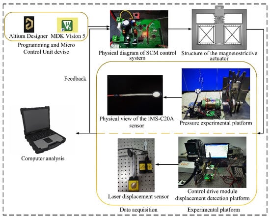
Figure 1.
System research flow chart.
2. Structural Design of Brake-By-Wire System
2.1. Design of Magnetostrictive Actuator
The overall design and structure scheme of a magnetostrictive actuator includes the selection of a GMM rod, calculation of coil turns, selection of external structural materials and size design of magnetostrictive actuator, size design of output rod, pre-pressure and magnetic yoke device design.
In this paper, the NJ-XL0004ZC was selected from the actual vehicle, and the known vehicle parameters are shown in Table 1.

Table 1.
Whole vehicle parameters table.
The known experimental vehicle axle loads is a = 945 mm, b = 1155 mm. Assuming that the adhesion coefficient of the common road surface of the car is 0.8, the friction coefficient of the initially selected friction plate is 0.5. When the car brakes, the normal reaction force of the ground acting on the front and rear wheels is:
The normal reaction forces of the ground acting on the front and rear wheels can be obtained as:
Therefore, ground adhesion is:
The largest known ground braking force:
It can be known that the maximum ground braking force of the brake is:
It can be seen from this that braking torque required on the axle is:
According to the above theory, from the pressing force of the brake disc can be known that braking torque is:
After it is known that the locking operation occurs, the required bearing torque of the front axle is:
The single-side pressing force required for the brake to lock is:
From the angle between the clamping force and the chamfer, it can be known that the angle between , and the GMM rod push rod is 30°, from which the minimum force that the GMM rod needs to output can be calculated:
It is obtained that the minimum output force of the GMM rod is , the minimum elongation is and the maximum elongation of the GMM rod is related to its own length, by the formula:
In the formula, is the length of the GMM rod, is the maximum elongation (saturated elongation) of the GMM rod, is the saturation magnetostriction ratio, is the designed minimum working displacement of the driver and is a mathematical factor, generally set on the line. If the value of is large, the difficulty of linearization will increase, but the material will be saved. When the output force requirement of the driver is at the maximum, working displacement is , therefore:
Then, .
Determine the selection of TX series rare earth GMM rods manufactured by Gansu Tianxing Rare Earth Functional Materials Co, Ltd. (Lanzhou, China), considering the specifications and reliability of performance, combined with the given standard size of the manufacturer, according to the comparison and analysis of the physical properties of the giant-magnetostrictive material. Set the selection of GMM rod as .
The drive coil provides the drive magnetic field for the giant-magnetostrictive drive. The design of the coil is an important driving force component of the entire magnetostrictive drive. Therefore, a reasonable design of its structure and quantity is particularly important. The number of turns of the coil affects whether the experimental internal devices can achieve saturation during operation; minimizing but also maximizing the electro-magnetic-mechanical conversion efficiency of the internal materials. When designing the structure of the excitation coil, it is necessary to take into account that the saturated driving magnetic field can meet the design requirements under the condition that the performance of the internal material is guaranteed to be maximized. In the actual working process of the driver, the excitation coil will produce a temperature thermal effect and magnetic leakage phenomenon during the experiment, which will affect the experimental accuracy and make the whole test effect less ideal; therefore, when designing the excitation coil structure, it is necessary to calculate the appropriate number of turns of the coil to reduce the influence of experimental errors. At the same time, it ensures that the magnetic field generated by the coil can reach the maximum and meet the design requirements.
The entire drive coil structure frame is a hollow cylinder, and the main parameters that need to be calculated and designed are the number of coils turns , the coil wire diameter and the length . During the experiment, considering that the coil will produce magnetic flux leakage when it is energized and working, resulting in errors in the experimental results, according to the relevant principles of Ampere’s theorem, all relevant losses including the magnetic flux leakage error are taken into account in the calculation. The calculation formula for the driving magnetic field of the driving coil is:
According to the design size parameters of the magnetostrictive rod, in order to achieve a better stretching coefficient, combined with the characteristics of the magnetostrictive material, the maximum driving magnetic field of the magnetostrictive rod is determined to be 80 kA/m. Due to the thickness of the coil and the loss during the winding process, the length of the designed GMM rod should be slightly less than the total length of the coil in general. When the magnetostrictive rod is working, the magnetic field is relatively uniform, and the expression is:
In the formula: K is the relative coefficient of length, and the range is between 1.05 and 1.1. In this design, K is taken as 1.05, and = 73.5 mm after calculation. In order to improve the electromagnetic conversion efficiency of the magnetostrictive rod, the inner diameter of the coil should be as close as possible to the diameter of the giant-magnetostrictive rod, and the inner diameter of the coil is 21 mm.
In order to ensure the stability of the experiment and reduce the loss of the experiment, the resistance value of the thinner enameled wire is too large, and it is easy to generate heat and cause damage, which has a great impact on its service life. Therefore, this paper designs and selects a larger diameter driving coil. The specific formula requirements are as follows:
In the above formula, the value of the coil current density of will change with the actual test environment requirements, and it can be divided into three cases: when the coil only needs to meet the short-term operation state, can be 13~30 ; when the coil repeats in a short time during operation, can take 5~12 ; when the coil needs to meet uninterrupted operation, can take 2~4 . represents the maximum effective value of the current passing through the coil. According to the experimental requirements, this paper needs to establish a magnetostrictive drive system in long-term repeated experiments, so is taken as 4 A. According to the input maximum drive current, is 4 A, the wire diameter of the enameled wire is finally determined to be 0.91 mm, and the integer value is 1 mm. The driving current of the coil is 4 A, and the number of turns of the driving coil can be determined to be 1390 turns after calculation with the above formula. In order to make the experiment more rigorous and minimize the influence of magnetic flux leakage on the expansion coefficient, the actual number of turns of the driving coil is designed to be 1400 turns.
During the experiment, it was considered that the magnetic leakage phenomenon would occur when the coil was energized, resulting in the error of the experimental results. According to the relevant principles of Ampere’s theorem, all relevant losses including the magnetic leakage error should be taken into account in the calculation. After the relevant formula calculation [13], component parameters are obtained as shown in Table 2.
Table 2.
Component parameters of the magnetostrictive actuator.
After comparative calculation and analysis, the device structure was drawn, and the selection of each part was confirmed. The structure diagram of the giant-magnetostrictive actuator prototype was obtained as shown in Figure 2.
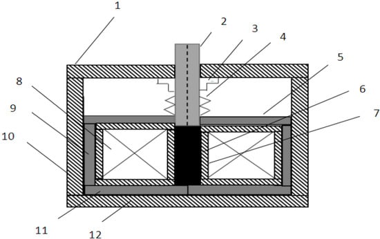
Figure 2.
Structure of the magnetostrictive actuator. (1) Upper end cover; (2) output rod; (3) preloading bolt device; (4) spiral spring; (5) upper magnet; (6) GMM rod; (7) coil frame; (8) winding coil; (9) magnetic side wall; (10) shell side wall; (11) lower magnetic body; (12) shell base.
2.2. Magnetostrictive Disc Brake Structure Design
First, disc brake compression force needed to be determined. It is known that the weight of the experimental vehicle was 800 kg, and the wheelbase was a = 945 mm, b = 1155 mm. It was assumed that the common road adhesion coefficient of the vehicle was = 0.8, and the friction coefficient of the friction plate was initially selected as = 0.5. According to the requirements, the brake structure parameters were calculated. The calculation process is detailed in references [14]. The structure diagram is shown in Figure 3:
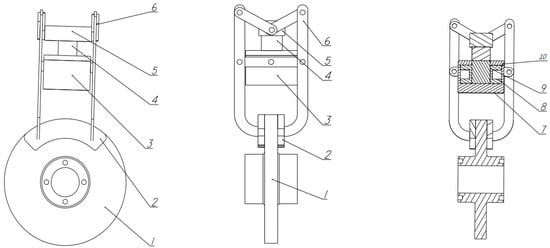
Figure 3.
Schematic structure of magnetostrictive disc brake. (1) Brake disc; (2) friction lining; (3) GMA; (4) push rod; (5) slide block; (6) transmission mechanism; (7) outer shell; (8) winding frame and coil; (9) GMM rod; (10) end cover.
As shown in Figure 3, according to the selection and test of the magnetostrictive actuator, the mechanical structure of the braking part of the magnetostrictive disc brake was further designed. The brake contains the giant-magnetostrictive actuator (3), which consists of the outer shell (7), the winding frame and coil (8), GMM rod (9) and end cover (10) (which also includes a retightening spring applying a retightening force and a magnetic yoke sealing magnetic circuit). When the giant-magnetostrictive actuator receives the braking signal, the winding frame coil (8) passes a current and generates the corresponding magnetic field. In the GMM rod (9) occurs a corresponding deformation and displacement under the action of the magnetic field based on the magnetostrictive effect. Through the push rod (4) and (5), a slider will be passed to the force created by the magnetostrictive rod (9). Finally, the force generated by the magnetostrictive rod (9) is transmitted by the transmission mechanism (6) to the friction lining (2) and the brake disc (1). The brake disc is clamped with the friction lining so as to achieve the effect of decelerating or stopping the vehicle.
3. Hardware Design of Control System
The closed-loop control system with a giant-magnetostrictive actuator is composed of a driving power supply, a sensor conveying unit, an SCM control system and a controlled unit. Compared with the traditional closed-loop control system, the controlled unit of the system is also the driving unit of the braking part. The hardware circuit design of the controlled unit should be based on the characteristics of the driving component.
Hardware Circuit Design
After understanding and comparing the performance of the single-chip microcomputer, this paper selected STM32F103C8T6 as the total control unit of the overall magnetostrictive disc brake mechanism control circuit system. STM32 belongs to a version of the arm core, which is more convenient to use than the traditional 51 single-chip microcomputer and abolished. Compared with the 51 single-chip microcomputer structure, it is more optimized than the machine cycle. In terms of software programming, STM32 includes programs of related modules, including multiple external ports to facilitate the design of system links, and the internal functions are simple and easy to operate, which can also improve work efficiency.
In this paper, STM32F103C8T6 was selected as the overall control unit of the magnetostrictive disc brake mechanism. STM32 includes related module programs, including a number of external ports to facilitate the design of system links, simple internal functions and easy operation, which can also improve work efficiency. A pin diagram is shown in Figure 4.

Figure 4.
STM32F203C8T6 pin diagram.
Figure 5 shows the basic hardware circuit diagram of the control system. The hardware circuit of the control system of the giant-magnetostrictive actuator was mainly composed of a detection channel, a single-chip control unit, a peripheral circuit, an analog input channel, an analog output channel and other modules. The SCM control unit included a power module, a crystal oscillator circuit, a decoupling circuit, etc. Analog input channels included photoelectric coupling, signal holding and transmission circuits. The driver of these modules can be programmed by SCM software to control the automatic operation function. According to experimental requirements, a relevant peripheral circuit was designed to achieve the corresponding signal transmission.
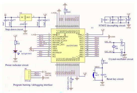
Figure 5.
Microcontroller and related basic circuit diagram.
A SEPIC circuit was selected as the main circuit to achieve the effect of system voltage rising and falling. A calculation of related components was carried out. A SEPIC circuit schematic diagram is shown in Figure 6.
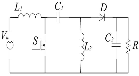
Figure 6.
SEPIC circuit schematic diagram.
The SEPIC circuit provided a driving current for the excitation coil of the giant-magnetostrictive rod. The main components such as inductor, polyester capacitor, cement resistor, large capacity electrolytic capacitor, fast recovery diode and induction furnace power tube FGA25N120 were used. The circuit of the control process is as follows: when it receives the braking signal, the MCU outputs PWM signals with different duty cycles through the brake signal strength output by the electronic brake pedal. The signal controls the opening and closing of the photoelectric coupler, and then controls the cut-off and conduction of the power tube, making the SEPIC circuit turn on and off continuously, so as to output driving currents of different intensities. The electromagnetic coil generates excitation magnetic fields with different intensities, which makes the giant-magnetostrictive rod output a corresponding displacement, so as to promote the friction lining, eliminate the braking gap between the friction lining and the brake disc and act on the brake disc with a corresponding driving force to realize braking of the vehicle.
After calculation [15], C19 and C20 in the figure were selected, respectively: C19 = 47 µF, C20 = 220 µF. Quick turn-off diode MUR1560 was selected. According to the actual model, it was determined that L2 = L3 = L4 = 171.84 µH in the design drawing. IGBT FGA25N120 was confirmed after the comparison of the switch tube experiment. It was designed to control the opening and closing of IGBT and design the isolation function to prevent the circuit damage caused by excessive load. The circuit principle and isolation circuit diagram of lifting voltage are shown in Figure 7:
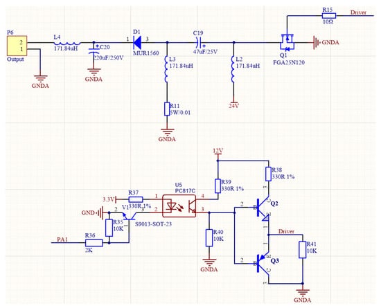
Figure 7.
Schematic diagram of the external voltage lifting circuit.
At present, a 12 or 24 V power supply system is generally used as a vehicle power supply (42 V power supply for a few new cars). In this paper, a 24 V switching power supply was selected as the main power supply of the automobile brake-by-wire system. According to the voltage regulator conversion principle shown in Figure 8, AMS1117 and L7812 voltage regulator chips were selected to meet the voltage requirements of 5 V and 12 V. B1205S was used for DC-DC isolated power supply, which was used to isolate the single output of unregulated voltage and protect the output short circuit.
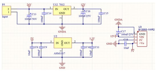
Figure 8.
Voltage regulator conversion principle diagram.
As the design of output power was large, the ground wire was designed separately at the edge of the welding plate to prevent mutual interference with small signals. The size of the ground wire was enlarged to reduce the coupling noise. The wiring must be classified according to different functions and performance of components and divided into different subsystems so that the wiring direction is consistent with signal transmission. The core plate was finally welded as shown in Figure 9.
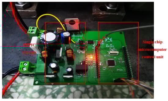
Figure 9.
Physical diagram of SCM control system.
4. Software Design of Control System
The software part of the control system was written by the STM32 processing platform developed by Keil Software Company (Grasbrunn, Germany), and the external clock source used in the system was of 8 MHz frequency.
The microcontroller will automatically call the subroutine according to the status of the sensor and collect the signal of the pedal angle. After pulse width modulation, the control output voltage signal is obtained. The data is collected through the pressure sensor, and the obtained pressure value is fed back to the MCU hardware system. The deviation is calculated and processed by using the PID control algorithm. By adjusting the brake pedal sensor to change the current of the giant-magnetostrictive actuator, the control of giant-magnetostrictive brake-by-wire system is realized. Figure 10 is the flowchart of the main program of the system.
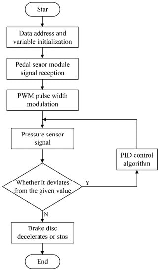
Figure 10.
Main control flow chart of the system.
4.1. Sensor Selection and Transformer Design
4.1.1. Selection of Pedal Sensor
In this paper, the angle sensor MPU6050 (Invensense, Sunnyvale, CA, USA) was selected, and the brake pedal change signal was transmitted to the MCU for analysis and processing. Figure 11 shows the detection shaft of the MPU6050 sensor.
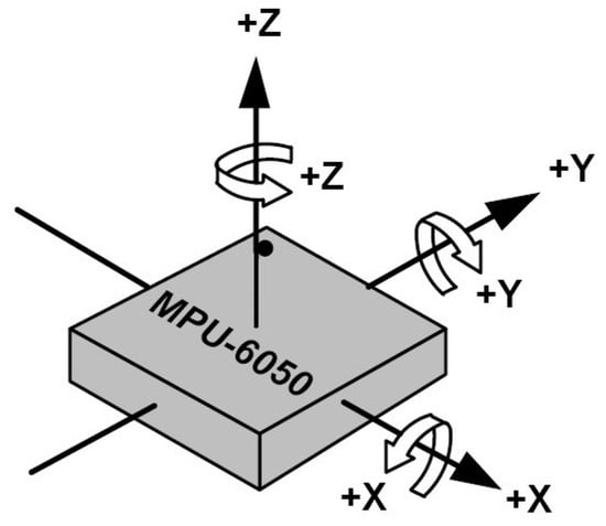
Figure 11.
MPU6050 detection axis.
The detection direction required in the experiment is the movement direction shown in the X axis.
The MPU6050 simulation brake pedal signal transmission to the single-chip computer, and transmitted through the microcontroller, reads to the debug computer end. When the brake pedal is not functioning, the analog signals in three x, y, z directions the acceleration value close to zero, there is a weak electric signal, three-dimensional display tends to be horizontal, and the simulator with single-chip microcomputer pedal change waits.
MPU6050 can display the real-time motion of the brake pedal and output different voltage signals according to the different motion amplitude. The changing brake signal was combined with the PWM program to realize the pedal control circuit on and off, so as to change the voltage.
4.1.2. Transformer Module Design
PWM pulse width debugging analog control is a very effective technology. It mainly uses the digital signal generated by the microprocessor to control the analog circuit. Figure 12 shows the schematic diagram of PWM principle.
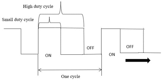
Figure 12.
PWM control waveform.
According to the relevant principles of PWM and the design scheme, the relationship between PWM control duty ratio and the final output voltage is calculated, and the corresponding theoretical calculation value is shown in Table 3:
Table 3.
Relationship between PWM input duty cycle and output voltage.
Using timer 2 initial PWM signal, output PWM wave with a variable duty cycle to drive the SEPIC circuit IGBT switching frequency, so as to control voltage rise and fall.
4.1.3. Voltage Feedback Module Selection
In this paper, IMS004-C20A (referred to as IMS-C20A) of Aida Film Electronics was selected, which is also a piezoresistive sensor very reliable as a pressure test sensor. The pressure value of magnetostrictive rod excitation is transmitted to the microcontroller for error analysis. The pressure detection flow chart combined with the PID algorithm control is shown in Figure 13.
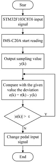
Figure 13.
Voltage feedback flow chart.
The relevant program of the pressure sensor was imported, the pressure value was received from the piezoresistive sensor, and the value of the pressure sensor was detected according to the change of the input signal of the brake pedal to judge whether the system could produce the corresponding braking effect. The physical picture is shown in Figure 14.
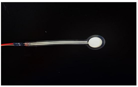
Figure 14.
Physical view of the IMS-C20A sensor.
As shown in Figure 15, when the magnetostrictive rod was affected by the magnetic field and produced upward displacement, the pressure signal increased gradually with the 0–4 A current under 24 V voltage and produced the braking effect. The pressure signal was converted into a voltage signal and then the latter was fed back to the MCU for comparison to complete error elimination.
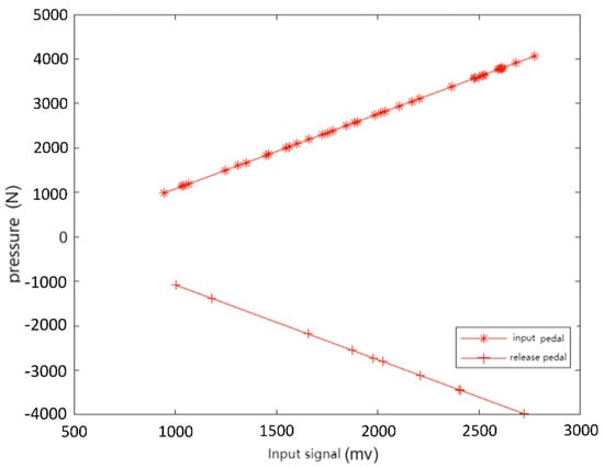
Figure 15.
Pressure test of the IMS-C20A sensor.
5. Experimental Testing and Analysis
The control system module was tested on the overall test bench. The experiment consisted of two parts which were aimed at verifying the final effect of the control system design. Firstly, this experiment intended to verify whether the giant-magnetostrictive actuator could produce a corresponding displacement under when different forces were exerted. Secondly, the experiment intended to verify whether the thrust in the giant-magnetostrictive actuator could meet the needs of the experiment.
For the first part, the optical vibration isolation platform and laser displacement sampler were used for displacement numerical detection to verify whether the design of the control system could meet the experimental requirements. The experimental data was compared with theoretical calculation value. Figure 16 shows the platform construction.
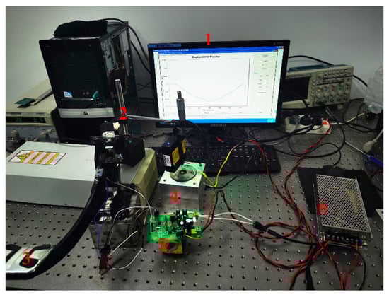
Figure 16.
Control drive module displacement detection platform. (1) Laser displacement data sampling display; (2) LTS-025-02 laser displacement sensor; (3) electronic brake pedal (4) magnetostrictive drive structure; (5) MCU system control module (6) switch power supply.
As shown in the figure above, through the detection of displacement value it was verified that the single-chip microcomputer control unit designed could provide the changed voltage and current for the giant-magnetostrictive actuator, so that the magnetostrictive rod produced elongation displacement. In order to verify the feasibility of system, three cases of the giant-magnetostrictive displacement were detected, respectively. When the pitching angle of the brake pedal sensor was close to 20 degrees, 35 degrees and 50 degrees, the displacement generated by the braking system was detected. By adjusting the duty ratio function setting, when the pitch angle was 20 degrees, the duty ratio was set to 30%, and the output voltage was about 10 V. The duty cycle was adjusted to 50% at 35 degrees, and the output voltage was about 24 V. The duty cycle was adjusted to 70% at 50 degrees, and the output voltage was about 50 V. Experimental comparison of several cases is shown in Figure 17. The displacement of the giant-magnetostrictive rod was analyzed under the conditions of fast and slow braking. Two different braking conditions were tested at 50 degrees as shown in Figure 18.
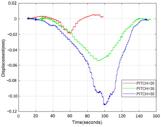
Figure 17.
Displacement curves of pedal angle in different states.
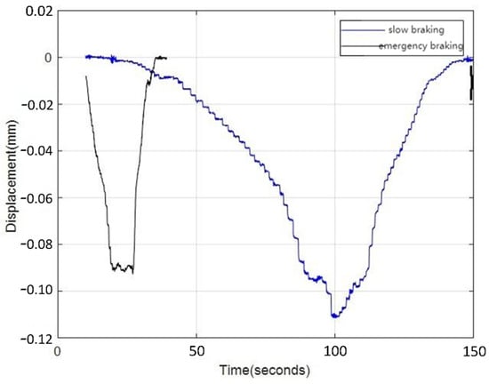
Figure 18.
Displacement effect in two different states.
It can be clearly seen from Figure 17 that according to the different inclination angles of the pedal sensor, the hardware drive module controlled the power supply to input different voltages to the coil, and the inclination angle was positively correlated with the output voltage. When the pedal sensor tilt angle was small, the power input voltage was also small; as the inclination angle of the pedal sensor increased, the power input voltage increased, and at the same time, the magnetostrictive rod was deformed by the magnetic field on the coil. The greater the voltage on the coil, the stronger the magnetic field generated by the coil and the greater the elongation of the giant-magnetostrictive rod. When the voltage on the coil was zero, the magnetic field disappeared and the magnetostrictive rod was restored.
The experimental results show that when the inclination angle of the pedal sensor was 20 degrees, the maximum displacement of the giant-magnetostrictive rod could reach 0.019923 mm; when the inclination angle of the pedal sensor was 35 degrees, the maximum displacement of the giant-magnetostrictive rod could reach 0.053243 mm; when the inclination angle of the pedal sensor was 50 degrees, the maximum displacement of the giant-magnetostrictive rod could reach 0.111393 mm, which was very close to the theoretical maximum elongation of 0.112 mm calculated in Section 2, and the output braking force was also the largest at this time. This result proved that the giant-magnetostrictive rod could be deformed under the driving of the hardware driving module designed in this paper, and the deformation amount satisfied the theoretical calculation value.
Figure 18 reflects the response of the giant-magnetostrictive rod driven by the hardware drive circuit when the brake pedal inclination angle reached 50 degrees. The data in the figure shows that when the brake pedal was normally pressed to reach the inclination angle of 50 degrees, the giant-magnetostrictive rod reached the maximum elongation of 0.111393 mm. When the brake pedal was quickly stepped down to reach the inclination angle of 50 degrees, the elongation of the giant-magnetostrictive rod was not reached, because only a part of the magnetic domains in the giant-magnetostrictive rod could be restored to a free state under the influence of repeated experiments, so the displacement generated by the giant-magnetostrictive rod could not reach the theoretical maximum value, but this did not affect the final braking effect.
The second part verified whether the upward thrust of the magnetostrictive rod in the giant-magnetostrictive actuator could meet the requirements of the experiment, which was reflected by the size of the push rod (4) and the IMS-C20A pressure sensor in the transmission mechanism (6) mentioned in Section 2. The single-chip microcomputer control system started from a 24 V switching power supply. Through the voltage transformation circuit and digital to analog conversion, the voltage value was transmitted to the gaint-magnetostrictive actuator, and the pressure sensor detected the signal and fed back to the single-chip microcomputer system. The pressure experimental platform is shown in Figure 19.
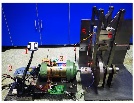
Figure 19.
Pressure experimental platform. (1) Electronic brake pedal; (2) switching power supply; (3) driving motor; (4) single-chip microcomputer system control module; (5) IMS-C20A sensor; (6) disc brake bench.
The pedal sensor transmitted the signal to the single-chip microcomputer, which transmitted the converted digital voltage and current signal to the giant-magnetostrictive actuator, the magnetostrictive rod generated pressure in the magnetic field. The correctness and feasibility of the control system were verified by the measurement of the value of the pressure sensor. Similarly, pressure changes under three different initial values were tested. When the pitch angle value of the brake pedal sensor was close to 20 degrees, 35 degrees and 50 degrees, the pressure changes were as follows.
It can be seen from Figure 20, Figure 21 and Figure 22 that the pressure generated by the magnetostrictive rod was in a linear relationship with the angle of pedal sensor. When the angle of the pedal was larger, the pressure generated by the deformation of the magnetostrictive rod was larger. The experiment data showed that when the maximum angle was reached, the maximum pressure could reach 3883 N, which could meet the requirements of the theoretical calculation of 3631 N in Section 2. When the angle of the pedal was small, the braking effect produced by the giant-magnetostrictive actuator was weak. The experimental data proved that the brake-by-wire system designed in this paper agreed with the theoretical calculation results and achieved the expected performance.
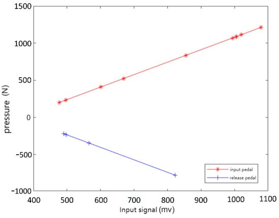
Figure 20.
Pressure test diagram when the pedal reached 20 degrees.
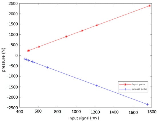
Figure 21.
Pressure test diagram when the pedal reached 35 degrees.
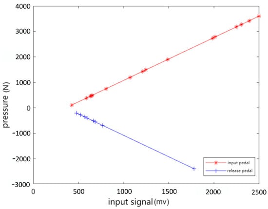
Figure 22.
Pressure test diagram when the pedal reached 50 degrees.
6. Conclusions
According to the micro displacement closed-loop control principle of a giant-magnetostrictive actuator, the control unit of a giant-magnetostrictive brake-by-wire system was designed based on the development component of a single-chip microcomputer. Based on the testbed of a giant-magnetostrictive brake-by-wire system, the deformation and output pressure of a giant-magnetostrictive actuator were tested. The relevant test results were highly consistent with the theoretical calculation values, which verified the correctness and effectiveness of the control system design. The giant-magnetostrictive brake-by-wire system provides a new way for the development of intelligent vehicle brake-by-wire systems. Here are the conclusions:
(1) According to the selected model, the vehicle’s ground braking force calculation was carried out; the obtained calculation results were used as the design basis for the giant-magnetostrictive brake-by-wire system; the number of turns of the GMA coil was 1400 turns, and the maximum output displacement was 0.112 mm.
(2) According to the bench experiment, when the maximum current was 4 A, the measured deformation was 0.111393 mm, and the maximum output force was 3883 N; the measured results were highly consistent with the theoretical calculation values, which verified the correctness of the theoretical calculation.
Author Contributions
Conceptualization, C.C.; formal analysis, R.Z.; funding acquisition, C.C.; software, X.J. All authors have read and agreed to the published version of the manuscript.
Funding
This work was financially supported by the Natural Science Foundation of China (Grant No. 51865032) and the project of Jiangxi Provincial Department of Education (Grant No. GJJ190981).
Institutional Review Board Statement
Not applicable.
Informed Consent Statement
Not applicable.
Data Availability Statement
Data is contained within the article.
Conflicts of Interest
The authors declare no conflict of interest.
References
- Zong, C.F.; Li, G.; Zheng, H.Y.; He, L.; Zhang, Z.X. Study Progress and Outlook of Chassis Control Technology for X-by-wire Automobile. China J. Highw. Transp. 2013, 26, 160–176. [Google Scholar]
- Fu, Y.F.; Hu, X.H.; Wang, W.R.; Ge, Z. Simulation and experimental study of a new electromechanical brake with automatic wear adjustment function. Int. J. Automot. Technol. 2020, 21, 227–238. [Google Scholar] [CrossRef]
- Bill, K.; Balz, J.; Dusil, V. Electromechanical Disc Brake. U.S. Patent No. 6,158,558, 12 December 2000. [Google Scholar]
- Keller, F. Electromagnetic Wheel Brake Device. U.S. Patent No. 6,536,561, 25 March 2003. [Google Scholar]
- Gombert, B.; Guttenberg, P. The electronic wedge brake. ATZ Worldw. 2006, 108, 2–5. [Google Scholar] [CrossRef]
- Hasan, M.H.C.; Hassan, M.K.; Ahmad, F.; Marhaban, M.H. Modelling and design of optimized electronic wedge brake. In Proceedings of the 2019 IEEE International Conference on Automatic Control and Intelligent Systems (I2CACIS), Selangor, Malaysia, 29 June 2019. [Google Scholar]
- Jo, C.H.; Lee, S.M.; Song, H.L.; Cho, Y.S.; Kim, I.; Hyun, D.Y.; Kim, H.S. Design and control of an upper-wedge-type electronic brake. J. Automob. Eng. 2010, 224, 1393–1405. [Google Scholar] [CrossRef]
- Hwang, Y.; Choi, S.B. Robust control of electronic wedge brake with adaptive pad friction estimation. Int. J. Veh. Des. 2013, 62, 165–187. [Google Scholar] [CrossRef]
- Jo, C.; Hwang, S.-H.; Kim, H. Clamping-force control for electromechanical brake. IEEE Trans. Veh. Technol. 2010, 59, 3205–3212. [Google Scholar] [CrossRef]
- Kwon, S.-B.; Kwon, Y.-D.; Lee, S.-J.; Shin, S.-Y.; Kim, G.-Y. Numerical analysis for the coating thickness prediction in continuous hot-dip galvanizing. J. Mech. Sci. Technol. 2009, 23, 3471–3478. [Google Scholar] [CrossRef]
- Ki, Y.H.; Lee, K.J.; Cheon, J.S.; Ahn, H.S. Design and implementation of a new clamping force estimator in electro-mechanical brake systems. Int. J. Automot. Technol. 2013, 14, 739–745. [Google Scholar] [CrossRef]
- Yu, Z.; Han, W.; Xu, S.; Xiong, L. Review on hydraulic pressure control of electro-hydraulic brake system. J. Mech. Eng. 2017, 53, 1–15. [Google Scholar] [CrossRef]
- Wang, A.-M.; Meng, J.-J.; Xu, R.-X.; He, C.-X. Structural optimization and dynamic performance study of super magnetostrictive exciter. Vib. Shock. 2019, 38, 184–190. [Google Scholar]
- Chu, C.; Xu, Q.; Jia, X.; Zhang, X.; Xiao, Y. Parameterized Structure Design of Giant-magnetostrictive Disc Brake. J. Phys. Conf. Ser. 2021, 1865, 032031. [Google Scholar] [CrossRef]
- Gao, S.; Zhao, S.; Zhang, L.; Li, J. A new high gain DC/DC converter based on Sepic. Electron. Technol. Appl. 2021, 47, 108–111. [Google Scholar]
Publisher’s Note: MDPI stays neutral with regard to jurisdictional claims in published maps and institutional affiliations. |
© 2022 by the authors. Licensee MDPI, Basel, Switzerland. This article is an open access article distributed under the terms and conditions of the Creative Commons Attribution (CC BY) license (https://creativecommons.org/licenses/by/4.0/).