Article

On the Performance of a Modified Triple Stack Blade Savonius Wind Turbine as a Function of Geometrical Parameters

by
Reza Norouztabar
1,
Seyed Soheil Mousavi Ajarostaghi
2,
Seyed Sina Mousavi
3,
Payam Nejat
4,5,
Seyed Saeid Rahimian Koloor
6 and
Mohamed Eldessouki
6,7,8,*
1
Department of Mechanical Engineering, Mazandaran University of Science and Technology, Babol 47166-85635, Iran
2
Mechanical Engineering Department, Université de Sherbrooke, Sherbrooke, QC J1K 2R1, Canada
3
Department of Civil Engineering, Babol Noshirvani University of Technology, Babol 47148-71167, Iran
4
Advanced Building and Environment Research (ABER), 99420 Weimar, Germany
5
Department of Building Physics, Bauhaus-University Weimar, 99420 Weimar, Germany
6
Institute for Nanomaterials, Advanced Technologies and Innovation, Technical University of Liberec, 461 17 Liberec, Czech Republic
7
Empa, Swiss Federal Laboratories for Materials Science and Technology, Laboratory for Biomimetic, Membranes and Textiles, CH-9014 St. Gallen, Switzerland
8
Faculty of Engineering, Mansoura University, Mansoura 35516, Egypt
*
Author to whom correspondence should be addressed.
Sustainability 2022, 14(16), 9816; https://doi.org/10.3390/su14169816
Submission received: 24 May 2022 / Revised: 20 July 2022 / Accepted: 31 July 2022 / Published: 9 August 2022

Abstract

:
The Savonius wind turbine is one of the most well-known vertical axis wind turbines with insensitivity to wind direction, flow turbulence, and high torque generation. These turbines can extract up to 20% of the energy from the wind. This study numerically analyzes the performance of a modified Savonius wind turbine equipped with secondary blades and slots. The k-ε standard method is used to simulate the turbulence flow around the turbine, and the simulation is performed using the ANSYS FLUENT 18.2 commercial code. The effects of distance between the main blade and the secondary blade, position of the secondary blade, the width of the main blade’s slot, and the profile of the secondary blade on the produced torque are studied and analyzed. The simulation is performed at four wind velocities: 3, 4, 5, and 6 m/s. The results showed that the output torque at the secondary blade angular position β = 130 is higher than other angles. Furthermore, by increasing the radius of the additional blade from R = 25 to 43 mm, the torque is improved, and the area below the output torque curve is increased. Moreover, the results showed that creating a slot on the main blade equipped with a secondary blade has a significant impact on the produced torque; however, the geometrical parameters of the proposed rotors should be adjusted accurately to find the best case in terms of the produced torque.

1. Introduction

Today, renewable energies are one of the most important sources of energy supply and most researchers are trying to improve the performance of these systems [1]. The most important sources of renewable energy include solar energy [2,3], geothermal energy [4,5], wind energy [6], etc.
Wind energy is geographically extensive, simultaneously scattered and decentralized, and almost always available [7]. However, this energy source has an oscillating and intermittent nature and does not have a constant airflow [8]. Therefore, for thousands of years, humans have used only a tiny part of it using windmills. However, due to environmental problems and climate change issues, there is a trend of reducing dependence on fossil energy resources and increasing the use of wind [9,10].
The wind turbine is categorized according to its central axis into (1) the horizontal axis wind turbine; and (2) the vertical axis wind turbine. Vertical axial wind turbines are more suitable for obtaining energy at low wind speeds [11]. However, wind currents in urban areas are always turbulent due to obstacles such as trees and high buildings and are very different from the flow in non-urban areas. In recent studies, the rate of turbulence has been reported to be 50 to 100 percent. Horizontal axis wind turbines do not perform better than the vertical axis type in turbulent wind currents [12]. This turbulent flow and constant changes in wind direction can lead to a 75% increase in horizontal axis turbine fatigue [13]. In addition, the small turbines can be used for conditions with 25% more load than conventional and industrial turbines [14,15]. Therefore, it is more appropriate to use vertical axis turbines with more fatigue resistance. Especially since these types of turbines have a lower rotational speed and produce less noise, turbulence has no significant influence on the performance of their various models, particularly turbines that work with drag force [16,17].
Turbine starting speed is one of the most important parameters considered in small-scale wind turbines and can be attributed to the lower average wind speed in urban and residential areas than in non-residential and suburban areas. The installed turbines must be able to generate electricity at this low speed. Horizontal axis turbines are static and motionless for about 21% of the year. Laboratory research has shown that, on average, horizontal axis turbines can operate properly at speeds of more than 2.5 m/s [18]. The Savonius is one of the most well-known models of vertical axis wind turbines. This type of turbine was first introduced by a Finnish engineer named Savonius in 1929 [19]. This type of turbine features low sensitivity to wind turbulence and high torque generation. These turbines can extract up to 20% of the energy from the wind [20].
So far, numerous research has been conducted on the performance and simulation of Savonius turbines. Mohammad Hadi Ali [21] conducted a laboratory study on two-blade and three-blade vertical Savonius wind turbines. The results showed that the power and torque coefficient in the three-blade turbine are better than in the two-blade one. Debnath and Gupta [22] examined the Savonius wind turbines using spiral blades. Results showed that the highest and the lowest torques correspond to the rotor angles of 60 degrees and 150 degrees, respectively. Deb and Gupta [23] examined the performance of a double-blade vertical axis wind turbine numerically and observed that the highest static pressure occurs at 90 and 270 degrees. Yoshida and Kawamura [24] studied the effect of rotor blade curvature on power factors. This study showed that the greater the depth of the blade, the better the output power factor. McTavish et al. [25] presented an advanced model of the Savonius wind turbine. In that proposed model, the blade walls were designed to generate additional torque by shrinking the incoming airflow. Brown and Brooks [26] also examined power transfer due to wind to the rotor in vertical-axis turbine blades made of composite materials [27]. This study found that the turbine rotation causes many changes in the angle of its blade attack, which can be shown as a failure in the composite structure [27,28]. The interaction between turbine blades and wind can lead to dynamic failure, sudden intensification, and aerodynamic loading changes on the blade. Armstrong et al. [29] also examined the aerodynamic loading on the turbine with the vertical axis of the direct blade. After conducting several experiments in wind tunnels and under different conditions, they determined the constant step effect of direct sloping blades in the wind with velocity V = 8 m/s. In other work, Armstrong and Tullis [30] evaluated a new kind of vertical axis turbine with helical blades experimentally. Various geometrical and operational conditions were tested and analyzed. Obtained practical results showed that canted blades presented more output power in comparison with simple straight blades. Furthermore, aerodynamic fences can be employed to improve the performance of the vertical axis turbine.
Chan et al. [31] optimized the blades of the Savonius wind turbine by employing CFD and a genetic algorithm. Accordingly, they achieved the enhancement in power coefficient by about 33% in the turbine with optimal dimensions, which belongs to the case of a tip speed ratio (TSR) of 0.8. Ferrari et al. [32] evaluated the dynamic behavior of the Savonius wind turbine numerically. The numerical simulations were performed by OpenFOAM code, and the k-ω SST turbulence model was employed to model the wind flow. The simulations were done for various TSRs and rotor angular speeds. According to the obtained numerical results, the case with TSR = 0.8 and aspect ratio = 1.1 showed the best performance. Kothe et al. [33] investigated the performance of a Savonius wind turbine with a 180° twisted helical profile experimentally and numerically. Results indicated that wind turbines with helical blades produce higher torque than non-helical ones. Accordingly, the highest power coefficient belongs to the case of TSR = 0.65. Mauro et al. [34] evaluated numerically the utilization of a ducted Savonius turbine for oscillating water column wave energy converters (OWCs). The presented results showed that the proposed turbine is very promising for this application. Bethi et al. [35] designed a Savonius wind turbine to generate power from the gust produced by trains. The optimization method was employed to find the best configuration and location of the proposed turbine. The obtained numerical results showed that the proposed energy production could be a viable method to provide the required electricity in the tunnel. In addition to the works mentioned above, some studies evaluated the performance of the Savonius wind turbine [36,37].
According to the mentioned literature review [38,39], it can be concluded that there is a lack of investigation into the performance of the triple-blade Savonius wind turbine. In this study, a modified triple-blade Savonius rotor at different wind velocities of 3 to 6 m/s (according to the previous relevant works [21,40]) is considered and evaluated comprehensively. The present work consists of five sections. In the first step, the effect of adding a secondary blade to the main blade of the considered triple-blade wind turbine on the produced torque is studied. The second step concentrates on the distance between the main and secondary blades on the produced torques. Four values are considered for the distance between the blades, including 6, 12, 18, and 24 mm. In the third step, to improve the performance of the triple-blade Savonius wind turbine, a slot is considered and placed on the main blade equipped with secondary blades to reduce the negative pressure behind the blades, and the obtained numerical results are compared and presented. Next, the slot width effect is evaluated, and four values, including 4, 8, 12, and 16 mm, are considered for the slot’s width. The impact of the angular position of the secondary blade with the slot was investigated in the fourth section. Five various angular positions are considered, including 50, 70, 90, 110, and 130 degrees. In the final section, the secondary blade profile (or radius) impact was studied numerically by considering three values for the radius of the secondary blade with the slot, including 25, 34, and 43 mm.

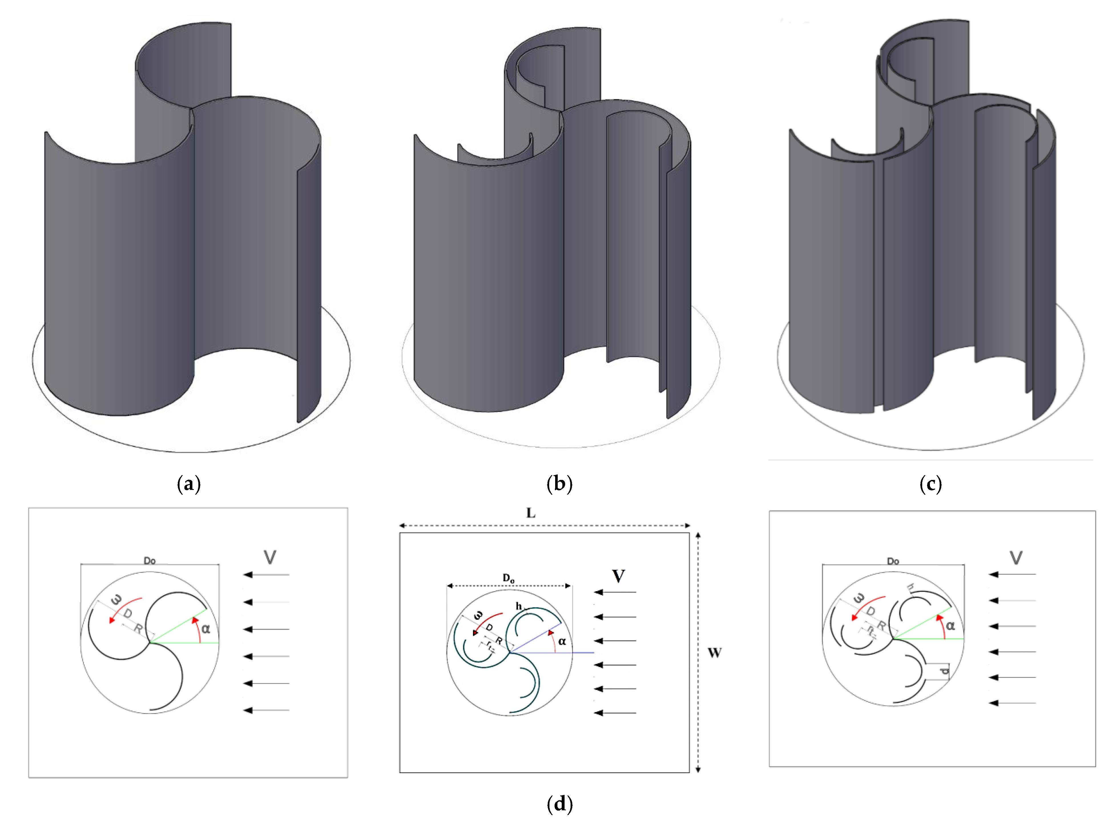
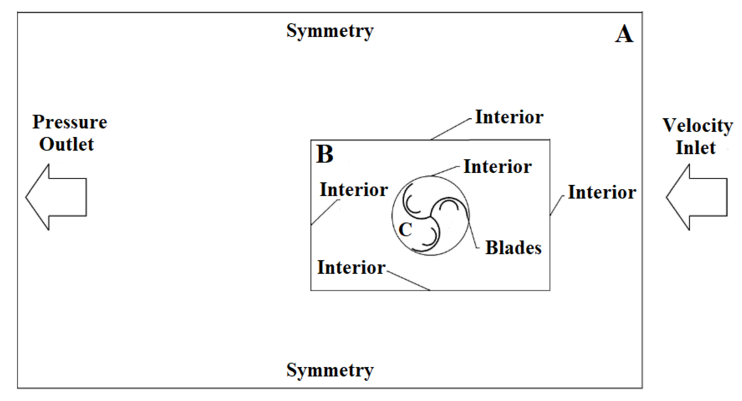
2. Problem Description
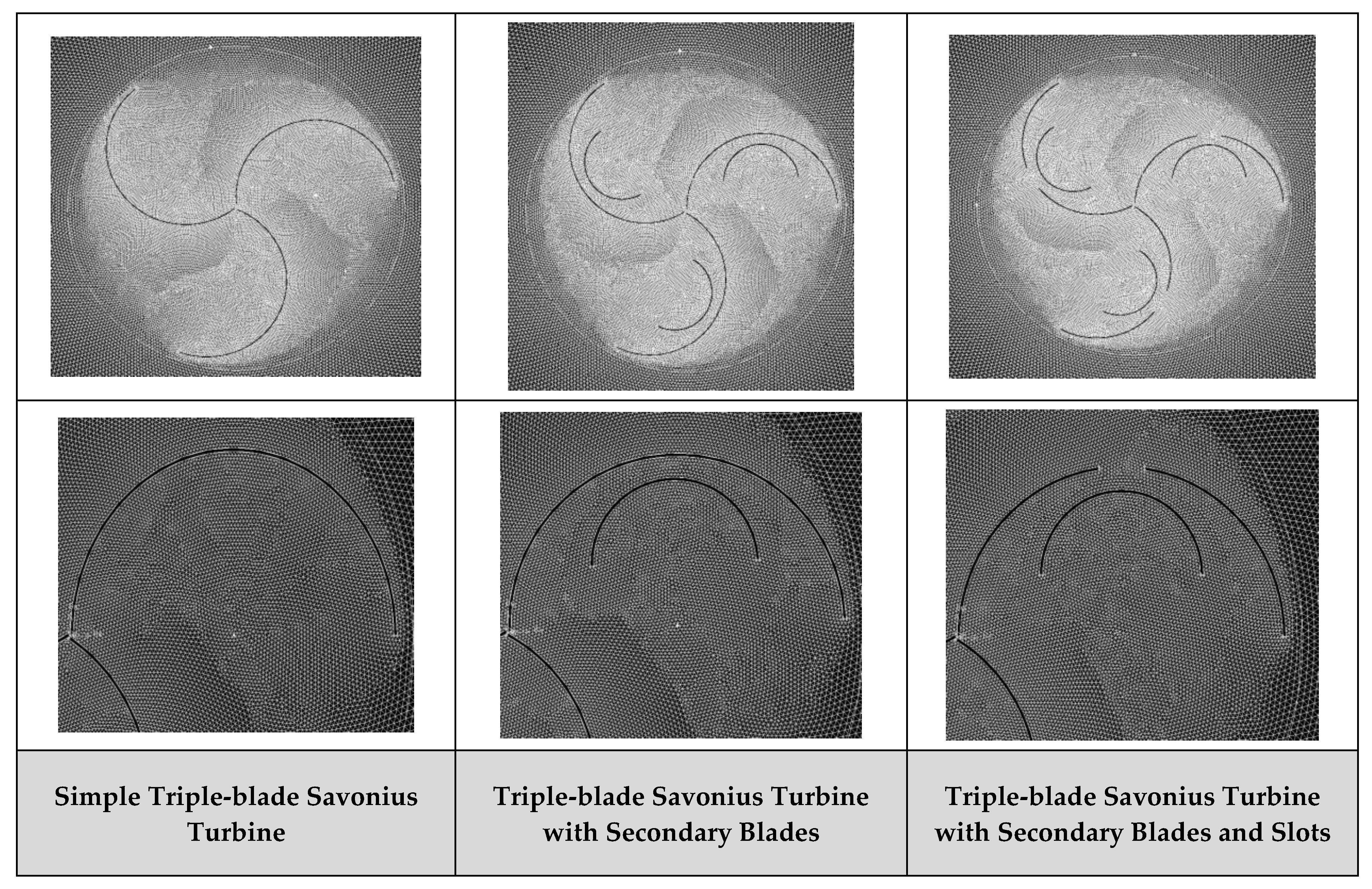
In this study, the examined rotor was a modified triple-blade Savonius wind turbine. This type of turbine is suitable for home use and the production of the required energy. These turbines are driven by a drag force applied to a half-cylinder by the wind as a flowing fluid [41]. The geometrical characteristics of the computational domain are given in Table 1.
Figure 1a shows a 3D schematic of a simple triple-blade Savonius turbine rotor. Accordingly, a semicircle with a diameter of 100 mm and an outer diameter of 200 mm was used as the main rotor. Figure 1b shows the 3D schematic of a triple-blade Savonius rotor with additional blades (or secondary blades) in which the diameter of the secondary blade is 50 mm. Figure 1c also shows a 3D schematic of the triple-blade Savonius rotor with an additional blade and a slot on the main blade as the modified rotor. The 2D computational domains of each section are shown in Figure 1d.

3. Numerical Method

The commercial CFD code, ANSYS FLUENT 18.2, is used to evaluate the performance of the vertical axis turbine of the Savonius type numerically. For the two-dimensional simulation of rotor rotation in a steady state, the reference model of rotational coordinates was used. In order to simulate the rotation of the rotor in the steady state condition, the Moving Reference Frame (MRF) [42] strategy was applied. In this solution strategy, the control volume is divided into two sub-domains. The first sub-domain consists of the rotor and the space around it that has a constant angular velocity proportional to the inlet wind speed and the blade tip’s velocity. The second one is without rotational velocity and just contains the wind velocity. The utilized boundary conditions for the 2D computational domain are illustrated in Figure 2. In this method, the control volume is divided into three subsets. The first set (see C section in Figure 2) includes the rotor and its surrounding space, which has a constant rotational speed proportional to the inlet wind velocity and the velocity of the blade tip. The second set (see B section in Figure 2) has no rotational speed and its grid depends strongly on the C section. The third set (see A section in Figure 2) also has no rotational speed and only has an inlet wind velocity.

4. Governing Equations

Mathematical equations can be defined as a combination of independent and dependent variables and relative parameters as differential equations that govern physical phenomena. The governing equations are presented as follows [42].

4.1. Continuity

Since this problem is studied independently of time and in a steady-state condition, the time parameter is removed from the equations. Therefore, the continuity equation is as follows:
x i ρ u ¯ i = 0

4.2. Momentum

For the two-dimensional compressible flow, the Navier-Stokes equation is as follows:
ρ xi ( ρ u i ¯   u j ¯ ) = P ¯ xi + xi [ µ u i ¯   x j ρ u i ¯   u j ¯ ] = 0
where µ indicates molecular viscosity, P ¯ is the mean pressure and −ρ   u i ¯   u j ¯ is the Reynolds stress. Considering that this problem is solved as a turbulent flow, the k-ɛ turbulent model is utilized here. The Reynolds stress is modeled for the momentum equations as follows:
ρ u i ¯   u j ¯ =   μ t [ u i ¯ x j + u j ¯ x i ] 2 3 δ ij [ ρ k + μ t u i ¯ x i ]
where k is the turbulent kinetic energy and μt is the turbulent viscosity. To calculate the turbulence viscosity for turbulent models such as k-ɛ, two additional equations must be solved. These two equations show how to calculate the turbulent kinetic energy, k, and turbulent dissipation rate, ɛ.
To introduce these two equations, the physics of the problem must be considered. Since rotating physics is considered, the Standard k-ε model has been used among the turbulent available models. In turbulent flow, rotation and circulation of the mainstream significantly affect the behavior of the flow. The Standard k-ε model covers different applications of turbulence flows [42]. Therefore, the equations for k and ε are as follows:
xj ( ρ   k u i ) = xj [ ( α k μ eff )   k xj ] + G k - ρ ε
xj ( ρ ε u i ) = xj [ ( α ε μ eff ) ε xj ] + C 1 ε ε k G k C 2 ε ρ ε 2 K
In Equations (4) and (5), the values of α ε =   α k = 1.393 and C 2 ε = 1.68. The expression in Equations (4) and (5) is G k =   μ t s 2 , and S is the mean strain rate model:
S = S ij S ij
S ij = 1 2 [ u ¯ i X j + u ¯ i X i ]
For more details about the employed turbulence model, please refer to the relevant works [43,44].

5. Results and Discussion

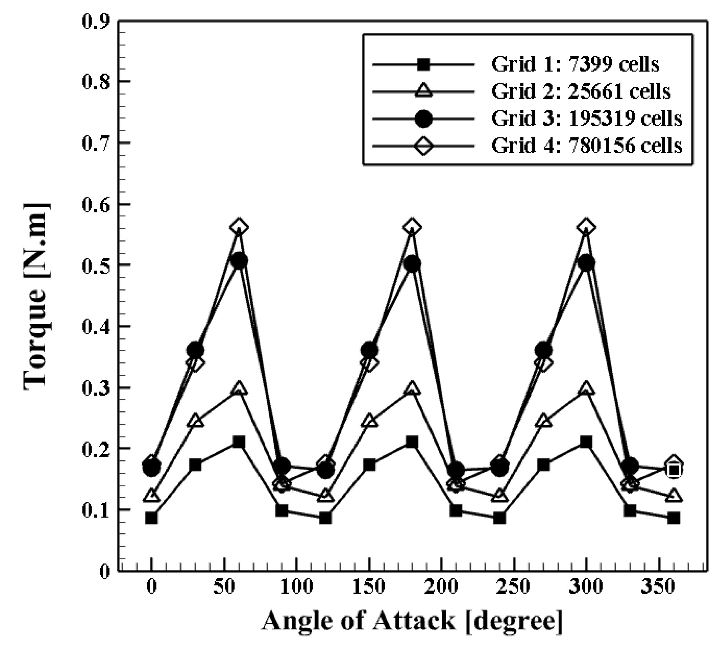
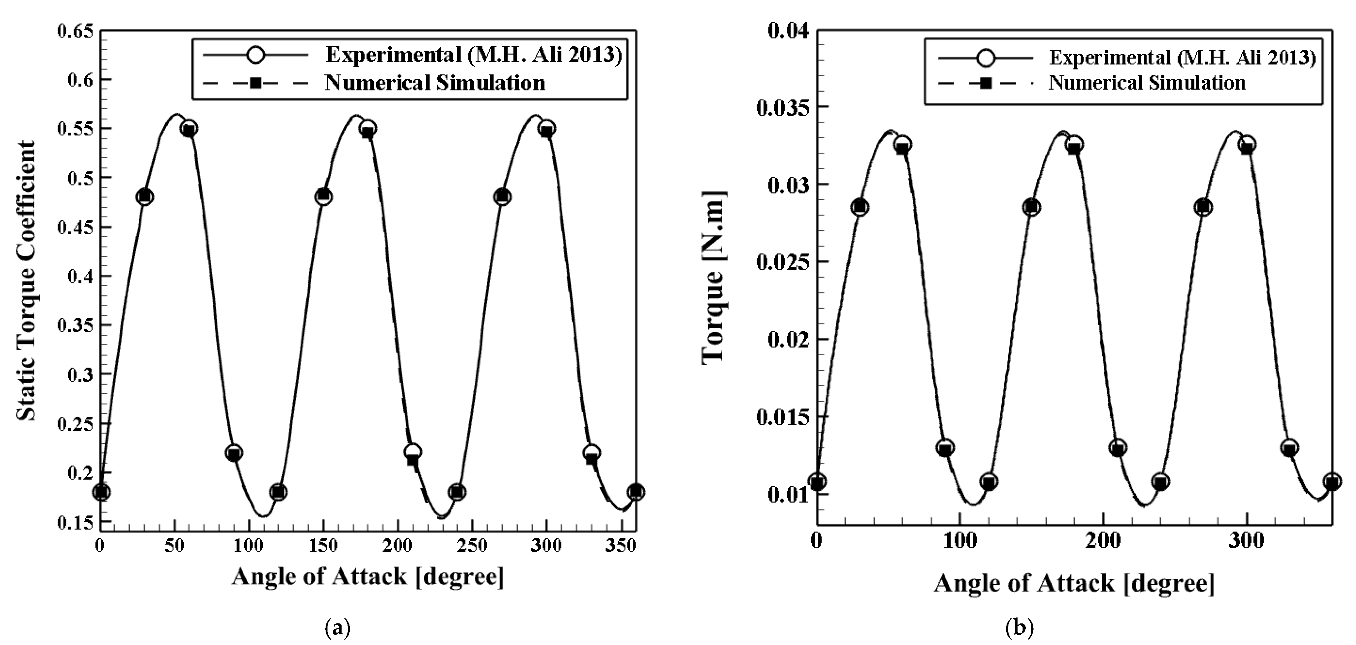
5.1. Grid Independence and Validation Analyses

Due to the importance of the fluid flow around the blades, the generated grid near the blades is smaller compared to other parts, and the governing equations can be solved more accurately. Due to the complexity of the geometry, triangular-type cells were generated here. The picture of the generated grids around the blades for each investigated computational domain is shown in Figure 3. The results of the grid-independency analysis are shown in Figure 4, and the produced torque is the control parameter. Four grids are considered here.
According to Figure 4, it can be seen that the differences between the obtained results for the third and fourth grids are not significant. So, to reduce the computational time, the third grid with 195,319 cells is used as the appropriate grid for numerical analysis.
The results of the experimental work of Ali [21] are used to validate the numerical model. The static torques coefficient values (as a dimensionless parameter) and torque values for the simple triple-blade Savonius rotor obtained in the wind tunnel at VWind = 5 m/s for different angles of attack in the laboratory are shown and compared with the presented numerical results in Figure 5.
The obtained results and the differences (errors) are listed in Table 2. Accordingly, the maximum error is 1.7%, showing the accuracy of the presented numerical method here. Moreover, Table 2 depicts that the errors for both parameters are positive and negative values because of possible numerical errors and possible low accuracy of the experimental setup.
As previously mentioned, in this study, a numerical analysis was performed on a two-dimensional model of the Savonius turbine equipped with a secondary blade and a slot on the main blade exactly behind the center of the secondary blade. At first, a simple triple-blade wind turbine Savonius rotor at different wind velocities of 3 to 6 m/s was examined. The simple triple-blade rotor output torque curve at various wind velocities of 3 to 6 m/s is shown in Figure 6. Obtained numerical results show that as the wind velocity increases, the output torque improves.
To realize better the behavior of the airflow around the simple triple-blade rotor, the velocity contours and velocity vectors at various angles of attack are demonstrated in Figure 7. The generated swirl flows around the rotors can be seen clearly for different angles of attack, which affect the amount of produced torque significantly.

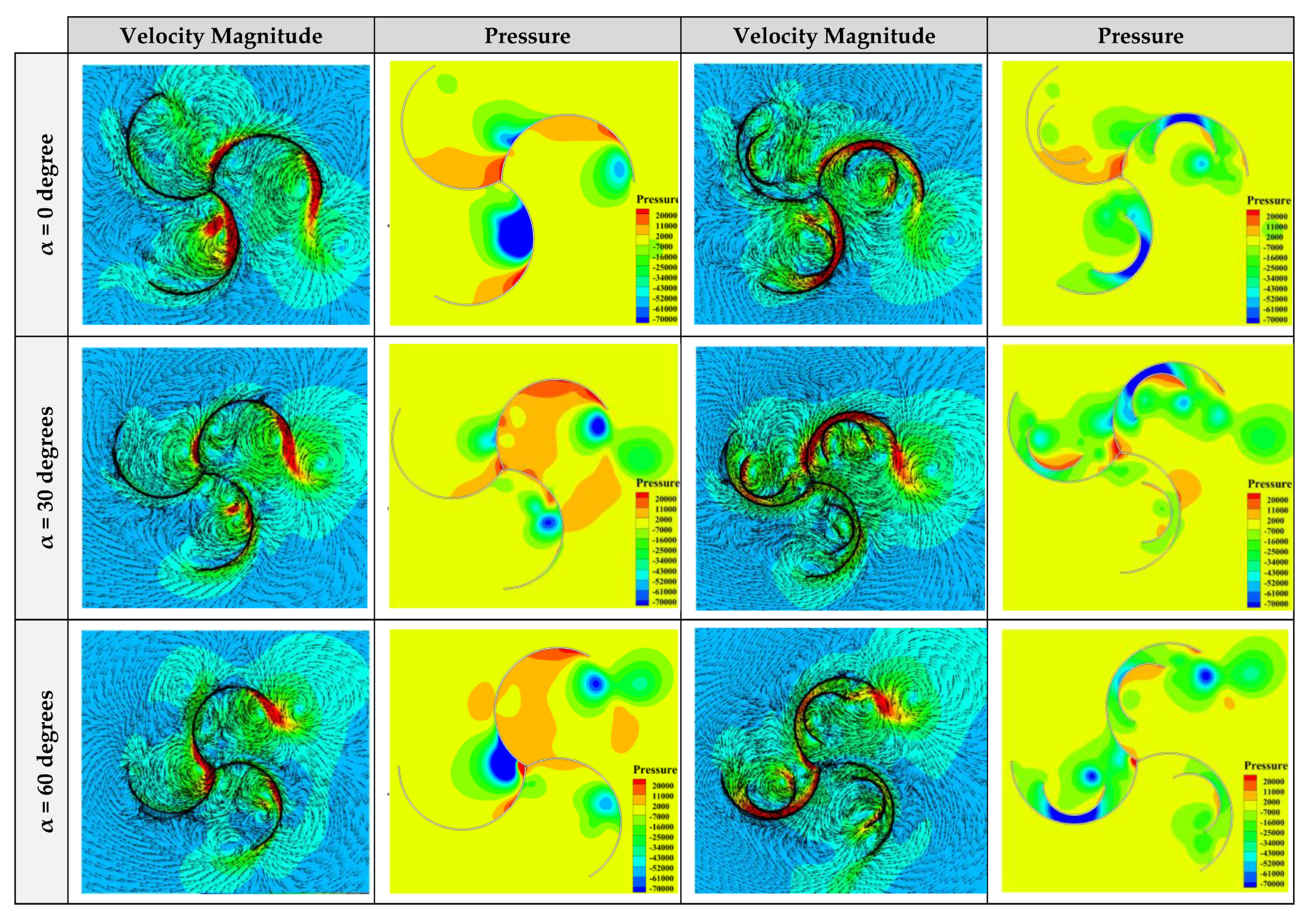
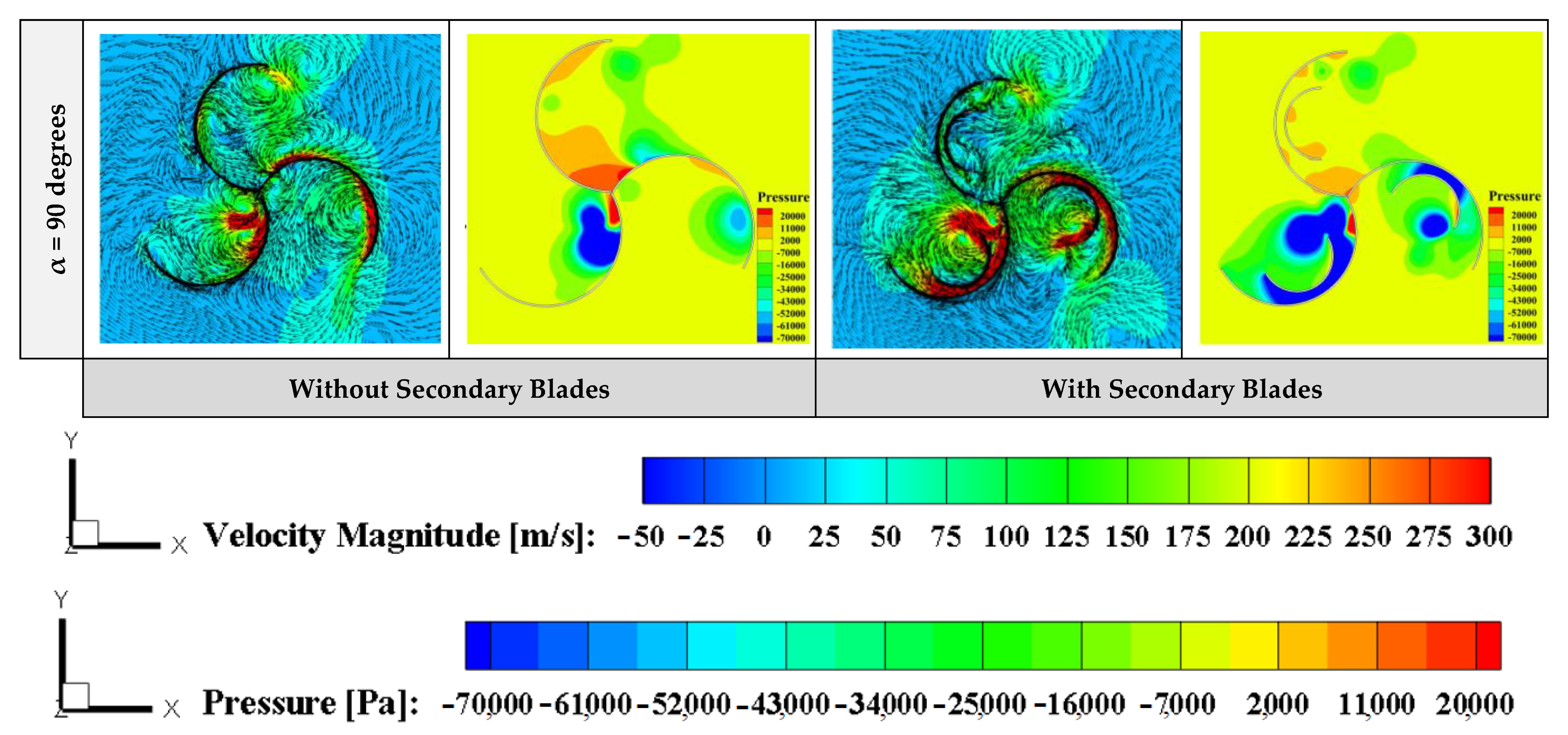
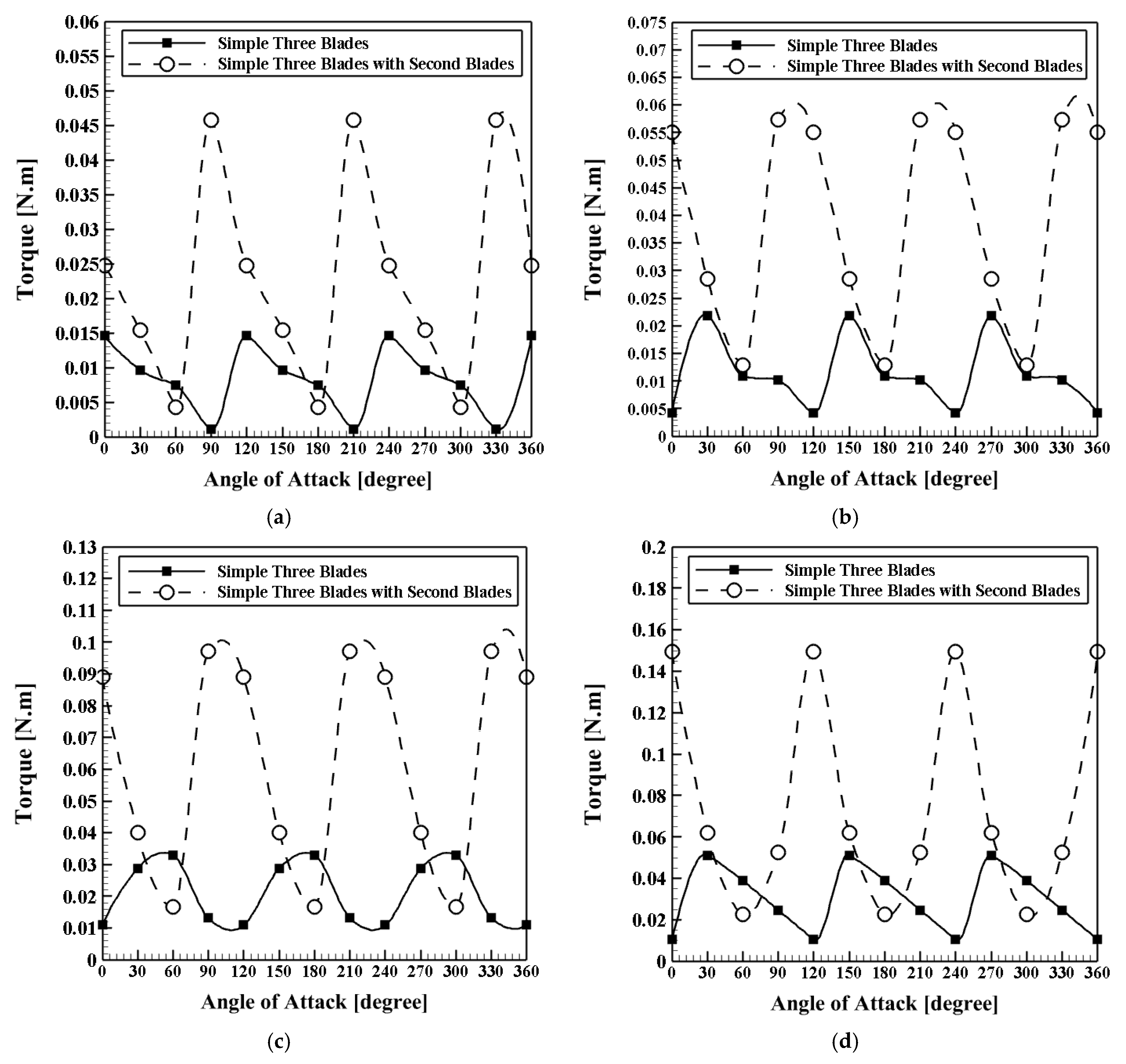
5.2. Impact of Adding Secondary Blades to the Main Blades

In this section, the effect of adding secondary blades to the main blades on the produced torque is examined numerically. Four various wind velocities, including 3, 4, 5, and 6 m/s, are considered and analyzed. The produced torque profiles versus different angles of attack for the case with secondary blades are shown in Figure 8.
By comparing the results of Figure 8 (the case with secondary blades) with the results of Figure 7 (the case without secondary blades), it can be concluded that adding secondary blades leads to significant growth in the produced torque by the rotors. For instance, it can be seen that at the wind velocity of 6 m/s, the maximum produced torque in the case with secondary blades is about 200% more than the case without secondary blades. In addition, to realize better the impact of adding secondary blades on the fluid flow around the turbine’s rotors, the contours of velocity magnitude and pressure are depicted in Figure 9 for various models at V = 5 m/s and h = 6 mm. Accordingly, it can be seen that adding secondary blades causes more velocity magnitude and swirl flows around the rotors, and consequently more torque can be produced around the proposed rotors.

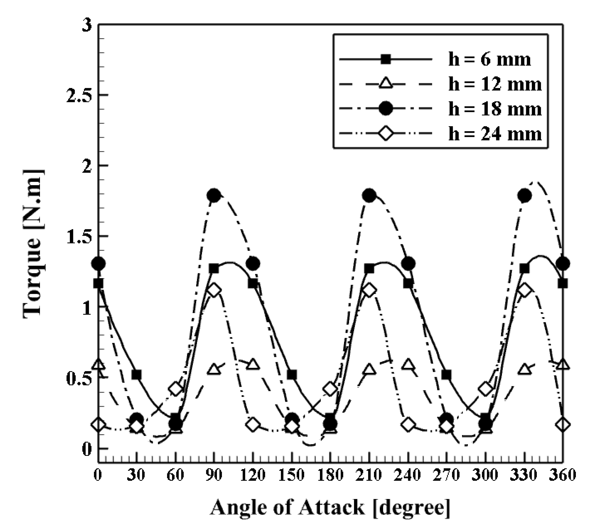
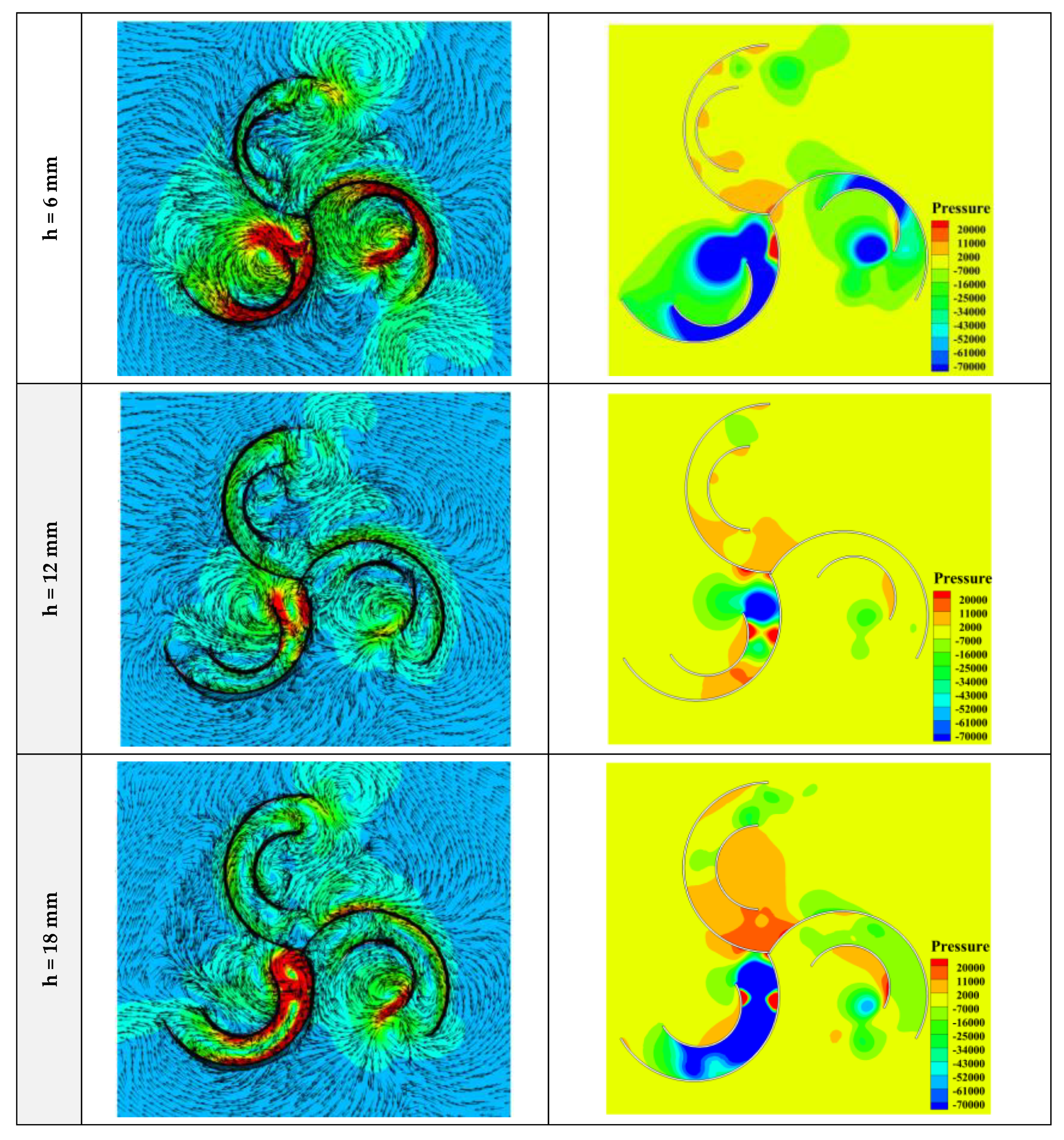
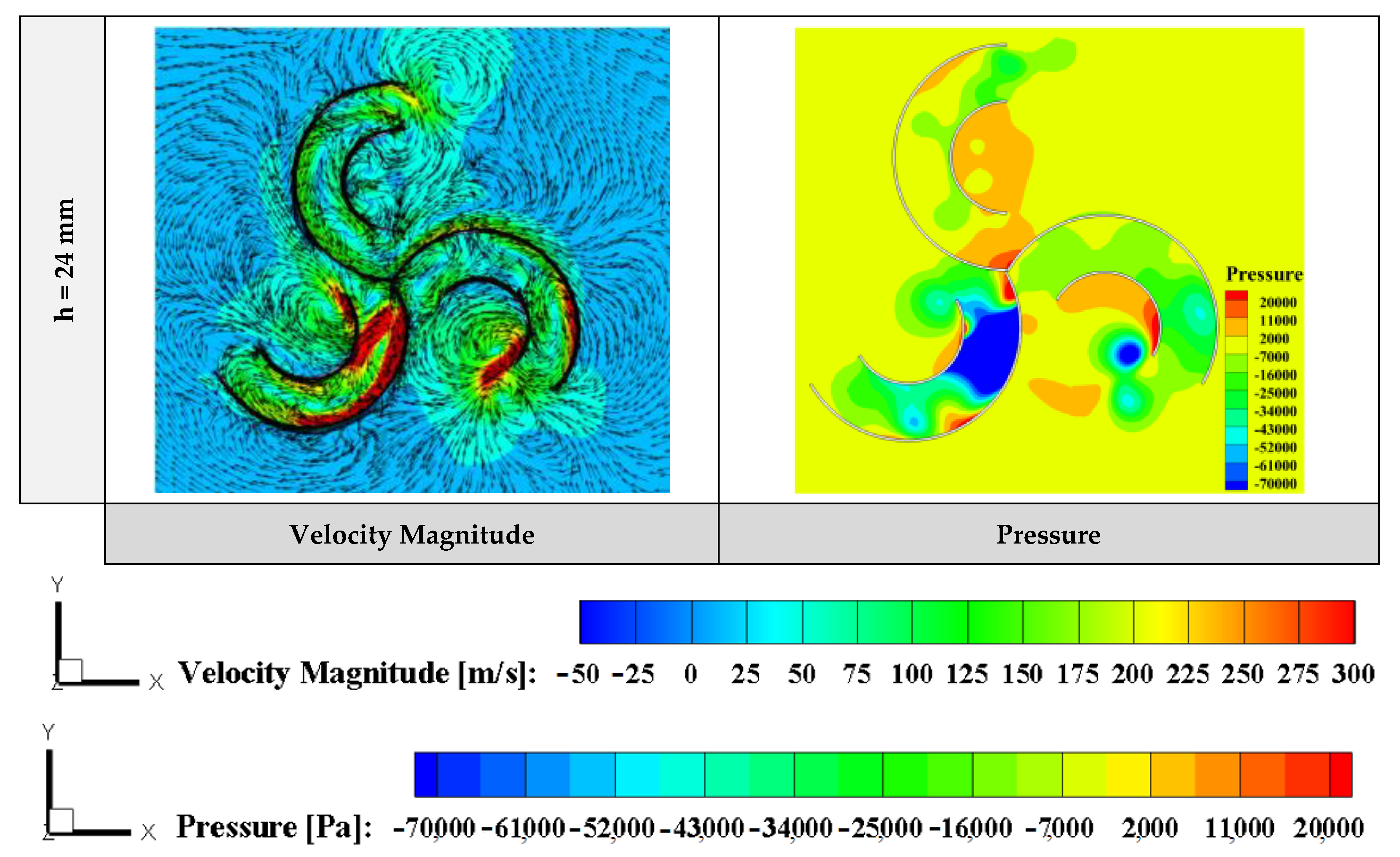
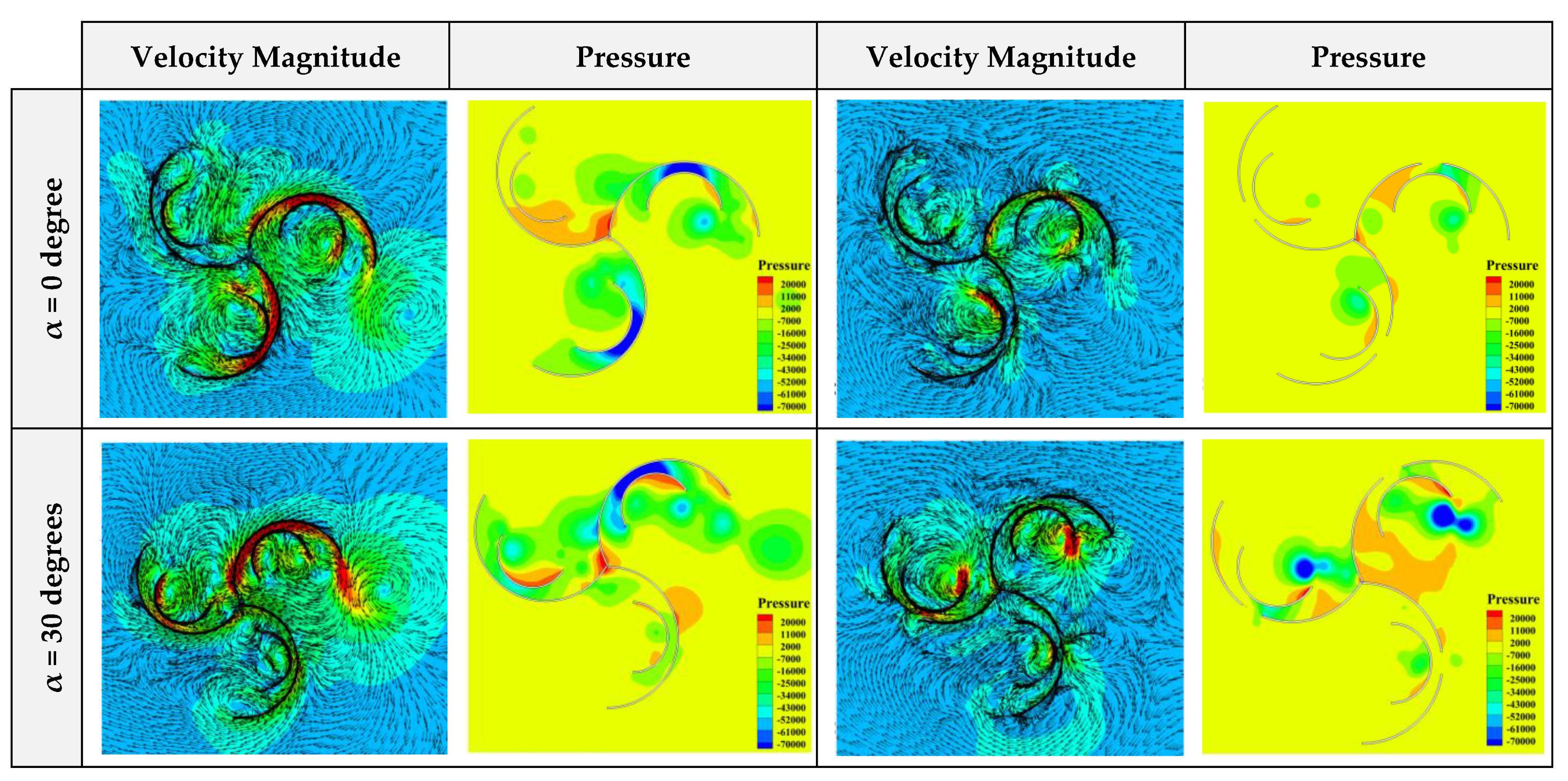
5.3. Impact of the Distance between the Main and Secondary Blades

In this section, the effect of the distance between the main and secondary (additional) blades on the produced torque is investigated. Four various distances, including 6, 12, 18, and 24 mm, are considered and analyzed. The present study evaluates the amount of production torque at different distances of h = 6, 12, 18, and 24 mm at a constant wind velocity of 5 m/s. Figure 10 shows the production torque curve versus the various angles of attack for various models. According to the display of the output torque curve shown in Figure 10, it can be concluded that at an angle of zero degrees, the highest torque is observed at the distance of h = 6 mm. At an angle of 60 degrees, the maximum torque is produced when the distance is 24 mm. At a 90-degree angle of attack, the maximum torque is achieved when the distance is 18 mm. Finally, the area below the curve diagram shows that by creating a distance of 6 mm, the maximum output torque (and consequently power) is produced for all angles.
The velocity and pressure contours are shown in Figure 11. Accordingly, it can be seen that as the distance between the main and additional blades increases, the velocity magnitude between the main and additional blades decreases. Moreover, the vortex and rotational flows behind the secondary blades produce negative torque. The shorter the distance, the more negative is the pressure gradient obtained and consequently more fluid flows upon the blades, illustrated by pressure contours in Figure 11 in which the amount of pressure gradient is well represented.
The output torque curve of the simple Savonius turbine is compared with the Savonius rotor with an additional blade (as secondary blades) at a distance of h = 6 mm from the main blade at four wind velocities of VWind = 3, 4, 5, and 6 m/s (Figure 12). The addition of a blade within the turbine rotor increases the area under the output torque diagram, and consequently, produced power (torque). This performance improvement was achieved at all four studied wind velocities. At VWind = 3 m/s and an angle of zero degrees, the output torque improved by about 66%. At a 30-degree angle, the output torque improves by about 70%. At 60 degrees, the torque decreases by about 47%. At a 90-degree angle with the added blade, the torque increases from 0.001 to 0.0462. At a wind velocity of VWind = 4 m/s and an angle of zero degrees, the torque rises from about 0.0048 to 0.055. Output torque improvement percentages of 29%, 5.0%, and 320% are obtained at an angle of 30 degrees, 60 degrees, and 90 degrees, respectively. At a wind velocity of VWind = 5 m/s and an angle of zero degrees, the output torque increased from about 0.009 to 0.088, and at an angle of 30 degrees, an improvement of about 33% was achieved. However, at a 60-degree angle, the values vary, and with the secondary blade, the output torque decreases by almost 125%. For a 90-degree angle, nearly 550 percent improvement was achieved. Additional torque increased by about ten times at a wind velocity of VWind = 6 m/s and an angle of zero degrees. At an angle of 30 degrees, the output torque improved by about 17%. The result was reversed at an angle of 60 degrees, and the torque was reduced by about 71%. At a 90-degree angle, about 98% improvement was seen in the output torque.

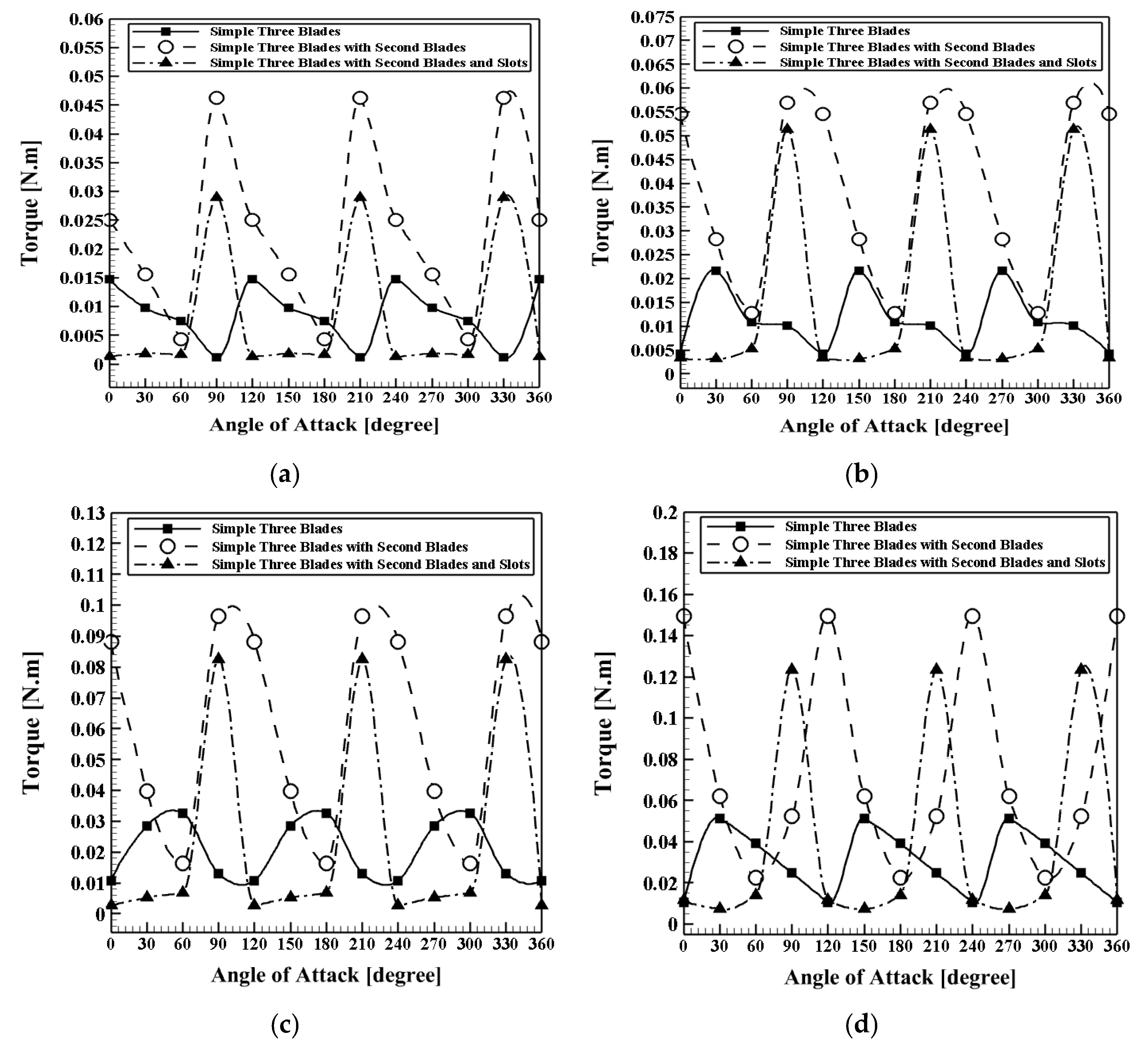
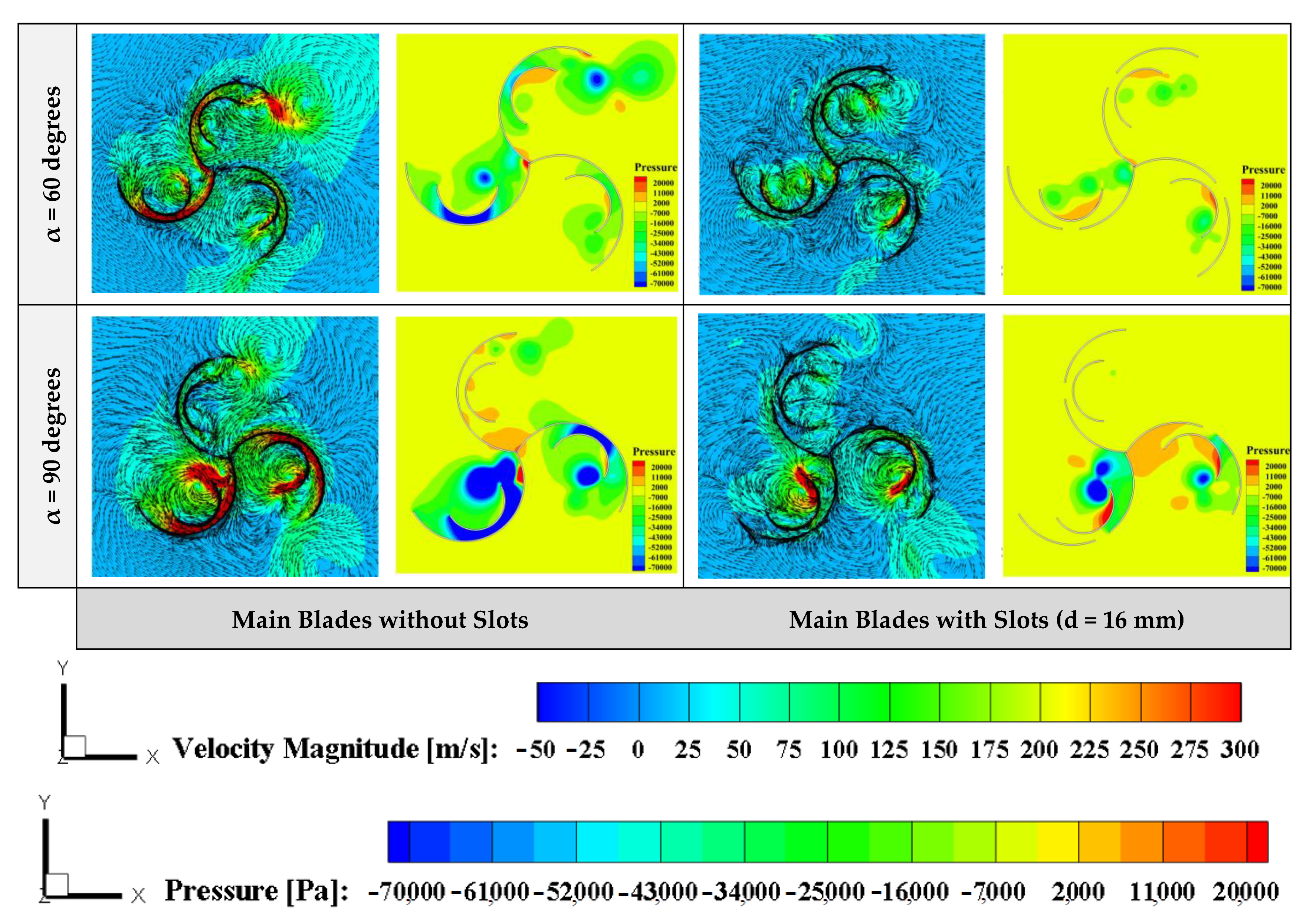
5.4. Impact of Adding Secondary Blades with Slots in the Centerline of the Main Blades

In the present section, the influence of the slot in the secondary blade on produced torque is studied and analyzed. This slot has two functions; first, it avoids the negative torque caused by the clash of reverse flows from the outer blade to the inner one. Second, due to the negative pressure existing behind the blade, the flow sinks into the slot and induces an extra torque. The outer blade’s slot width d and the intervals between blades h are the factors that influence the rotor’s torque output. The width of slot d is the studied parameter here. Accordingly, four different widths of the main blade’s slot, including d = 4, 8, 12, and 16 mm, are considered. Furthermore, the simulations are performed for four different wind velocities, including VWind = 3, 4, 5, and 6 m/s. Furthermore, the produced torque versus various models and wind velocities are depicted in Figure 13. Accordingly, it can be seen that among the range of the considered wind velocities VWind = 3–6 m/s, the maximum produced torque of case VWind = 6 m/s is the highest in all studied cases and the lowest one belongs to VWind = 3 m/s. Contours of velocity magnitude and pressure for two different cases including with and without slots and various angles of attack at VWind = 5 m/s, h = 6 mm, and d = 16 mm are illustrated in Figure 14.
Figure 14 shows that because of increasing the contraction area between the blades and wind flows, and also the contraction of the flow between the two blades (main and secondary ones), the pressure increases, and as a result, the produced torque rises as well. Actually, the existence of this slot brings with it several functions. First, the fluid flow entering the back of the main blade is associated with some return flows. These reverse flows hit the back of the secondary blade, producing negative torque. Second, this slot partially prevents the return flow and thus the production of negative torque. Third, the current entering the back of the inner blade is pulled into the slot created by the pressure behind the blade on the main blade, creating an additional torque. Fourth, the width of the slot can have a significant effect on the output. Therefore, 4, 8, 12, and 16 mm were studied for different slot widths d. Figure 15 displays the effect of the width of the slot on the output torque for different values of d = 4, 8, 12, and 16 mm and various wind velocities.
Figure 15 illustrates that for all considered widths of the slot, growth in the wind velocity leads to an augmentation in the produced torque. The profiles of the produced torque versus the angle of attack for various slot widths and different wind velocities are presented in Figure 16.
According to Figure 16, the output torque values were improved by increasing the slot’s width from d = 4 mm to d = 16 mm at an angle of 90 degrees. The results show that the maximum output torque is obtained if the slot’s width value is equal to d = 16 mm.

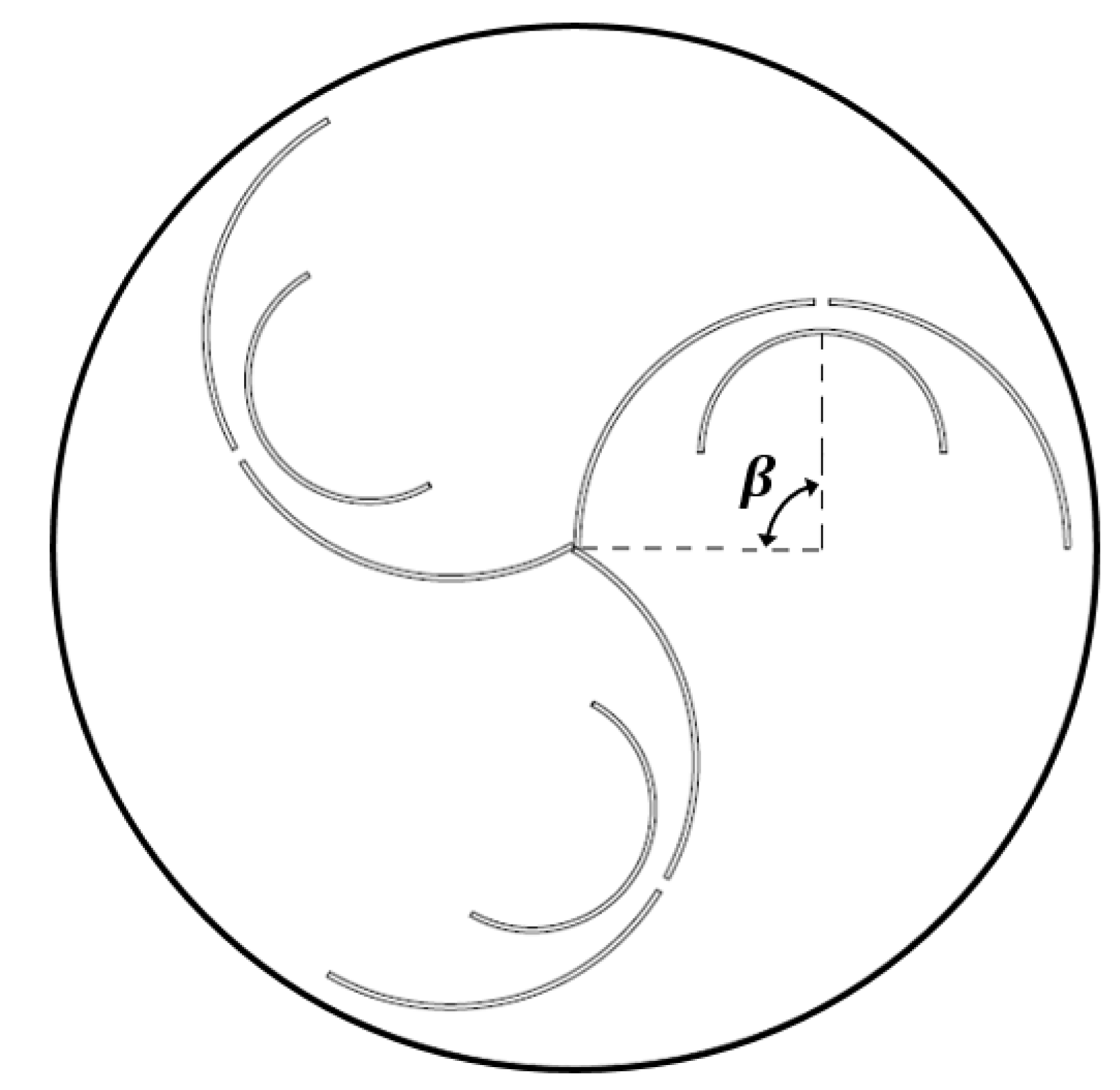
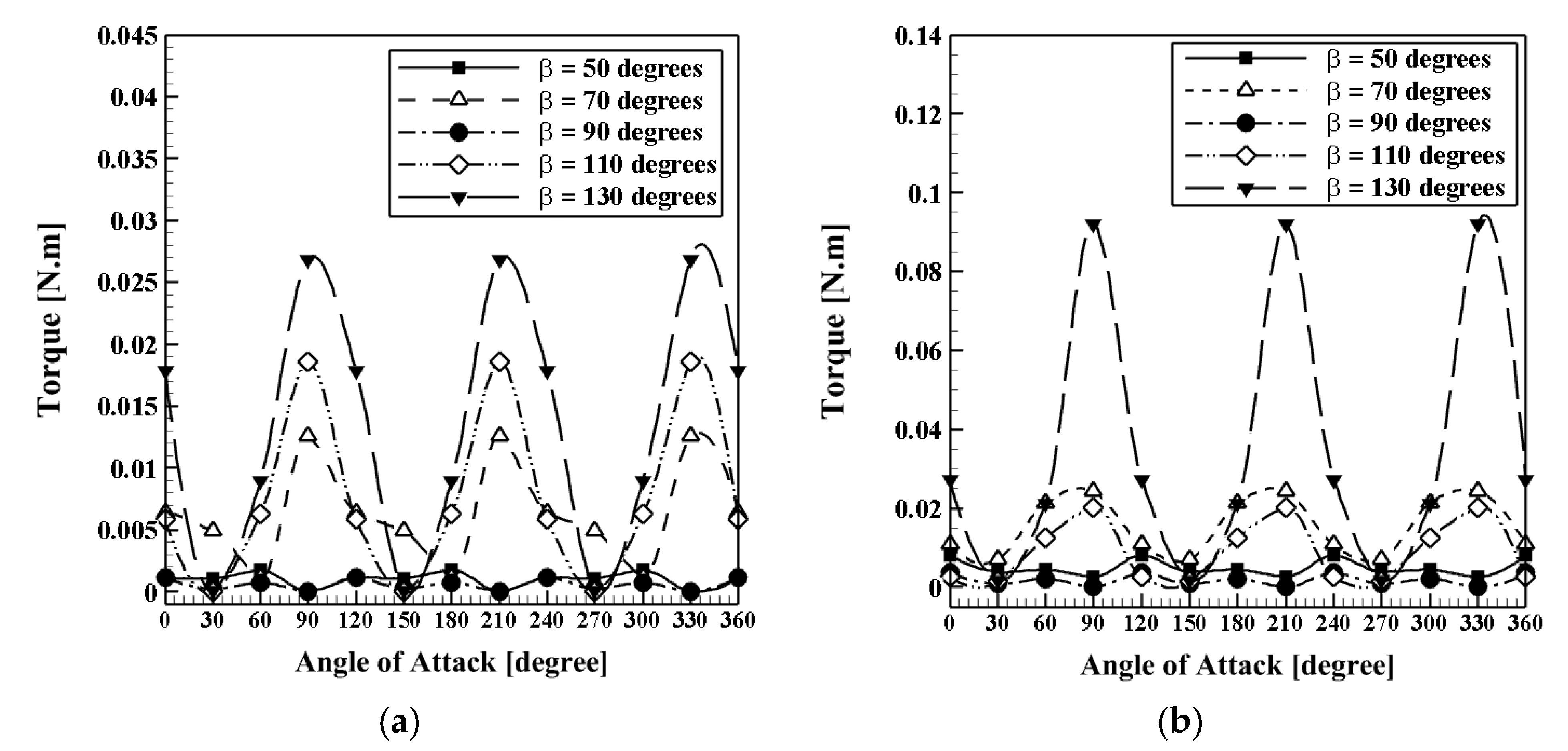
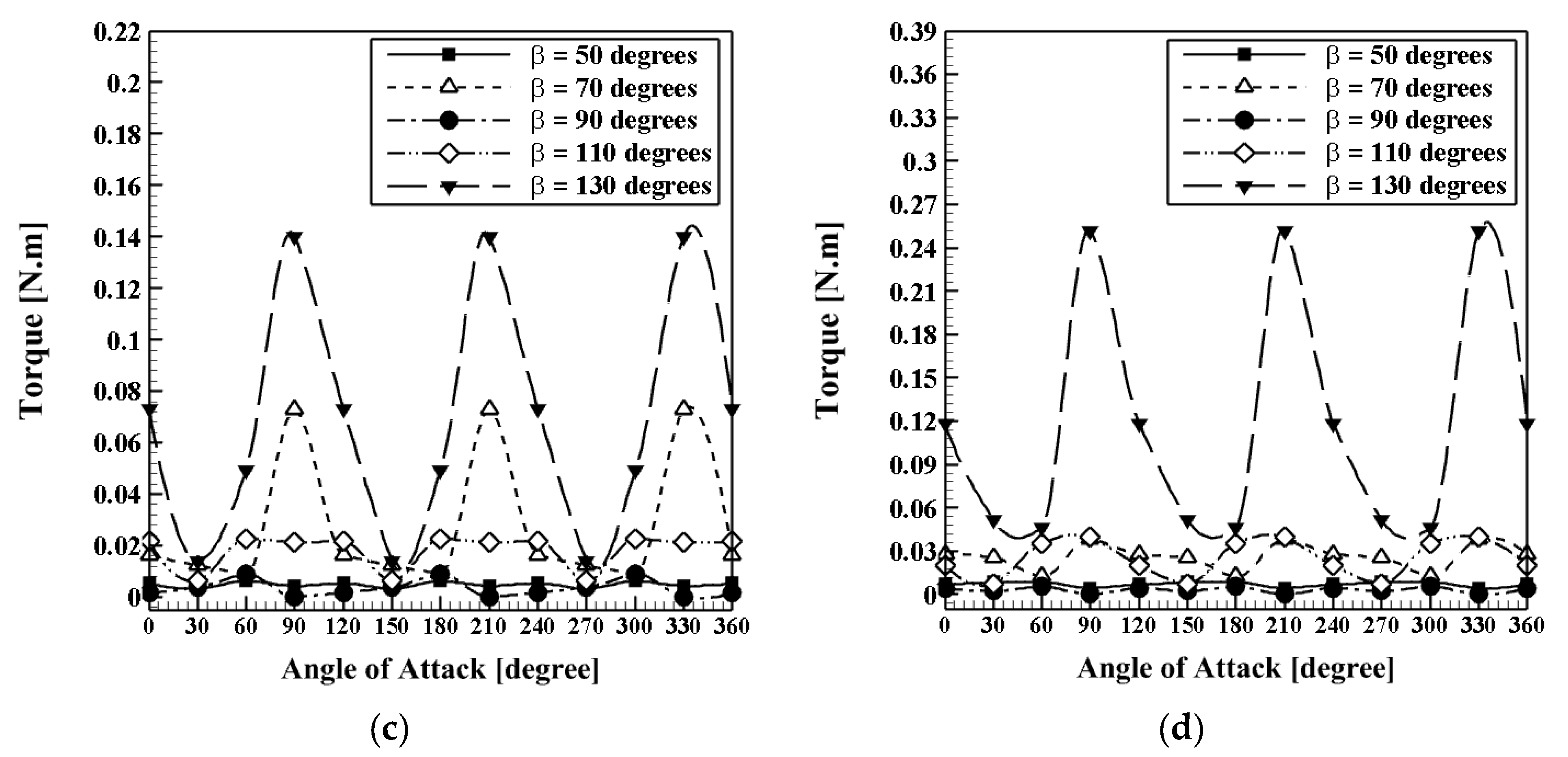
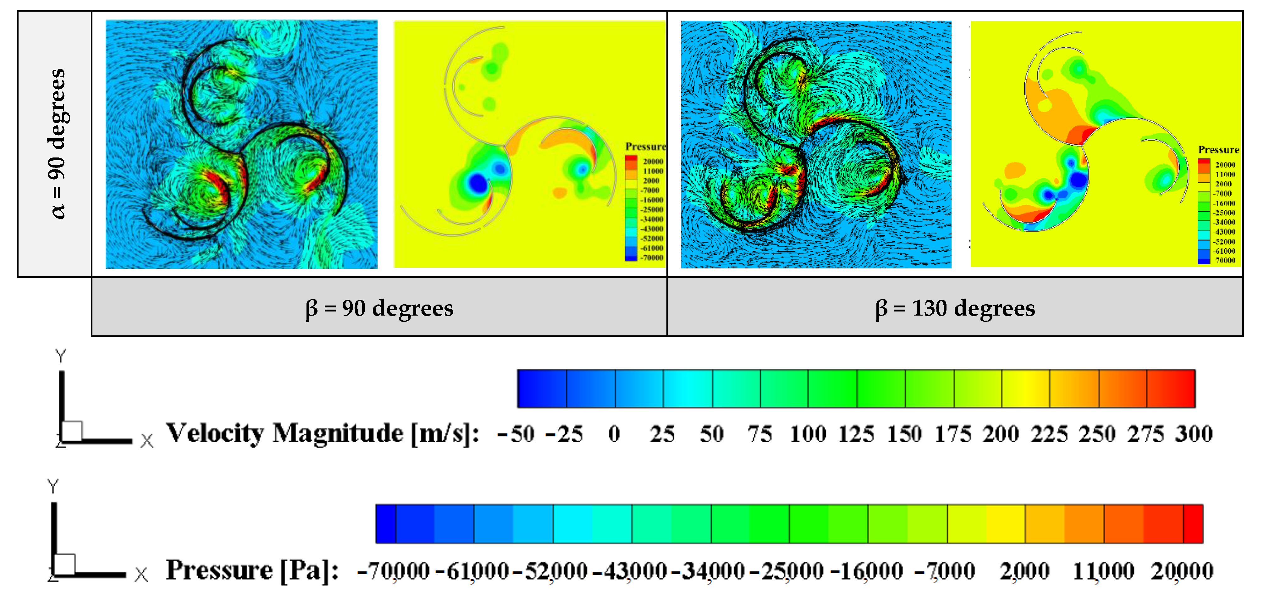
5.5. Impact of the Angular Position (β) of the Secondary Blades and Slots

In the present section, the influence of the secondary blades and slots’ angular position on produced torque is studied and analyzed. The studied geometry of the computational domain here with various angular position angles β of the secondary blades and slots at h = 6 mm and d = 4 mm is illustrated in Figure 17. Accordingly, five different slots and secondary blades’ angular positions, including β = 50, 70, 90, 110, and 130 degrees, are considered here. Furthermore, the simulations are performed for four different wind velocities, including 3, 4, 5, and 6 m/s. It is worth mentioning that in all considered cases, the slots are placed exactly behind the centerline of the secondary blades in any angular position.
Furthermore, the produced torque versus various models and wind velocities are depicted in Figure 18. Accordingly, it can be seen that the maximum produced torque in the case β = 130 degrees is the highest for all studied wind velocities, and the lowest one belongs to the cases β = 50 and 90 degrees with low differences in all studied wind velocities. Figure 18a shows that at VWind = 3 m/s, as the slots and secondary blade angular position (β) increase from 50 to 130 degrees (160% growth), the maximum and minimum produced torques belong to cases β = 130 degrees (at α = 90 degrees) and β = 90 degrees (at α = 90 degrees), respectively. In addition, at Vwind = 3 m/s, the maximum produced torque in the case β = 130 degrees is 42.11 and 107.7% more than the maximum produced torques in cases β = 110 and 70 degrees, respectively. Furthermore, according to Figure 18b, at Vwind = 4 m/s, by increasing the secondary blade’s angular position by 160% from β = 50 degrees, the cases β = 130 degrees (at α = 90 degrees) and β = 90 degrees (at α = 30 degrees) show the highest and lowest produced torques, respectively. At Vwind = 4 m/s, the maximum produced torque in case β = 130 degrees is 350 and 260% more than the maximum produced torques in cases β = 110 and 70 degrees, respectively (Figure 18b). In addition, at Vwind = 5 m/s, 160% growth in the slots and secondary blade’s angular position (β = 50 to 130 degrees) cause the cases β = 130 degrees (at α = 0 degree) and β = 90 degrees (at α = 90 degrees) to present maximum and minimum produced torques, respectively. Moreover, at Vwind = 5 m/s, the maximum produced torque in the case β = 130 degrees is 86.67 and 600% more than the maximum produced torques in cases β = 70 and 110 degrees, respectively (Figure 18c). In addition, at Vwind = 6 m/s, 160% growth in the secondary blade’s angular position (β = 50 to 130 degrees) causes the cases β = 130 degrees (at α = 90 degrees) and β = 90 degrees (at α = 90 degrees) to present maximum and minimum produced torques, respectively, Moreover, at Vwind = 6 m/s, the maximum produced torque in the case β = 130 degrees is 525% more than the maximum produced torques in the case β = 70 degrees and the difference between cases β = 70 and 110 degrees is very minor (Figure 18d).
To realize better the influence of the slots and secondary blade’s angular position β on fluid flow and pressure distribution, the contours of velocity magnitude and pressure are shown in Figure 19. Accordingly, it can be seen that by increasing the slots and secondary blade’s angular position (160% growth from β = 50 to 130 degrees), the fluid confinement area between the main and secondary blades increases, which leads to augmentation in the velocity magnitude (larger red region in the case β = 130 degrees in comparison with the case β = 90 degrees), and consequently, more torque can be produced. Furthermore, according to pressure contours, it is shown that in the case of β = 130 degrees, the blue region with negative pressure is larger than in the case β = 90 degrees, meaning that the pressure differences between the two sides of the main blades become more significant and lead to more produced torque.

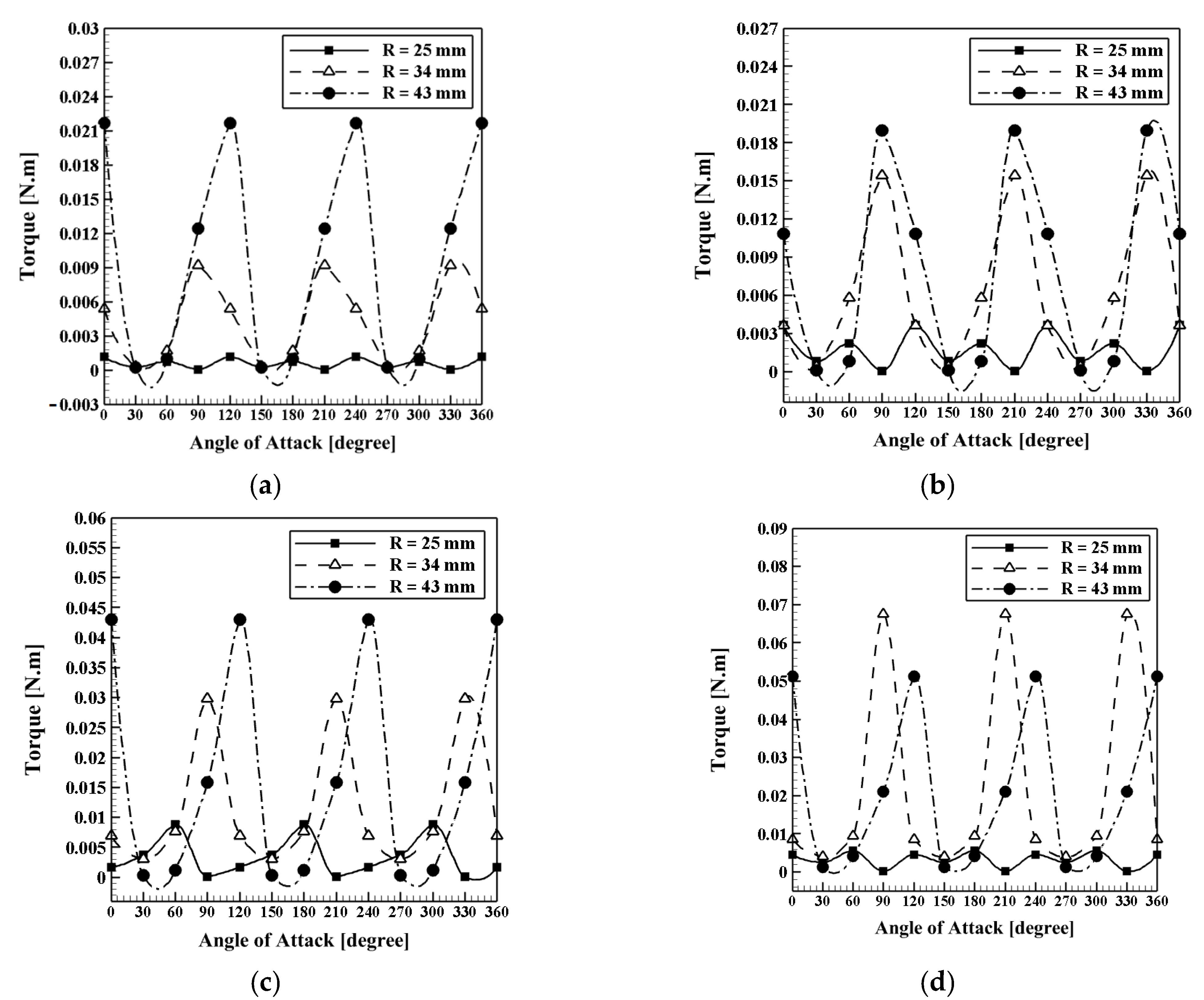
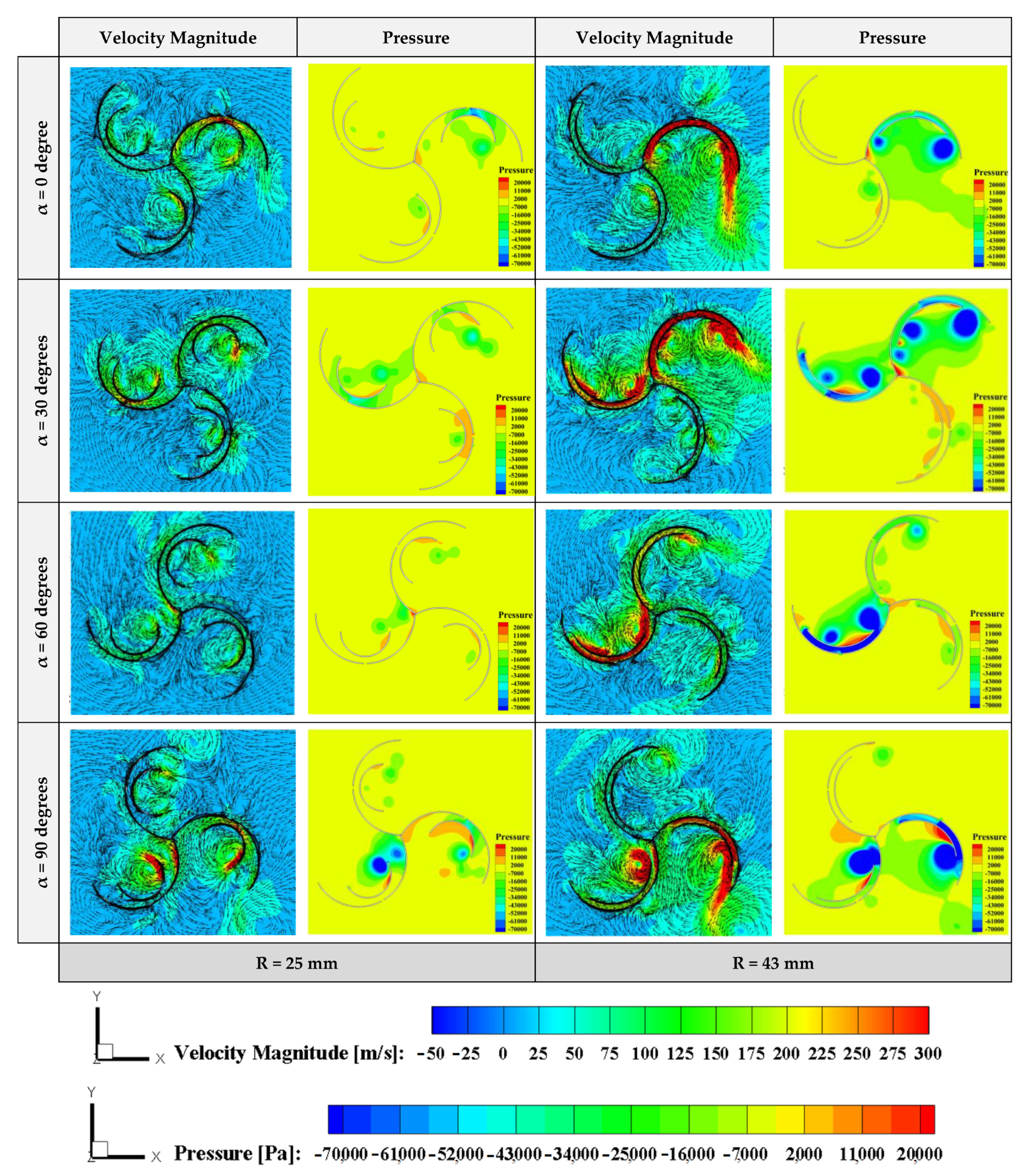
5.6. Impact of the Secondary Blade’s Profile (Secondary Blade’s Radius (R))

In the present section, the influence of the secondary blade’s profile on produced torque is investigated and analyzed. The studied geometry of the computational domain with various profiles of the secondary blade at β = 90 degrees, h = 6 mm, and d = 4 mm is illustrated in Figure 20. Accordingly, three different values for parameter R as the secondary blade’s radius, including R = 25, 34, and 43 mm, are considered here. The simulations are performed for four different wind velocities, including 3, 4, 5, and 6 m/s. The produced torque versus various models and wind velocities are depicted in Figure 21.
Figure 21a shows that at VWind = 3 m/s, as the secondary blade’s radius increases from R = 25 to 43 mm (72% growth), the maximum and minimum produced torques belong to cases R = 43 mm (at α = 0 degree) and R = 25 mm (at α = 90 degrees), respectively. Moreover, at VWind = 3 m/s, the maximum produced torque of case R = 43 mm is 1863 and 137.3% more than the maximum produced torques at R = 25 and 34 mm, respectively. Furthermore, according to Figure 21b, at Vwind = 4 m/s, increasing the secondary blade’s radius by 72% from the cases R = 43 mm (at α = 90 degrees) and R = 25 mm (at α = 30 degrees) show the highest and lowest produced torques, respectively. Thus, at VWind = 4 m/s, the maximum produced torque in case R = 43 mm is 416.6 and 23.17% more than the maximum produced torques in cases R = 25 and 34 mm, respectively (Figure 21b). Furthermore, at VWind = 5 m/s, 72% growth in the secondary blade’s radius (R = 25 to 43 mm) causes the cases R = 43 mm (at α = 0 degree) and R = 25 mm (at α = 60 degrees) to present maximum and minimum produced torques, respectively, Moreover, at VWind = 5 m/s, the maximum produced torque of case R = 43 mm is 384.61 and 45% more than the maximum produced torques of cases R = 25 and 34 mm, respectively (Figure 21c). Furthermore, at VWind = 6 m/s, 72% growth in the secondary blade’s radius (R = 25 to 43 mm) causes the cases R = 43 mm (at α = 0 degree) and R = 25 mm (at α = 60 degrees) to present maximum and minimum produced torques, respectively, Moreover, at VWind = 6 m/s, the maximum produced torque in case R = 43 mm is 384.61 and 45% more than the maximum produced torques of cases R = 25 and 34 mm, respectively (Figure 21d).
To realize better the effect of the secondary blade’s radius on the fluid flow and pressure distribution, the contours of velocity magnitude and pressure are shown in Figure 22. Accordingly, it can be seen that by increasing the secondary blade radius (here 72% from 25 to 43 mm), the fluid confinement area between the main and secondary blades increases, which leads to augmentation in the velocity magnitude (larger red region in case R = 43 mm in comparison with case R = 25 mm). Consequently, more torque can be produced. Furthermore, according to pressure contours, it is shown that in the case of R = 43 mm, the blue region with negative pressure is larger than in the case R = 25 mm, which means that the pressure differences between the two sides of the main blades become more and lead to more produced torque.

6. Conclusions and Future Scope

In this study, a numerical analysis was performed on the two-dimensional model of the vertical turbine of the triple-blade Savonius vertical axis equipped with additional blades. Numerical simulation was applied by the commercial code ANSYS FLUENT. The reference model of rotational coordinates was used to analyze the flow turbulence of the k-ε standard turbulent model and simulate the two-dimensional rotor rotation in the steady state. Furthermore, the effect of the position (distance) of the main blade and the secondary blade and the wind velocity on the performance of the triple-blade Savonius turbine was analyzed and evaluated. The following results were obtained:
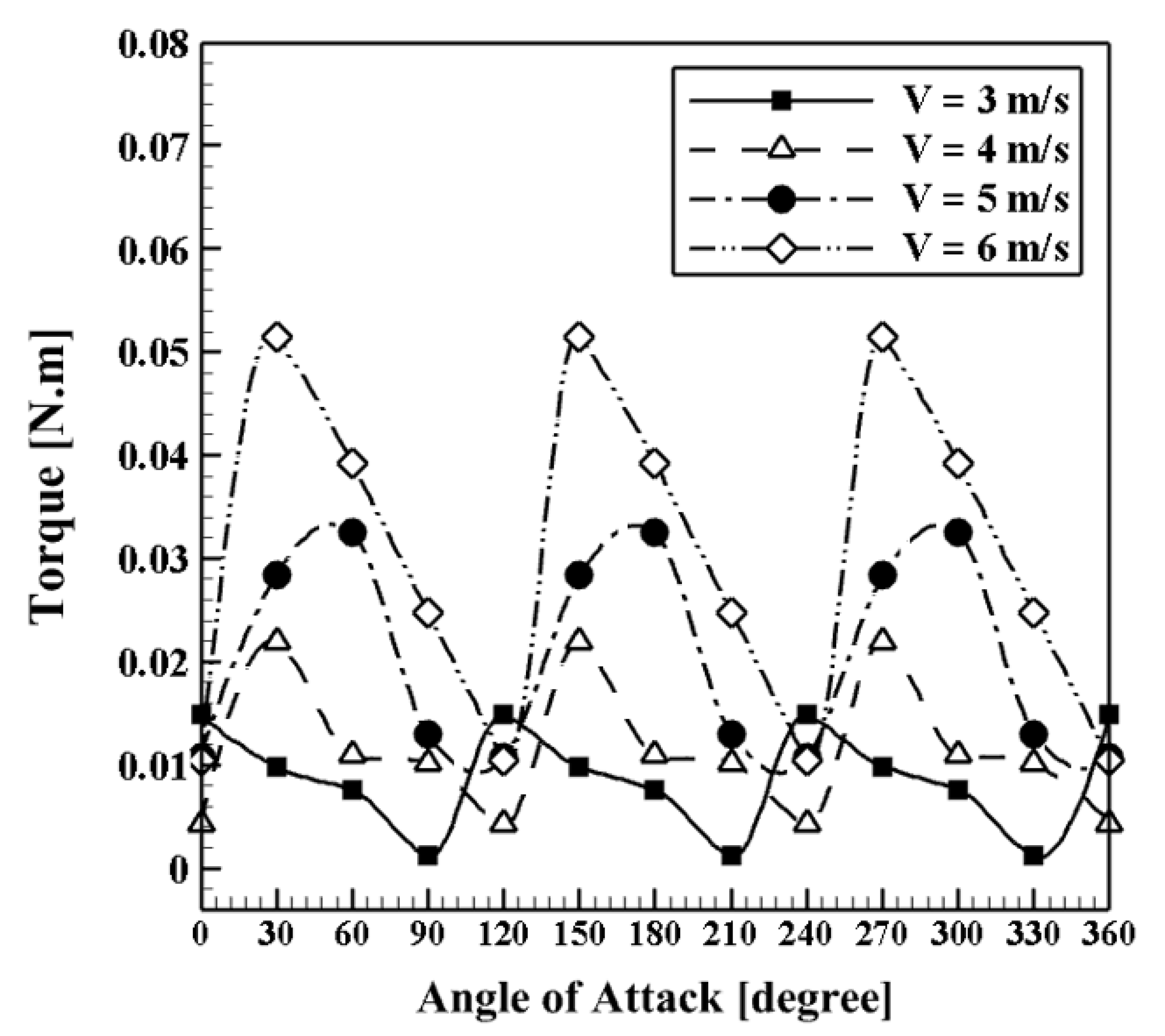
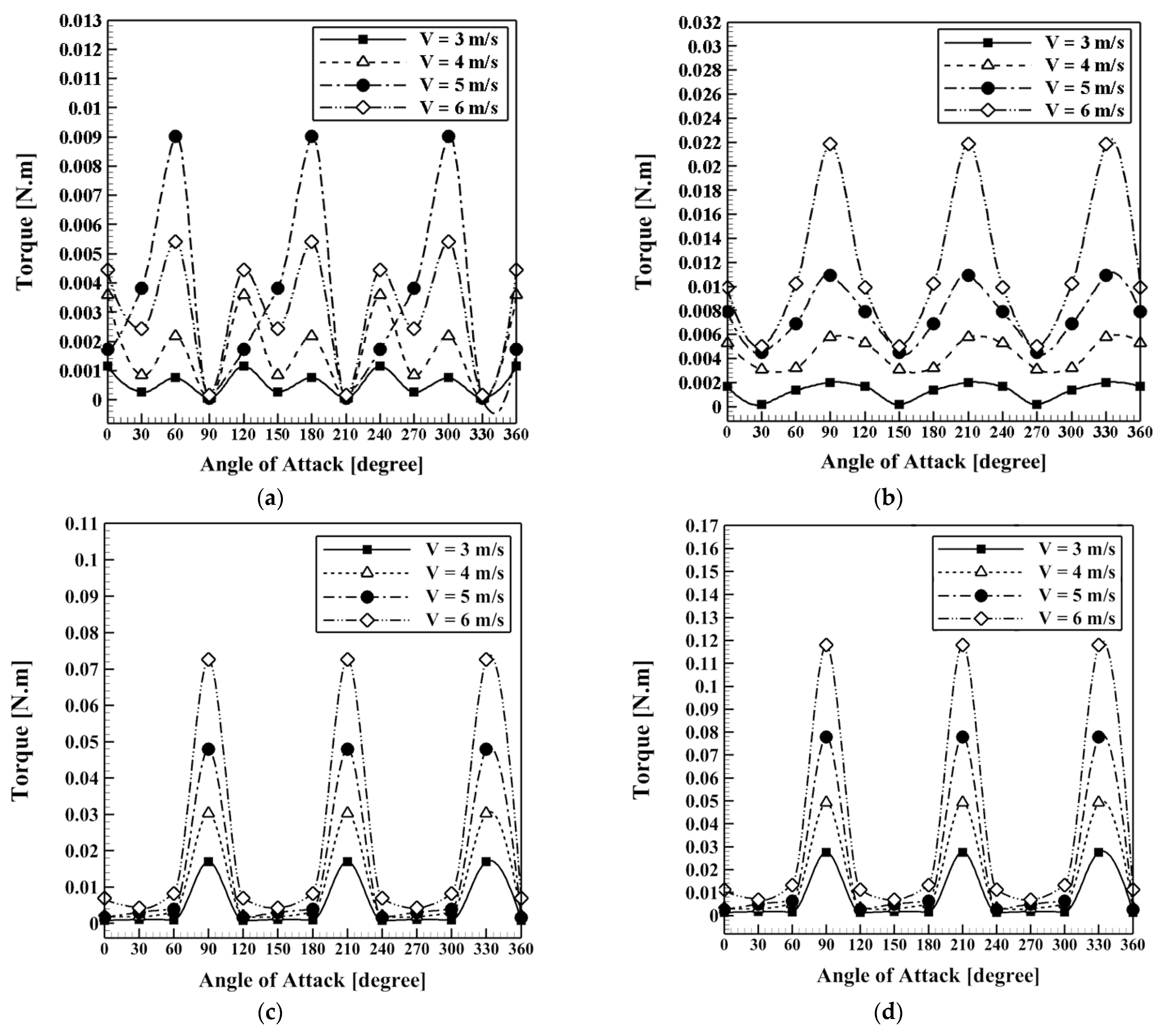
  • A 50 mm-diameter simple triple-blade Savonius turbine with a wind velocity of 5 m/s was tested at various wind velocities of 3, 4, and 6 m/s. The results show that as the wind velocity increases, the output torque improves.
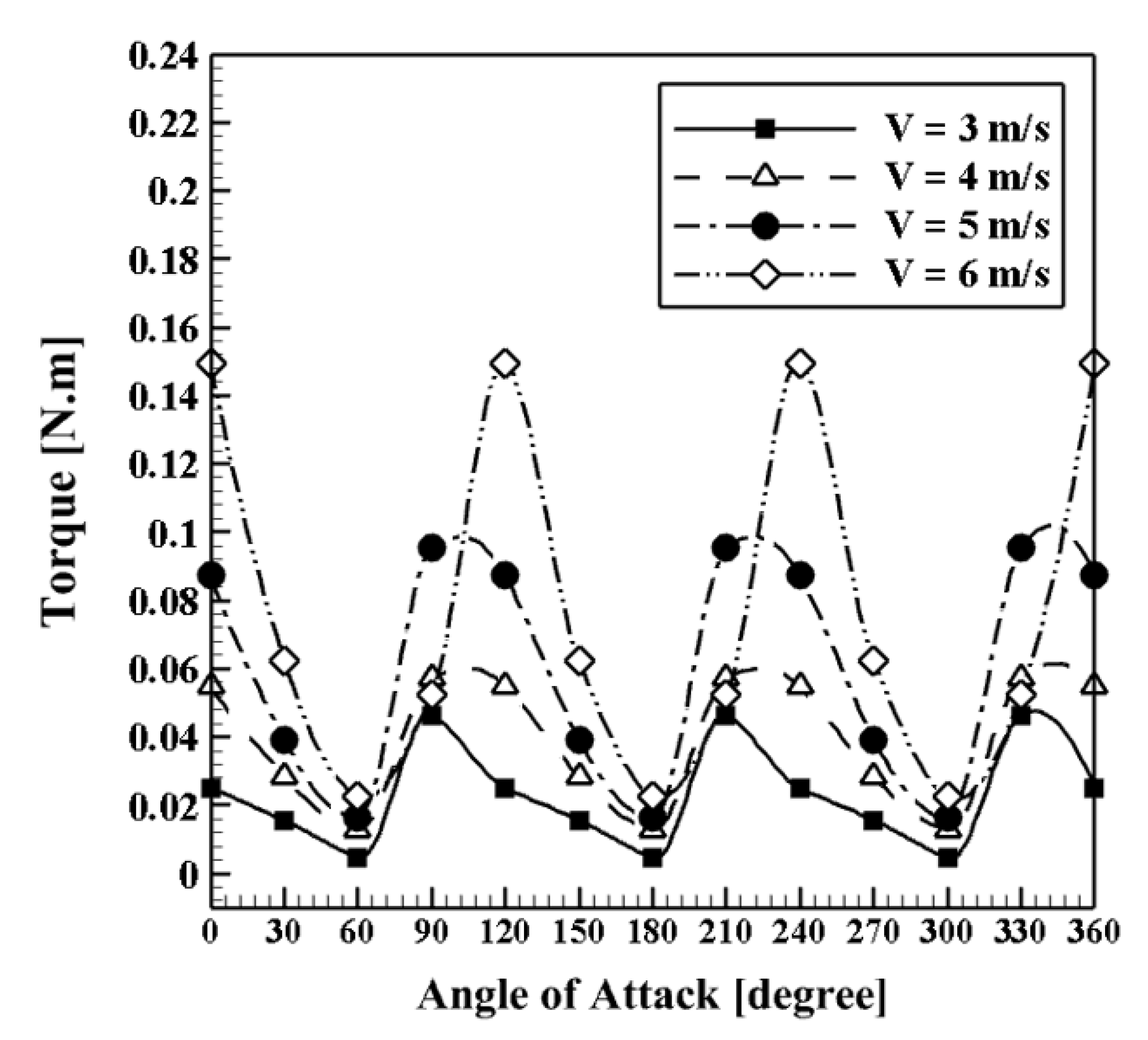
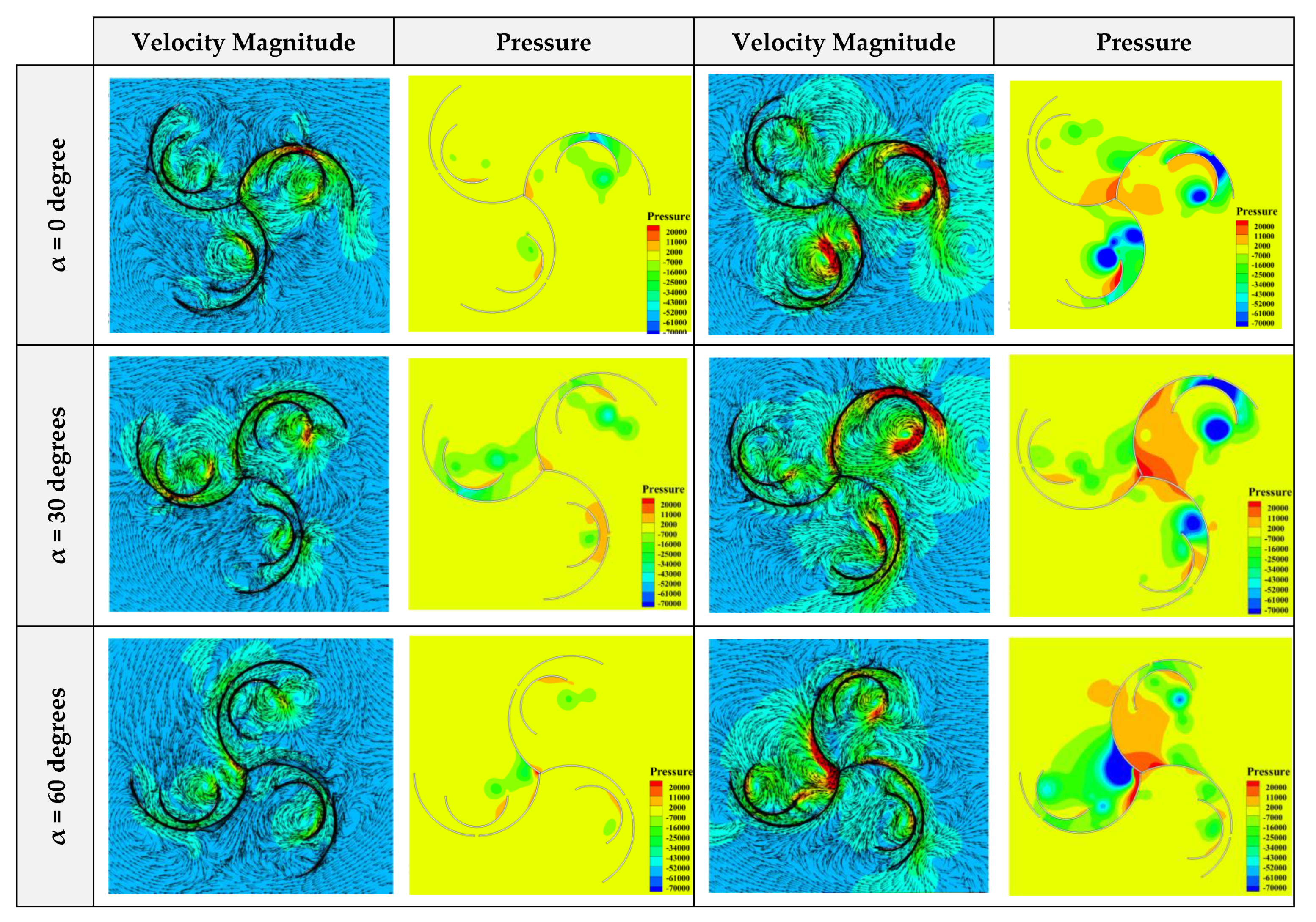
  • For a wind velocity of 5 m/s, the maximum output torque, unlike the simple triple-blade Savonius rotor obtained at 30 and 60 degrees, was obtained at zero and 90 degrees. Furthermore, the results showed that the best performance of the turbine was achieved when the secondary blade was located at a distance of 6 mm.
  • The output torque curve and the numerical results show that the area below the output torque diagram increased and turbine performance was enhanced despite the secondary blade. For example, at a velocity of 5 m/s and an angle of zero degrees, the output torque increased from about 0.009 to 0.088 Nm, and at an angle of 30 degrees, an improvement of about 33% was achieved. However, at 60 degrees, the values are different, and despite the secondary blade, the output torque decreases by nearly 125%. For a 90-degree angle, about 550% improvement was achieved.
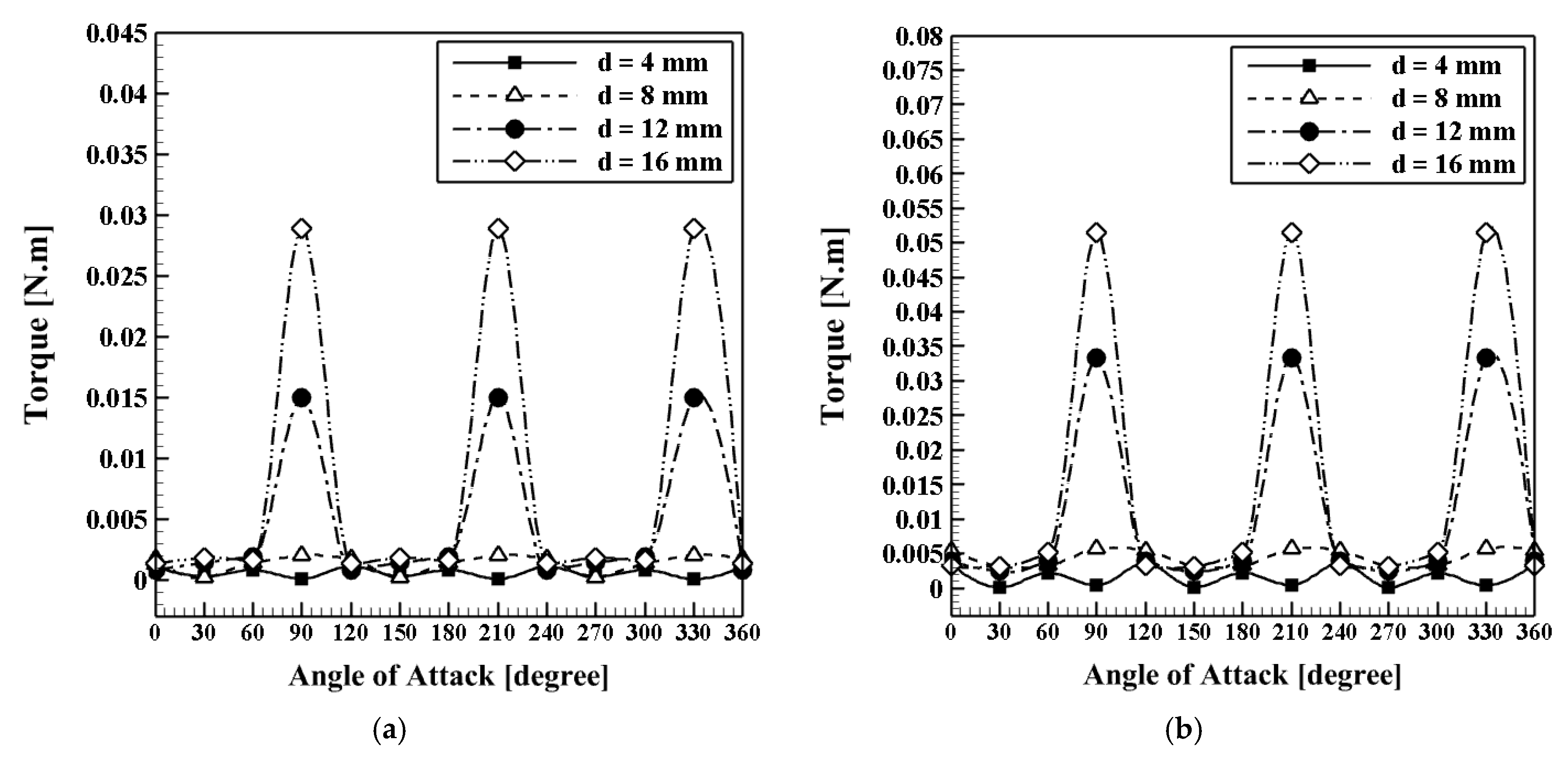
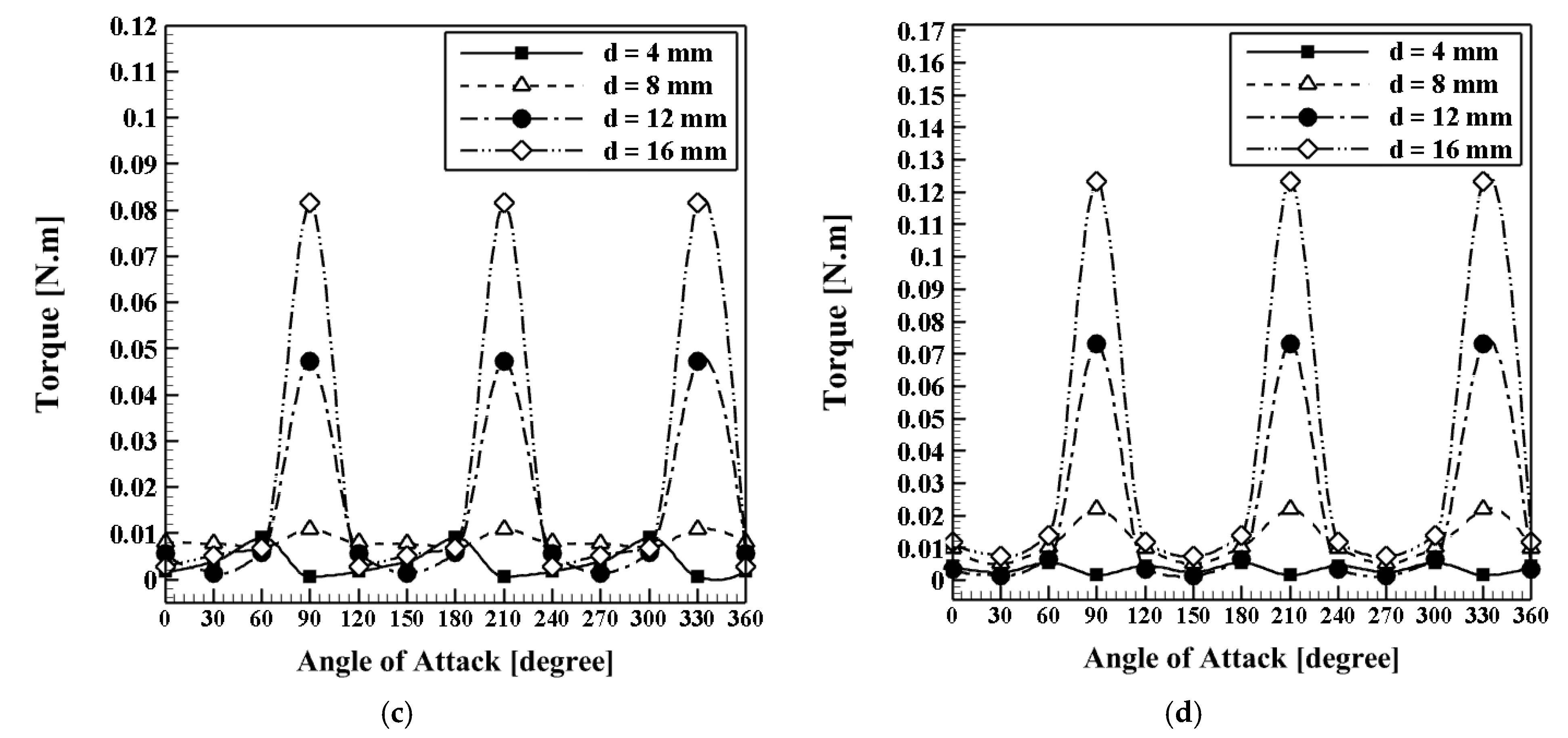
  • Due to the best position and the distance between the main and the auxiliary blade, which is equal to 6 mm, the effects of a slot on the main blade with different values of d = 4, 8, 12, and 16 mm to varying velocities of 3 to 6 m/s were investigated. The results showed that with increasing the width of the slot on the main blade from d = 4 mm to 16 mm, the output torque also increased. However, this increase has a positive effect only at a 90-degree angle.
  • The best output torque curve is related to the effect of creating a slot on the main blade with a slot width of 16 mm and at different wind velocities of 3 to 6 m/s; a simple triple-blade Savonius rotor and a triple-blade Savonius rotor with the secondary blade were compared at four angles. The results showed that by creating a slot on the main blade, the surface below the output torque diagram is not improved, and creating a slot on the main blade reduces the performance of the turbine rotor.
  • The output torque at the angle β = 130 degrees is higher than other angles. After that, the maximum torque is obtained at angles of β = 110 degrees, β = 70 degrees, and β = 50 degrees, respectively.
  • By increasing the radius of the additional blade from R = 25 mm to 43 mm, the torque is improved, and the area below the output torque curve is increased.
Although this study has provided new insight into the flow characteristics around a new proposed design for triple stack blade Savonius wind turbines, additional research is needed in order to demonstrate the viability of this design in more realistic engineering situations by the development of an experimental prototype.

Author Contributions

Conceptualization, R.N., S.S.M.A. and S.S.M.; Data curation, R.N., S.S.M.A. and S.S.M.; Formal analysis, R.N., S.S.M.A., P.N., S.S.R.K. and M.E.; Funding acquisition, M.E.; Investigation, R.N., S.S.M.A. and S.S.M.; Methodology, R.N., S.S.M.A., S.S.M., S.S.R.K. and M.E.; Project administration, S.S.M.A., P.N., S.S.R.K. and M.E.; Resources, S.S.R.K. and M.E.; Software, R.N.; Supervision, S.S.M.A.; Validation, R.N., S.S.M.A., S.S.M., P.N., S.S.R.K. and M.E.; Visualization, S.S.M., P.N., S.S.R.K. and M.E.; Writing—original draft, R.N. and S.S.M.A.; Writing—review & editing, R.N., S.S.M.A., S.S.M., P.N., S.S.R.K. and M.E. All authors have read and agreed to the published version of the manuscript.

Funding

This research was partially funded by the European Union’s Horizon 2020 Research and Innovation Programme under the Marie Sklodowska-Curie grant agreement No 834966.

Institutional Review Board Statement

Not applicable.

Informed Consent Statement

Not applicable.

Data Availability Statement

Data available on request due to restrictions eg privacy or ethical.

Acknowledgments

The authors acknowledge funding from the European Union’s Horizon 2020 Research and Innovation Programme under the Marie Sklodowska-Curie grant agreement No. 834966.

Conflicts of Interest

The authors declare no conflict of interest.

References

  1. Honarbari, A.; Najafi-Shad, S.; Saffari Pour, M.; Ajarostaghi, S.S.M.; Hassannia, A. MPPT Improvement for PMSG-Based Wind Turbines Using Extended Kalman Filter and Fuzzy Control System. Energies 2021, 14, 7503. [Google Scholar] [CrossRef]
  2. Olfian, H.; Ajarostaghi, S.S.M.; Ebrahimnataj, M.; Farhadi, M.; Arıcı, M. On the thermal performance of evacuated tube solar collector integrated with phase change material. Sustain. Energy Technol. Assess. 2022, 53, 102437. [Google Scholar] [CrossRef]
  3. Ajarostaghi, S.S.M.; Mousavi, S.S. Solar energy conversion technologies: Principles and advancements. In Solar Energy Advancements in Agriculture and Food Production Systems; Academic Press: Cambridge, MA, USA, 2022; pp. 29–76. [Google Scholar]
  4. Javadi, H.; Ajarostaghi, S.S.M.; Mousavi, S.S.; Pourfallah, M. Thermal analysis of a triple helix ground heat exchanger using numerical simulation and multiple linear regression. Geothermics 2019, 81, 53–73. [Google Scholar] [CrossRef]
  5. Mousavi Ajarostaghi, S.S.; Javadi, H.; Mousavi, S.S.; Poncet, S.; Pourfallah, M. Thermal performance of a single U-tube ground heat exchanger: A parametric study. J. Cent. South Univ. 2021, 28, 3580–3598. [Google Scholar] [CrossRef]
  6. O’Neill, S. Giant Turbines Poised to Claim Offshore Wind; Elsevier: Amsterdam, The Netherlands, 2021; pp. 894–896. [Google Scholar]
  7. Alipour, R.; Alipour, R.; Fardian, F.; Koloor, S.S.R.; Petrů, M. Performance improvement of a new proposed Savonius hydrokinetic turbine: A numerical investigation. Energy Rep. 2020, 6, 3051–3066. [Google Scholar] [CrossRef]
  8. Greig, C. Contemporary Research in Energy Science and Engineering. Engineering 2017, 3, 436–438. [Google Scholar] [CrossRef]
  9. Luhmann, T.; Wieben, E.; Treydel, R.; Stadler, M.; Kumm, T. An approach for cost-efficient grid integration of distributed renewable energy sources. Engineering 2015, 1, 447–452. [Google Scholar] [CrossRef] [Green Version]
  10. Alipour, R.; Alipour, R.; Rahimian Koloor, S.S.; Petrů, M.; Ghazanfari, S.A. On the performance of small-scale horizontal axis tidal current turbines. Part 1: One single turbine. Sustainability 2020, 12, 5985. [Google Scholar] [CrossRef]
  11. Roy, S.; Saha, U.K. Review on the numerical investigations into the design and development of Savonius wind rotors. Renew. Sustain. Energy Rev. 2013, 24, 73–83. [Google Scholar] [CrossRef]
  12. Gao, X.; Li, B.; Wang, T.; Sun, H.; Yang, H.; Li, Y.; Wang, Y.; Zhao, F. Investigation and validation of 3D wake model for horizontal-axis wind turbines based on filed measurements. Appl. Energy 2020, 260, 114272. [Google Scholar] [CrossRef]
  13. Energy, G.W. Global Wind Energy Market Report Wind Energy Industry Grows at Steady Pace, Adds over 8,000 MW in 2003. Available online: https://www.osti.gov/biblio/836859-global-wind-energy-market-report-wind-energy-industry-grows-steady-pace-adds-over-mw (accessed on 23 May 2022).
  14. Anup, K.C.; Whale, J.; Urmee, T. Urban wind conditions and small wind turbines in the built environment: A review. Renew. Energy 2019, 131, 268–283. [Google Scholar]
  15. Lipian, M.; Dobrev, I.; Massouh, F.; Jozwik, K. Small wind turbine augmentation: Numerical investigations of shrouded-and twin-rotor wind turbines. Energy 2020, 201, 117588. [Google Scholar] [CrossRef]
  16. Menegozzo, L.; Dal Monte, A.; Benini, E.; Benato, A. Small wind turbines: A numerical study for aerodynamic performance assessment under gust conditions. Renew. Energy 2018, 121, 123–132. [Google Scholar] [CrossRef]
  17. Reinauer, T.; Hansen, U.E. Determinants of adoption in open-source hardware: A review of small wind turbines. Technovation 2021, 106, 102289. [Google Scholar] [CrossRef]
  18. Eriksson, S.; Bernhoff, H.; Leijon, M. Evaluation of different turbine concepts for wind power. Renew. Sustain. Energy Rev. 2008, 12, 1419–1434. [Google Scholar] [CrossRef]
  19. Savonius, S. The S-Roter and Its Applications. Mech. Eng. 1931, 53, 333–338. [Google Scholar]
  20. Morshed, K.N.; Rahman, M.; Molina, G.; Ahmed, M. Wind tunnel testing and numerical simulation on aerodynamic performance of a three-bladed Savonius wind turbine. Int. J. Energy Environ. Eng. 2013, 4, 1–14. [Google Scholar] [CrossRef] [Green Version]
  21. Ali, M.H. Experimental comparison study for Savonius wind turbine of two three blades at low wind speed. Int. J. Mod. Eng. Res. IJMER 2013, 3, 2978–2986. [Google Scholar]
  22. Debnath, P.; Gupta, R. Flow Physics Analysis of Three-Bucket Helical Savonius Rotor at Twist Angle Using CFD. Int. J. Mod. Eng. Res. 2013, 3, 739–746. [Google Scholar]
  23. Deb, B.; Gupta, R. Fluid flow analysis of Savonius rotor at different rotor angle using CFD. ISESCO J. Sci. Technol. 2012, 8, 35–42. [Google Scholar]
  24. Yoshida, Y.; Kawamura, T. Numerical simulations of two-dimensional flows around a Savonius rotor with various curvature of the blade. Nat. Sci. Rep. Ochanomizu Univ. 2012, 63, 11–21. [Google Scholar]
  25. McTavish, S.; Feszty, D.; Sankar, T. Steady and rotating computational fluid dynamics simulations of a novel vertical axis wind turbine for small-scale power generation. Renew. Energy 2012, 41, 171–179. [Google Scholar] [CrossRef]
  26. Brown, K.A.; Brooks, R. Design and analysis of vertical axis thermoplastic composite wind turbine blade. Plast. Rubber Compos. 2010, 39, 111–121. [Google Scholar] [CrossRef]
  27. Abdi, B.; Koloor, S.S.R.; Abdullah, M.R.; Amran, A.; Yahya, M.Y. Effect of strain-rate on flexural behavior of composite sandwich panel. Appl. Mech. Mater. 2012, 229, 766–770. [Google Scholar] [CrossRef]
  28. Kashyzadeh, K.R.; Koloor, S.S.R.; Bidgoli, M.O.; Petrů, M.; Asfarjani, A.A. An optimum fatigue design of polymer composite compressed natural gas tank using hybrid finite element-response surface methods. Polymers 2021, 13, 483. [Google Scholar] [CrossRef]
  29. Armstrong, S.; Fiedler, A.; Tullis, S. Flow separation on a high Reynolds number, high solidity vertical axis wind turbine with straight and canted blades and canted blades with fences. Renew. Energy 2012, 41, 13–22. [Google Scholar] [CrossRef]
  30. Armstrong, S.; Tullis, S. Power performance of canted blades for a vertical axis wind turbine. J. Renew. Sustain. Energy 2011, 3, 013106. [Google Scholar] [CrossRef]
  31. Chan, C.M.; Bai, H.L.; He, D.Q. Blade shape optimization of the Savonius wind turbine using a genetic algorithm. Appl. Energy 2018, 213, 148–157. [Google Scholar] [CrossRef]
  32. Ferrari, G.; Federici, D.; Schito, P.; Inzoli, F.; Mereu, R. CFD study of Savonius wind turbine: 3D model validation and parametric analysis. Renew. Energy 2017, 105, 722–734. [Google Scholar] [CrossRef]
  33. Kothe, L.B.; Möller, S.V.; Petry, A.P. Numerical and experimental study of a helical Savonius wind turbine and a comparison with a two-stage Savonius turbine. Renew. Energy 2020, 148, 627–638. [Google Scholar] [CrossRef]
  34. Mauro, S.; Brusca, S.; Lanzafame, R.; Messina, M. CFD modeling of a ducted Savonius wind turbine for the evaluation of the blockage effects on rotor performance. Renew. Energy 2019, 141, 28–39. [Google Scholar] [CrossRef]
  35. Bethi, R.V.; Laws, P.; Kumar, P.; Mitra, S. Modified Savonius wind turbine for harvesting wind energy from trains moving in tunnels. Renew. Energy 2019, 135, 1056–1063. [Google Scholar] [CrossRef]
  36. Mereu, R.; Federici, D.; Ferrari, G.; Schito, P.; Inzoli, F. Parametric numerical study of Savonius wind turbine interaction in a linear array. Renew. Energy 2017, 113, 1320–1332. [Google Scholar] [CrossRef]
  37. Sahim, K.; Santoso, D.; Puspitasari, D. Investigations on the effect of radius rotor in combined Darrieus-Savonius wind turbine. Int. J. Rotating Mach. 2018, 2018, 3568542. [Google Scholar] [CrossRef] [Green Version]
  38. Roshan, A.; Sagharichi, A.; Maghrebi, M.J. Nondimensional parameters’ effects on hybrid Darrieus–Savonius wind turbine performance. J. Energy Resour. Technol. 2020, 142, 011202. [Google Scholar] [CrossRef]
  39. Storti, B.A.; Dorella, J.J.; Roman, N.D.; Peralta, I.; Albanesi, A.E. Improving the efficiency of a Savonius wind turbine by designing a set of deflector plates with a metamodel-based optimization approach. Energy 2019, 186, 115814. [Google Scholar] [CrossRef]
  40. Calautit, K.; Aquino, A.; Calautit, J.K.; Nejat, P.; Jomehzadeh, F.; Hughes, B.R. A review of numerical modelling of multi-scale wind turbines and their environment. Computation 2018, 6, 24. [Google Scholar] [CrossRef] [Green Version]
  41. Zemamou, M.; Aggour, M.; Toumi, A. Review of savonius wind turbine design and performance. Energy Procedia 2017, 141, 383–388. [Google Scholar] [CrossRef]
  42. Ansys, F. 18.1 User Guide. Knowledge Resources: Online Documentation. Available online: https://www.ansys.com/academic/learning-resources (accessed on 23 May 2022).
  43. Saedodin, S.; Zaboli, M.; Ajarostaghi, S.S.M. Hydrothermal analysis of heat transfer and thermal performance characteristics in a parabolic trough solar collector with Turbulence-Inducing elements. Sustain. Energy Technol. Assess. 2021, 46, 101266. [Google Scholar] [CrossRef]
  44. Ajarostaghi, S.S.M.; Zaboli, M.; Nourbakhsh, M. Numerical evaluation of turbulence heat transfer and fluid flow of hybrid nanofluids in a pipe with innovative vortex generator. J. Therm. Anal. Calorim. 2021, 143, 1583–1597. [Google Scholar] [CrossRef]
Figure 1. 3D schematic of investigated models of modified triple-blade Savonius wind turbines including (a) simple triple-blade Savonius wind turbine, (b) triple-blade Savonius wind turbine with the secondary blades, (c) triple-blade Savonius wind turbine with secondary blades and slots, and (d) computational domains (2D) with geometrical parameters.
Sustainability 14 09816 g001
Figure 2. The computational domain with boundary conditions.
Sustainability 14 09816 g002
Figure 3. The generated grids for various studied cases.
Sustainability 14 09816 g003
Figure 4. Results of the grid-independency analysis at VWind = 5 m/s.
Sustainability 14 09816 g004
Figure 5. Results of the validation analysis and comparison between the present numerical results and experimental results of Ali’s work [21] at VWind = 5 m/s; (a) static torque coefficient value and (b) torque value.
Sustainability 14 09816 g005
Figure 6. Simple triple-blade rotor output torque curve at various wind velocities.
Sustainability 14 09816 g006
Figure 7. The velocity contours and velocity vector of the simple triple-blade rotor at wind velocity of 5 m/s for (a) α = 0 degrees, (b) α = 30 degrees, (c) α = 60 degrees, and (d) α = 90 degrees.
Sustainability 14 09816 g007
Figure 8. The produced torque versus various angles of attack for the case with secondary blades at h = 6 mm.
Sustainability 14 09816 g008
Figure 9. Contours of velocity magnitude and pressure for two different cases and various angles of attack at V = 5 m/s and h = 6 mm.
Sustainability 14 09816 g009aSustainability 14 09816 g009b
Figure 10. Influence of the slot between the main and additional (secondary) blades (h) on the produced torque at a constant wind velocity of 5 m/s.
Sustainability 14 09816 g010
Figure 11. Contours of velocity magnitude and pressure for various models at V = 5 m/s and α = 90 degrees.
Sustainability 14 09816 g011aSustainability 14 09816 g011b
Figure 12. The produced torque versus different angles of attack for the cases with and without secondary blades at (a) VWind = 3 m/s, (b) VWind = 4 m/s, (c) VWind = 5 m/s, and (d) VWind = 6 m/s; h = 6 mm.
Sustainability 14 09816 g012
Figure 13. The produced torque versus different angle of attack for various cases at (a) V = 3 m/s, (b) V = 4 m/s, (c) V = 5 m/s, and (d) V = 6 m/s; h = 6 mm and d = 16 mm.
Sustainability 14 09816 g013
Figure 14. Contours of velocity magnitude and pressure for two different cases including with and without slots and various angles of attack at V = 5 m/s, h = 6 mm, and d = 16 mm.
Sustainability 14 09816 g014aSustainability 14 09816 g014b
Figure 15. The produced torque versus different angles of attack and wind velocities for (a) d = 4 mm, (b) d = 8 mm, (c) d = 12 mm, and (d) d = 16 mm at h = 6 mm.
Sustainability 14 09816 g015
Figure 16. Torque curve: The effect of slot’s width on the output torque of Savinus turbine equipped with secondary blades and slots on the main blades; (a) VWind = 3 m/s, (b) VWind = 4 m/s, (c) VWind = 5 m/s, and (d) VWind = 6 m/s.
Sustainability 14 09816 g016aSustainability 14 09816 g016b
Figure 17. Studied geometry of the computational domain with various profiles of the secondary blade (angular position) at h = 6 mm and d = 4 mm.
Sustainability 14 09816 g017
Figure 18. The produced torque versus different angles of attack for various secondary blade angular positions at (a) V = 3 m/s, (b) V = 4 m/s, (c) V = 5 m/s, and (d) V = 6 m/s; h = 6 mm, and d = 4 mm.
Sustainability 14 09816 g018aSustainability 14 09816 g018b
Figure 19. Contours of velocity magnitude and pressure for two different angular positions of the secondary blades and slots and various angles of attack at V = 5 m/s, h = 6 mm, and d = 4 mm.
Sustainability 14 09816 g019aSustainability 14 09816 g019b
Figure 20. Studied geometry of the computational domain with various profiles of the secondary blades at β = 90 degrees, h = 6 mm, and d = 4 mm.
Sustainability 14 09816 g020
Figure 21. The produced torque versus different angles of attack for various secondary blade radiuses (R) at (a) V = 3 m/s, (b) V = 4 m/s, (c) V = 5 m/s, and (d) V = 6 m/s; h = 6 mm and d = 4 mm.
Sustainability 14 09816 g021
Figure 22. Contours of velocity magnitude and pressure for two different secondary blade’s radiuses and various angles of attack at V = 5 m/s, h = 6 mm, and d = 4 mm.
Sustainability 14 09816 g022
Table 1. The values of geometrical parameters of the present investigated models.
ParametersValue
Length of the computational domainL1700 mm
Width of the computational domainW1000 mm
Inlet velocity of the windV3-4-5-6 m/s
The rotation angle of bladesα0-30-60-90 degrees
Angular velocity ω 16-32-44-52 rad/s
Diameter of rotating area D o 210 mm
The outer diameter of the main bladesD100 mm
The outer radius of the main bladesR50 mm
The outer radius of secondary bladesr25 mm
Thickness of bladest1 mm
Distance between the two bladesh6-12-18-24 mm
Width of the slotd4-8-12-16 mm
Table 2. The torque values and static torque coefficient values of the experimental work [21] and the present study.
Angle of Attack (α)Cts
Experimental
[21]
Cts
Numerical
Error
[%]
Ts
Experimental
[21]
Ts
Numerical
Error
[%]
0 degree0.180.18050.20.01080.0107−0.9
30 degrees0.480.48270.50.02850.02860.3
60 degrees0.550.5451−0.80.03260.0323−0.9
90 degrees0.220.2161−1.70.0130.0128−1.5
Publisher’s Note: MDPI stays neutral with regard to jurisdictional claims in published maps and institutional affiliations.

