Article

The Feasibility Study, Exergy, and Exergoeconomic Analyses of a Novel Flare Gas Recovery System

1
Department of Chemical Engineering, Amirkabir University of Technology (Tehran Polytechnic), Tehran P.O. Box 15875-4413, Iran
2
Department of Chemical Engineering, School of Chemical, Petroleum and Gas Engineering, Shiraz University, Shiraz P.O. Box 71946-84334, Iran
3
Department of Energy System Engineering, Petroleum University of Technology, Abadan P.O. Box 63187-14317, Iran
4
Department of Chemical Engineering, Faculty of Petroleum, Gas and Petrochemical Engineering, Persian Gulf University, Bushehr P.O. Box 75169-13798, Iran
5
Department of Engineering, University of Exeter, Exeter EX4 4QF, UK
*
Authors to whom correspondence should be addressed.
Sustainability 2022, 14(15), 9612; https://doi.org/10.3390/su14159612
Submission received: 19 May 2022 / Revised: 14 July 2022 / Accepted: 2 August 2022 / Published: 4 August 2022

Abstract

:
One of the challenging issues that has always attracted the attention of the experts is how to control and reduce greenhouse gas emissions because of their overwhelming negative environmental impacts. Although burning the hazardous gaseous products in the flare systems boosts the safety of gas and oil fields and diminishes the internal pressure of the extraction systems, it has a catastrophic impact on the surrounding environment. In this study, a new system was designed to recover flare gas. In this system, ejectors and compressors are used in parallel to compress flare gas. One of the aims of this system is to minimize environmental disadvantages and prevent the waste of national capital. The described system is firstly simulated using the HYSYS software based on Peng–Robinson state equations. The efficiency and exergy destruction can be calculated through exergy analysis, which is the second step in the process. Finally, by considering investment and fuel cost to each exergy flow, exergoeconomic analysis was evaluated. From the exergy analysis results, it can be concluded that the ejectors have the highest exergy efficiency (99.87%) compared with other devices in the process, and their total exergy destruction rate is 8458.35 kW. Findings from exergoeconomic analysis suggest that the highest exergy destruction cost for flare system is associated with EJ-3 ejector which is 89.01 USD/h. Furthermore, a sensitivity analysis was applied to specify the dependency of the exergy and exergoeconomic results of this process on the flow rate of recovered gas and flare gas pressure as important input plant feed parameters. By this study, we aim to evaluate the feasibility of the implementation of this system in an industrial plant.

1. Introduction

Scientists believe reducing greenhouse and pollutant gas emissions at industrial companies is one of the most important problems of the 21st century due to their negative impact on the environment [1]. A major source of greenhouse gases and other pollutants in the atmosphere is the burning of co-products of gas- and petroleum-based products. The use of flares to burn these dangerous gaseous products improves safety at the plants, but it has a negative impact on the environment [2]. Alongside heat and noise emissions which are normal consequences of flaring, it causes other problems which can be concluded as follows: (1) By burning low-quality gas in flares, many impurities and toxic particles and gases (such as CO and NOx) are released into the atmosphere, which can be very harmful to human health, especially at high concentration. (2) The waste gases resulting from flares contain chemical substances such as SOx, CO2, and H2S featured as weak acids which are corrosive in the presence of rainfall and result in acidic rain. Acidic rain inflicts damage to crops and buildings and can also cause problems for the ecosystem. (3) CO2, which is one of the main products of gas burning in flares, is a major greenhouse gas, and its accumulation in the atmosphere is the main reason for the global warming phenomenon in recent years [3].
Flare gas recovery units have many advantages, both from an economic and environmental standpoint such as enhancing production efficiency, reducing maintenance and operating costs, and decreasing noise and flare emissions. Recently, the environmental and economic regulations and policies have made the industrial parties implement Flare Gas Recovery Systems (FGRS) due to the fact that it provokes the reduction in burnt gas in flares [4]. Nevertheless, after more than a decade of the implementation of FGRSs in developed nations, these systems are considered as a new method of waste management in industrial plants. By applying this new technology, the gases which are burnt in flares can be recovered to be used in other units of the plants. The compression section is the most important of the various parts of a flare gas recovery system. This compression section normally includes either a compressor or an ejector.
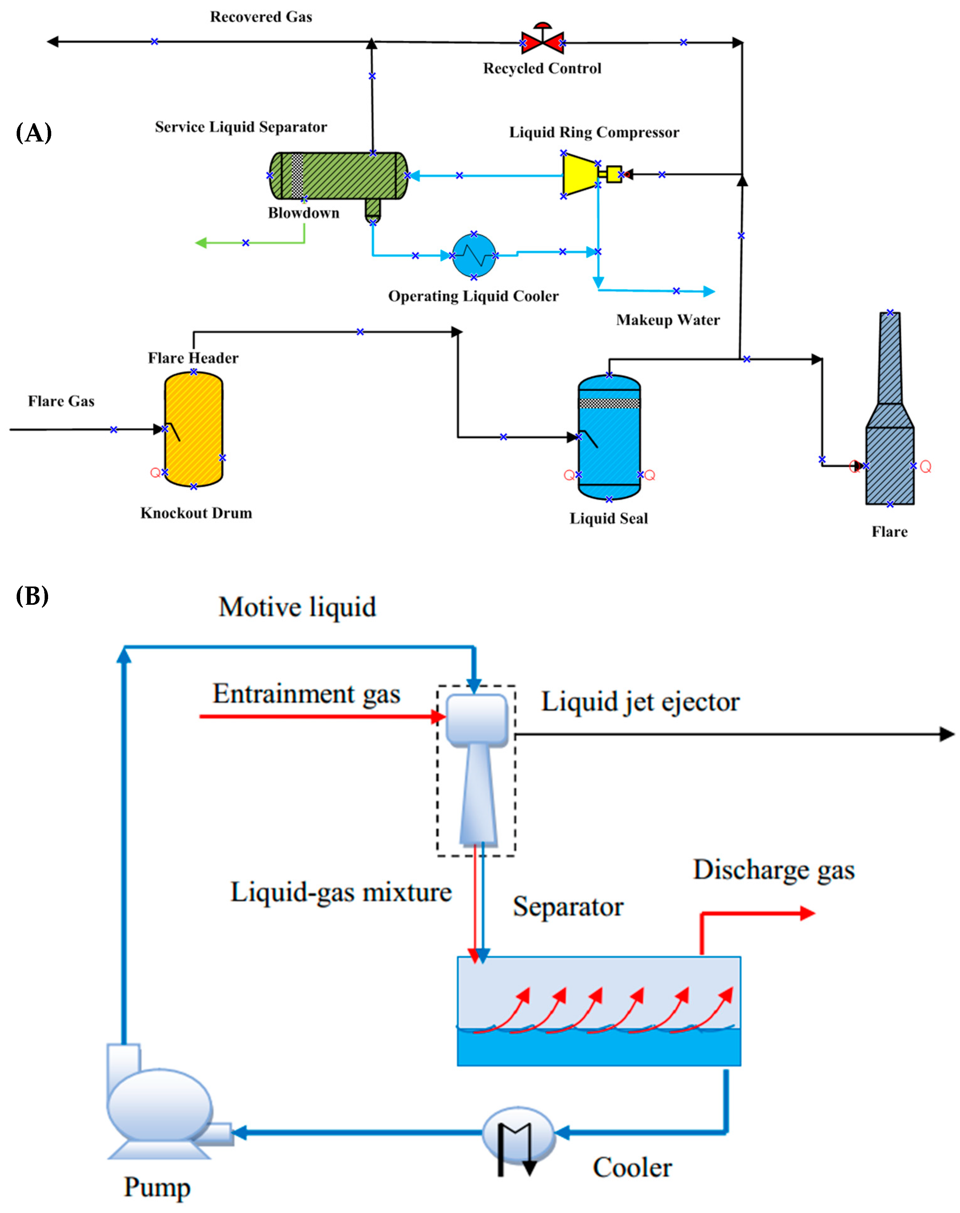
The design of a compressor for the compression section of an FGRS is influenced by several elements listed as archetypal such as initial cost and size and function such as process requirements, efficiency, operating, and maintenance requirements. In recent years many different types of compressors such as Dry Screw Compressors (DSCs), Sliding Vane Compressors (SVCs), Reciprocating Compressors (RCs), Liquid Ring Compressors (LRCs), and oil-injected compressors have been used in FGRSs. Generally, LRC or RC are the favorite types of compressors for use in an FGRS. An advantage that this type has over other kinds of compressors is that in the LRCs, the gas is cooled down during compression by losing its heat to a cooling fluid (usually water) inside the compressor [5]. Figure 1A depicts a schematic of an FGRS with LRC. After collecting flare gas from the flare header into a knock-out drum, it is then directed towards the compressor. Afterward, the gas is compressed and discharged into a dual-phase separator in which more liquid is separated from it. The liquid is then pumped through a heat exchanger and is sent back to the compressor as the inlet service liquid. The compressed gas also exits in the separator drum to be sent to the plant fuel gas header or other parts of the plant [5]. However, this system also has some disadvantages for example, compressors are expensive, and they have many rotating parts, which mean their maintenance and repair costs are high. They also produce a great deal of noise [6].
Another design currently being used in the industry for flare gas recovery is to employ ejectors instead of compressors in the compression section. An ejector unit is a long-lasting device for pumping dirty or harmful gases due to its simplicity and lack of moving parts [7]. A schematic design of an FGRS with an ejector is shown in Figure 1B. In these systems, ejectors are used to increase the pressure of flare gases to up to 150 times at which they can be recovered. Ejectors are considered as equipment with high reliability and at the same time simple in order to compress fluids. The operation of this device is based on Bernoulli’s principle, which implies reduction in pressure when the speed of the motive fluid increases in the nozzle. This low-pressure section draws the entrained gas towards it. Although flare gas recovery systems using ejectors have simple designs, they have some issues too; for instance, they have a high degree of susceptibility to change in operating conditions and in order to compress a small amount of secondary fluid, a large amount of motive fluid is required.
Many studies have been performed so far to evaluate flare gas recovery from technical, environmental, and economic standpoints. Mousavi et al. investigated three main FGR methods to optimize the level of energy consumption and prevent pollution by exploiting the abilities of environmental flow diagrams as well as a package of simulation software. They found that when gas flare recovery methods are used, the amount of CO2, CO, and NOX in the furnaces, dehumidifier, and flare reduces by 100%, 100%, and about 57%, respectively [8]. Studies by Ojijiagwo et al. found that gas to wire (GTW) technology can be economically viable as part of gas flare management. The investigation conducted a cost-benefit analysis of the GTW technology and its potential impact [9]. An experimental study was conducted to determine the flare gas’s composition and flow rate by Comodi et al. [6]. It was estimated how much energy can be recovered each year and an economic evaluation was performed. Khalili-Garakani et al. reviewed different flare gas recovery technologies to assess the potential of their implementation in the gas and petroleum industries in Iran. According to their findings, flare gas recovery systems can both reduce emissions and generate a significant profit [10]. Asadi et el. investigated and optimized the performance of a novel flare gas recovery process in which compression and treatment of flare gas are carried out simultaneously [11]. Exergy analysis attributes as a sound thermodynamic analysis technique which is evolved from the Second Law of Thermodynamics and also provides a rational and meaningful setting to evaluate and scrutinize processes and systems [12]. Exergy analysis has been widely used in various processes such as sweet gas production [13,14,15], Liquefied Natural Gas (LNG), and Natural Gas Liquids (NGL) production processes [16,17], Gas to Liquid (GTL) [18], and power generation [19,20,21].
This study proposes a new system for flare gas recovery in which energy consumption is at an optimum level. The novelty of this work lies in the utilization of both compressors and ejectors being used at the same time and parallel to each other for the purpose of gas compression. From the Abadan Oil Refining Company, we took the flare gas process data. The Aspen Hysys software was employed to simulate this novel system. After completing the simulation, an exergy analysis was applied to investigate the performance of all the equipment of the process from the perspective of energy conversion quality and deviation from the ideal condition. Exergy and exergoeconomic analyses were used to identify possible ways to optimize the system technically and economically. The parallel ejector-compressor system arrangement can increase the performance and profitability of the flare gas recovery system. From a technical point of view, refinery inlet natural gas has a limited, constant volume flow rate. Therefore, it is desirable to consume less natural gas. In this parallel ejector-compressor system (compared with ejector FGRS), the amount of flare gas, as the secondary fluid, that enters the ejector reduces significantly and as a result less natural gas, as the motive fluid, is required. Moreover, compared with compressor FGRS, the flare gas flow rate that enters the compressors in this parallel system remarkably decreases and therefore smaller (and less expensive) compressors with less noise are needed. This can help the system to save more energy efficiency and have more flexibility.

2. Process Description

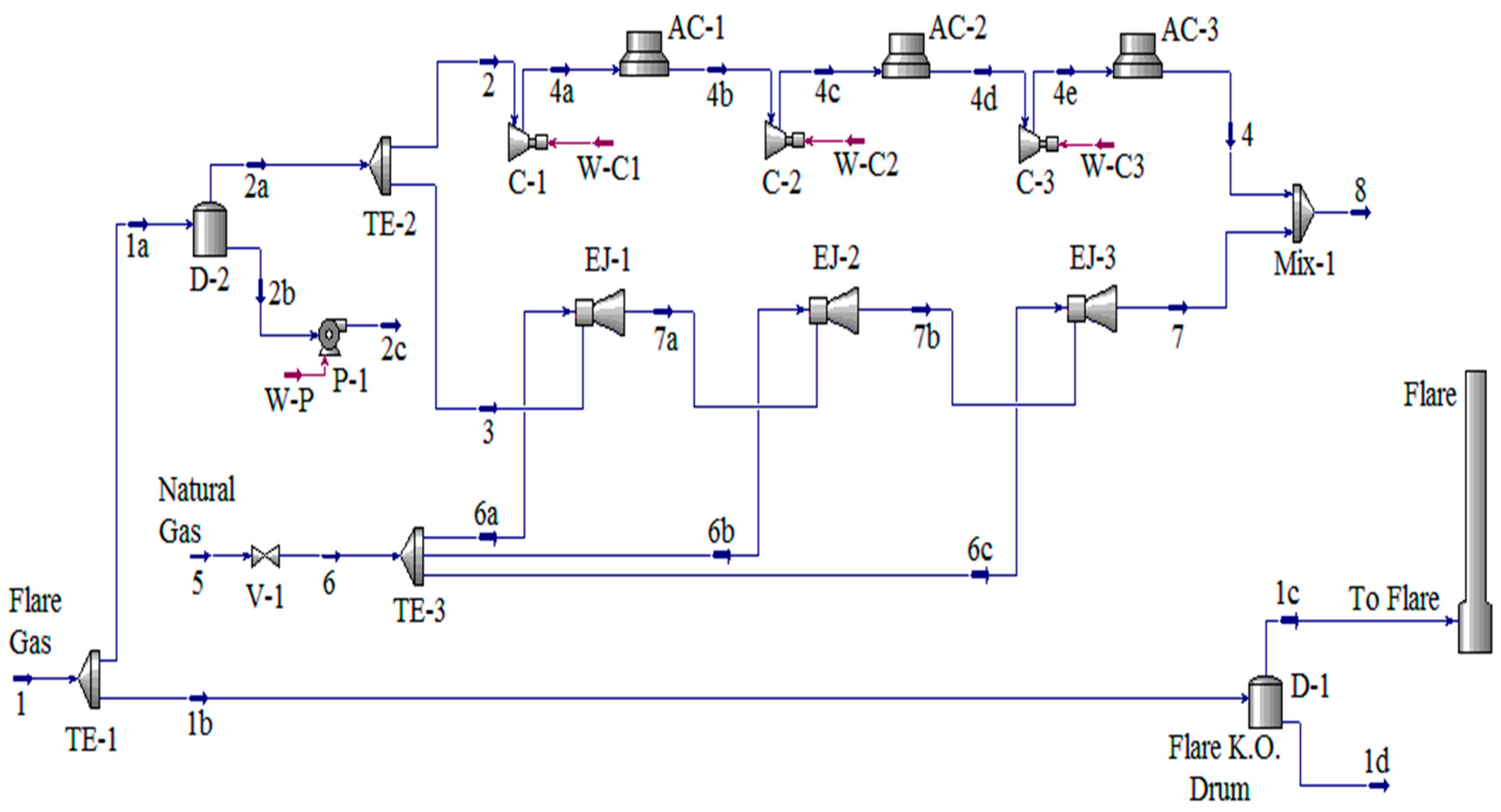
The main equipment of the designed flare gas recovery system (FGRS) in this study includes compressors, ejectors, air coolers, and separators. The flare gas process data (flow rate, gas composition, and gas condition) was taken from the Abadan refinery. The process flow diagram of the designed FGRS is demonstrated in Figure 2. In this Figure, stream number 1, the flare gas is divided into streams 1a and 1b by the TE-1 header. Flow 1b burns in the flare after passing through the drum and separation of its liquid depending on the operating conditions. The stream that enters the designed recovery system is current 1a and its flow rate stream is about 5000 kg/h. Liquids in stream 1a are separated by the D-2 flash tank, then stream 2a is sent to the compression system, which consists of multiple compressors and ejectors. After each compressor, an air cooler, AC, is installed which reduces the temperature of the compressed gas.
The only energy consuming devices in this system are compressors and air coolers. The first, second, and third compressors consume 297, 97, and 55 kW electrical energy, respectively. Moreover, the first, the second, and the third air coolers consume 32, 26, and 21 kW, respectively. The ejectors’ motive gas is natural gas injected into all three ejectors to create a vacuum region and entrain secondary gas streams. The first, the second, and the third air ejectors use 66,000, 132,000, and about 265,000 kg/h of natural gas, respectively. Air coolers are designed to reduce the compressors’ outlet temperatures to 40 °C. This decrease in temperature causes the flare gas to be compressed to the desired pressure in three stages. The temperature and pressure of stream 8 are 40 °C and 60 bar, respectively, which is suitable for use in gas turbine systems for power generation. Properties of all streams in this system including temperatures, pressures, entropies, enthalpies, and flow rates are presented in Table 1. Simplicity and low energy requirement are important characteristics of this process.

3. Numerical Implementation

The thermodynamic analyses are founded on implementing a process model and executing simulation using common software packages. In this study, the simulation of the designed FGRS is performed by Aspen HYSYS [22]. Every process simulation begins with selecting a suitable equation of state to simulate the process. A successful simulation relies heavily on choosing the right equation of state. The state equation of Peng–Robinson (PR) is frequently recommended for simulating systems containing oil and gas [23,24,25,26]. In this research, the Peng–Robinson (PR) equation was used for the simulation of FGRS. The Peng–Robinson (PR) equation was used for petrochemical, petroleum, and gas applications within a wide range of temperature and pressure values. It adequately describes both single phase and multi-phase systems. In addition, several cases and applications of flare gas recovery system similar to our case and within the range of applications of PR equation (T and P) were performed using the quoted equation, which leads us to say that the PR equation is the most appropriate one for our case. The main equations are provided below [27]:
P = RT v b a v v + b + b v b
where v is molar volume. The Peng–Robinson constants are determined from the critical properties p c , T c as [27]:
a = 0 . 457235   R 2   T c 2 p c
b = 0 . 077796   R   T c p c

3.1. Exergy Analysis

The first and second laws of thermodynamics are recognized as robust toolkits in energy consumption processes that enable the exergy analysis in qualitative and quantitative considerations and assessments. Exergy analysis is a technique in thermodynamic analysis to determine the maximum useful work that can be accomplished with a given amount of input energy. In fact, exergy analysis discusses the most efficient and usable part to manage the effective part in the system’s performance. The efficiencies expressed around exergy analysis are very effective criteria for system improvement. In the current work, exergy analysis aims to ascertain the FGR system elements’ efficiency and compare it with each equipment’s ideal state. Streams with much higher exergy are much more expensive than energies with less exergy. Table 2 presents the process’s descriptions of ejectors, air coolers, and compressors.
The state of the system and its environment are a constructive component of exergy. The system at the temperature of T0 and pressure P0 must exchange heat with the environment. This means that when a system has no difference in temperature, pressure, etc., with its surroundings, it does not have the power to go through the process. Accordingly, the dead state is defined as a system in balance with its surrounding environment, where the system is in balance in density, heat, and mechanics with its surroundings.

3.1.1. Exergy Efficiency

For each element, the ratio of ideal product exergy to consumed fuel exergy is the definition of the exergy efficiency. In each element, the product and fuel are chosen based on the desired outcome as well as the resources required to achieve that outcome. The major important parameters in exergy analysis are exergy efficiency and exergy destruction rate and ratio. The following is the equation for the exergy balance of a control volume under steady-state conditions [12]:
E F , K =   E ˙ P , k +   E ˙ D , k  
where EF,K is exergy rates of fuel and EP,K and ED,K are the exergy rates of product and destruction, respectively. As previously stated, an element’s exergy efficiency is defined as the product-to-fuel ratio. This means that both exergy efficiency and exergy destruction can be calculated simultaneously.
ɛ =   E ˙ P , k   E ˙ F , k

3.1.2. Physical Exergy

Physical exergy is equivalent to the theoretical work that the system reaches from the initial point (T and P) to the second point with the ambient state (T0 and P0) [12]:
e ph = h h o T o s s o

3.1.3. Chemical Exergy

When the flow of material from the ambient state reaches the dead state (T0 and P0), by a reversible process that includes only heat and mass transfer, and contraction and expansion, the amount of work obtained is equal to chemical exergy. According to what has been said, in order to obtain chemical exergy, in addition to the physical condition of the material stream (temperature and pressure), its chemical composition should also be determined. Chemical exergy for a flow is obtained from the following equation [12]:
e ch = x i e i o + G x i G i

3.1.4. Irreversibility

Irreversibility is defined as the difference between reversible work and useful work. When the process is reversible, irreversibility is zero. Irreversibility indicates the amount of energy that can be transformed into work, but this has not happened. Irreversibility shows the degree of inefficiency of a system. To improve the performance of a complex system, the irreversibility associated with each device should be determined and then reduced [12].
I = W rev W u

3.1.5. Exergy Balance

The exergy balance equation for a control volume is as follows [12]:
E q W cv + E i E o I = 0
In this equation, the difference between input and output exergy indicates the degree of irreversibility in the control volume. To evaluate the efficiency and to optimize the designed system, exergy efficiency and an optimal process to determine the cost of different equipment in the system are required. Table A1 shows the equations for exergy efficiency and irreversibility for each device. Moreover, the thermodynamic and calculated exergy of process streams are presented in Table 3.
4. Exergoeconomic Analysis

Exergoeconomic is a method in system assessment in which exergy and economic analyses are performed at the same time to produce the required information for a system design. In this analysis, by using the economic and thermodynamic principles and providing an economical price to the exergy flow, a balance occurs between the investment costs and the exergy flow costs, which provides valuable information for analyzing and optimizing the performance of these systems. This analysis is essential for such an expensive system to form the reliability of the performance and the cost-effectiveness of the system. Developing an economic model is the first step in exergoeconomic analysis.

4.1. Economic Model Assumption

Some assumptions were made in order to perform an exergoeconomic analysis and optimize this system. Cost balance equations are considered in stable conditions, also annual fuel, repair, and maintenance costs of the systems must be taken into account. An economic evaluation of the system is according to the TRR economic model. In this model, the cost of equipment and fuels and the total required investment are estimated annually. These cost elements may change significantly during the economic life cycle of the plant. This system should therefore be evaluated using annual levelized costs for all its components. Approximations of total investment costs and assumptions about input economic and operational factors as well as business considerations are used to calculate total revenue. The final step is to levelize non-uniform annual costs associated with the calculated investment, operation, maintenance, and fuel costs.

4.2. Calculation of Revenue Requirements

Total required revenue for a system can be defined as the amount of revenue that must be generated by the system every year in order to compensate all system costs for the first year and make the system viable for the next operation economically. Carrying Charges (CCs) and expenses are the major parts of system costs; generally, carrying charges allocating for costs dependent investment. Total capital recovery, taxes, and insurance are some examples of these investment costs. Moreover, expenses refer to the payments associated with system operation that are composed of Fuel Costs (FCs) and economic constants for explained parameters are provided in Table A2.

4.3. Costs Levelizing

In this research, simple economic modeling was used to obtain the equipment’s total investment costs and Operation and Maintenance Costs (OMCs). The following equation shows this simple modeling mathematically. It should be noted that a complete method of this modeling is provided in the reference [28]. The equipment price is estimated by equations formerly invented, which are also widely used in estimating prices. Series for carrying charges (CCj) and expenses such as OMCj and fuel costs (FCj) for the jth year of operation are not uniform series. Generally, Fuel Costs (FCs) rise with system operation years, while investment costs decrease with system operation years [28,29]. Levelized costs for Total Revenue Requirement (TRRL) can be determined by [28,29]:
TRR L = CRF 1 BL TRR j 1 + i eff j  
where TRRj, BL, CRF, and ieff denote the revenue requirement in the jth year of operation, the economic life cycle of the system (in years), capital recovery factor, and the average yearly rate of effective system devaluation, respectively. Here, the assumption is that all financial transfers take place at the end of each year. The capital recovery factor can be determined by the following expression [28,29]:
  CRF = i eff 1 + i eff BL 1 + i eff BL 1  
In this case study, TRRj represents the total of four different yearly costs: Total Capital Recovery (TCR), the minimum Return on Investment (ROI), Fuel Costs (FCs), and Operation and Maintenance Costs (OMCs) [30].
TRR j =   TCR j + ROI j + FC j + OMC j  
Fuel cost for the proposed system includes electricity and natural gas, which is determined for the first year of the operation by the following expression:
FC O =   C w × W ˙ × τ
For electricity fuel t is the operating hours of the system (7300 h in a year) and W denotes the compressor power in kilowatts, and Cw represents a constant associated with the electricity cost that is assumed to be 0.071 (USD/kW h). The following equation is used to calculate electricity cost in the jth year:
FC j =   FC 0 1 + r FC j  
For the series, FCL’s levelized value is the product of the first year’s fuel cost and the constant-escalation levelization factor (CELF):
FC L =   FC 0 × CELF = FC 0 K FC 1 K FC BL 1 K FC   CRF  
K FC = 1   +   r FC 1   +   i iff r FC =   constant
The annual fuel cost escalation rate and capital recovery factor are denoted by the terms rFC and CRF. The following is the formula for calculating the annual levelized operation and maintenance cost (OMCL) [16,31]:
OMC L =   OMC 0 × CELF = OMC 0 K OMC 1 K OMC BL 1 K OMC CRF
K OMC = 1 + r OMC 1 + i iff r OMC = constant
CC L = TRR L FC L OMC L  
The main difference between an economic analysis that is part of an exergoeconomic analysis and a conventional economic analysis is that the former is conducted at the component level. Annual capital investment, with superscript CI (capital investment) and annual operation and maintenance costs with superscript OMC for the whole system, can be divided based on the ratio of the kth element cost in the system to the total purchasing cost of system equipment (PECtot = K PEC ) [16,29]. The first step for this analysis is to estimate the purchasing cost of devices in the process by using purchasing equations in Table 4.
Z ˙ K CI = CC L τ   PEC k k PEC k
Z ˙ k OM = OMC L τ   PEC k k PEC k
where PECk denotes the cost of purchase of the kth element and s represents the system operating time (working hours) in a 1-year period at full capacity. The term Zk shows the rate of costs related to capital investment as well as operating and maintenance costs for the kth element. Using the preceding equations:
Z ˙ k = Z ˙ k CI + Z ˙ k OM = CC L + OMC L τ   PEC k k PEC k
Equation (23) can be used to determine the levelized cost rate associated with the costs supplied for the entire system:
C ˙ f = FC L τ
Levelized costs such as ZCI and ZOM and CF are often utilized as input parameters for the exergoeconomic analysis. As shown in Table A3, the cost results are the total purchase, repair, and maintenance costs of each device for FGRS.

4.4. Cost Balance Equations

Thermodynamic functional inefficiencies are indicated by parameters called exergy destruction. Many analyses were performed to investigate the reason for the inefficiency of technical systems. Therefore, the inefficiencies of system equipment must be specified. Understanding inefficiency costs is very important for improving the economic performance and reducing the final production costs. In the process of costing exergy flows, the cost is allocated to each flow. The cost associated with the flow j (Ċj) is multiplied by the flow exergy rate (Ėj) on the cost per exergy unit (cj):
C ˙ j = c j E ˙ j = c j e j m ˙ j
Exergy transfers associated with heat and work also have a cost. Where USD/GJ is the average cost per exergy unit for cj, cq, and cw.
C ˙ w = c w W ˙
Q ˙ q = c q Q ˙
According to the previous assumption, the intensity of the cost of outlet flow of each processing device is equivalent to the total intensity of inlet costs, which includes the cost of imported exergy flows along with the purchase cost of equipment and fuel cost. The flows exergy costing process involves cost balance equations that are formulated separately for each process equipment. A cost balance used for the K device shows that the total cost of outflows is equal to the total cost of inlet flows and investment and maintenance costs.
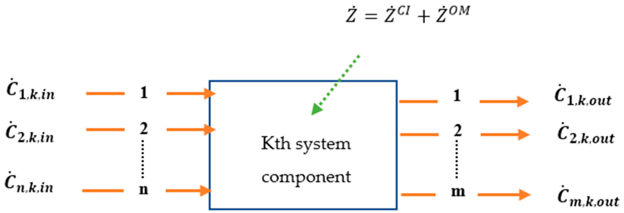
According to Figure 3, the cost balance equations of the exergy-dependent economic model for each processing device are as follows [29,33]:
j = 1 n C ˙ j , k in + Z ˙ k CI + Z ˙ k OMC = j = 1 m C ˙ j , k out
j = 1 n ( c . E ˙ ) j , k in + Z ˙ k CI + Z ˙ k OMC = j = 1 m ( c . E ˙ ) j , k out
When the cost balance equation is applied to a system, there is actually more than one output stream. In this model, the number of parameters related to unspecified expenses is greater than the number of cost balance equations. Therefore, thermodynamic auxiliary equations can be used to solve the equation. Hence linear equations can be created for each element by using cost balance and auxiliary equations gained as follows [29,33]:
[ E ˙ K ] × [ C K ] = [ Z ˙ K ]  
where [ E ˙ K ] is the exergy intensity matrix, [ C K ] denotes the unknown exergy cost vector, and [ Z ˙ K ] represents the factor vector. The cost rate of each stream can be determined by solving these equations. The main equations and auxiliary equations for FGRS are shown in Table 5 and Table 6.
In order to obtain the costs of each exergy current in accordance with the cost balancing formulas as described before, parameters are calculated based on exergoeconomic evaluation. The intensity cost of each flow is also obtained by dividing the cost of each flow by its exergy. Both the flow cost parameters and the cost intensity of each flow (unit exergy cost of FGRS streams) are shown in Table 7.

4.5. Exergoeconomic Variables

A system’s exergoeconomic variables are determined using the exergy unit cost and cost rate associated with each mass and exergy stream. Systems with the highest production costs return at the lowest fuel and investment and are the most acceptable system. For most well-designed devices, irreversible costs are reduced while investment and repair and maintenance costs increase. In this analysis, parameters related to the process equipment and the intensity of costs related to each mass stream are used for cost estimation. The cost of exergy losses for the entire system is obtained by multiplying the average fuel exergy costs by the irreversibility rate of the entire system. As stated in exergy calculations, product and fuel definitions of each process equipment are used to estimate exergy efficiency to form parameters, which are called fuel and product cost. The average fuel cost for each piece of equipment is calculated using the following equation [16]:
c F , k = C ˙ F , k E ˙ F , k
The value of the CF,k is related to the location of the equipment in the whole system and the interactions between that device and other process equipment. The average product unit cost for each piece of equipment is evaluated by [16]:
c P , k = C ˙ P , k E ˙ P , k
The determination of each element’s exergy destruction cost is an essential part of the exergoeconomic analysis of an exergy system. The exergy destruction cost rate associated with the kth element in a system is regarded as an unspecified cost that can only be known by conducting an exergoeconomic analysis. If the price of producing a product remains relatively stable, the additional fuel costs needed to compensate for exergy destruction can be calculated [16].
C ˙ D , k = c F , k E ˙ D , k
The relative cost difference (rk) is calculated using the following equation [16]:
r k = c P , k c F , k c F , k
Also, the exergoeconomic factor equation, which represents the ratio of investment costs to the total costs related to exergy loss and investment costs, is provided below [16]:
f k = Z ˙ k Z ˙ k + C ˙ D

5. Results and Discussion

5.1. Exergy Analysis Results

In the current study, an exergy analysis was conducted on a flare gas recovery system. Exergy destruction rate and ratio, as well as exergy efficiency, are three key parameters shown in the exergy analysis. Considering a control volume at steady-state condition, the analysis results are presented in Table 8. The most important conclusion to be drawn from the table of exergy indices is to understand which device is in the worst condition in terms of thermodynamic performance. This diagnosis is possible using the Exergy Destruction Index (or Irreversibility). According to Table 8, among all equipment, ejector EJ-3 has the greatest irreversibility and exergy efficiency (8458.35 kW and 99.87%). Compared with other equipment, ejectors have the highest pressure loss. It causes the physical exergy destruction to increase. As a result, the exergy destruction and irreversibility of ejectors are greater than other devices. The next highest irreversibility values are related to units EJ-2 and EJ-1. However, that is not the end of the matter, and the exergy efficiency must be considered to assess system elements individually and compare the performance of each element among all. For example, the ejectors have the highest exergy efficiency and exergy destruction rate in this system. This means that both of these parameters must be considered in the analysis.

5.2. Exergoeconomic Analysis Results

An exergy analysis is sufficient for thermodynamic analysis of the system. However, an exergoeconomic analysis allows us to establish a logical link between initial investment and current failure costs, which enables us to determine the system’s economic viability. In this analysis, the first step is to estimate the investment costs, as presented in Table A3. In the next step, each stream’s energy unit cost is calculated using the total revenue requirement technique and the cost balance equation (Table 7). Finally, by finding the exergoeconomic factor and relative cost difference (Table 9), the analysis demonstrates that the exergoeconomic factor simultaneously describes the system’s exergy efficiency and investment costs. A high exergoeconomic factor value indicates that lowering the element’s costs is necessary in order to reduce system costs, whereas a small exergoeconomic factor represents that, to lower the system cost, a system’s effectiveness and efficiency must be improved.
According to Table 9, ejectors have the worst performance because they have the highest destruction cost (89.01 USD/h) and air coolers have the lowest exergy destruction cost (0.85 USD/h). Another important indicator of exergoeconomic analysis is the exergoeconomic factor (f). The value of exergoeconomic factor of compressors and air coolers is very high compared with others, so in order to improve the economy of this system, the purchasing cost of these two pieces of equipment should be reduced. In addition, the numerical value of exergoeconomic factor for the ejectors is in the lowest state (2.28%), so to improve the system’s economy, the thermodynamic performance of this equipment must be improved.
(r) is a measure of the degree to which the exergy cost of a product exceeds the exergy cost of the fuel, and it is an important factor in evaluating and optimizing the system’s performance. In this FGRS, the maximum and the minimum relative cost differences are those of C-2 compressor (338.34) and EJ-1 ejector (0.007), respectively. The exergy rate cost in an element depends on the magnitudes of fuel and product exergy costs. The highest fuel cost rate is that of ejectors and air coolers which is 19.72 USD/Gj, while the highest rate of product cost is associated with C-3 compressor (103.05 USD/Gj). The high value of fuel cost rate in the ejectors shows that their exergy destruction cost is far greater than other equipment.

5.3. Sensitivity Analysis

A sensitivity analysis is a technique in which the inputs of a system are changed in an organized way to see the effects of these changes on the output which can show the right way for system optimization [34]. In this research, system inputs are the flow rate of recovered gas and flare gas pressure and the outputs include exergoeconomic factors, relative cost difference, destruction cost, exergy efficiency, and exergy destruction.
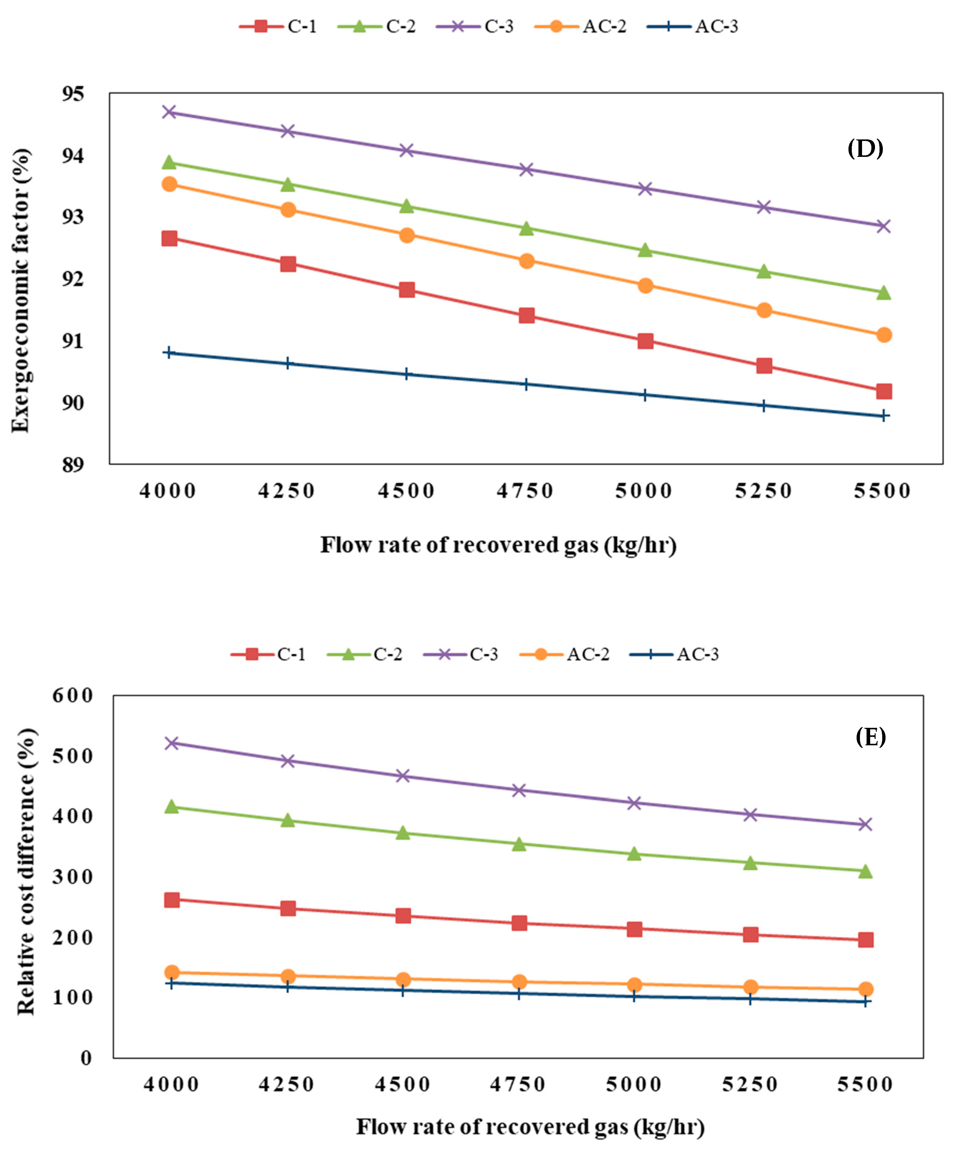
The results of sensitivity analyses of the mentioned output parameters versus the flow rate of recovered gas are illustrated in Figure 4A–E. According to Figure 4A, the compressor C-1 is a highly sensitive element in comparison with other equipment. As it turns out, the exergy destruction of this device enhances with increasing gas flow rate. As the inlet gas flow rate to the compressor increases, the outlet gas pressure boosts and more work is performed, thus increasing the exergy degradation. According to Figure 4B, the exergy efficiencies of the compressors are not sensitive to gas flow rate, but it can be seen that the air cooler efficiency boosts slightly with raising the gas flow rate because when the gas flow rate increases, heat transfer also rises and consequently the efficiency of the air cooler enhances. Figure 4C shows that as the gas flow rate increases, the exergy destruction cost of compressors rises. One reason for this increment is the irreversibility of the compressor’s pace with enhancing gas flow rate. According to Figure 4D, the exergoeconomic factor of air coolers and compressors reduce as the gas flow increases. A reason for this is the increase in the irreversible cost of this equipment versus the increase in the gas flow rate. According to Figure 4E, with raising the gas flow rate, the relative cost difference of air coolers and compressors decreases.
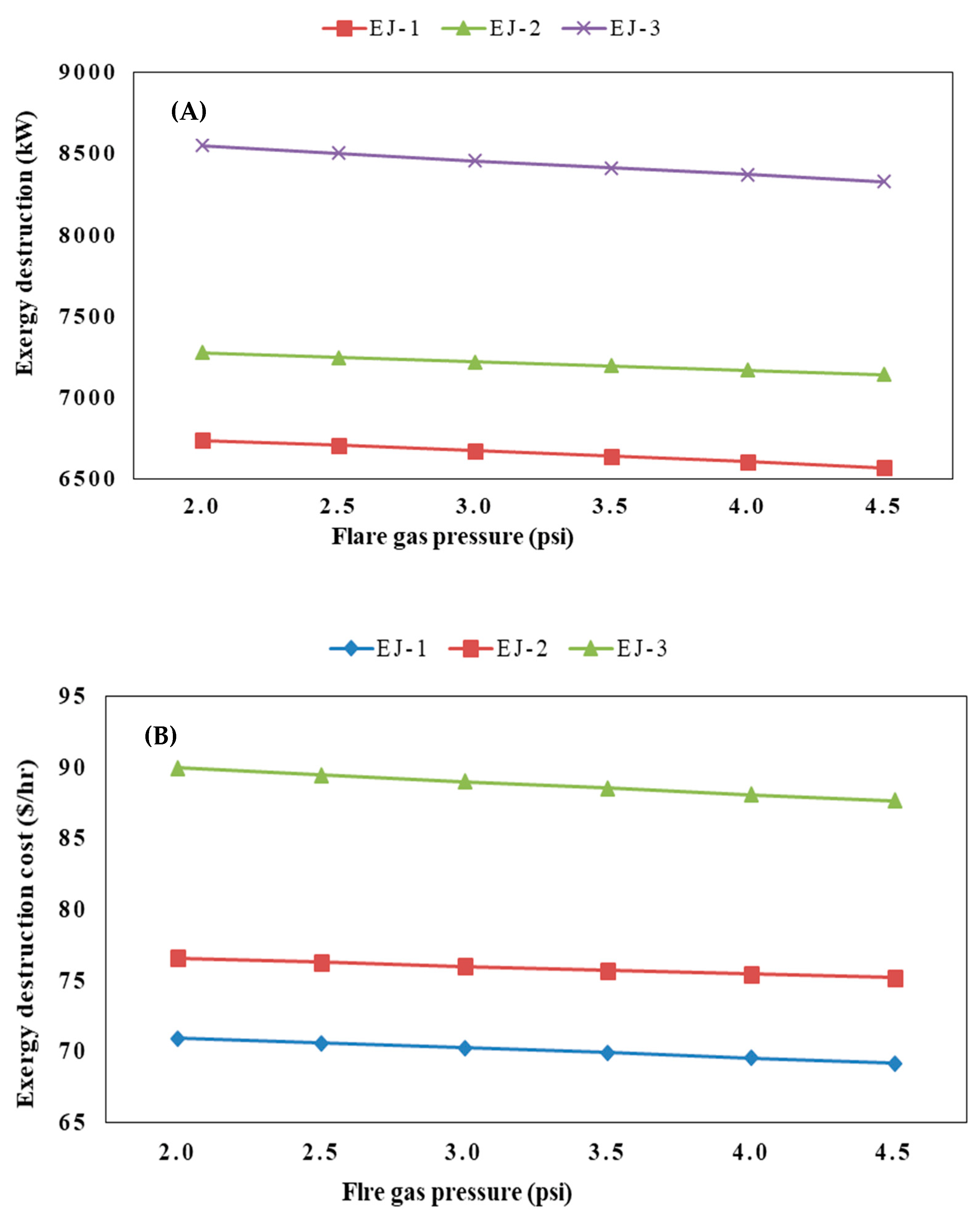
Sensitivity analyses of output parameters versus flare gas pressure are shown in Figure 5A–D. According to Figure 5A, exergy destruction of ejectors decreases when flare gas pressure rises. It happens due to the fact that when the flare gas pressure increases, the entrainment rate rises, which leads to a higher exergy in the outlet stream of the ejector. As a result, the exergy destruction falls. Figure 5B shows that, as flare gas pressure increases, the exergy destruction cost of ejectors reduces because the irreversibility of ejectors falls when flare gas pressure increases. According to Figure 5C, the exergoeconomic factor of ejectors has an upward trend when flare gas pressure rises. One reason is that equipment’s irreversibility cost is reduced compared with flare gas pressure increasing. According to Figure 5D, the ejectors’ relative cost differences are constant as flare gas pressure increases.

6. Conclusions

In this study, the application of a well-known process for the recovery of flare gas was studied in the Abadan refinery as a case study. By using Aspen Hysys we simulated a novel parallel ejector-compressor FGRS, to assess the process feasibility both technically and economically. Exergy and exergyeconomic analyses were performed for the new system. Results of exergy analysis showed that by totally consuming 450.14 kW as compression power and feeding natural gas to the system, 71% of input flare gas exergy can be recovered. Although injected natural gas pressure decreased from 210 psi to 60 psi, it is a beneficial characteristic for city and refinery energy consumers. In this system, ejectors have the highest exergy efficiency (99.87%) compared with other devices in the process, and their total exergy destruction rate is 8458.35 kW. The exergoeconomic analysis results are displayed in the form of exergy destruction cost and exergoeconomic factor, which are summarized here:
  • In exergy destruction cost, ejectors are the most important components since the highest exergy destruction cost in the system is that of the EJ-3 ejector, which is 89.01 USD/h;
  • From the exergoeconomic analysis, it can be deduced that the investment cost of air fans and compressors should be reduced due to their high exergoeconomic factor to reduce the system’s total cost;
  • The performance of the ejectors should be enhanced due to their low exergoeconomic factor to lower the total system cost. Moreover, the irreversibility of ejectors is very high compared with air fans and compressors.
By considering the above-mentioned modifications, this novel parallelized flare gas recovery system can be quite useful in reducing environmental impacts of gas flaring in industry.

Author Contributions

Conception and design of study, developing the idea, simulation, M.M.P.; acquisition of data, M.M.P., M.M., M.D., M.A. and M.N.; analysis and/or interpretation of data, Figure extractions, M.M.P., M.M. and M.N.; Supervision, A.R.; Writing manuscript, M.M.P., M.M. and M.N.; drafting the manuscript and team management, M.M.P., M.D. and M.A.; reviewing the manuscript, M.M.P., A.R., M.D. and M.A. All authors have read and agreed to the published version of the manuscript.

Funding

This research received no external funding.

Institutional Review Board Statement

Not applicable.

Informed Consent Statement

Not applicable.

Data Availability Statement

Not applicable.

Conflicts of Interest

The authors declare no conflict of interest.

Nomenclature

BLBook life ε Exergy Efficiency
cUnit exergy cost (USD/kJ)Superscripts
C ˙ Exergy cost rate (USD/h)CICapital investment
SEntropy (kJ/kg °C)OMOperating and maintenance
hEnthalpy (kJ/kg)Subscripts
CCCarrying charge0Index for first year of operation
CRFCapital recovery factoraAir
cwUnit cost of the generated electricity (USD/kWh) DDestruction
e Specific flow exergy (kJ/kg mole)FFuel
E ˙ Exergy rate (kW)iInlet
Ex Exergy (kW)kkth component
F Exergoeconomic factor (%)LLevelized
FC Fuel cost (USD/s)oOutlet
I Irreversibility (kW)PProduction
ieff Average annual discount rate (cost of money)totTotal
j jth year of operationAbbreviations
m ˙ Flow rate (kg mole/s)AC Air cooler
OMC Operating and maintenance costCCompressor
PEC Purchase equipment cost (USD)DFlash drum
Q ˙ Heat duty (kW)EJEjector
r Relative cost difference (%)TETee
rFC Annual escalation rate for the fuel costMIXMixer
rOM Annual escalation rate for the operating and maintenance costVExpansion valve
TRR Total revenue requirementPhPhysical
W Work transfer rate (kW)ChChemical
W ˙ Power (kW)FGRSFlare Gas Recovery System
Z ˙ kTotal cost rate of kth component including capital investment and operating–maintenance cost
Z ˙ CIRate of capital investment of kth component
Z ˙ K OM Rate of operating and maintenance cost of kth component
Greek letters
τ Annual operating hours (h)

Appendix A

Table A1. Exergy destruction and efficiency definitions for process equipment.
EquipmentExergy DestructionExergy Efficiency
Compressor I = Ex i Ex o = ( m ˙ . e ) i + w ( m ˙ . e ) o [34,35] ε = ( m ˙ . e ) i     ( m ˙ . e ) o W [34,36]
Ejector I = Ex i Ex o = ( m ˙ . e ) i ( m ˙ . e ) o [34,35] ε = ( m ˙ . e ) o ( m ˙ . e ) i [34,35]
Expansion valve I = Ex i Ex o = ( m ˙ . e ) i ( m ˙ . e ) o [34,35] ε = ( m ˙ . e ) o ( m ˙ . e ) i [34,35]
Air cooler I = Ex i Ex o = ( m ˙ . e ) i + e ai + w ( m ˙ . e ) o e ao [35,36] ε = ( m ˙ . e ) o   +   e ao ( m ˙ . e ) i   +   W [35,36]
Pump I = Ex i Ex o = ( m ˙ . e ) i + w ( m ˙ . e ) o [34,35] ε = ( m ˙ . e ) i     ( m ˙ . e ) o W [34,35]
Table A2. Economic constants and assumptions [16].
Economic ParametersValue
The average annual rate of the cost of money ( i eff )10%
Average nominal escalation rate for the operating and maintenance cost (rOMC)5%
Average nominal escalation rate for fuel (rFC)5%
Plant economic life (book life)25 years
Total annual operating hours of the system operation at full load7300
Table A3. FGRS investment costs and purchased equipment.
EquipmentŻ (USD/h)ŻOMC (USD/h)ŻCI (USD/h)
C-134.470.5833.89
C-217.280.2916.99
C-312.150.2011.94
AC-19.950.179.78
AC-29.660.169.50
AC-39.430.169.27
EJ-11.840.031.81
EJ-21.970.031.94
EJ-32.080.032.04

References

  1. Rahimpour, M.R.; Jokar, S.M. Feasibility of flare gas reformation to practical energy in Farashband gas refinery: No gas flaring. J. Hazard. Mater. 2012, 209, 204–217. [Google Scholar] [CrossRef]
  2. Rahimpour, M.; Jamshidnejad, Z.; Jokar, S.; Karimi, G.; Ghorbani, A.; Mohammadi, A. A comparative study of three different methods for flare gas recovery of Asalooye Gas Refinery. J. Nat. Gas Sci. Eng. 2012, 4, 17–28. [Google Scholar] [CrossRef]
  3. Soltanieh, M.; Zohrabian, A.; Gholipour, M.J.; Kalnay, E. A review of global gas flaring and venting and impact on the environment: Case study of Iran. Int. J. Greenh. Gas Control. 2016, 49, 488–509. [Google Scholar] [CrossRef]
  4. Fallah, T.; Belghaieb, J.; Hajji, N. Analysis and simulation of flare gas recovery in oil and gas producing company. Energy Sources Part A Recovery Util. Environ. Eff. 2019, 1–7. [Google Scholar] [CrossRef]
  5. Yazdani, E.; Asadi, J.; Dehaghani, Y.H.; Kazempoor, P. Flare gas recovery by liquid ring compressors-system design and simulation. J. Nat. Gas Sci. Eng. 2020, 84, 103627. [Google Scholar] [CrossRef]
  6. Comodi, G.; Renzi, M.; Rossi, M. Energy efficiency improvement in oil refineries through flare gas recovery technique to meet the emission trading targets. Energy 2016, 109, 1–12. [Google Scholar] [CrossRef]
  7. Haidl, J.; Mařík, K.; Moucha, T.; Rejl, F.J.; Valenz, L.; Zednikova, M. Hydraulic characteristics of liquid–gas ejector pump with a coherent liquid jet. Chem. Eng. Res. Des. 2021, 168, 435–442. [Google Scholar] [CrossRef]
  8. Mousavi, S.M.; Lari, K.; Salehi, G.; Torabi Azad, M. Technical, economic, and environmental assessment of flare gas recovery system: A case study. Energy Sources Part A Recovery Util. Environ. Eff. 2020, 1–13. [Google Scholar] [CrossRef]
  9. Ojijiagwo, E.; Oduoza, C.F.; Emekwuru, N. Economics of gas to wire technology applied in gas flare management. Eng. Sci. Technol. Int. J. 2016, 19, 2109–2118. [Google Scholar] [CrossRef] [Green Version]
  10. Khalili-Garakani, A.; Iravaninia, M.; Nezhadfard, M. A review on the potentials of flare gas recovery applications in Iran. J. Clean. Prod. 2021, 279, 123345. [Google Scholar] [CrossRef]
  11. Asadi, J.; Yazdani, E.; Dehaghani, Y.H.; Kazempoor, P. Technical evaluation and optimization of a flare gas recovery system for improving energy efficiency and reducing emissions. Energy Convers. Manag. 2021, 236, 114076. [Google Scholar] [CrossRef]
  12. Dincer, I.; Rosen, M.A. Exergy: Energy, Environment and Sustainable Development; Elsevier: Amsterdam, The Netherlands, 2020. [Google Scholar]
  13. Mohamadi-Baghmolaei, M.; Hajizadeh, A.; Zendehboudi, S.; Duan, X.; Shiri, H. Advanced exergy analysis of an acid gas removal plant to explore operation improvement potential toward cleaner production. Energy Fuels 2021, 35, 9570–9588. [Google Scholar] [CrossRef]
  14. Mohamadi-Baghmolaei, M.; Hajizadeh, A.; Zahedizadeh, P.; Azin, R.; Zendehboudi, S. Evaluation of hybridized performance of amine scrubbing plant based on exergy, energy, environmental, and economic prospects: A gas sweetening plant case study. Energy 2021, 214, 118715. [Google Scholar] [CrossRef]
  15. Mohamadi-Baghmolaei, M.; Hajizadeh, A.; Zendehboudi, S.; Duan, X.; Shiri, H.; Cata Saady, N.M. Exergy and Exergoeconomic Assessment of an Acid Gas Removal Unit in a Gas Refinery Plant. Ind. Eng. Chem. Res. 2021, 60, 14591–14612. [Google Scholar] [CrossRef]
  16. Mehrpooya, M.; Ansarinasab, H. Exergoeconomic evaluation of single mixed refrigerant natural gas liquefaction processes. Energy Convers. Manag. 2015, 99, 400–413. [Google Scholar] [CrossRef]
  17. Ghorbani, B.; Mehrpooya, M.; Hamedi, M.-H.; Amidpour, M. Exergoeconomic analysis of integrated natural gas liquids (NGL) and liquefied natural gas (LNG) processes. Appl. Therm. Eng. 2017, 113, 1483–1495. [Google Scholar] [CrossRef]
  18. Greyling, S.; Marais, H.; Van Schoor, G.; Uren, K.R. Application of exergy-based fault detection in a gas-to-liquids process plant. Entropy 2019, 21, 565. [Google Scholar] [CrossRef] [Green Version]
  19. Eghtesad, A.; Afshin, H.; Hannani, S.K. Energy, exergy, exergoeconomic, and economic analysis of a novel power generation cycle integrated with seawater desalination system using the cold energy of liquified natural gas. Energy Convers. Manag. 2021, 243, 114352. [Google Scholar] [CrossRef]
  20. Alirahmi, S.M.; Assareh, E. Energy, exergy, and exergoeconomics (3E) analysis and multi-objective optimization of a multi-generation energy system for day and night time power generation-Case study: Dezful city. Int. J. Hydrogen Energy 2020, 45, 31555–31573. [Google Scholar] [CrossRef]
  21. Zaresharif, M.; Vatani, A.; Ghasemian, M. Evaluation of Different Flare Gas Recovery Alternatives with Exergy and Exergoeconomic Analyses. Arab. J. Sci. Eng. 2022, 47, 5501–5520. [Google Scholar] [CrossRef]
  22. Hyprotech HYSYS v71.1 User Guide; Aspen Technology Inc.: Burlington, MA, USA, 2009.
  23. Vatani, A.; Mehrpooya, M.; Palizdar, A. Energy and exergy analyses of five conventional liquefied natural gas processes. Int. J. Energy Res. 2014, 38, 1843–1863. [Google Scholar] [CrossRef]
  24. Yazdanfar, J.; Mehrpooya, M.; Yousefi, H.; Palizdar, A. Energy and exergy analysis and optimal design of the hybrid molten carbonate fuel cell power plant and carbon dioxide capturing process. Energy Convers. Manag. 2015, 98, 15–27. [Google Scholar] [CrossRef]
  25. Rivero, R.; Rendón, C.; Gallegos, S. Exergy and exergoeconomic analysis of a crude oil combined distillation unit. Energy 2004, 29, 1909–1927. [Google Scholar] [CrossRef]
  26. Farshi, L.G.; Mahmoudi, S.S.; Rosen, M. Exergoeconomic comparison of double effect and combined ejector-double effect absorption refrigeration systems. Appl. Energy 2013, 103, 700–711. [Google Scholar] [CrossRef]
  27. Cengal, Y.A.; Boles, M.A. Thermodynamics: An Engineering Approach; Highstown McGraw Hill: Hightstown, NJ, USA, 1998. [Google Scholar]
  28. Institute, E.P.R. Technical Assessment Guide (TAG) Electricity Supply 1993; EPRI Palo Alto: Washington, DC, USA, 1993. [Google Scholar]
  29. Seshadri, K. Thermal Design and Optimization; Bejan, A., Tsatsaronis, G., Moran, M., Eds.; Wiley Interscience, John Wiley Sons Inc.: New York, NY, USA; Pergamon: Berlin, Germany, 1996. [Google Scholar]
  30. Lazzaretto, A.; Tsatsaronis, G. SPECO: A systematic and general methodology for calculating efficiencies and costs in thermal systems. Energy 2006, 31, 1257–1289. [Google Scholar] [CrossRef]
  31. Naderi, M.; Ahmadi, G.; Zarringhalam, M.; Akbari, O.; Khalili, E. Application of water reheating system for waste heat recovery in NG pressure reduction stations, with experimental verification. Energy 2018, 162, 1183–1192. [Google Scholar] [CrossRef]
  32. Couper, J.R.; Penney, W.R.; Fair, J.R.; Walas, S.M. Chemical Process Equipment: Selection and Design; Gulf Professional Publishing: Houston, TX, USA, 2005. [Google Scholar]
  33. Lazzaretto, A.; Tsatsaronis, G. On the quest for objective equations in exergy costing. In Proceedings of the ASME International Mechanical Engineering Congress and Exposition, Dallas, TX, USA, 16–21 November 1997; pp. 197–210. [Google Scholar]
  34. Tirandazi, B.; Mehrpooya, M.; Vatani, A.; Moosavian, S.A. Exergy analysis of C2+ recovery plants refrigeration cycles. Chem. Eng. Res. Des. 2011, 89, 676–689. [Google Scholar] [CrossRef]
  35. Vatani, A.; Mehrpooya, M.; Palizdar, A. Advanced exergetic analysis of five natural gas liquefaction processes. Energy Convers. Manag. 2014, 78, 720–737. [Google Scholar] [CrossRef]
  36. Mehrpooya, M.; Hossieni, M.; Vatani, A. Novel LNG-based integrated process configuration alternatives for coproduction of LNG and NGL. Ind. Eng. Chem. Res. 2014, 53, 17705–17721. [Google Scholar] [CrossRef]
Figure 1. The schematic of a flare gas recovery system with (A) liquid ring compressor (B) ejector.
Sustainability 14 09612 g001
Figure 2. Process flow diagram of the designed FGR system.
Sustainability 14 09612 g002
Figure 3. Cost balance.
Sustainability 14 09612 g003
Figure 4. Exergy destruction (A), exergy efficiency (B), exergy destruction cost (C), exergoeconomic factor (D), and relative cost difference (E) changes relative to recovered gas flow rate.
Sustainability 14 09612 g004aSustainability 14 09612 g004b
Figure 5. Exergy destruction (A), exergy destruction cost (B), exergoeconomic factor (C), and relative cost difference (D) variation versus flare gas pressure.
Sustainability 14 09612 g005aSustainability 14 09612 g005b
Table 1. Operating conditions of different streams of FGRS.
Stream No.Temperature (°C) Pressure (psi)Enthalpy (kJ/kg)Entropy
(kJ/kg °C)
Flow Rate
(kg/h)
1353−3853.110.97000
1a353−3853.110.95000
1b353−3853.110.92000
1c353−3853.110.92000
2353−3853.110.92500
2a353−3853.110.95000
2b353000
3353−3853.110.92500
44060−3846.29.62500
4a208.520−342511.12500
4b4020−3843.310.12500
4c101.540−3702.810.22500
4d4040−3844.79.72500
4e75.660−3765.19.82500
545.3210−4469.99.9463,716
645200−4469.99.9463,716
6a45200−4469.99.966,000
6b45200−4469.99.9132,000
6c45200−4469.99.9265,716
740.660−4466.610.5466,216
7a3915.9−4447.411.168,500
7b39.734.7−4462.210.7200,500
840.560−4463.310.5468,716
Table 2. Specifications of the air coolers and compressors.
EquipmentComponent NameHeat Duty (kW)Air Flow Rate (kg/h)Outlet Air Temperature (°C) Power (kW)
Air coolersAC-1−290.5422,80027.4432
AC-2−98.5424,00025.8326
AC-3−56.3424,20025.4721
EquipmentComponent NameAdiabatic Efficiency (%)Pressure RatioOutlet Temperature (°C)Power (kW)
CompressorsC-1756.67208.5297.26
C-2752101.597.6
C-3751.575.6155.28
Table 3. Exergy values of different streams in FGRS.
Stream No.Physical Exergy (kW)Chemical Exergy (kW)Total Exergy (kW)
1−416.8098,196.0497,779.04
1a−297.7170,140.0369,842.32
1b−119.0828,056.0127,936.93
1c−119.0828,056.0127,936.93
2−148.8635,070.0234,921.16
2a−297.7170,140.0369,842.32
2b000
3−148.8635,070.0234,921.16
4131.9935,070.0235,202.00
4a100.4235,070.0235,170.44
4b29.4235,070.0235,099.44
4c107.2135,070.0235,177.22
4d94.2235,070.0235,164.24
4e137.5435,070.0235,207.55
550,243.976,619,283.056,669,527.01
649,339.236,619,238.056,668,622.27
6a7022.3894,112.59949,134.97
6b14,044.761,884,225.181,898,269.93
6c28,272.093,792,945.283,821,217.38
726,895.536,654,292.386,681,187.91
7a241.06977,139.26977,380.32
7b7074.402,861,354.502,868,428.89
827,026.776,689,313.736,716,340.50
Table 4. The cost estimation equations of each equipment [32].
EquipmentCost Estimation Equations
CompressorPECC = 7900(HP)0.62
Air coolerPECAC = 30(A)0.4
EjectorPECEJ = 13.3(f1f2f3X0.41)
Table 5. Main cost balance equations for FGRS.
EquipmentMain EquationsEquipmentMain Equations
EJ-1Ċ3 + Ċ6a + ŻEJ1 = Ċ7aC-1Ċ2 + ĊW-C1 + ŻC1 = Ċ4a
EJ-2Ċ7a + Ċ6b + ŻEJ2 = Ċ7bC-2Ċ4b + ĊW-C2 + ŻC2 = Ċ4c
EJ-3Ċ7b + Ċ6c + ŻEJ3 = Ċ7C-3Ċ4d + ĊW-C3 + ŻC3 = Ċ4e
TE-1Ċ1 = Ċ1a + Ċ1bAC-1Ċ4a + ĊW-AC1 + ŻAC1 = Ċ4b
TE-2Ċ2a = Ċ2 + Ċ3AC-2Ċ4c + ĊW-AC2 + ŻAC2 = Ċ4d
TE-3Ċ6 = Ċ6a + Ċ6b + Ċ6cAC-3Ċ4e + ĊW-AC3 + ŻAC3 = Ċ4
Mix-1Ċ4 + Ċ7 = Ċ8
Table 6. Auxiliary cost balance equations for FGRS.
EquipmentAuxiliary Equations
TE-1(Ċ1a/Ė1a) = (Ċ1b/Ė1b)
TE-2(Ċ2/Ė2) = (Ċ3/Ė3)
TE-3(Ċ6a/Ė6a) = (Ċ6b/Ė6b) = (Ċ6c/Ė6c)
Table 7. Unit exergy cost of FGRS streams.
Flow No.C (USD/Gj)Ċ (USD/h)
11.220429.4
1a1.220306.7
1b1.220306.7
1c1.220306.7
200
2a1.220153.4
2b1.220306.7
300
41.220153.4
4a2.320294.1
4b1.695214.7
4c1.8227.5
4d2.003253.6
4e2.098265.6
52.231282.7
62.92370,182
6a2.92370,182
6b2.9239989
6c2.92319,978
72.92340,215
7a2.92570,341
7b2.88310,144
82.91730,124
Table 8. Results of exergy analysis of FGRS.
EquipmentĖF (kW)ĖP (kW)ĖD (kW)ε (%)
C-1297.26249.2847.9983.86
C-297.6077.7919.8179.70
C-355.2843.3211.9678.36
AC-1132.42120.421290.94
AC-2133.21121.2211.9991
AC-3158.54143.9914.5590.82
EJ-1984,056.13977,380.326675.8199.32
EJ-22,875,650.252,868,428.897221.3699.75
EJ-36,689,646.276,681,187.918458.3599.87
Table 9. Results of exergyeconomic analysis of FGRS.
EquipmentĖD (kW)CF (USD/Gj)CP (USD/Gj)ĊD (USD/h)Ż (USD/h)ε (%)r (%)f (%)
C-147.9919.7261.923.4134.4783.86214.0191
C-219.8119.7286.441.4117.2879.70338.3492.47
C-311.9619.72103.050.8512.1578.36422.5993.47
AC-11219.7244.630.859.9590.94126.3192.11
AC-211.9919.7243.810.859.6691122.1491.90
AC-314.5519.7239.901.039.4390.82102.3190.12
EJ-16675.812.922.9470.251.8499.320.72.55
EJ-27221.362.922.9375.991.9799.750.262.53
EJ-38458.352.922.9389.012.0899.870.132.28
Publisher’s Note: MDPI stays neutral with regard to jurisdictional claims in published maps and institutional affiliations.