Abstract
Electrochemical energy storage stations (EESSs) have been demonstrated as a promising solution to mitigate power imbalances by participating in peak shaving, load frequency control (LFC), etc. This paper mainly analyzes the effectiveness and advantages of control strategies for eight EESSs with a total capacity of 101 MW/202 MWh in the automatic generation control (AGC) in the power system of the Jiangsu power grid. Firstly, an adaptive tracking strategy for electricity quantity that considers the state of charge (SOC) of EESSs is proposed to calculate the baseline power of the EESS participating in AGC. This strategy can simultaneously coordinate different time scale application requirements, such as peak shaving and LFC. Then, an adaptive strategy for regulation requirement allocation among AGC control groups with EESSs that considers different area regulation requirements (ARRs) is proposed to calculate the regulation power of EESS participating in AGC. This strategy can realize the balance transfer of fast and slow regulation capacity, ensure the complementary advantages of various frequency regulation resources and improve the dynamic regulation performance of the control area. Finally, the proposed strategy is validated via a test system to confirm its effectiveness and advantages, as well as via a quantitative analysis on the improvement of the control performance standard (CPS) of the Jiangsu power grid with the participation of EESSs in AGC.
1. Introduction
In recent years, with the increasing maturity and economy of electrochemical energy storage technology, the electrochemical energy storage station (EESS) has been rapidly developed and constructed in many countries and regions to improve the flexibility and resilience of power systems [1]. In 2022, the total capacity of ten grid-side EESSs in the Jiangsu power grid, China, that were invested in by electric power corporations has reached 227 MW/454 MWh. Compared with conventional power regulation resources, such as thermal and hydropower units, the EESS has been confirmed as a promising resource for power systems due to its high control flexibility and fast response speed [2]. In practical application scenarios, EESSs are mainly utilized to mitigate multi-time-scale power imbalances. For long time scale applications, EESSs can be utilized for peak-load shifting [3]. For short time scale applications, EESSs can participate in emergency active power support [1] and load frequency control (LFC) [4,5], etc.
Frequency regulation is an auxiliary service that plays a significant role in maintaining the security and stability of power system operation. The units undertaking frequency regulation should respond to the active power output command assigned by the LFC or automatic generation control (AGC) system in a timely and precise manner. Conventional thermal units with large mechanical inertias and long response time delays are inappropriate to undertake short-term frequency regulation demand [6]. Furthermore, frequent and reciprocal regulation leads to the wear and tear of units. These restrict further improvements in system security and power quality. EESSs are capable of making responses with rapidity and precision, which present a suitable solution to the short-term imbalance in power supply and demand [7]. According to a comparative analysis on the frequency regulation resources of the United States’ electricity market, the effectiveness of EESSs in frequency regulation is 1.7 times that of hydropower units, 2.5 times that of gas-fired power units, and over 20 times that of coal-fired units [8]. Compared with conventional frequency regulation resources, EESSs have shown remarkable advantages. Hence, large-scale EESS participation in power system frequency regulation has recently attracted considerable attention [9,10,11,12].
Scholars around the world have conducted fruitful research on the EESS participating in AGC. In order to mitigate the fatigue and economic problems of conventional units by providing frequency regulation services and improving their response delay in frequency regulation, a few studies [9,10,11,12] have proposed a coordinated operation method for EESS and conventional units. Zhong et al. [9] divided the area regulation requirement (ARR) into the normal regulation zone, alert zone, and contingency zone. Then, ARR is dispatched to the EESS, vehicle-to-grid (V2G) and conventional frequency regulation resources according to different priorities. Cheng et al. [10] proposed a frequency regulation demand dispatching strategy based on the dynamic available AGC of the EESS and utilized unfiltered, independent area control error (ACE) to control the EESS. Liu et al. [11] and Guzman et al. [12] utilized discrete Fourier transformation to analyze high-frequency and low-frequency regulation demand to formulate a control strategy for EESS to participate in system frequency regulation. Taking into account the requirements of power grid frequency control and the limiting factors of EESS capacity, a self-adaption control strategy of frequency regulation that considers the SOC of EESSs is proposed in [13], as well as time domain evaluation indices of EESSs participating in frequency regulation. Based on the analyses of power system frequency regulation requirements, a method in [14] is proposed to quantify the low and high frequency components of the regulation requirements using a discrete Fourier transform. Then two control strategies are presented for EESSs participating in AGC according to their fast response merits.
In addition, EESS control in LFC aims to enhance frequency responses by providing active power support with a conventional model-based controller. In [15,16], the control method of large-scale grid EESSs to mitigate power imbalances by a frequency regulation scheme is investigated. However, the cost of EESS degradation is rarely considered with model-based controllers. With fast speeds and strong learning abilities, data-driven methods have become desirable alternatives for both EESS modelling [17] and control support [18,19]. Nevertheless, the existing data-driven control methods still ignore battery degradation. Deep reinforcement learning based on the critic–actor model [20] provides a promising solution.
Given the frequency regulation demand after the integration of multiple energy storage systems, the Jiangsu electric power dispatch center has established a multi-time-scale regulation and operation system for the EESS, with technical support from provincial and prefecture levels of dispatch. A multi-scenario application and a control framework for dispatching considering EESS, division of control and control area have been formulated. This paper analyzes the effectiveness of strategies for eight 101 MW/202 MWh grid-side EESSs in Zhenjiang city, Jiangsu province, participating in the AGC power system. Firstly, three operation modes of newly constructed EESSs participating in the AGC of the Jiangsu power grid are introduced. Then, an AGC strategy with adaptive baseline power considering the state of charge (SOC) of energy storage is proposed, including an adaptive baseline power calculation and strategies for regulation requirement allocation among the AGC control groups with EESSs. Finally, the proposed strategy is validated via a quantitative analysis of the enhancement in the power system control performance standard (CPS) [21] with EESSs participating in the AGC. The results show that compared with conventional units, the EESS is capable of providing better frequency regulation services that can effectively improve the overall efficiency and economy of system AGC.
The contributions of this study are as follows:
- (1)
- The operation and control strategies of the EESS which can simultaneously coordinate different time-scale application requirements, including network peak-load shifting and ACE regulation, are formulated. Furthermore, all proposed control modes of the EESS can take into account the frequency regulation requirements.
- (2)
- In view of the disadvantages of conventional peak shaving control, the adaptive tracking of electricity quantity considering the SOC of EESSs is proposed to improve the efficiency of EESSs and slow down the processes of battery degradation. Furthermore, this strategy solves the problems that the power grid regulation performance is reduced and the SOC of EESSs is easy to deviate from the ideal operating area when the capacity proportion of EESSs is large.
- (3)
- The control group of EESSs is designed and added to participate in ACE regulation of the Jiangsu control area together with the control groups of the coal-fired units and gas-fired power units. Furthermore, this paper proposes the frequency regulation strategy of multiple resources considering EESSs, including the control group dispatching principle, and the regulating volume transfer and balance method.
The remainder of this paper is organized as follows. Section 2 describes an overview of EESSs in the Jiangsu power grid. A multi-time-scale active power control framework of EESSs and a multi-scenario active power control strategy design for EESS participating in the AGC of the Jiangsu power grid are proposed in Section 3 and Section 4, respectively. In Section 5, case studies and the results analysis are presented. Finally, in Section 6, the main conclusions are summarized.
2. Overview of EESSs in the Jiangsu Power Grid
At present the Jiangsu power grid contains coal-fired units (79.5 GW), gas-fired power units (17 GW), nuclear power units (5.5 GW) and renewable energy units (34 GW), and the total generation capacity is approximately 136 GW. In July 2021, the maximum load of the Jiangsu power grid reached 120 GW. In March 2018, because the original planned gas-fired power plant in Zhenjiang City, Jiangsu Province, could not be put into operation on schedule, it was expected that there would be a power shortage of 100 MW in the Zhenjiang power grid during the summer peak demand of 2018.
Therefore, the Jiangsu electric power corporation decided to invest eight grid-side EESSs with a total installed capacity of 101 MW/202 MWh in the Zhenjiang power grid and complete their construction in July 2018 before tiding over the summer peak demand [22]. The geographical distribution of eight EESSs is shown in Figure 1. In 2019, the Jiangsu electric power corporation continued to strengthen the construction of grid-side EESSs, and built multiple grid-side EESSs in many regions of Jiangsu province, China. Up to now, the number of EESSs has reached 10 and their capacities have been more than 227 MW/454 MWh.
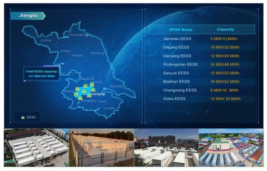
Figure 1.
The geographical distribution of eight grid-side EESSs with a total capacity of 101 MW/202 MWh in the Jiangsu power grid, China, with an investment from the Jiangsu electric power corporation.
3. Multi-Time-Scale Active Power Control Framework of EESSs in the Jiangsu Power Grid
Since the EESSs in the Jiangsu power grid were put into operation in July 2018, they have participated in multi-time-scale auxiliary services, such as emergency response, primary frequency control, LFC, peak-load shifting, etc. Emergency response and primary frequency control are monitored and implemented by the power conversion system (PCS) and battery management system (BMS) of the EESS on site, and their response times are on the millisecond scale. LFC and peak-load shifting are implemented by remote control of the AGC, and their regulating commands are transferred from the energy management system (EMS) of the Jiangsu electric power dispatching and control center to the supervisory control and data acquisition (SCADA) system of the EESS.
Conventional AGC mainly aims at coordinating the power output of different units according to the optimal dispatching principles while ensuring the quality of power system frequency and the implementation of the tie–line power exchange plan [23]. In this paper, the EESS can participate in system ACE regulation, the elimination of network security constraints, and peak shaving services by responding to the AGC command assigned by the higher dispatching system. The SCADA system of the EESS can generate the station-side AGC command in a real-time manner according to the dispatched AGC command and the current state of each battery cell so that the EESS can track the AGC command while ensuring the security of batteries operation.
The procedure of EESS receiving the dispatching command and participating in AGC regulation is illustrated in Figure 2, which consists of the dispatching master station, the dispatching data network, and the SCADA system of the EESS. The active power control modes of the EESS at a top-down priority include local control (emergency response, primary frequency control), remote control of AGC, and local autonomous control. Eight gird-side EESSs in the partitioning power network of Fangjin are aggregated to participate in the 220 kV power transmission profile adjustment and cooperate to cut the transmission line flow under peak load. Moreover, these EESSs participate in peak-load shifting or frequency regulation together. Under the scenario of peak-load shifting, the unit commitment and economic dispatch models are used to determine the day-ahead schedule of EESSs, including their charging and discharging periods.
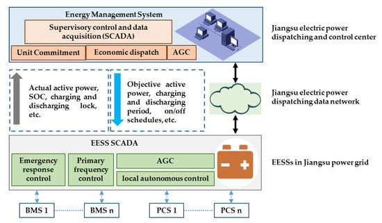
Figure 2.
Two-level hierarchical active power control framework of EESSs in the Jiangsu power grid.
The AGC function module of EESSs at the dispatching master station side is operated on the EMS. This module collects the real-time active power and SOC data uploaded by the EESSs and directly controls the EESSs according to the requirements of peak-load shifting, the elimination of network security constraints, and ACE regulation. For peak-load shifting, the unit commitment and economic dispatch function module of the dispatching master station generate the suggested scheduling curve of the EESS in the next 24 h according to the load and renewable generation prediction data. Moreover, the unit commitment and economic dispatch models are used to determine the day-ahead schedule of EESSs, including their charging/discharging period in the conventional peak shaving control in Section 4.2.1 or the control schedule of EESSs in adaptive tracking of electricity quantity in Section 4.2.3. Then, the scheduling curve of each EESS is sent to the AGC function module for determining the AGC baseline command of the EESS. The set point of active power and the on/off schedules for each EESS are calculated in real time and sent to the stations that participate in AGC. Communication between the EESSs participating in AGC and the dispatching department is via the dispatching data network. The EESSs upload the real-time data related to AGC and receive the active power control command assigned by the dispatching master station. The SCADA of the EESS allocates the power command according to the control mode and operation status of the EESS and sends that to PCS for execution.
4. Multi-Scenario Active Power Control Strategy Design for EESS Participating in AGC of the Jiangsu Power Grid
According to the multi-scenario application requirements of large-scale EESS-integrated power systems dispatching and control, this section firstly proposes the control mode for the EESS at the side of the dispatching master station, the regulation resources aggregation analysis, the dispatching of the partitioning power network, and the frequency regulation strategy in control area. Furthermore, the regulation objective of the EESS that takes into account both the electric quantity trend adjustment and power balance control is formed through hierarchical decision making.
4.1. Control Mode of EESS Participating in AGC of the Jiangsu Power Grid
The control mode of the EESS determines its power regulation strategy and control behavior. According to the excellent power regulation performance of the EESS and its constrained battery capacity, the following control modes are designed at the dispatching master station side.
4.1.1. Charging Model (CHRG)
The charging of the EESS is carried out with the maximum available charging power as the objective until the SOC of the EESS reaches the upper limit. The ACE value of the control area can be taken into account, and the charging power can be reduced to avoid worsening the power balance of the control area.
4.1.2. Discharging Model (DISC)
The discharging of the EESS is carried out with the maximum available discharging power as the objective until the SOC of the EESS reaches the lower limit. The ACE value of the control area can be taken into account, and the discharging power can be reduced to avoid worsening the power balance of the control area. The charging and discharging modes are not only used for daily charging and discharging dispatching of the EESS, but also for emergency regulation in the case of the elimination of network security constraints, fault power recovery and so on.
4.1.3. Scheduling Tracking Model (SCHE)
The EESS tracks the scheduling plan and assists in the frequency regulation of the control area on the basis of the scheduling plan. The scheduling plan of EESSs in the next 24 h can be formulated uniformly by the unit commitment and economic dispatch function module of the dispatching master station according to the peak-load shifting requirements or determined by the EESS itself according to the peak-valley characteristics of the load, peak-valley electricity price or the profit requirements of the EESS.
4.1.4. Baseline Tracking Model (BASE)
The EESS tracks the set baseline value of active power and assists in the frequency regulation of the control area on the basis of active baseline power. The baseline value of active power of the EESS can be derived from the manual setting value or calculated allocations of the AGC module.
In addition, according to the different regulation responsibilities of the EESS participating in frequency regulation of the control area, the regulation mode of the EESS is further divided into four types, including off-regulation (O), normal regulation (R), assistant emergency regulation (A) and emergency regulation (E), and the EESS will participate in the unbalanced power regulation under the four regulation modes for different ACE values. The control modes of the EESS, such as SCHE and BASE, can be combined into various groups of control modes, including BASEO/BASER/BASEA/BASEE and SCHEO/SCHER/SCHEA/SCHEE. Among them, BASEO and SCHEO mean that the EESS only tracks the given baseline value of active power or the baseline power of the scheduling plan, while other modes mean that the EESS participates in the ACE adjustment on the basis of tracking the baseline power.
As shown in the Figure 3, the objective power of the EESS i at the moment t should consist of two parts: the baseline power and the regulating power . The baseline power of the EESS usually considers the peak shaving in the control area, the clustering objective tracking in partitioning power network, the adaptive tracking of electricity quantity and so on. The regulating power is only responsible for the active power balance control of the control area. The objective power of the EESS is defined as follows:

Figure 3.
The two parts of objective power of EESSs in the Jiangsu power grid.
4.2. The Baseline Power Calculation of EESS Participating in AGC of the Jiangsu Power Grid
4.2.1. The Baseline Power Calculation of EESS Considering Charging and Discharging Plans for EESS
Given the difference in peak and valley electricity prices of EESSs, the peak shaving control is designed considering the economy of EESS operations. At the valley price, the storage only charges; at the peak price, the storage only discharges. The peak shaving control is implemented when tiding over the summer peak load in 2018 and the EESSs are charged and discharged twice per day when participating in peak-load regulation. As shown in Table 1, the charging and discharging statuses of EESSs are basically consistent with the present time-of-use (TOU) electricity price of the industrial peak–valley load in Jiangsu Province. All EESSs were operated according to the charging/discharging curves assigned by the day-ahead scheduling implemented on the unit commitment and economic dispatch function module of EMS. During the summer peak season, the total number of charging and discharging times are 157 and 149, respectively. The overall efficiency of EESSs is about 84%.

Table 1.
The charging and discharging statuses of EESSs over all scheduling periods.
Based on the linear interpolation method, the day-ahead charging and discharging plan of EESS during the scheduling period is interpolated according to K segment per minute to determine the baseline power of EESS for peak shaving control, and the calculation formula is as follows:
where and are respectively the charging and discharging powers of the EESS during the scheduling period t, and is the baseline power in the segment k after the interpolation of the charging and discharging plan of the EESS i during the scheduling period t, and k meets the criteria . If the plan value contains 96 points a day, then each scheduling period is 15 min. Interpolation is performed 12 periods per minute (5 s interval) and k meets the criteria . Linear interpolation of charge and discharge plan of EESS is shown in Figure 4.
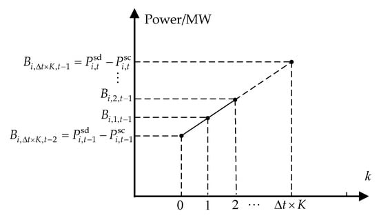
Figure 4.
Linear interpolation of charge and discharge plan of EESS.
4.2.2. The Disadvantages of Conventional Peak Shaving Control
As described above, the EESSs are operated under the SCHER mode in which the value scheduled by the “charging and discharging twice per day” strategy is set as the baseline power for participating in ACE regulation. However, the EESSs kept operating at the lower and upper SOC limits 25–90%, as shown in Figure 5, and deviated from the expected operating range. As a result, the EESSs were incapable of providing favorable frequency regulation service and the performance and life span of the EESSs deteriorated. Therefore, the scheduling value should be constantly adjusted so that the actual operating range of EESSs can entirely cover the expected one.
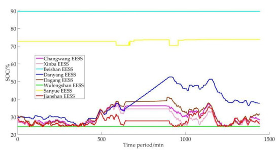
Figure 5.
SOC curves of EESSs under peak shaving control on 3 August 2018.
Therefore, the control schedule during peak regulation hours is determined, including the charging/discharging states of EESSs and the targeted SOC (i.e., the expected upper and lower SOC limits of EESSs), as shown in Table 2 and Figure 6. Then, the baseline power of EESSs is calculated every twenty seconds according to the current SOC and the targeted SOC of the scheduling time span. For example, because the baseline power is adaptively regulated, the SOC at the end of the time span between 2:00 and 5:00 reached 75%. It should be noted that the four time spans in Table 2 are discontinuous. During the undefined time span, the baseline power is set as 0 and the targeted SOC is excluded.

Table 2.
Control schedule of EESSs during typical peak regulation hours.
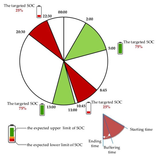
Figure 6.
Tracking of electricity quantity during typical peak regulation hours.
However, the predefined typical peak regulation hours have poor adaptability of the trend of load, especially in extreme weather or during holidays. The predefined peak valley and actual peak valley are easy to mismatch, which may lead to the SOC of the EESS deviating from the expected target and being unable to reserve enough electric quantity in the subsequent power grid peak shaving period.
Therefore, the control strategy with adaptive baseline power considering the SOC of EESS is proposed. Since 17 November 2018, the EESSs have operated in the BASER mode. When participating in AGC, the objective power of the EESS is set as the baseline power added to the regulation power. When the participation is terminated, the EESSs should charge and discharge the spare regulation power as soon as possible during the ARR dead band.
In addition, the control mode of EESSs generally adopted BASER or BASEE with zero power as the baseline power in the present engineering. Under the influence of charging and discharging efficiency and self-discharge, the long-term frequency regulation of the battery will lead to a gradual decrease in the SOC and battery degradation. Therefore, according to the load characteristic or peak–valley electricity price, the active power energy management with peak–valley electricity transfer can be realized by dynamically adjusting the baseline power to ensure that the electricity recovery of EESSs matches the demand of the power grid.
4.2.3. Adaptive Tracking of Electricity Quantity Considering SOC of EESS
- (1)
- The baseline power calculation of adaptive tracking of electric quantity considering the SOC plan of EESS
The unit commitment and economic dispatch models are used to determine the day-ahead schedule of the EESS, including their charging and discharging plans. Furthermore, the SOC plan values of EESSs are determined via their charging and discharging plans. It is assumed that the initial SOC value of the EESS i is , and after discharging for a time of t and power the SOC of EESS i is calculated as follows:
where is the SOC plan of EESS i and is the rated capacity of the EESS (MWh). When the EESS only tracks the charge and discharge plans and does not participate in frequency regulation, the SOC plan of the EESS can be estimated by Equation (3).
The adaptive baseline power is calculated by (4):
where is the baseline power for responding to the power command dispatched to the EESS i, is the SOC at the moment t, is the targeted SOC of the corresponding time span at the moment t, is the rated capacity of the EESS i, is the energy transfer efficiency of the EESS i and meets the criteria , and is the difference between the moment t and the end of the corresponding time span. When , the baseline power is negative and the EESS i charges; when , the baseline power is positive and the EESS i discharges.
Moreover, to ensure the effectiveness of SOC control, the regulation range and method of EESSs should be adjusted online.
- (a)
- The buffering time in Table 2 is for the final checking of the electricity. During the buffering time, the EESS i adjusts the charging/discharging limits according to the difference between and . If , the discharging is disabled; if , the charging is disabled.
- (b)
- If is greater than the maximum discharging power, the EESS i only discharges; if is smaller than the maximum charging power, the EESS i only charges.
- (2)
- Adaptive correction method of electricity
When the EESS participates in frequency regulation, its SOC will deviate from the planned value. In order to avoid frequent power oscillation caused by over-tracking the SOC plan, the SOC of EESS is allowed to deviate moderately from the plan. Only when the following conditions are met, the EESS will enter the electricity correction link. The baseline power of EESS is calculated by Equation (4).
- (a)
- When and , the SOC plan trend of the EESS is increasing. If , the EESS needs to be charged to correct the electricity;
- (b)
- When and , the SOC plan trend of the EESS is decreasing. If , the EESS needs to be discharged to correct the electricity.
where and are respectively the rated charging and discharging powers of the EESS.
In other cases, the EESS takes zero power as the baseline power, and at the same time, according to the baseline power in (4), in order to ensure the SOC tracking effect, if is greater than the maximum discharge power, the EESS will only be discharged but not charged, and if is less than the maximum charging power, then the EESS can only be charged and not discharged.
4.3. The Regulation Power Calculation of EESS Participating in AGC of the Jiangsu Power Grid
4.3.1. Description of CPS Standard
The North American Electric Reliability Council (NERC) proposed the CPS standard containing the CPS1 and the CPS2 to replace the A1 and A2 criterion in 1998 [19]. Instead of requiring ACE to cross zero at least once every ten minutes, CPS1 takes a more reasonable approach based on statistical theory. First, an Expression (5) is identified which represents, quantitatively, a control area’s contribution to the reliability objective of the interconnected system to which it belongs:
where is the clock-minute average of the ACE of area i that is required to sample every two seconds and then take the average of thirty values, is the CPS1 control target of the root mean square of the annual 1 min frequency average deviation of the interconnected system (0.018 Hz in the Jiangsu power grid), is the clock-minute average of frequency deviation (in Hz) that is required to sample every one second and then take the average of sixty values, and is the frequency bias of the control area i (−1072.5 MW/0.1 Hz in the Jiangsu power grid).
When the value is negative, it means that the control area is over-transmitted at a low frequency (less reception) or under-transmitted at a high frequency (over-received) in one minute and the control area is helping the interconnection’s regulation requirement; when the value is positive, it means the control area is over-transmitted at a high frequency (less reception) or under-transmitted at a low frequency (over-received) in one minute and the control area is acting as a burden to the interconnection’s regulation requirement.
The statistical Formulas (6) and (7) of the CPS1 (calculated as ) for a certain period of time (such as 10 min, 1 h, …, even 1 month, 1 year) are defined as follows:
where n is the number of minutes. The CPS1 standard requires that each control area must have no less than 100% compliance. The CPS standard is implemented in the East China power grid composed of the Jiangsu power grid, Shanghai power grid, Zhejiang power grid, Anhui power grid and Fujian power grid.
It can be seen from Equation (5) that the ideal AGC control strategy must consider simultaneously ACE and , and keep the signs of and opposite; that is, CPS1 ≥ 200%. Therefore, the ideal control effect under the CPS standard is shown in Figure 7.
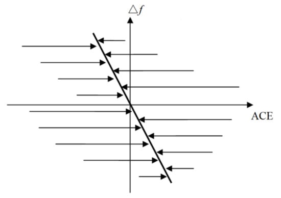
Figure 7.
Ideal control effect under CPS standard.
As shown in Figure 6, in order to realize the ideal control strategy under the CPS standard, it is necessary to add a component proportional to the frequency deviation in the ARR , namely:
where is the proportional component in ARR, and is the integral component in ARR. is the CPS component in ARR, also known as CPS regulation power, and is introduced specifically for the CPS control strategy. is the proportional gain coefficient to ensure the ACE crosses zero, and can be directly set to 1 under the CPS control strategy. is the filtered ACE value. is the integral gain coefficient. is the accumulated ACE integral value of the current assessment period (such as 10 min), in MWh. is the frequency gain coefficient, in MW/0.1 Hz. is the filtered frequency deviation, in Hz.
4.3.2. Allocation Strategy for Control Groups of AGC
The control group of the EESS is added to participate in the ACE regulation of Jiangsu control area together with the control groups of the coal-fired unit and gas-fired power unit. The time when the control group of the EESS participates in ACE regulation can be determined by setting the control group parameters, such as group regulation mode (normal or emergency mode), positive/negative emergency threshold and the increase/decrease priorities among the groups. The EESS participates in the ARR allocation of its affiliated group. In addition, the partitioning attribute of the EESS is added to control the power flow of transmission lines in the partitioning power network of Fangjin. The corresponding relationship among the partitioning power network, the EESS, the control group of the EESS and the control area is shown in the Figure 8.
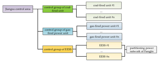
Figure 8.
The corresponding relationship among the partitioning power network, the EESS, the control group of the EESS and the control area.
According to the absolute value of ARR, dividing ARR into different regulation regions, including dead band, normal regulation region, assistant emergency regulation region and emergency regulation region, can more precisely characterize the power grid operating state and the demand for the amount of frequency regulation resources. Therefore, by analyzing the relationship between the response characteristics of the EESS and the conventional units and regulation requirements, and comprehensively considering EESS capacity constraints, the operating range of the SOC and power grid frequency regulation requirements, the output contribution and intervention boundaries of EESSs participating in frequency regulation are analyzed, and thus a cooperative control strategy considering ARR regions is proposed. This strategy helps to realize the complementary advantages of EESSs and conventional units.
- (1)
- Dead band
According to the classification rules of ARR regions, the variation in ACE within the dead region is small, and usually fluctuates around the zero value. Such high-frequency and low-amplitude regulation signals are very unfriendly to conventional units with time delays in response, which will increase their mechanical wear and affect their service life and economy. The EESS has a fast response speed, and the charging and discharging operating conditions of the EESS are easy to change. The regulation requirements of shallow charging and shallow discharging in the dead band of ARR are a good match for the response characteristics of the EESS. Therefore, the EESS is designed to respond to the regulation demand contributing to SOC recovery, which not only reduces the probability of the ACE continuing to expand into the normal regulation region, thereby reducing the number of actions of conventional units, but also realizes the optimal management of the SOC.
The regulation demand of the EESS control group in the dead band is calculated as follows:
- (2)
- Normal regulation region
Considering that the direction of area control demand varies frequently under inconsistent power deficiency, the EESS participates in AGC during contingencies or when the regulation capacity of other units is insufficient in order to prevent the waste of EESS regulation capacity on the ARR, which stays positive or negative and constantly changes the ramp load that is mainly handled by the gas-fired power and the coal-fired units rather than the EESSs with limited capacity. The frequency regulation resources within the control area are categorized into coal-fired units, gas-fired power units and EESSs, as shown in Table 3. These units are dispatched in a priority-based order when there is available regulation capacity, and the timing when participating in regulation is determined by the activation threshold. The “unit control mode” is the control mode normally utilized by the units. The EESSs utilize the BASER or the SCHER modes. The gas-fired power units utilize the contingency-oriented SCHEE mode due to the limited natural gas capacity. The coal-fired units utilize the AUTOR mode.

Table 3.
Unit types and their control strategies.
In practice, the participation of units in AGC is determined by priority, the unit control mode, and the available regulation capacity [24]. The arrangement of different regulation resources in priority order is shown in Figure 9. In the normal regulation region, the EESSs joined in to cooperate with the coal-fired units for regulation in order to take full advantage of their limited capacity and superior regulation performance.
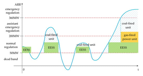
Figure 9.
Arrangement of regulation undertaken by different units.
The ARR-to-be-dispatched can be formulated as follows, which is equal to the difference between the total ARR determined in (8) and the power-to-be-regulated of unready units and is calculated every five seconds:
where is the current unregulated power of unit i in the same regulated direction with ARR at the moment t.
The priority among units is grid-side EESSs, gas-fired power units and coal-fired units.
- (a)
- The total amount of to-be-dispatched of grid-side EESSs is equal to the ARR to-be-dispatched , which can be formulated as:
- (b)
- The total amount of to-be-dispatched of gas-fired power units is equal to the ARR to-be-dispatched minus the actual dispatched amount of grid-side EESSs, which can be formulated as:
- (c)
- The total amount of to-be-dispatched of coal-fired units is equal to the total amount to-be-dispatched of gas-fired power units minus the actual dispatched amount of gas-fired power units:
Moreover, the maximum available increasing/decreasing capacity of EESSs is the sum of the of each EESS. The maximum available increasing/decreasing capacity of a single EESS is usually its regulation step per minute within the regulation range of the EESS when the EESS has regulated in place and the ARR exceeds the dead band.
- (3)
- Assistant emergency regulation/emergency regulation region
In the assistant emergency/emergency regulation region, the regulation demand is large and the duration is long. The support depth and support duration of frequency regulation resources are required to be higher. According to the grouping priority control mode of the normal regulation region, the EESS, as a resource with limited capacity, will continue to fail in response to the frequency regulation demand in the assistant emergency/emergency regulation region, thus affecting its battery characteristics and service life. Therefore, as shown in Figure 10, in the assistant emergency/emergency regulation region, the EESS control group only participates in the tracking of high-frequency components, while the coal-fired and gas-fired power units participate in the adjustment of low-frequency components with a larger base quantity.
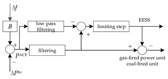
Figure 10.
High and low frequency signal allocation strategy.
The original ACE value is performed on low-pass filtering to obtain the low-frequency control component , and the calculation method is as follows:
where is the filter factor.
The ARR undertaken by the coal-fired unit and gas-fired power unit control group adopts the superposition of the PI control and CPS components in Equation (8). Thus the ACE low-frequency component is substituted into Equation (8) to calculate the total amount to-be-dispatched of the coal-fired unit and gas-fired power unit control groups, and then according to the respective proportion of their adjustable capacity and , their respective amounts to-be-dispatched is calculated as (taking the coal-fired unit and gas-fired power unit as the same control group):
where and are the amounts to-be- dispatched of the coal-fired unit and gas-fired power unit, respectively.
The ARR undertaken by the EESS control group is directly calculated by the proportional controller without considering the integral component and CPS component. Therefore, based on the high-frequency component signal of ACE, the total regulation amount undertaken by the EESS control group is:
4.3.3. Optimization of Dispatching Strategy among EESSs
When the SOC is within the physical and manual limits, the regulation range of EESSs is set as the intersection of the manual operation range of the SOC, the maximum discharging power and the maximum charging power. The switching between charging and discharging will be ignored when handling the operation range of EESSs in a way similar to thermal units. If the zero values of all EESSs are set as the midpoint of the operation range, the operation margin of the EESSs can be identical and the EESSs have an equal opportunity to participate in up- or down-regulation. If the regulation range is asymmetric, the power of the EESS will keep deviating from the zero point.
Therefore, the dispatching strategy for EESSs is designed with priority based on output power and the SOC. Similar to the pumped storage power station, the dispatching strategy for EESSs with two-way regulation capability can be realized by adjusting the current charging and discharging power or switching between the charging and discharging states. The dispatching strategy is described as follows:
- (1)
- When the power of EESSs is required to increase, the EESS is operated in the following order: charging, suspending and discharging regulation.
- (2)
- When the power of EESSs is required to decrease, the EESS is operated in the following order: discharging, suspending and charging regulation.
After considering the status switching of the EESS, the dispatching strategy undertaking ARR among EESSs is derived as follows. The EESSs are sorted according to the value of the SOC. When the power output is required to increase, the EESSs with larger SOCs increase the discharging power first. When the power output is required to decrease, the EESSs with smaller SOCs increase the charging power first. The status switching and the SOC are considered when determining the dispatched power among EESSs. The total power considering status switching and the SOC is smaller than the regulation step of the EESS.
5. Case Studies and Analysis of Simulation Results
In this section, a simulation model of test system is built on the Matlab/Simulink environment, and numerical simulation results of three cases of control modes are analyzed and compared to confirm the effectiveness and advantages of the proposed EESS control strategy.
5.1. Three Cases of EESS Control Modes
In order to compare different AGC control strategies, three cases of EESS control modes are proposed as follows.
- Case 1: The EESS only participates in peak load regulation and does not participate in power grid ACE regulation ().
- Case 2: The EESS does not participate in the peak load regulation ( equals to 0 or is determined by the floating baseline power calculation method proposed in Section 4.2.3), and only participates in power grid ACE regulation.
- Case 3: According to the proposed control strategy, the EESS participates in peak load regulation and power grid ACE regulation.
The simulation model of a typical two-area control system is adopted. The simulation data are derived from the actual AGC system of the Jiangsu power grid on a day in June 2021, and the time interval is 5 s. Five coal-fired units and five gas-fired power units are utilized as frequency regulation units with a total frequency regulation capacity of 1200 MW, which is a superposition with the AGC regulation range of ten units and accounts for about 1.5% of the maximum daily load. The actual ACE signal is reduced by 10% according to the proportion of total frequency regulation capacity, and the conventional frequency regulation units are removed one by one according to the frequency regulation capacity, from small to large. The reduced frequency regulation capacity of units is supplemented by the EESS to keep the total frequency regulation capacity of the system unchanged. The actual parameters of eight EESS stations in the Jiangsu power grid as shown in Table 4 are used as the simulation model parameters for the EESS.

Table 4.
Control parameters of grid-side EESSs in the Jiangsu power grid.
5.2. Comparative Analysis of Three Cases
The daily average CPS1 value of the simulation model is selected as the performance evaluation index of frequency regulation. The larger the CPS1 value, the better the performance evaluation of frequency regulation. The CPS1 values corresponding to different EESS capacity ratios under three cases are shown in Figure 10. Note that when the EESS capacity ratio is low (less than 30%), Case 2 has the best performance of frequency regulation, followed by Case 3, and Case 1 has the worst performance of frequency regulation. With the increase in EESS capacity ratio, when the EESS capacity ratio is higher than 30%, Case 3 has the best performance of frequency regulation, followed by Case 2 and Case 3, and Case 1 has the worst performance of frequency regulation. This shows that when the EESS capacity ratio is relatively high, the peak load regulation ability of the EESS cannot be ignored. By tracking the charging and discharging plan of the EESS, the advantages of frequency regulation of the EESS can be more effectively utilized and a better performance of frequency regulation can be achieved. The reason is that, although tracking the charge and discharge plans of the EESS cannot fully respond and quickly regulate the ACE in this control area, the frequency regulation has hysteric characteristics, which may not improve the current one minute average CPS1 value, but can improve the later one minute average CPS1 value.
From Figure 11, it can also be found that as the EESS capacity ratios to the frequency regulation capacity increase, the CPS1 value first increases and then decreases in these cases, which shows that the EESS capacity ratio to the frequency regulation capacity does not follow the rule “the bigger the better” due to the limited capacity of the EESS. With the increase in EESS capacity ratios, the frequency regulation task undertaken by the EESS becomes heavier, and it is more likely to have a low or high SOC, thereby reducing the capacity to provide frequency regulation and continue to provide frequency regulation services.
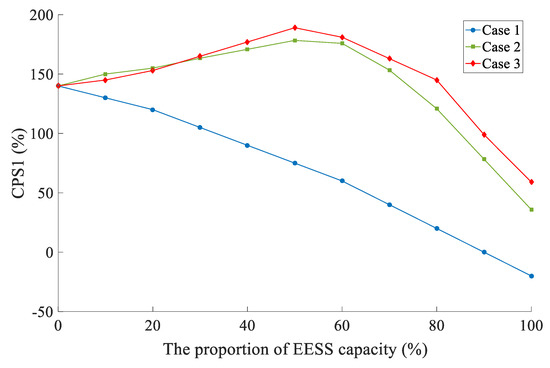
Figure 11.
CPS1 values corresponding to different EESS capacity ratios in three cases.
Figure 12 shows the availability rates of the EESS under different EESS capacity ratios. The availability rate of the EESS is the ratio of time when the SOC of the EESS is within the ideal upper and lower limits to the total time. For Case 2, the availability rate is high due to the adoption of the adaptive tracking of electricity quantity considering the SOC of EESSs; while for Case 1, since only ACE regulation is considered, the availability rate is relatively low. Although the baseline power will affect the frequency regulation performance of the system when the EESS is low (less than 30%), the baseline power calculation strategy of the EESS helps to cover the ideal upper and lower limits of the SOC of the EESSs and improve the availability rates of the EESSs.
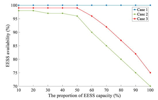
Figure 12.
Availability rates under different EESS capacity ratios.
5.3. Comparison and Analysis of Period Tracking of Electricity Quantity and Adaptive Tracking of Electricity Quantity
Four EESSs are selected to compare and analyze the effects of period tracking of electricity quantity in Section 4.2.2 and adaptive tracking of electricity quantity in Section 4.2.3. The SOC of EESSs using period tracking of electricity quantity is quite different, and the SOC trend tracking effect is not ideal, as shown in Figure 13. Figure 14 shows the SOC management effect of EESSs in the adaptive tracking of electricity quantity. The SOC curve of each EESS roughly meets the requirements of two charging and two discharging within a day. The SOC tracking trend of each EESS is consistent, and the SOC of each EESS is within a reasonable range to avoid the loss of deep charging and discharging of battery life.
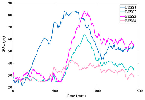
Figure 13.
SOC daily curve of EESSs under period tracking of electricity quantity.
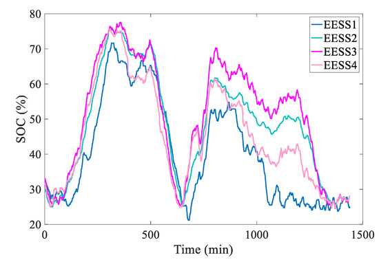
Figure 14.
SOC daily curve of EESSs under adaptive tracking of electricity quantity.
5.4. Comparative Analysis of Three ARR Allocation Strategies
Three ARR allocation strategies are proposed as follows.
- Case 4: The EESS control group, gas-fired power unit control group and coal-fired unit control group adopt a capacity proportional to allocation strategy;
- Case 5: The EESS control group, the gas-fired power unit control group and coal-fired control group adopt a fixed-priority (1: EESS control group, 2: gas-fired power unit, 3: coal-fired unit control group) allocation strategy;
- Case 6: The ARR adaptive allocation strategy, as proposed in this paper.
From the data in Table 5, it can be seen that after the implementation of the priority frequency regulation and adaptive allocation strategy, the frequency quality is significantly improved compared with the capacity ratio allocation strategy. The proportion of low-frequency difference components increases, and the proportion of high-frequency difference components decreases. Comparing the frequency difference distribution of case 5 and case 6, the results show that the frequency quality of the system has been further improved after adopting the proposed strategy in this paper. The proportion of frequency difference less than 0.03 Hz is further increased by 8%, and the proportion of frequency difference more than 0.05 Hz is further decreased by about 2%.

Table 5.
Frequency difference distribution of three cases under continuous disturbance conditions.
A further quantitative analysis is carried out on the regulation times, frequency regulation mileage and maximum power output of the EESS control group of these three cases, and the results are shown in Table 6.

Table 6.
Regulation data comparison of EESS control group.
It can be seen from the above table that the EESS control group has the most regulation times in case 6, because this case considers the SOC management control in the ARR dead band. In view of the good active management of the SOC, its availability is higher, thus the frequency regulation mileage is the highest. In case 5, although the EESS priority strategy is adopted, some EESSs in the EESS control group are likely to reach their charging and discharging limits and thus lose the ability to continue supporting, thus their frequency regulation mileage is the lowest.
In case 6, the frequency regulation signal and SOC variation in the EESS are shown in Figure 15. EESSs participate in most of the ACE regulation and control, and at the same time are constrained by their capacities; the maximum regulation range of the EESS is [−100, 100]. It can be seen from the SOC variation that the SOC of the EESS is basically maintained at around 50% on the load plateau stage. On the load ramping stage, the ACE change speed and amplitude both increase; thus, the SOC deviates from the ideal operating range. However, due to the large EESS capacity and SOC constraint management, the EESS can ensure continuous frequency regulation support during the frequency regulation process.
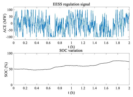
Figure 15.
Frequency regulation signal and SOC variation in EESS.
6. Case Studies and Analysis on the Effectiveness of EESS Participating in AGC of the Jiangsu Power Grid
6.1. Operation Analysis of EESSs Participating in AGC of the Jiangsu Power Grid under the Peak Shaving Control
After October 2018, according to the variation in generation and load of the Jiangsu power grid, Zhenjiang EESSs participated in ACE control, such as allowing conventional units to take full advantage of their regulation performance. Between 1 October and 16 November 2018, the EESSs operated under the SCHER mode in which the scheduled value determined by the “charging and discharging twice per day” strategy was set as the baseline power for participation in ACE regulation. The control parameters of eight EESSs in the Jiangsu power grid for participation in AGC are shown in Table 4.
The EESSs were controlled by the SCHER mode. As shown in Figure 16, the EESSs participated in ACE regulation while operating in accordance with the scheduled charging and discharging curves.
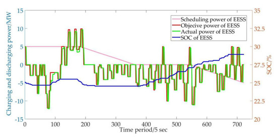
Figure 16.
Operation curves of Danyang EESS at 9:00 on 2 October.
Moreover, the SOC was considered in EESS operation due to the constraint of capacity and the limited number of deep charging and discharging times. When the real-time SOC is lower than the preset threshold, discharging is prohibited and the power command is no greater than 0, as shown in Figure 17. When the real-time SOC is higher than the preset threshold, charging is prohibited and the power command is no smaller than 0.
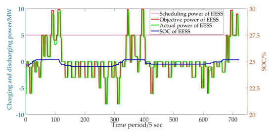
Figure 17.
Operation curves of Danyang EESS with prohibited discharging.
6.1.1. Comparative Analysis of AGC Regulation Performance
As shown in Figure 18, with the participation of EESSs in AGC, the mean value of the ACE decreased and the fluctuations were mitigated. Table 7 shows the statistics of the units’ regulation performances on a selected holiday, the National Day of China. It can be found that the EESSs are capable of mitigating the power imbalance at the time scale of the second, thus the deteriorating ACE can be arrested and the stress on conventional units for frequency regulation is alleviated, which is favorable to enhance the dynamic regulation performance of the system.
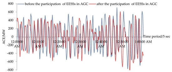
Figure 18.
ACE curves before and after the participation of EESSs in AGC.

Table 7.
Statistics of units’ regulation performance.
6.1.2. Comparative Analysis of the CPS Index
Before the participation of EESSs in AGC for coordinated ACE regulation, the CPS1 indices of the Jiangsu power grid in 2017 and from January to September in 2018 are 137.1 and 136.9, respectively, and there is no significant difference. The Zhenjiang grid-side EESSs were in operation at 16:00 on 30 September 2018 in the SCHER mode. After the implementation of EESSs, the CPS1 index of the Jiangsu power grid was considerably increased.
During the 2018 National Day holiday, the maximum electric load of the Jiangsu power grid was about 54 GW, and the up and down spinning reserve capacity was about 5 GW, which are all similar to those from the 2017 and 2016 National Day holidays. As shown in Figure 19, the average CPS1 of the Jiangsu power grid during the 2018 National Day holiday was 167.6, which was 16% higher than the corresponding value in the past (the average CPS1 during the 2015–2017 National Day holidays were 147.3, 148.9 and 145.0, respectively).
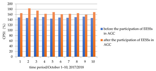
Figure 19.
CPS1 of The Jiangsu power grid during the National Day holiday in 2017 and 2018.
6.2. Analysis on the Effectiveness of AGC with Adaptive Baseline Power Considering SOC
6.2.1. Effectiveness of Adaptive Tracking of Electricity Quantity considering SOC of EESSs
Eight EESSs are implemented in the BASER mode for the adaptive tracking of electricity quantity; the parameters of the EESSs are shown in Table 2. As shown in Figure 20, the SOC curves generally meet the “charging and discharging twice” demand and the SOC is controlled within 20–80%, thus the deterioration of the battery lifespan is prevented and the efficiency of the EESS is improved. The difference in SOC among EESSs can be mitigated by apt arrangement of the electricity, which is favorable to reasonably dispatching EESSs resources.
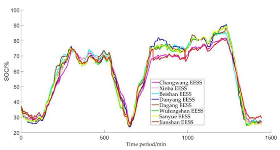
Figure 20.
SOC curves of EESSs under adaptive tracking of electricity quantity on 3 October 2020.
Figure 21 shows the operating curve of a 15 MW/30 MWh EESS. It can be observed that the power output of EESS varies frequently to participate in AGC and covers the maximum available charging and discharging powers. These results indicate that the baseline power of the EESS can effectively guide the SOC so that the production of required electricity is guaranteed.
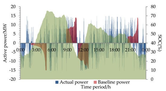
Figure 21.
Operation curves of an EESS under adaptive tracking of electricity quantity.
6.2.2. Comparative Analysis of the CPS Index
As shown in Table 8, the EESSs were alternately operated in the BASER mode and the BASEO mode in order to verify the regulation performance of the EESS control modes. The baseline power calculation methods of the two modes are identical. The BASEO mode was implemented only when participating in peak regulation and was disabled when participating in ACE regulation.

Table 8.
AGC control mode of EESSs in August and September 2020.
During the test periods, the maximum load of the Jiangsu power grid was about 90–100 GW in August and 80–90 GW in September, respectively, and the up and down spinning reserve capacity was set as 6–10 GW. In August and September 2020, the Jiangsu power grid contained coal-fired units (75.5 GW), gas-fired power units (15 GW), nuclear power units (4.3 GW) and renewable energy units (20 GW). During the test periods, the electricity generation and the demand condition within a week were similar.
The CPS1 index of the Jiangsu power grid during the tests conducted in August and September 2020 are shown in Table 9 and Table 10, respectively. As shown in Figure 22, between August 2 and 5, the EESSs were in the WAIT mode and withdrawn from system AGC; from 29 August to 1 September and from 9 to 12 September, the EESSs were in the BASEO mode, only participated in peak regulation and did not participate in ACE regulation. It can be observed that on the day when the load was similar to the regulation reserve, the CPS1 when the EESSs were in the BASEO mode was much smaller than that when the EESSs were in the BASER mode.

Table 9.
CPS1 of the Jiangsu power grid in August 2020.

Table 10.
CPS1 of the Jiangsu power grid in September 2020.
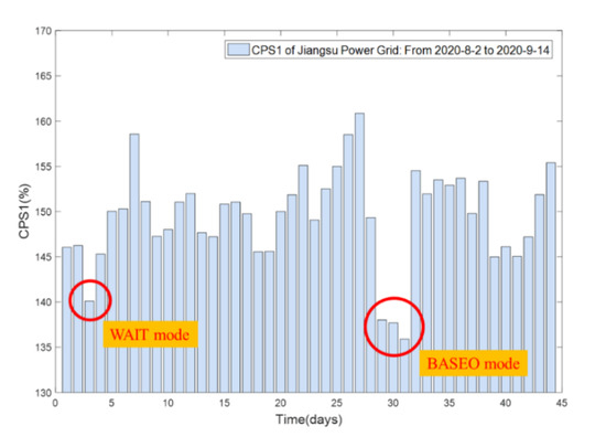
Figure 22.
CPS1 of the Jiangsu power grid in August and September 2020 (exceptional data excluded).
6.2.3. Quantitative Analysis of the Regulation Performance of EESSs
According to the comparative analysis of the regulation rate and precision of EESSs, gas-fired power units and coal-fired units, the participation of the EESS in AGC is swift, precise and stable. Then, the quantitative analysis of the EESS regulation performance is conducted to verify the contribution of EESSs to CPS1.
The EESSs were operated in the BASER mode when participating in AGC and the command interval was twenty seconds. Because the command intervals of gas-fired power and coal-fired units are zero seconds, the ARR is averagely dispatched among the EESSs, gas-fired powers and coal-fired units over each AGC control cycle (once every five seconds). Table 11 shows the daily dispatch of ARR every AGC control cycle from 5 September to 14 September.

Table 11.
Comparison of ARR dispatched among the EESSs, gas-fired power and coal-fired units (Unit: MW).
Table 12 shows a regulation performance comparison of EESSs in BASER mode and BASEO mode. In BASER mode, the actual dispatched ARR of EESSs is 6.6 MW, accounting for 2.68% of the total ARR (246 MW). The dispatched amount of gas-fired power and coal-fired units each cycle was about 78 MW, the amount to be regulated in the same direction of unready units was 154 MW, and the total actual dispatched amount was 232 MW. The EESSs could make a full response to the dispatched regulation amount within a single control cycle. However, according to the regulation step of the gas-fired power and coal-fired units, the regulation demand for these units lasted one minute. Thus, the 78 MW dispatched amount could be fully addressed by these units after one minute and the actual contribution of these units in every control cycle was 6.5 MW, which was similar to that of the EESSs. The rest regulation amount was used as the amount-to-be-regulated in the same direction as the unready units in the following control cycles. Because changing the ARR direction (about every twenty seconds) would restrain the units with the regulation in the opposite direction, the actual contribution of the amount to be regulated in the same direction of unready units every control cycle was 19.5 MW, which was equivalent to the contribution of three EESSs. The 32.6 MW contribution of total regulation amount of the system accounted for about 13.3% of the total ARR.

Table 12.
Regulation Performance Comparison of EESSs in BASER mode and BASEO mode (Unit: MW).
In BASEO mode, the dispatched amounts of gas-fired power and coal-fired units each control cycle were about 82 MW, the amount to be regulated in the same direction of unready units was 167.5 MW, and the total actual dispatched amount was 249.5 MW. According to the regulation step of the gas-fired power and coal-fired units, the regulation demand for these units lasted one minute. Thus, the 82 MW dispatched amount could be fully addressed by these units after one minute and the actual contribution of these units every control cycle was 6.83 MW. The rest regulation amount was used as the amount to be regulated in the same direction of unready units in the following control cycles. Because changing the ARR direction (about every twenty seconds) would restrain the units with the regulation in the opposite direction, the actual contribution of the amount to be regulated in the same direction of unready units every control cycle was 20.5 MW. The 27.3 MW contribution of total regulation amount of the system accounted for about 10.6% of the total ARR, which was about 259 MW.
It can be observed that the contribution of total regulation amount of the units when the EESSs were operated in BASER mode (13.3%) was 2.7% higher than that when the EESSs were operated in BASEO mode (10.6%), which was similar to the contribution of EESSs under BASER mode (2.68%). In BASER mode, the 26 MW contribution of total regulation amount of the gas-fired power and coal-fired units accounted for about 10.6% of the total ARR 246 MW. In BASEO mode, the 27.3 MW contribution of the total regulation amount of the gas-fired power and coal-fired units accounted for about 10.6% of the total ARR 258 MW. These results indicate that although the contribution of gas-fired power and coal-fired units increased when the EESSs were operated in BASEO mode, the contribution rate of the total regulation amount of these units remained almost unchanged.
Moreover, the CPS1 when the EESSs were operated in BASER mode was 152.3, which was 3.37% higher than that when the EESSs were operated in BASEO mode (145.6). The contribution of the total regulation amount of the system when the EESSs were operated in BASER mode was 2.7% higher than that when the EESSs were operated in BASEO mode. These results validate the effectiveness of the statistical analysis on the regulation performance of EESSs.
It should be noted that although the contribution of the gas-fired power and the coal-fired units was four times that of the EESSs, it did not mean that the regulation of the gas-fired power and the coal-fired units could be replaced by EESSs with the capacity four times the current volume. The number of brake commands of the gas-fired power and coal-fired units was reduced by about 30%. The EESS mainly handled the ARR reciprocating around zero because of its flexibility and rapidity while the ARR stayed positive or negative, as the constantly changing ramp load was mainly handled by the gas-fired power and the coal-fired units rather than the EESSs with limited capacity.
Figure 23 shows the SOC daily average curves of EESSs operating in BASEO and BASER modes, respectively. It can be observed that the SOC change trends of EESSs operating in BASEO and BASER modes are similar during the time periods 2:00–5:00, 08:45–10:45, 11:00–13:00 and 20:30–22:30, which demonstrates that the two modes have similar peak-load shifting performances.
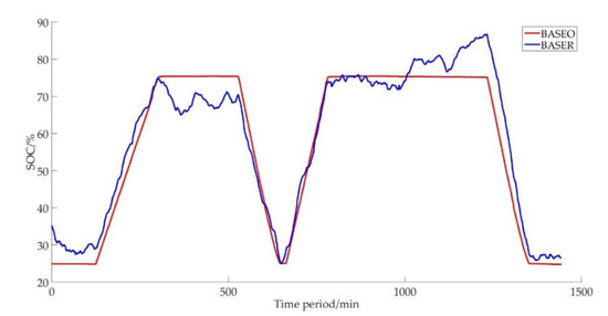
Figure 23.
SOC daily average curves of EESSs operating in BASEO and BASER modes.
6.3. Cost-Benefit Analysis of EESS Participating in AGC
The frequency control ancillary service market has started commissioning operations in the Jiangsu power grid since 2020. EESSs with charging/discharging powers above 5 MW/10 MWh can register as market members to provide frequency control ancillary service. The compensation fee of the frequency control auxiliary service market can be divided into basic compensation and dispatched compensation. The basic compensation fee of EESS i is calculated based on the frequency regulation performance , frequency regulation capacity , operation rate , and the compensation standard (2 RMB/MW).
The dispatched compensation fee of EESS i is calculated is based on frequency regulation mileage , frequency regulation performance and clearing price in the frequency control ancillary service market.
The clearing price of EESS i is calculated according to the formula . is the highest clearing price of thermal units in the market and the compensation standard of EESS meets . The lower limit and upper limit of the clearing price are 0.1 RMB/MW and 1.2 RMB/MW, respectively.
The average daily compensation fee of EESSs in BASER mode is shown in Table 13. At this stage though, the capital cost of EESS is still high. Considering the investment and operation cost of EESS per kW is RMB 4600, it can at least take two years to recover the capital cost.

Table 13.
The average daily compensation fee of EESSs in BASER mode (Unit: x104 RMB).
7. Conclusions
EESSs have many advantages, such as short construction periods, fast response speeds and various application modes. In recent years, they have been continuously expanded in scale and have been more and more widely used with the encouragement of the national and local governments. This case study of the Jiangsu power grid that integrated eight EESSs with a total capacity of 101 MW/202 MWh was performed to confirm the effectiveness and advantages of the proposed operation and control strategy of the EESS. The conclusions of this study are summarized as follows:
- (1)
- The proposed control strategies of the EESS can simultaneously coordinate different time-scale application requirements, such as peak-load shifting and LFC. Furthermore, all proposed control modes of the EESS can take into account the frequency regulation requirements. The adaptive tracking of electricity quantity considering the SOC of EESSs is proposed to improve the efficiency of EESSs and slow down the processes of battery degradation.
- (2)
- The control group of EESSs is designed and added to participate in ACE regulation of the Jiangsu control area together with the control groups of coal-fired units and gas-fired power units. Furthermore, in order to coordinate the fast and slow regulation sources, this paper proposed the frequency regulation strategy of multiple resources considering EESSs, including the control group dispatching principle, and the regulating volume transfer and balance method. By prioritizing the use of EESSs with excellent performances to participate in power grid frequency regulation, the number of brake commands of the gas-fired power and coal-fired units has been reduced by about 30%. The EESS mainly handled the ARR reciprocating around zero because of its flexibility and rapidity while the ARR that stayed positive or negative for constantly changing ramp load was mainly handled by the gas-fired power and the coal-fired units rather than the EESSs with limited capacity.
- (3)
- The results show that the CPS1 of the Jiangsu power grid is significantly enhanced after the participation of EESSs in ACE regulation. Quantitative analyses conducted on the operation data collected from 5 to 14 September 2020 validate that by implementing the AGC strategy with adaptive baseline power considering the SOC of energy storage, the CPS1 can be increased by around 3% with the EESSs operating in BASER mode.
- (4)
- Moreover, the control strategy yields net profit for the EESS owners, and the investment of the EESS participating in the frequency control ancillary service market of the Jiangsu power grid can be paid back in about two years.
The proposed control strategy of EESSs participating in bulk power systems frequency regulation should be worthy of further promotion and used for practical applications in different countries and regions.
Author Contributions
Formal analysis, J.F.; Project administration, J.F.; Resources, Z.L.; Software, Z.L.; Writing—original draft, J.F.; Writing—review & editing, Y.W. and Q.X. All authors have read and agreed to the published version of the manuscript.
Funding
This research is supported by the Science and Technology Project of State Grid Jiangsu Electric Power Co., Ltd. (5419-201918206A-0-0-00).
Institutional Review Board Statement
Not applicable.
Informed Consent Statement
Not applicable.
Data Availability Statement
Not applicable.
Conflicts of Interest
The authors declare no conflict of interest.
References
- Hu, J.; Bhowmick, P. A consensus-based robust secondary voltage and frequency control scheme for islanded microgrids. Int. J. Electr. Power Energy Syst. 2020, 116, 105575. [Google Scholar] [CrossRef]
- Wu, W.; Lin, B. Application value of energy storage in power grid: A special case of China electricity market. Energy 2018, 165, 1191–1199. [Google Scholar] [CrossRef]
- Hau, L.C.; Lim, Y.S.; San, L.S.M. A novel spontaneous self-adjusting controller of energy storage system for maximum demand reductions under penetration of photovoltaic system. Appl. Energy 2020, 260, 114294. [Google Scholar] [CrossRef]
- Oshnoei, A.; Kheradmandi, M.; Muyeen, S.M. Robust control scheme for distributed battery energy storage systems in load frequency control. IEEE Trans. Power Syst. 2020, 35, 4781–4791. [Google Scholar] [CrossRef]
- Wang, Y.; Xu, Y.; Tang, Y.; Liao, K.; Syed, M.H.; Guillo-Sansano, E.; Burt, G.M. Aggregated Energy Storage for Power System Frequency Control: A Finite-Time Consensus Approach. IEEE Trans. Smart Grid. 2019, 10, 3675–3686. [Google Scholar] [CrossRef] [Green Version]
- Kroposki, B.; Johnson, B.; Zhang, Y.; Gevorgian, V.; Denholm, P.; Hodge, B.-M.; Hannegan, B. Achieving a 100% Renewable Grid: Operating Electric Power Systems with Extremely High Levels of Variable Renewable Energy. IEEE Power Energy Mag. 2017, 15, 61–73. [Google Scholar] [CrossRef]
- Horesh, N.; Quinn, C.; Wang, H.; Zane, R.; Ferry, M.; Tong, S.; Quinn, J.C. Driving to the future of energy storage: Techno-economic analysis of a novel method to recondition second life electric vehicle batteries. Appl. Energy 2021, 295, 117007. [Google Scholar] [CrossRef]
- Pareis, E.; Hittinger, E.; Belikov, J. Emissions Effects of Energy Storage for Frequency Regulation: Comparing Battery and Flywheel Storage to Natural Gas. Energies 2021, 14, 549. [Google Scholar] [CrossRef]
- Zhong, J.; He, L.; Li, C.; Cao, Y.; Wang, J.; Fang, B.; Zeng, L.; Xiao, G. Coordinated control for large-scale EV charging facilities and energy storage devices participating in frequency regulation. Appl. Energy 2014, 123, 253–262. [Google Scholar] [CrossRef]
- Cheng, Y.; Tabrizi, M.; Sahni, M.; Povedano, A.; Nichols, D. Dynamic available AGC based approach for enhancing utility scale energy storage performance. IEEE Trans. Smart Grid. 2014, 5, 1070–1078. [Google Scholar] [CrossRef]
- Liu, Y.; Du, W.; Xiao, L.; Wang, H.; Bu, S.; Cao, J. Sizing a hybrid energy storage system for maintaining power balance of an isolated system with high penetration of wind generation. IEEE Trans. Power Syst. 2016, 31, 3267–3275. [Google Scholar] [CrossRef]
- Guzman, E.N.S.; Arriaga, M.; Canizares, C.A.; Simpson-Porco, J.W.; Sohm, D.; Bhattacharya, K. Regulation signal design and fast frequency control with energy storage systems. IEEE Trans. Power Syst. 2021, 37, 224–236. [Google Scholar] [CrossRef]
- Xinran, L.; Tao, D.; Jiyuan, H.; Shujuan, L.; Jun, Y.; Min, D. Battery Energy Storage Systems Self-adaptation Control Strategy in Fast Frequency Regulation. High Volt. Eng. 2017, 43, 2362–2369. (In Chinese) [Google Scholar]
- Hu, Z.; Xie, X.; Zhang, F.; Zhang, J.; Song, Y. Research on Automatic Generation Control Strategy Incorporating Energy Storage Resources. Proc. CSEE 2015, 34, 5080–5087. (In Chinese) [Google Scholar]
- Zhang, C. Optimization Planning and Operation Technology of Large-Scale Energy Storage System; China Electric Power Press: Beijing, China, 2022; pp. 137–184. [Google Scholar]
- Lee, S.-J.; Kim, J.-H.; Kim, C.-H.; Kim, S.-K.; Kim, E.-S.; Kim, D.-U.; Mehmood, K.K.; Khan, S.U. Coordinated control algorithm for distributed battery energy storage systems for mitigating voltage and frequency deviations. IEEE Trans. Smart Grid 2015, 7, 1713–1722. [Google Scholar] [CrossRef]
- Dong, N.; Han, X.; Gao, Z.; Chen, Z.; Wu, A. SPSA-based data driven control strategy for load frequency control of power systems. IET Gener. Transm. Distrib 2018, 12, 414–422. [Google Scholar] [CrossRef]
- Wang, Y.; Wan, C.; Zhou, Z.; Zhang, K.; Botterud, A. Improving Deployment Availability of Energy Storage with Data-Driven AGC Signal Models. IEEE Trans. Power Syst 2018, 33, 4207–4217. [Google Scholar] [CrossRef]
- Kofinas, P.; Dounis, A.; Vouros, G. Fuzzy Q-Learning for multi-agent decentralized energy management in microgrids. Appl. Energy 2018, 219, 53–67. [Google Scholar] [CrossRef]
- Yan, Z.; Xu, Y.; Wang, Y.; Feng, X. Deep reinforcement learning-based optimal data-driven control of battery energy storage for power system frequency support. IET Gener. Transm. Distrib. 2020, 14, 6071–6078. [Google Scholar] [CrossRef]
- Yao, M.; Shoults, R.R.; Kelm, R. AGC logic based on NERC’s new control performance standard and disturbance control standard. IEEE Trans. Power Syst. 2000, 15, 852–857. [Google Scholar] [CrossRef]
- Wang, Z.; Wang, Y.; Ding, Q.; Wang, C.; Zhang, K. Energy storage economic analysis of multi-application scenarios in an electricity market: A case study of China. Sustainability 2020, 12, 8703. [Google Scholar] [CrossRef]
- Gao, Z.H.; Teng, X.L.; Zhang, X.B. Automatic generation control strategy under control performance standard for interconnected power grids. Autom. Electr. Power Syst. 2005, 29, 40–44. (In Chinese) [Google Scholar]
- Frequency Control Ancillary Service Market of Jiangsu Power Grid. 2020. Available online: http://jsb.nea.gov.cn/news/2020-7/202073154200.html (accessed on 5 June 2022). (In Chinese)
Publisher’s Note: MDPI stays neutral with regard to jurisdictional claims in published maps and institutional affiliations. |
© 2022 by the authors. Licensee MDPI, Basel, Switzerland. This article is an open access article distributed under the terms and conditions of the Creative Commons Attribution (CC BY) license (https://creativecommons.org/licenses/by/4.0/).