Article

An Efficient Fault Detection Method for Induction Motors Using Thermal Imaging and Machine Vision

1
Department of Electrical, Electronics and Telecommunication Engineering, University of Engineering and Technology, Faisalabad Campus, Lahore 38000, Pakistan
2
School of Electrical Engineering, Southeast University, Xuanwu District, Nanjing 210096, China
3
Department of Energy Systems Engineering, University of Agriculture, Faisalabad 38000, Pakistan
4
Department of Electrical Engineering & Technology, Riphah International University, Faisalabad 38000, Pakistan
5
Department of Mechatronics and Control Engineering, University of Engineering and Technology, Faisalabad Campus, Lahore 38000, Pakistan
6
Department of Electrical Engineering, The Islamia University of Bahawalpur, Bahawalpur 63100, Pakistan
*
Authors to whom correspondence should be addressed.
Sustainability 2022, 14(15), 9060; https://doi.org/10.3390/su14159060
Submission received: 1 July 2022 / Revised: 15 July 2022 / Accepted: 21 July 2022 / Published: 24 July 2022

Abstract

:
Induction motors (IMs) are the backbone of industry, and play a vital role in daily life as well. However, induction motors face various faults during their operation, which may cause overheating, energy losses, and failure in the motors. Keeping in mind the severity of the issues associated with fault occurrence, this paper proposes a novel method of fault detection in induction motors by using “Machine Vision (MV)” along with “Infrared Thermography (IRT)”. It is worth mentioning that the timely prevention of faults in the IM ensures the motor’s safety from failures, and provides longer service life. In this work, a dataset of thermal images of an induction motor under different conditions (i.e., normal operation, overloaded, and fault) was developed using an infrared camera without disturbing the working condition of the motor. Then, the extracted thermal images were effectively used for the feature extraction and training by local octa pattern (LOP) and support-vector machine (SVM) classifiers, respectively. In order to enhance the quality of feature extraction from images, the LOP was implemented along with a genetic algorithm (GA). Finally, the proposed methodology was implemented and validated by detecting the faults introduced in an induction motor in real time. In addition to that, a comparative study of the suggested methodology with existing methods also verified the supremacy and effectiveness of the proposed method in comparison to the previous techniques.

1. Introduction

Induction motors are known as industrial workhorses in the present era, as they are the most popular rotating machines being used in industry [1]. Induction motors play a pivotal role in many industrial applications, such as the oil and gas industry, manufacturing plants, refining and milling plants, and many more. The usage of induction motors in various industrial applications also demands the smooth and fault-free operation of the motors under the harsh conditions of the industrial environment. Fault occurrence in the motors may lead to reduction in output, loss of revenue, and energy losses, ultimately posing a great challenge in terms of smooth industrial operations. Moreover, it should be noted that the continuous usage of faulty equipment (such as induction motors) within the system can severely affect the performance of other electrically connected equipment. Therefore, timely fault diagnosis in electrical motors and other electronic equipment is of utmost importance for safety, long life, and high efficiency. According to a previous study [2], the effective implementation of fault prediction in industry for electronic equipment can reduce the cost of operations by 33–50%, which was neglected by most production and generation centers for a long time. It was found that predictive maintenance has several advantages, such as reduction in unscheduled system shutdowns, diminution of the required manpower for maintenance, and improvement of the equipment’s service life. Overall, it can be deduced from the above that timely fault diagnosis and condition monitoring play an important role in the smooth and steady operation of induction motors and industrial operations.
Theoretically, IMs can experience different types of faults, including both electrical and mechanical faults [3]. The electrical faults can be further divided into stator and rotor faults. The stator faults include short-circuiting in the stator winding, damage to the core, core losses (e.g., hysteresis and eddy current losses), or defects in the frame of the stator [4]. Meanwhile, the rotor faults include short-circuiting in the rotor winding, eccentricity in the rotor, and copper losses [3,5,6]. On the other hand, the mechanical faults include damage to the bearings and to the shaft of the motor [7]. However, it is worth noting that in the induction motors, approximately 36% of the faults are due to stator winding faults [4], because the stator parts undergo extreme stress (whether electrical or mechanical stress). Usually, the electrical faults in the stator winding are phase-to-phase faults, phase-to-ground faults, and inter-turn faults [8,9,10]. Furthermore, as time passes, the IM performance also deteriorates due to corrosion, faults in wiring, overloading, unbalanced loading, and usage of poor materials in construction [11], which also enhance the chances of fault occurrence.
In addition to the aforementioned problems, the faults also cause a rise in the temperature of the IM beyond the allowable temperature limit of the motors, ultimately affecting the service life of the IM drastically and reducing its service life by half for every 10 °C rise in temperature. Fortunately, this temperature rise due to faults plays a crucial role in the fault detection, because the increase in the thermal energy due to faults can be effectively detected in real time by the thermal imaging of the machine. Normally, all electrical equipment with a temperature above 0 °C emits infrared (IR) radiation, because the current passing through the equipment causes an increase in the heat signature of the equipment. However, the naked human eye cannot detect the heat signature of the object, due to the fact that the heat waves from the heated objects are in the infrared range. Therefore, IRT can be used to capture the heat signature of the heated objects in order to visualize the heat energy distribution of the objects. In recent years, IRT has become an important tool for detecting hot spots and defects in the electrical equipment due to its simplicity and effectiveness. Several previous studies have shown that IRT has a variety of applications and can be a useful technique for fault detection by capturing the heat signature of the electrical equipment under operation [12,13,14,15,16,17,18,19,20,21]. Thus, thermography can identify fault occurrence in real time, and can protect the equipment and system from various problems occurring due to faults. Currently, run-to-failure (RTF) maintenance is the most widely used method for the life extension and protection against faults of IMs in industry. Meanwhile, in infrared thermography (IRT), the detection of thermal defects of the object is achieved by the inspection of its temperature change (∆T), and this procedure is called qualitative-based estimation of temperature [22,23,24]. Thus, IRT enables the timely detection of the faults in the equipment, and is more efficient compared to RTF.
Previously, various artificial intelligence (AI) techniques—such as fuzzy logic [25] and artificial neural networks (ANNs)—have been implemented along with IRT for fault detection in motors, due to their ability to execute complex tasks without significant cost outlays. Artificial intelligence has numerous applications in industry [26,27,28], power systems, and medicine. For example, a few works [24,29] have reported the inclusion of artificial neural network (ANN) techniques along with IRT in order to classify the defects in different materials, because the ANN is a known strong and powerful mathematical model for pattern recognition models. In these works, the different thermal images from the machine were taken as inputs for ANNs to classify the faults in the electrical hardware. In another work [30], the neuro-fuzzy approach was explored to detect the faults in the machines, while the inputs to this system were thermal images of the machine. However, in the abovementioned works [24,29,30], system performance of more than 10% could not be obtained, making them unsuitable for effective fault detection in the objects. Despite the availability of these AI-based fault-diagnosis techniques, there is still a chance of failure in the induction motor due to their low effectiveness, cost factor, and increased time requirements for data collection and analysis.
Therefore, in view of the above constraints, machine learning can be a suitable choice for the fault detection of industrial loads, if used along IRT. It has been reported in some recent works that machine learning can handle the challenge of fault detection efficiently [31,32,33]. Machine vision for fault detection mainly consists of feature extraction and training classifiers. There are multiple options for feature extractors and classifiers for the implementation of machine learning. For instance, in [34], the author obtained 93.38% of the accurate data for a three-layer ANN classifier, and the RBG color scheme was explored for scaling and to identify the internal temperature of the machine. Furthermore, additional reports on the support-vector machine (SVM) and the genetic structure of ANN multilayer perception (MLP) in recent works [35,36] on the fault diagnosis of electrical equipment showed accuracy levels of 83% and 79.78%, respectively. The total dataset for SVM was 20 pictures with a feature sample of Zernike moments, while the MLP was able to show further improvement in results with fewer figures. For the purpose of feature extraction in machine vision techniques, the local octa patterns (LOPs) can also be used, due to their special property of “four derivative directions”. The LOP technique can be a suitable candidate for the fault detection in industrial loads if used along with the IRT, due to its excellent feature-extraction ability. It is essentially a feature-extraction algorithm, and is an extension of the local tetra pattern (LTP) [37] algorithm. It processes an image by considering the diagonal, vertical, and horizontal derivative directions of the image pixels to represent a region (four derivative directions), whereas the previously reported methods—such as “LTP”—take into account only the horizontal and vertical directions (two directions) [38]. Thus, it may be concluded from the above that the inclusion of the diagonal direction in LOP makes the feature more descriptive, and the more descriptive the feature, the better the retrieval result. As the retrieval result gets better, the detection accuracy of the algorithm in the fault detection cases also increases. Finally, it can be concluded from the whole discussion that IRT can be effectively used along with machine vision techniques for the predictive maintenance of equipment without complete shutdown of industry, and using this technique can reduce manpower and several other wastes of resources.
In this paper, the IRT method was used along with machine vision for the timely diagnosis of IM faults in order to ensure safe and smooth operation of the IM. A dataset of thermal images of IM was generated under normal, overload, and fault conditions, and then this dataset was trained using machine vision for the diagnosis of faults. There are three stages in the proposed diagnostic method—(i) data acquisition, (ii) feature extraction and training, and (iii) fault identification—but among these stages the feature extraction and training is the most important stage. In this work, the LOP method was used along with GA for the feature extraction, because this provides better image description, as mentioned above. For the data training, the SVM classifier trains the data based on samples as received from the LOP. Finally, the methodology was validated in real time by introducing and detecting faults in an IM. The system effectively recognizes different fault patterns of the induction motor, and informs the user about fault occurrence after identification. Overall, this work presents a novel technique for fault diagnosis in IMs by using IRT and machine vision simultaneously, and provides a decent precision rate for the diagnosis of faults.

2. Experimental Setup

The experimental setup of the suggested method can be divided into three stages of data acquisition, feature extraction, and training. The detailed explained for each section is provided below.

2.1. Data Acquisition

The very first step in this method is to capture the thermal images (data acquisition stage) of the IM under various (normal, overload, and faulty) conditions to generate the database of thermal images. For this purpose, a digital infrared camera was used to capture the thermograms of the IM by keeping the camera in line with the IM at 1–2 feet distance. The complete specifications of the three-phase IM (equipped with a variable-frequency drive) used in this experiment are provided in Table 1. The corresponding experimental setup (with different view angles) for capturing the thermal images of the IM is provided in Figure 1. The bottom-right image provides a closer view of the IR camera interfaced with a mobile phone for capture purposes. The IR camera was kept at a certain distance from the IM (connected with three-phase supply), and the images were captured of the IM under various conditions. In order to develop the database of thermograms, the thermal images of the IM were captured for each condition, i.e., normal, overload, and fault. The sample thermal images defining the different heat signatures of the IM under the three mentioned conditions can be seen in Figure 2. In this work, the state of the motor is divided into three different levels based on the temperature variation (ΔT), as shown in Table 2. The variable ΔT is the temperature difference between the ambient temperature and the hotspot temperature of the IM. Moreover, the recommended outputs in this proposed work are also dependent on the parameter ΔT. It is evident from the table that no action is required under normal operating conditions, while under overload conditions it is necessary to wait for some time, and the system should be shut down completely under fault conditions. It should be noted that the overloaded condition can severely damage the motor if it persists for longer periods; therefore, the wait time for the overload condition should be chosen accordingly.
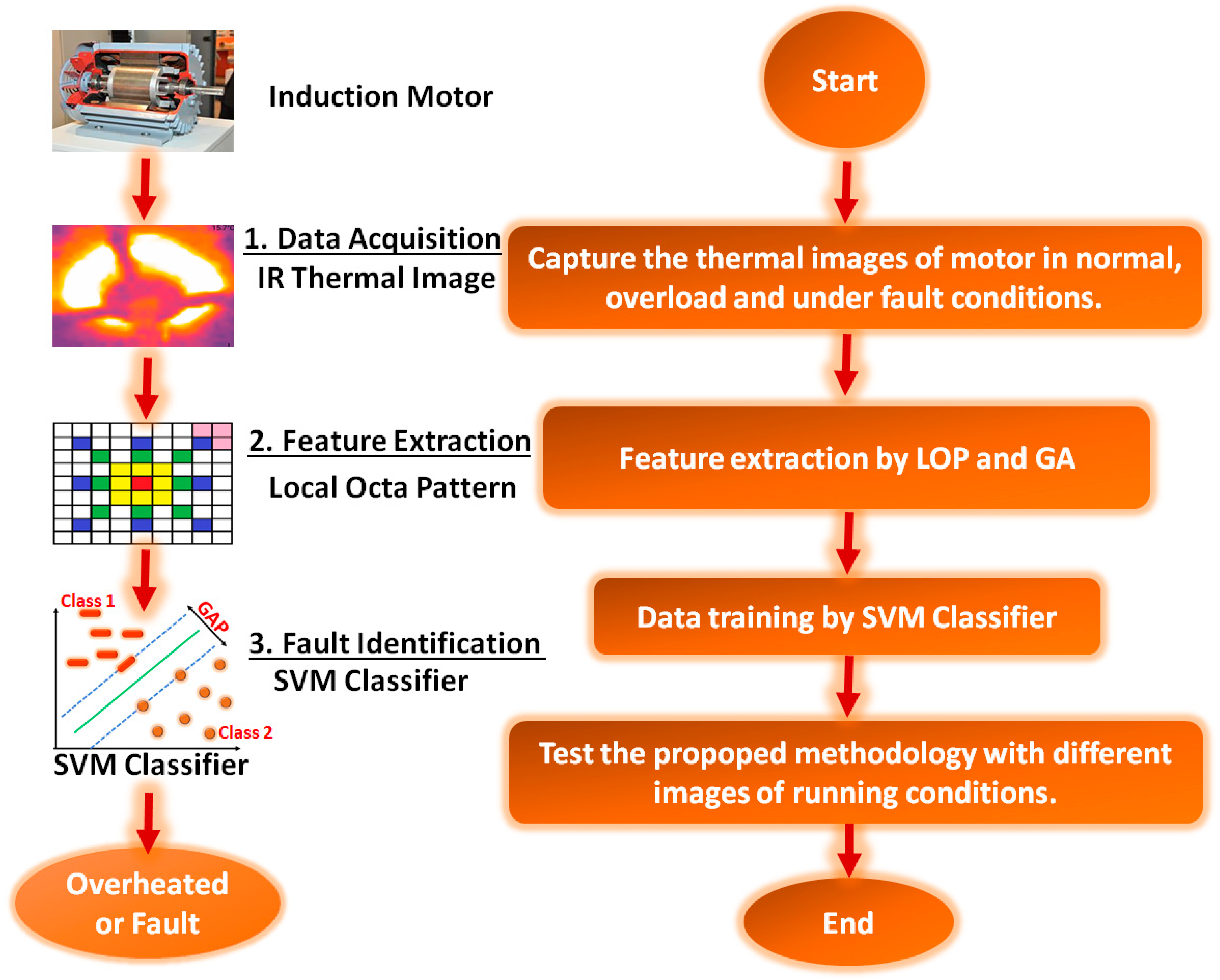
The complete flowchart of the fault detection is shown in Figure 3. Figure 3 shows that after the initial data acquisition, the next stage is “feature extraction” of thermal images, and this stage plays a key role in the development of the fault detection and diagnosis method [37,39,40]. The hundreds of thermal images (dataset) captured in the first stage are used as the input for the feature-extraction stage. After the initial processing of these sample images, features are extracted from the images using the LOP technique. In the next stage, the data are forwarded to the SVM classifier for the training of the data. After the completion of the training cycle, the proposed method can be used effectively and accurately for fault detection of the IM by taking the IR thermal images of the IM as inputs and correlating them with the trained data.

2.2. Feature Extraction through LOP

The data obtained through IRT are forwarded to the feature extractor in order to perform feature extraction on the dataset of thermal images. The mechanism follows Equations (1)–(18) in order to perform feature extraction on an image using local octa patterns. For the feature extraction of thermal images, the LOPs are used due to their effectiveness and simplicity. The thermal images are extracted in the rectangular shape for better feature extraction; however, the image retrieval performance of content-based image retrieval (CBIR) is still very low because of the huge number of semantic concepts available and the smaller training sample in the class of interest. It is worth noting that the feature extraction by the local octa pattern has horizontal, vertical, and diagonal derivative directions, along with a uniform pattern of different diagonals to describe the relevant regions of images. The nth-order LOP descriptor computes the (n − 1)thorder derivative at 0 ° ,   45 ° ,   90 ° ,   and 135 ° angles to represent eight distinct values at the central gray pixel (gc), as mentioned in Equation (1). This equation is used to compute the direction of the central pixel (i.e., referenced pixel) in an image K. There could be 8 possible directions and, based on some conditions, the direction of the central gray pixel (gc) of image K is computed. For instance, if the (n − 1)th order derivative of gc in the 0° angle direction (i.e., horizontal direction) is greater than or equal to zero, the(n − 1)th-order derivative of gc in the 900°angle direction (i.e., vertical direction) is also greater than or equal to zero, and the (n − 1)th-order derivative of gc in the 45° and 135° angle directions (i.e., diagonal directions) is also greater than or equal to zero, then the direction of the central gray pixel (gc) of image K is 1.
K D n 1 ( g c ) = { 1 , K 0 ° n 1 ( g c ) 0 K 90 ° n 1 ( g c ) 0 ( K 45 ° n 1 ( g c ) ) K 135 ° n 1 ( g c ) 0 2 , K 0 ° n 1 ( g c ) < 0 K 90 ° n 1 ( g c ) 0 ( K 45 ° n 1 ( g c ) ) K 135 ° n 1 ( g c ) 0 3 , K 0 ° n 1 ( g c ) < 0 K 90 ° n 1 ( g c ) < 0 ( K 45 ° n 1 ( g c ) ) K 135 ° n 1 ( g c ) 0 4 , K 0 ° n 1 ( g c ) 0 K 90 ° n 1 ( g c ) < 0 ( K 45 ° n 1 ( g c ) ) K 135 ° n 1 ( g c ) 0 5 , K 0 ° n 1 ( g c ) 0 K 90 ° n 1 ( g c ) 0 ( K 45 ° n 1 ( g c ) ) K 135 ° n 1 ( g c ) < 0 6 , K 0 ° n 1 ( g c ) < 0 K 90 ° n 1 ( g c ) 0 ( K 45 ° n 1 ( g c ) ) K 135 ° n 1 ( g c ) 0 7 , K 0 ° n 1 ( g c ) < 0 K 90 ° n 1 ( g c ) < 0 ( K 45 ° n 1 ( g c ) ) K 135 ° n 1 ( g c ) < 0 8 , K 0 ° n 1 ( g c ) 0 K 90 ° n 1 ( g c ) < 0 ( K 45 ° n 1 ( g c ) ) K 135 ° n 1 ( g c ) < 0 }
Equation (2) is then used to calculate the local octa pattern (8-digit pattern) of the central gray pixel (gc) in the direction computed from Equation (1). Equation (3) elaborates the function f7 used in Equation (2). Using this function f7, the 8-digit local octa pattern is computed.
TLOP P n ( g c ) = { f 7 ( K D n 1 ( g P ) , K D n 1 ( g c ) ) } | p = 1 , 2 , , P
where
f 7 ( K D n 1 ( g p ) , K D n 1 ( g c ) ) = { K D n 1 ( g p ) , if K D n 1 ( g p ) K Dir . n 1 ( g c ) ; 0 , else
It should be noted that an 8-digit local octa pattern can be further divided into 7 binary patterns; Equations (4)–(6) elaborate this division into 7 binary patterns. Keeping in mind the direction of the central pixel, the T-LOP code from Equation (2) is considered, and is further divided into 7 binary patterns, as shown in Equations (4)–(6).
TLOP P n | { D ¯ | D , ¬ K D . n - 1 ( g c ) } = f 8 ( TLOP P n ( g c ) ) | { D ¯ | D , ¬ K D . n 1 ( g c ) }
f 8 ( TLOP P n ( g c ) ) | D D ¯ = { 1 , if TLOP P n ( g c ) = D 0 , else  
where D ¯ is the set of all quadrants except the quadrant of the referenced pixel, and D ¯ is one of the quadrants of D ¯ . Afterwards, the T-LOP code can be generated as follows:
TLOP P n | { D ¯ | D , ¬ K D . n 1 ( g c ) } = p = 1 P 2 ( p 1 )     f 8 ( TLOP P n ( g c ) ) | { D ¯ | D , ¬ K D n 1 ( g c ) }
Then, an eighth binary pattern known as the magnitude pattern (MP) can be computed using Equations (7)–(9).
MP = p = 1 P 2 n 1     f 9 ( M K ( g p ) M K ( g c ) )
where
M K ( g p ) =   ( ( K 0 0 n 1 ( g p ) ) 2 + ( K 45 0 n 1 ( g p ) ) 2 + ( K 90 0 n 1 ( g p ) ) 2 + ( K 135 0 n 1 ( g p ) ) 2 )
f 9 ( x ) = { 1 , x 0 0 , else }
The local octa pattern of a central pixel (represented in blue) for the specific segment of an image with neighbors (shown in orange) can be understood from Figure 4. A detailed pictorial description is shown in Figure 4, where the direction of a central gray pixel (gc) in an image window is first computed (using Equation (1)). Then, based on this direction, the local octa pattern of the central pixel is calculated (using Equations (2)–(3)). Afterwards, using Equations (4)–(6), seven binary patterns are calculated, and the magnitude pattern is computed using Equations (7)–(9). This shows that D(c) is the direction of the center, whereas D(1) and D(2) represent the directions of the 1st and 2nd neighboring pixels, respectively. Similarly, M(c) represents the magnitude at the center, while M(1) and M(2) represent the magnitude at the 1st and 2nd neighbors, respectively. The T-LOP bit is considered to be zero if the direction of the center pixel is the same as that of a neighboring pixel. The T-LOP obtained in this case was 31205116. The seven binary patterns can be obtained if this pattern is further subdivided, by replacing 1 with 1 and all other values with zero for the first pattern, by replacing 2 with 1 and all other values to zero for the second pattern, and so on. The magnitude pattern value obtained by comparing the magnitude of the central pixel with that of the neighboring pixels is 11010101. These patterns were used to extract the image texture, and better texture representation and information extraction can be achieved using higher-order T-LOP. However, the second-order pattern also gives the best results for the thermal images used in this study on faults. In the pictorial explanation, nearest neighbors are considered only for pattern calculations; however, neighbors at diagonals 5 and 7 can also be used in T-LOP.
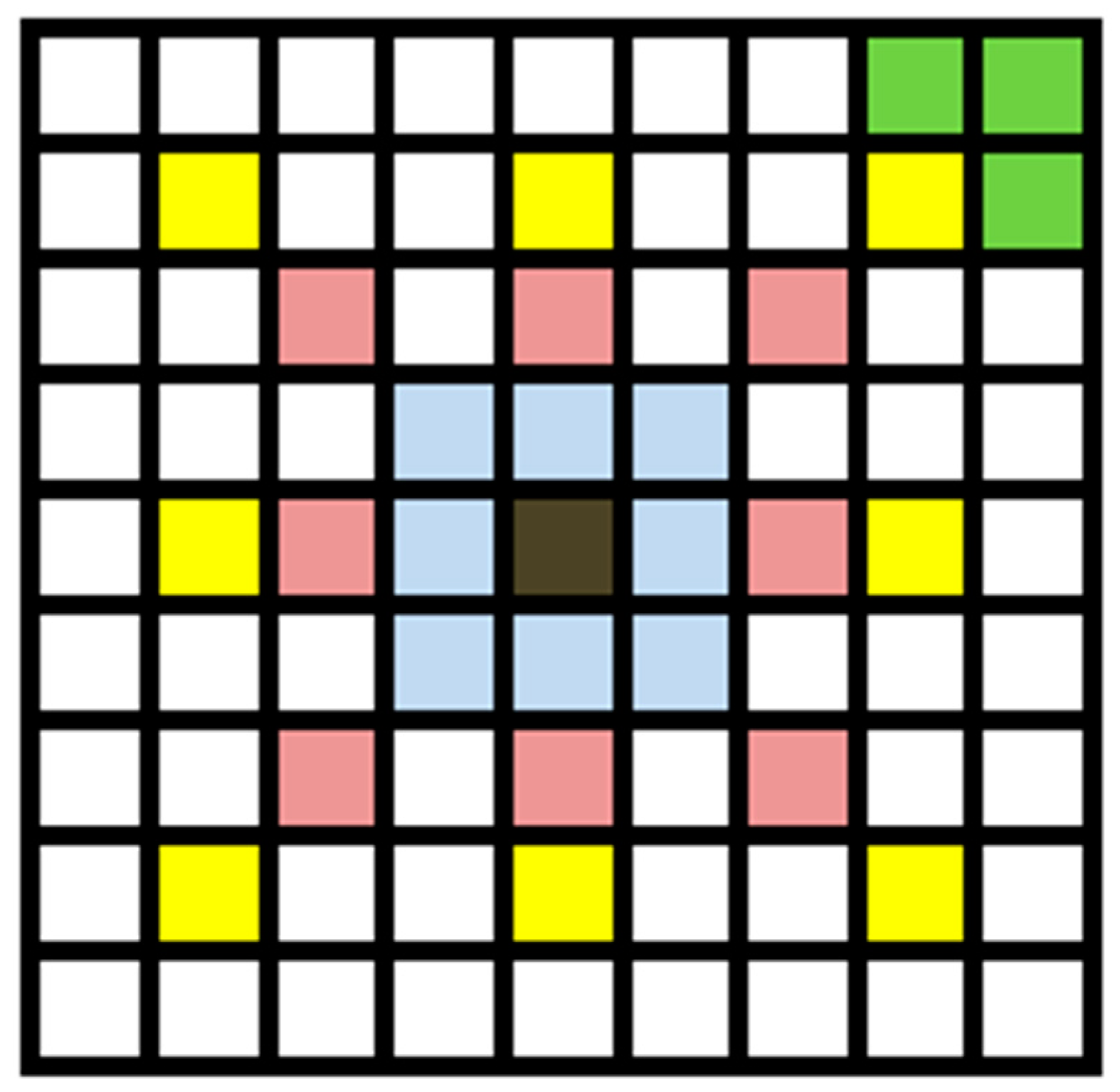
The neighbors at different diagonal levels are shown in Figure 5, where the center, third diagonal, fifth diagonal, and seventh diagonal are represented by brown, blue, pink, and yellow, respectively. Meanwhile, the vertical and horizontal pixels of a yellow central pixel are represented in green. The feature vector for the experiments was designed using a reduced concatenating histogram of each pattern, where each pattern histogram carries 20 bin-making feature vectors of 160 in length. The class misbalancing is a common phenomenon that occurs due to the smaller number of required samples in the concerned class in comparison to neighboring classes. The misbalancing can cause image retrieval issues as well. The arrays shown in Figure 3 and Figure 4 are actually windows of pixels taken from an RGB image in order to explain the local octa pattern algorithm.
In this study, the LOP’s main concern was to extract the elaborated image vectors. For this purpose, class misbalancing can be reduced by using a higher number of enhanced samples for training, resulting in enhanced precision with reduced misbalancing. If the | B | images are taken from the “n” number of classes, then the whole image dataset can be divided into S = { S 1   ,   S 2 , S 3 S n } subsets, where each subset has | B | s = | B | S × 0.3 images for each category (where 0.3 is a normalized ratio of images taken for training equivalent to 30%). All of the abovementioned subsets can be further categorized into two categories: positive | b | + and negative | b | samples, as provided in Equations (10) and (11) [41]:
| b | + = { j = 1 , 2 , 3 ,     | B S j | | K j | B S j | }
| b | = { j = 1 , 2 , 3 ,    | B S S j | | K j | B S S j | }
Equations (10) and (11) correspond to the division of positive and negative training samples, respectively, in order to enhance the precision. A classifier is normally trained on a set of positive samples and a set of negative samples generated by LOP. These equations explain that a subset is further divided into positive and negative samples before training through the classifier to reduce misbalancing.
It is important to have high-quality feature extraction for the fault detection applications in order to ensure better training of the data by the classifier. The misbalancing issue can pose serious challenges, and should be addressed through inclusion of a genetic algorithm. To avoid the classifier being misled due to the misbalancing, different sets—as mentioned in the above equations—can be used for training purposes through the AI-based genetic algorithm. Equations (12)–(18) are relevant to the genetic algorithm (GA). The genetic algorithm is actually used in order to increase the number of positive samples. It must be noted that if the number of training samples is enhanced, the classifier would be better trained, and better retrieval results can be obtained in return. In a genetic algorithm, genes with individual values (alleles) are combined to make chromosomes—also called decision variables—to find problems. The GA, as the name suggests, takes parent samples from a pool of positive samples and then creates offspring. Out of these offspring, only those that satisfy an evaluation test are selected and added to the parent sample pool. Equation (12) defines a chromosome that is actually a parent sample—or in this case is a feature vector of an image in database:
Θ = [ θ c , 1 , θ c , 2 , θ c , G ] , c = { 1 , 2 , , P }
where G represents the number of genes in a chromosome, and P represents the population size. In this work, the feature vectors of the original images were used as the initial population for the process, and the original images processed using LOP were used as the parent population. For the generation of the offspring population, various genetic operators are usually applied to the chromosomes, such as mutation [42], crossover [43], etc. The crossover technique can be subdivided into 2-point crossover and mid-point crossover. The 2-point crossover was used for the offspring population generation in this study. The new offspring were generated by exchanging the segments of 2 random parents and cutoff points. If Θ1 and Θ2 are the chromosomes of the selected parents, Θ1,off and Θ2,off are the chromosomes of the newly generated offspring, and p1 = {p1,1,p1,2,…p1,G}, p2 = {p2,1,p2,2,…p2,G} represent the two parents respectively, then new offspring can be formed using Equations (13)–(16) (where the crossovers or cutoff points are represented by C).
parents ( p ) [ 1 , 2 ] = rand ( 2 )
crossover ( C ) [ 1 , 2 ] = rand ( 2 )  
Θ 1 , off = [ θ p 1 , 1 θ p 1 , C 1 ; θ p 2 , C 1 θ p 2 , C 2 ; θ p 1 , C 2 θ p 1 , G ]  
Θ 2 , off = [ θ p 2 , 1 θ p 2 , C 1 ; θ p 1 , C 1 θ p 1 , C 2 ; θ p 2 , C 2 θ p 2 , G ]  
Equation (13) shows that 2 random parents are selected from the database, and Equation (14) shows that 2 random cutoff points are selected. After selecting 2 parents and 2 cut-off points, these 2 parents then cross over to make 2 new offspring. Equations (15) and (16) show the 2 new offspring as a result of the crossover. If the two parents have the same value—such as p1 = p2—then the generation loop of random offspring will keep running until 2 random parents with different values are processed. The whole procedure is then repeated for C1 = C2.
Equation (17) essentially shows an evaluation test for the offspring. After generating multiple offspring, only those offspring that are very close to the parents or—in mathematical terminology—have less distance than any of their parents, are selected. After passing the evaluation test, all of the newly generated offspring are ready to be part of the elite parent (e) population. In the next cycle, for the generation of new offspring as well as new iterations, this new elite population is selected.
Θ e = Θ off < Θ e = { p + 1 P }
Now, after generating multiple pools of selected offspring, only a specific pool is selected. Equation (18) shows that only the pool of offspring with the minimum average distance compared to the average distance of the original positive training sample pool is selected. In the current scenario, a population size of 150 was used. Furthermore, the following fitness function was used for the selection of the population taking part in the new offspring generation, which relies on the minimum threshold regarding the average distance from the original training sample:
J ( Θ j ) = arg   min ( F avg | b | + j F avg   Θ off j β
In Equation (18), the total population generated is represented by β, and the value β = 10 was used during the experiments. Initially, only the parent population was used to generate the chromosome population, whereas in the advanced step, the population under consideration was composed of the entire set of the elite population, including both the offspring and the elite parents. The complete summary of the genetic algorithm used in the proposed study is as follows (Algorithm 1):
Algorithm 1: Genetic algorithm (GA)
Input: positive image sample set | b | + ,images in database | D | S , β (number of generated populations), population size “PS”, genetic algorithm method “Gm”
  1. for j←1, β do
  2. Θ + genetic   algorithm   ( | b | + ) with   elite   parents   | b | +
  3. for k←1, PS/2 do
  4. [p1, p2] ←rand (2)
  5. [C1, C2] ←rand (2)
  6. Θ 1 , off = [ θ PS 1 , 1 θ PS 1 , C 1 ; θ PS 2 , C 1 θ PS 2 , C 2 ; θ PS 1 , C 2 θ PS 1 , G ]
  7. Θ 2 , off = [ θ PS 2 , 1 θ PS 2 , C 1 ; θ PS 1 , C 1 θ PS 1 , C 2 ; θ PS 2 , C 2 θ PS 2 , G ]
  8. if Gm = elitism asymmetric, then
  9. compute J ( Θ j ) = arg   min ( F | b | + j F Θ off j ) β
  10. else
  11. compute Θ e = Θ   off < Θ , e = { 1 P }
  12. compute J ( Θ j ) = arg   min ( F | b | + j F Θ off j ) β
  13. end if
  14. end for
  15. end for
Output: | b | + = | b | + + Θ off

2.3. Data Training Using the SVM Classifier

In the next stage, the newly generated features from LOP and GA are trained using an SVM classifier [44]. There are many other classifier options for the training of data, but the choice of the SVM classifier for training purposes in this work was due to the following reasons:
  • SVM works well when there is a clear margin of separation between classes;
  • SVM is memory-efficient as compared to other classifiers;
  • SVM has better computational complexity;
  • The execution time of SVM is very short.
In SVM, the relative positive feature vectors are initialized at the value 1, whereas other vectors are labeled as 0 to fully train the classifier for all categories of images. This is how the class association problem is addressed, and only those images with minimum distance w.r.t. the query image are returned to the user. After SVM classifier training, this method is fully set to effectively predict the motor’s operation and work state.

3. Results and Discussions

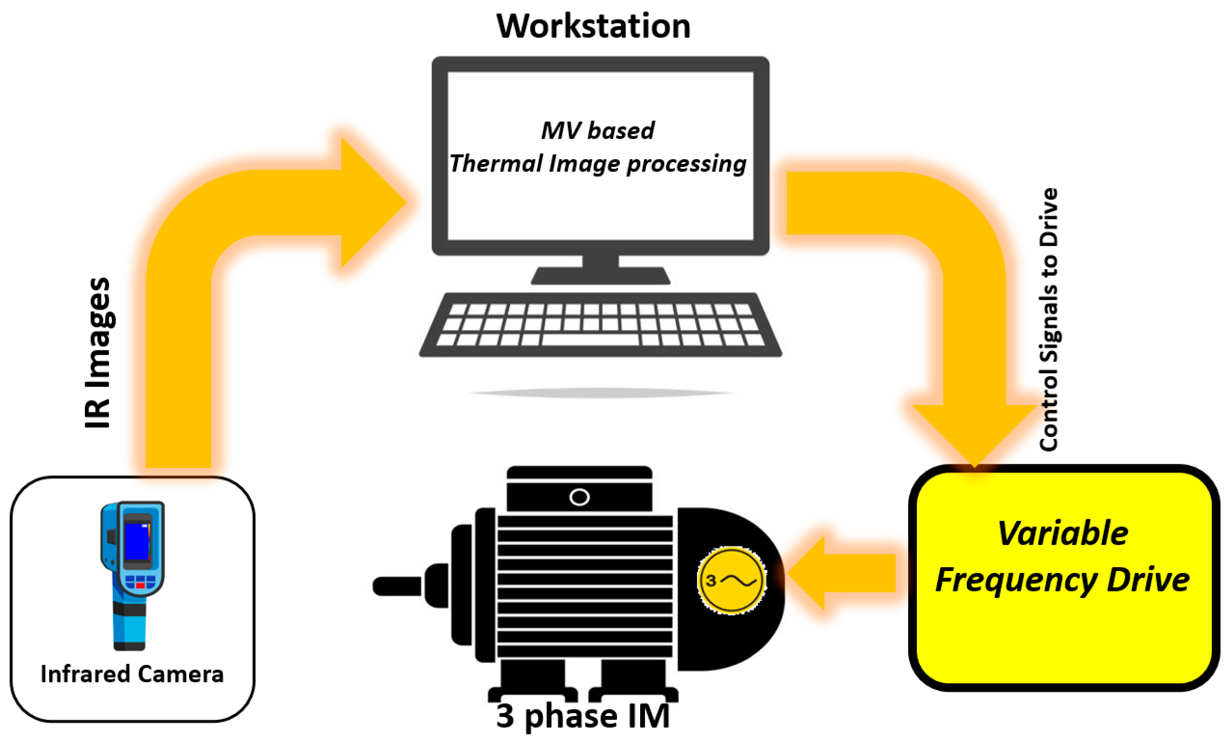
In order to validate the effectiveness of the proposed methodology (based on IRT and MV) of fault detection in IMs, it was applied on the experimental test bench, as presented in Figure 1. The experimental setup was composed of a three-phase 2 kW induction motor (powered with a three-phase supply) and an IR camera, both interfaced with a central workstation. The workstation was connected with the IM through a variable-frequency drive, and could generate control signals for the frequency drive to control the IM speed. The workstation contained the trained data generated through IRT and MV for different working conditions of the IM, as already explained in detail in the previous sections. The complete flow diagram of the test bench is provided in Figure 6. According to Figure 6, the thermal image of the IM was captured and transmitted to the workstation to determine the working state of the IM. The workstation looks up the image in the trained data and issues control signals to the drive accordingly for the control of the IM.
In this work, the IM was diagnosed under different conditions, and the corresponding results were generated and validated after detailed analysis in order to calculate the accuracy in a precise manner. The different operating conditions introduced for the IM in the experimental setup were normal operation, overload, and short-circuit. For instance, a short-circuit fault was introduced in the IM by short-circuiting the winding, which caused a rise in the heat profile of the IM. A thermal image was captured and sent to workstation for assessment through MV. The workstation declared the “fault condition” for the IM after the required processing of the thermal image. Meanwhile, the control signal was also issued to frequency drive in order to protect the IM from faults. The proposed method was validated for all three of the abovementioned conditions in the experimental test bench. The experimental setup was able to provide an accuracy level greater than 90% for all three scenarios, which is obviously a reasonable precision level. For this purpose, multiple iterations of the experimentation were carried out for the validation of the proposed algorithm under different conditions. A suitable database was selected and stored initially for the design of the retrieval system by capturing hundreds of IR images of the IM under the three considered scenarios, i.e., normal condition, overloaded condition, and fault condition. After the induction of the trained system in the scenario for fault detection, the retrieval system performance was calculated using the evaluation parameters “precision rate” and “recall rate” provided in Equations (19) and (20), respectively. The evaluation rate of precision can be defined as follows:
P = R ret T ret
where the precision rate is represented by P, the total number of relevant retrieved images is represented by R ret , and the total number of retrieved images is represented by T ret . Likewise, the recall rate R can be defined as follows:
R = R ret T rel
where the recall rate is represented by R, the total number of relevant images retrieved is represented by R ret , and T rel represents the total number of relevant images.
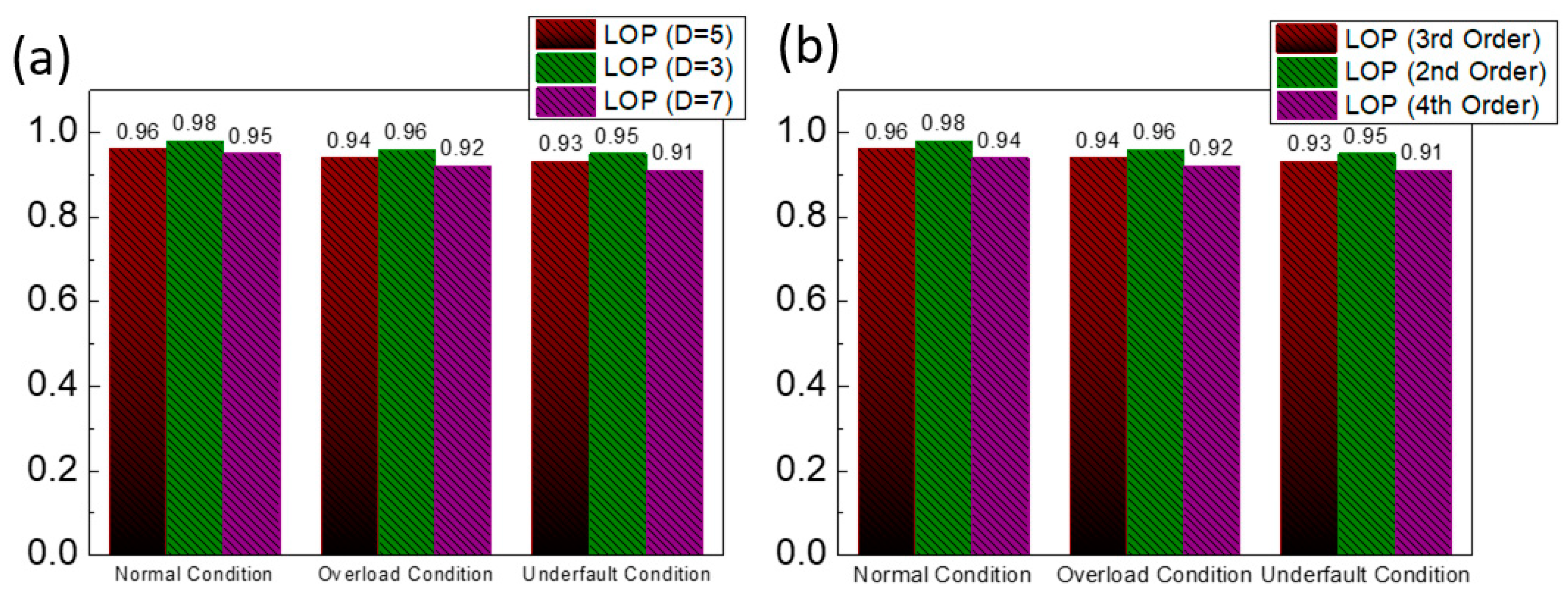
It is worth mentioning that, in this work, 12 random images from the dataset of hundreds of thermal images were selected for each of the three scenarios (for a total of 36 images for feature extraction and training). The top 30 images were retrieved to calculate the precision and recall rate based on the results of seven iterations. For LOP, experiments were also performed to predict the performance of the feature-extraction technique by changing the diagonal neighbors and order of the LOP. First of all, the experiments on the local octa pattern (2nd-order) with neighbors at diagonals (D) 3, 5, and 7 were performed for the three different operating conditions of the IM, as shown in Figure 7. Figure 7a shows that the precision rates for a neighbor at diagonal 3 are highly precise and accurate for all three operating conditions of the IM, as compared to diagonals 5 and 7. Later on, the second set of experiments were performed by keeping in mind diagonal (D) = 3 only, and changing the order (2nd, 3rd, and 4th) of the LOP. The variations in precision rate between different orders of LOP performance for the various conditions can be seen in Figure 7b, and the results obtained in Figure 7b show that the neighbor at diagonal 3 was highly accurate with 2nd-order LOP for all three conditions.
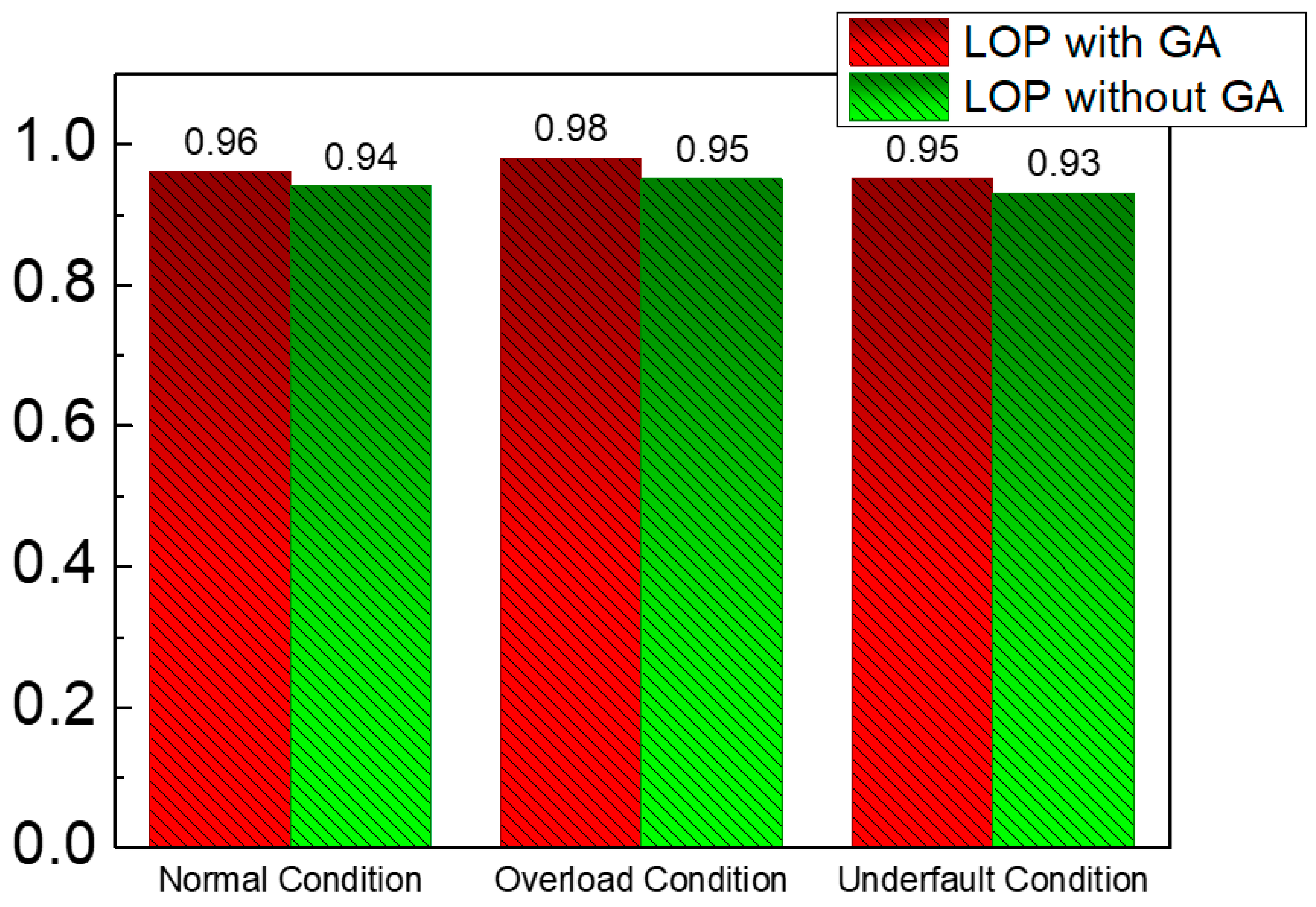
As mentioned before, a GA was used with LOP in this work to achieve high-quality feature extraction. Therefore, to verify the benefit of the GA’s inclusion with LOP for feature extraction, a comparative study of the LOC with and without the use of the genetic algorithm was also carried out for the normal, overload, and fault conditions of the IM, as shown in Figure 8. It is evident from Figure 8 that higher precision is attainable by the inclusion of the genetic algorithm with LOP for the normal, overload, and fault conditions of the IM. In the end, to further affirm the superiority and effectiveness of the proposed method compared to existing techniques, a comparative study was performed, as summarized in Figure 9 and Table 3. Figure 9 affirms the outstanding performance and accuracy of the purposed method for fault detection as compared to MLP, ANN, MLP with graph-cut, and SVM. This method is able to provide an accuracy rate of 0.97, which is obviously high, and this level of accuracy also endorses its reliability for implementation in industry for fault-detection purposes.

4. Conclusions

This work presents the idea of fault diagnosis for an induction motor by incorporating the technique of infrared thermography with machine vision. The obtained results show that the proposed methodology was able to detect the operating mode of the IM under three different conditions of motor operation. In this work, initially, the dataset of thermal images was generated, and was later processed through LOP and SVM in order to perform the automated fault detection of industrial loads. The results further verified that the machine-learning-based feature extraction for the fault detection in an IM is quite useful in comparison to previous techniques, because it detects the faults without overall system shutdown, and avoids energy and economic losses. It was also found that the feature-extraction quality of LOP can be further enhanced if used along GA. In this work, the proposed methodology was also validated by generating an experimental test bench and introducing three scenarios (normal operation, overload, and fault) for the IM. The experimental validation affirmed the effectiveness of the method by diagnosing the working condition of the IM accurately. Overall, it may be concluded from the whole discussion that the inclusion of machine vision with IRT for fault detection provided high accuracy and precision rates as compared to other techniques. Furthermore, this algorithm can be easily implemented with minor changes to other fault-detection applications existing in industrial systems, such as inverters, switching faults, etc.

Author Contributions

Conceptualization, M.R.J., Z.S., F.A., W.A., F.M., M.O.K., U.S.V., A.W. and Z.M.H.; Formal analysis, Z.S., F.A., U.S.V., A.W. and Z.M.H.; Methodology, W.A., F.M. and M.O.K.; Writing—original draft, M.R.J.; Writing—review & editing, F.A., A.W. and Z.M.H. All authors have read and agreed to the published version of the manuscript.

Funding

This research work was supported by the Office of Research Innovation and Commercialization (ORIC), The Islamia University of Bahawalpur, Pakistan (No. 3900/ORIC/IUB/2021).

Institutional Review Board Statement

Not applicable.

Informed Consent Statement

Not applicable.

Acknowledgments

We are very grateful to the Power Systems Lab, and Chairman, Department of Electrical Engineering, UET, Faisalabad Campus to provide the testing facilities. The Authors further acknowledge the Department of Energy Systems Engineering, University of Agriculture, Faisalabad and the Office of Research Innovation and Commercialization (ORIC), The Islamia University of Bahawalpur, Pakistan (No. 3900/ORIC/IUB/2021) for their support in this research.

Conflicts of Interest

The authors declare no conflict of interest.

Abbreviations

InductionmotorIM
Infrared thermographyIRT
Local octa patternLOP
Support-vector machineSVM
Run-to-failureRTF
Artificial intelligenceAI
Artificial neural networkANN
Multilayer perceptionMLP
Local tetra patternLTP
Genetic algorithmGA
Machine visionMV

References

  1. Malekpour, M.; Phung, B.; Ambikairajah, E. Online technique for insulation assessment of induction motor stator windings under different load conditions. IEEE Trans. Dielectr. Electr. Insul. 2017, 24, 349–358. [Google Scholar] [CrossRef]
  2. Huda, A.N.; Taib, S. Application of infrared thermography for predictive/preventive maintenance of thermal defect in electrical equipment. Appl. Therm. Eng. 2013, 61, 220–227. [Google Scholar] [CrossRef]
  3. Kim, Y.-H.; Youn, Y.-W.; Hwang, D.-H.; Sun, J.-H.; Kang, D.-S. High-Resolution Parameter Estimation Method to Identify Broken Rotor Bar Faults in Induction Motors. IEEE Trans. Ind. Electron. 2012, 60, 4103–4117. [Google Scholar] [CrossRef]
  4. Arkan, M.; Kostic-Perovic, D.; Unsworth, P. Modelling and simulation of induction motors with inter-turn faults for diagnostics. Electr. Power Syst. Res. 2005, 75, 57–66. [Google Scholar] [CrossRef]
  5. Hong, J.; Park, S.; Hyun, D.; Kang, T.J.; Lee, S.B.; Kral, C.; Haumer, A. Detection and classification of rotor demagnetization and eccentricity faults for PM synchronous motors. IEEE Trans. Ind. Appl. 2012, 48, 923–932. [Google Scholar] [CrossRef]
  6. Torkaman, H.; Afjei, E.; Yadegari, P. Static, Dynamic, and Mixed Eccentricity Faults Diagnosis in Switched Reluctance Motors Using Transient Finite Element Method and Experiments. IEEE Trans. Magn. 2012, 48, 2254–2264. [Google Scholar] [CrossRef]
  7. Leite, V.C.; Da Silva, J.G.B.; Veloso, G.F.C.; Da Silva, L.E.B.; Lambert-Torres, G.; Bonaldi, E.L.; De Lacerda De Oliveira, L.E. Detection of Localized Bearing Faults in Induction Machines by Spectral Kurtosis and Envelope Analysis of Stator Current. IEEE Trans. Ind. Electron. 2015, 62, 1855–1865. [Google Scholar] [CrossRef]
  8. Eftekhari, M.; Moallem, M.; Sadri, S.; Shojaei, A. Review of induction motor testing and monitoring methods for inter-turn stator winding faults. In Proceedings of the 2013 21st Iranian Conference on Electrical Engineering (ICEE), Mashhad, Iran, 14–16 March 2013; pp. 1–6. [Google Scholar]
  9. Gyftakis, K.N.; Drif, M.; Cardoso, A.J.M. Thorough investigation of the third current harmonic in delta-connected induction motors suffering from a stator inter-turn fault. In Proceedings of the 2015 IEEE 10th International Symposium on Diagnostics for Electrical Machines, Power Electronics and Drives (SDEMPED), Guarda, Portugal, 1–4 September 2015; pp. 7–13. [Google Scholar]
  10. Kawady, T.A.; Afify, A.A.; Osheiba, A.M.; Taalab, A.I. Modeling and Experimental Investigation of Stator Winding Faults in Induction Motors. Electr. Power Compon. Syst. 2009, 37, 599–611. [Google Scholar] [CrossRef]
  11. Chen, B.; Wan, J.; Xia, M.; Zhang, Y. Exploring Equipment Electrocardiogram Mechanism for Performance Degradation Monitoring in Smart Manufacturing. IEEE/ASME Trans. Mechatron. 2020, 25, 2276–2286. [Google Scholar] [CrossRef]
  12. Ge, Z.; Du, X.; Yang, L.; Yang, Y.; Li, Y.; Jin, Y. Performance monitoring of direct air-cooled power generating unit with infrared thermography. Appl. Therm. Eng. 2011, 31, 418–424. [Google Scholar] [CrossRef]
  13. Lahiri, B.; Bagavathiappan, S.; Jayakumar, T.; Philip, J. Medical applications of infrared thermography: A review. Infrared Phys. Technol. 2012, 55, 221–235. [Google Scholar] [CrossRef] [PubMed]
  14. Royo, R.; Albertos-Arranz, M.A.; Cárcel-Cubas, J.A.; Payá, J. Thermographic study of the preheating plugs in diesel engines. Appl. Therm. Eng. 2012, 37, 412–419. [Google Scholar] [CrossRef]
  15. Manana, M.; Arroyo, A.; Ortiz, A.; Renedo, C.; Perez, S.; Delgado, F. Field winding fault diagnosis in DC motors during manufacturing using thermal monitoring. Appl. Therm. Eng. 2011, 31, 978–983. [Google Scholar] [CrossRef]
  16. Tsanakas, J.A.; Ha, L.; Buerhop, C. Faults and infrared thermographic diagnosis in operating c-Si photovoltaic modules: A review of research and future challenges. Renew. Sustain. Energy Rev. 2016, 62, 695–709. [Google Scholar] [CrossRef]
  17. Roslidar, R.; Rahman, A.; Muharar, R.; Syahputra, M.R.; Arnia, F.; Syukri, M.; Pradhan, B.; Munadi, K. A Review on Recent Progress in Thermal Imaging and Deep Learning Approaches for Breast Cancer Detection. IEEE Access 2020, 8, 116176–116194. [Google Scholar] [CrossRef]
  18. Doshvarpassand, S.; Wu, C.; Wang, X. An overview of corrosion defect characterization using active infrared thermography. Infrared Phys. Technol. 2018, 96, 366–389. [Google Scholar] [CrossRef]
  19. Nardi, I.; Lucchi, E.; de Rubeis, T.; Ambrosini, D. Quantification of heat energy losses through the building envelope: A state-of-the-art analysis with critical and comprehensive review on infrared thermography. Build. Environ. 2018, 146, 190–205. [Google Scholar] [CrossRef] [Green Version]
  20. ElMasry, G.; ElGamal, R.; Mandour, N.; Gou, P.; Al-Rejaie, S.; Belin, E.; Rousseau, D. Emerging thermal imaging techniques for seed quality evaluation: Principles and applications. Food Res. Int. 2020, 131, 109025. [Google Scholar] [CrossRef]
  21. Glowacz, A. Ventilation Diagnosis of Angle Grinder Using Thermal Imaging. Sensors 2021, 21, 2853. [Google Scholar] [CrossRef]
  22. Chou, Y.-C.; Yao, L. Automatic Diagnostic System of Electrical Equipment Using Infrared Thermography. In Proceedings of the 2009 International Conference of Soft Computing and Pattern Recognition, Malacca, Malaysia, 4–7 December 2009; pp. 155–160. [Google Scholar]
  23. Singh, G.; Naikan, V. Infrared thermography based diagnosis of inter-turn fault and cooling system failure in three phase induction motor. Infrared Phys. Technol. 2017, 87, 134–138. [Google Scholar] [CrossRef]
  24. Manduchi, G.; Marinetti, S.; Bison, P.; Grinzato, E. Application of neural network computing to thermal non-destructive evaluation. Neural Comput. Appl. 1997, 6, 148–157. [Google Scholar] [CrossRef]
  25. Kumar, R.; Raj, L.G.C.; Abarna, J. Analysis of Fuzzy Logic Based Fault Detection for Three Phase Induction Motor Drive System. In Proceedings of the 2018 4th International Conference on Electrical Energy Systems (ICEES), Chennai, India, 7–9 February 2018; pp. 700–705. [Google Scholar]
  26. Hussan, U.; Majeed, M.A.; Asghar, F.; Waleed, A.; Khan, A.; Javed, M.R. Fuzzy logic-based voltage regulation of hybrid energy storage system in hybrid electric vehicles. Electr. Eng. 2021, 104, 485–495. [Google Scholar] [CrossRef]
  27. Javed, M.R.; Waleed, A.; Virk, U.S.; Hassan, S.Z.U. Comparison of the Adaptive Neural-Fuzzy Interface System (ANFIS) based Solar Maximum Power Point Tracking (MPPT) with other Solar MPPT Methods. In Proceedings of the 2020 IEEE 23rd International Multitopic Conference (INMIC), Bahawalpur, Pakistan, 5–7 November 2020; pp. 1–5. [Google Scholar]
  28. Idrees, M.; Riaz, M.T.; Waleed, A.; Paracha, Z.J.; Raza, H.A.; Khan, M.A.; Hashmi, W.S. Fuzzy Logic Based Calculation and Analysis of Health Index for Power Transformer Installed in Grid Stations. In Proceedings of the 2019 International Symposium on Recent Advances in Electrical Engineering (RAEE), Islamabad, Pakistan, 28–29 August 2019; Volume 4, pp. 1–6. [Google Scholar] [CrossRef]
  29. Darabi, A.; Maldague, X. Neural network based defect detection and depth estimation in TNDE. NDT E Int. 2002, 35, 165–175. [Google Scholar] [CrossRef]
  30. Almeida, C.A.L.; Braga, A.P.; Nascimento, S.; Paiva, V.; Martins, H.J.A.; Torres, R.; Caminhas, W.M. Intelligent Thermographic Diagnostic Applied to Surge Arresters: A New Approach. IEEE Trans. Power Deliv. 2009, 24, 751–757. [Google Scholar] [CrossRef]
  31. Kumar, P.; Hati, A.S. Review on Machine Learning Algorithm Based Fault Detection in Induction Motors. Arch. Comput. Methods Eng. 2020, 28, 1929–1940. [Google Scholar] [CrossRef]
  32. Jia, Z.; Liu, Z.; Vong, C.-M.; Pecht, M. A Rotating Machinery Fault Diagnosis Method Based on Feature Learning of Thermal Images. IEEE Access 2019, 7, 12348–12359. [Google Scholar] [CrossRef]
  33. Rao, P.N.; Kumar, N.M.; Padmanaban, S.; Subathra, M.S.P.; Chand, A.A. A Novel Sensorless Approach for Speed and Displacement Control of Bearingless Switched Reluctance Motor. Appl. Sci. 2020, 10, 4070. [Google Scholar] [CrossRef]
  34. Shafi’i, M.A.; Hamzah, N. Internal fault classification using artificial neural network. In Proceedings of the 2010 4th International Power Engineering and Optimization Conference (PEOCO), Shah Alam, Malaysia, 23–24 June 2010; pp. 352–357. [Google Scholar]
  35. Ullah, I.; Yang, F.; Khan, R.; Liu, L.; Yang, H.; Gao, B.; Sun, K. Predictive Maintenance of Power Substation Equipment by Infrared Thermography Using a Machine-Learning Approach. Energies 2017, 10, 1987. [Google Scholar] [CrossRef] [Green Version]
  36. Rahmani, A.; Haddadnia, J.; Seryasat, O. Intelligent fault detection of electrical equipment in ground substations using thermo vision technique. In Proceedings of the 2010 2nd International Conference on Mechanical and Electronics Engineering, Kyoto, Japan, 1–3 August 2010; Volume 2, pp. V2-150–V2-154. [Google Scholar]
  37. Shabbir, Z.; Irtaza, A.; Javed, A.; Mahmood, M.T. Tetragonal Local Octa-Pattern (T-LOP) based image retrieval using genetically optimized support vector machines. Multimed. Tools Appl. 2019, 78, 23617–23638. [Google Scholar] [CrossRef]
  38. Murala, S.; Maheshwari, R.P.; Balasubramanian, R. Local Tetra Patterns: A New Feature Descriptor for Content-Based Image Retrieval. IEEE Trans. Image Process. 2012, 21, 2874–2886. [Google Scholar] [CrossRef]
  39. Asghar, F.; Talha, M.; Kim, S.H. Neural Network Based Fault Detection and Diagnosis System for Three-Phase Inverter in Variable Speed Drive with Induction Motor. J. Control Sci. Eng. 2016, 2016, 1286318. [Google Scholar] [CrossRef] [Green Version]
  40. Talha, M.; Asghar, F.; Kim, S.H. A Novel Three-Phase Inverter Fault Diagnosis System Using Three-dimensional Feature Extraction and Neural Network. Arab. J. Sci. Eng. 2018, 44, 1809–1822. [Google Scholar] [CrossRef]
  41. Irtaza, A.; Jaffar, M.A. Categorical image retrieval through genetically optimized support vector machines (GOSVM) and hybrid texture features. Signal Image Video Process. 2014, 9, 1503–1519. [Google Scholar] [CrossRef]
  42. Arevalillo-Herráez, M.; Ferri, F.J.; Moreno-Picot, S. Distance-based relevance feedback using a hybrid interactive genetic algorithm for image retrieval. Appl. Soft. Comput. 2011, 11, 1782–1791. [Google Scholar] [CrossRef]
  43. Herrera, F.; Lozano, M. Hybrid crossover operators for real-coded genetic algorithms: An experimental study. Soft Comput. 2004, 9, 280–298. [Google Scholar] [CrossRef]
  44. Hearst, M.A.; Dumais, S.T.; Osuna, E.; Platt, J.; Scholkopf, B. Support vector machines. IEEE Intell. Syst. Appl. 1998, 13, 18–28. [Google Scholar] [CrossRef] [Green Version]
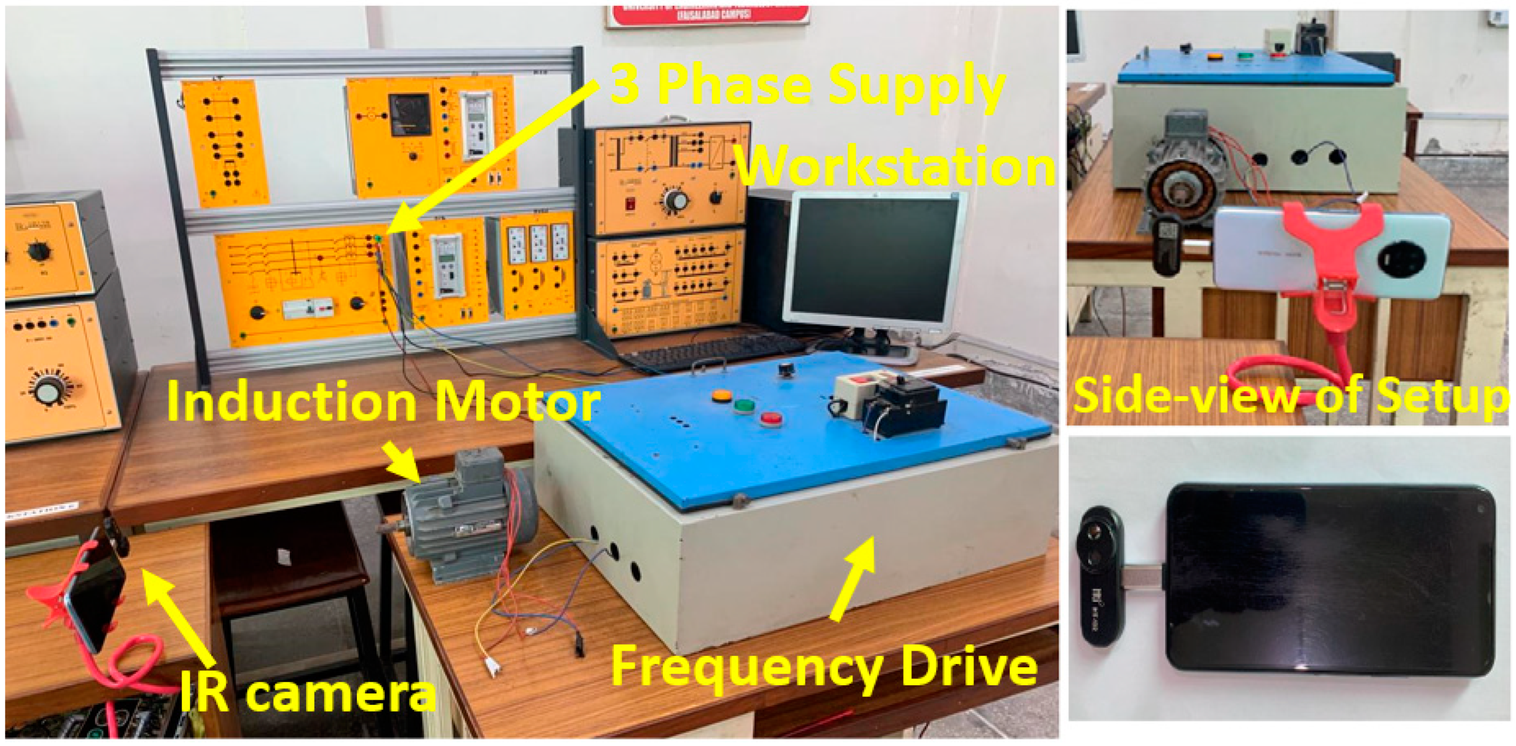
Figure 1. The figure shows different views of the experimental setup, assembled for capturing the thermal images of the IM using IRT. This experimental setup was also used for the purpose of the proposed method’s validation.
Sustainability 14 09060 g001
Figure 2. Thermal images of the induction motor captured under various conditions for the data acquisition stage: (a) normal operating condition, (b) overloaded condition, and (c) fault condition.
Sustainability 14 09060 g002
Figure 3. The complete flowchart of the proposed fault-diagnosis technique.
Sustainability 14 09060 g003
Figure 4. The figure presents the feature extraction and the pattern recognition using the local octa pattern (LOP) algorithm.
Sustainability 14 09060 g004
Figure 5. The figure describes the defining of neighborhoods using tetragonal octa patterns for pictorial explanation.
Sustainability 14 09060 g005
Figure 6. Figure showing the schematic diagram of the experimental setup used to validate the proposed method based on IRT and MV.
Sustainability 14 09060 g006
Figure 7. The performance comparison of LOP with different orders and diagonal neighbors: (a) The comparative analysis of the precision rate using LOCP (2nd-order) with neighbors at diagonals 3, 5, and 7. (b) The comparative analysis of the precision rate using LOCP for different orders of the LOCP.
Sustainability 14 09060 g007
Figure 8. The comparison of the precision rates for LOP, with and without genetic algorithm (GA), for three different operating conditions of the IM.
Sustainability 14 09060 g008
Figure 9. The comparative analysis of accuracy of the proposed algorithm and existing techniques for fault-detection purposes.
Sustainability 14 09060 g009
Table 1. The specifications of the three-phase IM.
No.ParameterSpecification (Value)
1Rated Power2 kW
2Rated Frequency50 Hz
3Stator Resistance1.47 Ω
4Rotor Resistance1.39 Ω
5Magnetizing Reactance54.1 Ω
6Rated Speed1410 RPM
7Efficiency87%
Table 2. The state of the IM based on ΔT.
No.State of MotorΔTRecommended Action
1Normal Operating Condition30 < T < 45No Need for Action
2Overloaded Condition45 < T < 63Wait for Some Time
3Fault ConditionT > 65Shut Down
Table 3. The comparison of the accuracy of the proposed method with the existing techniques reported in the literature.
No.MethodAccuracy
1Proposed Method0.97
2Multilayer Perceptron (MLP)0.8
3MLP with Graph-Cut0.84
4ANN Classifier [34]0.93
5SVM [36]0.83
Publisher’s Note: MDPI stays neutral with regard to jurisdictional claims in published maps and institutional affiliations.