Article

Foundation Settlement Response of Existing High-Speed Railway Bridge Induced by Construction of Undercrossing Roads

1
School of Civil Engineering, Central South University, Changsha 410075, China
2
Dongguan Comprehensive Traffic Operation Command Center, Dongguan 523125, China
*
Author to whom correspondence should be addressed.
Sustainability 2022, 14(14), 8700; https://doi.org/10.3390/su14148700
Submission received: 20 June 2022 / Revised: 10 July 2022 / Accepted: 14 July 2022 / Published: 15 July 2022
(This article belongs to the Special Issue Analysis and Modeling for Sustainable Geotechnical Engineering)

Abstract

:
The construction of undercrossing roads often has an adverse effect on the upper existing railway line, and can cause an uneven subsidence of the crossed section. In response to the influence of new road construction on the existing high-speed railway bridge, a highway passing under an existing high-speed railway bridge was taken as the research object. Based on the FLAC3D finite difference software, a computational model of new roads undercrossing a high-speed railway bridge was established to analyze the structural deformation response of a high-speed railway bridge. The results show that the excavation of foundation pits during new road construction causes an overall upward heaving of the soil layers between the pits, with a greater amount of heaving near the high-speed railway piers than that at other locations. Meanwhile, a degree of upward displacement of the high-speed railway bridge piers occurred. The filling of a road base structure generates an additional stress greater than the original consolidation pressure, inducing an overall subsidence of the soil layers between the pits. The final deformation during construction of new roads undercrossing the high-speed railway bridge shows that the displacement of adjacent piles is manifested as an overall settlement and as a horizontal displacement to the side of soil excavation.

Graphical Abstract

1. Introduction

In China, the construction of roads and railways is developing rapidly in transport construction. Due to the old and new line planning, the environmental and economic benefits and other factors of engineering construction, namely crossings of road lines with railway lines, are inevitable. For instance, new roads undercrossing a high-speed railway bridge are more common [1,2,3]. A new construction may cause a disturbance to the nearby strata. Since project construction is closer to structures such as piers, bases, and pile foundations of a high-speed railway bridge, the safety and stability of the existing high-speed railway must be ensured during construction.
The excavation of new line engineering causes an unloading of the soil layer, which leads to a surface settlement around the pit. A large number of theoretical analysis methods have been proposed regarding the surface settlement caused by the excavation of soil layers [4,5,6,7,8,9,10]. Peck [4] and Capse [5] proposed the empirical formulas for ground settlement of the soil outside the pit for different soil layers based on the ground settlement monitoring data in the field, which laid a theoretical foundation for subsequent study. Clough [6] summarized the settlement patterns of different soil categories due to pit excavation and obtained the distribution patterns of ground settlement boundaries outside the pit for different categories of soils. Chen and Cao [7] analyzed the deformation characteristics during an unloading-reloading process of soft clay soils in foundation pit projects in Shanghai and proposed a calculation formula for estimating the rebound and full compensation settlement of soil, which enriched the theoretical study of soil excavation. Yi et al. [10] combined the random field theory and numerical simulation to analyze the deformations of a surface and subsurface diaphragm wall caused by foundation excavation. Three main analysis methods are commonly used, including the limit equilibrium method used in foundation pit engineering, the vertical beam method on elastic foundations used in specifications, and the numerical simulation analysis method based on continuum mechanics. Recently, the influence of the excavation of soil layers of foundation works on surrounding buildings has been widely discussed. A new excavation breaks the balance of ground stresses in the original soil layers and results in an uneven settlement of the existing buildings, which can lead to a tilting or even fracture of existing buildings. Liang et al. [11] used a centrifugal model to carry out tests of foundation excavation on adjacent metro tunnels and analyzed the deformation mechanisms of the underground diaphragm wall and metro tunnel during foundation excavation. Relying on an actual project, Xue et al. [12] carried out field tests to study the ground deformation law caused by the water-soil barrier effect of existing structures during foundation excavation. Luo [13] established a dynamic analysis model of the coupled system considering pit excavation and obtained the dynamic impact of pit excavation on the existing railway line. According to the actual project, Yu [14] used Abaqus finite element software to simulate the construction steps for excavation of the foundation pits supported by large diameter ring beams and obtained the influence law of the foundation pit support system on the surrounding environment. Yuan [15] used MIDAS/GTS software to conduct a numerical simulation of a deep and large foundation excavation in a water-rich area and analyzed the distribution law of seepage in a deep foundation pit and the surface settlement law of the soil around a foundation pit during construction.
When a new line crosses an existing line, the construction of the new line underneath will unload the original soil layer, resulting in a displacement of the surrounding soil and thus having a significant impact on the upper buildings (structures). The research into the interaction in crossing construction has always received an extensive attention [3,16,17,18,19,20]. As the construction of a new line inevitably has an impact on the existing buildings, the new line needs to ensure the safety and stability of the existing buildings during construction. Wang et al. [21] simulated the construction of shield undercrossing railway bridge culverts and summarized the deformation characteristics of railway bridge structures using FLAC3D. Wang et al. [22] investigated the foundation displacement of new bridges underneath high-speed rail bridges and evaluated the interaction between old and new projects by simulating different construction sequences and distances. Xiao et al. [23] carried out a field trial study to investigate the effect of an undercrossing construction on existing high-speed railway bridges and concluded that the lateral deformation of high-speed railway structures was more significant than the vertical settlement during undercrossing construction. Yang and Wang [24] investigated the impact of a new metro tunnel on an existing pedestrian underpass by simulating the excavation process of a metro tunnel and analyzing the deformation and stress distribution in the pedestrian underpass caused by the new line undercutting the existing pedestrian underpass. Zhao et al. [25] established a model of a shield tunnel undercrossing a high-speed railway tunnel to analyze the force and deformation effects of the underpass construction on existing tunnel structures. Huang et al. [26] set up a test section of a shield tunnel undercrossing an existing high-speed railway tunnel to determine the reasonable parameters for shield underpass construction as a means of ensuring the safety of the existing tunnel. Lee [27] used 3D finite element software to analyze the underpasses under the adjacent bridge and quantified the deformation effect of underpass construction on the adjacent pier structures.
Numerous studies have shown that new excavation of foundation pits can break the original soil equilibrium, lead to soil movement and deformation, and result in an uneven settlement [28,29,30]. The excavation during the construction of a new line project undercrossing the existing engineering structure unloads the original soil layer, thus causing a deformation of the existing engineering structure and a surface settlement of the surrounding soil and resulting in a disturbance for the upper existing engineering structure. These studies mainly focus on the deformation law of existing structures caused by new tunnels undercrossing the existing structures. Few studies have been conducted on the multiple roads undercrossing a high-speed railway bridge and their deformation response to adjacent bridge structures. High-speed railways are characterized by high safety, speed, and comfort, and their requirements for the track regularity are relatively high [31]. The construction of new roads undercrossing an existing high-speed railway bridge, including an excavation of foundation pits, drilling and grouting of piles, and a construction of pavement structures, can cause a non-negligible disturbance to the nearby strata. A small spacing construction between the multiple roads may make the local layer loss more concentrated and increase the additional stress and differential settlement of the bridge structures. It consequently causes the irregularities in the ballast-less track on the bridge and affects the safety and comfort of the high-speed train traffic. Therefore, to investigate the deformation in foundation structure of an existing high-speed railway bridge and the displacement law of surrounding soil caused by the construction of new multiple roads undercrossing an existing high-speed railway bridge, this study established a numerical simulation model for the multiple roads undercrossing a high-speed railway bridge based on an engineering example and using FLAC3D software. Furthermore, the deformation response law of the foundation structure caused by new multiple roads undercrossing an existing high-speed railway bridge was also investigated based on actual engineering monitoring data and numerical simulation. The research framework of this paper is shown in Figure 1.
Section 1 of this paper organizes and analyzes the interaction between the new line project and the existing project. Section 2 introduces the engineering overview of the study area, including the form of the new roads undercrossing the high-speed railway bridge and the hydrogeological conditions of the project site. Section 3 introduces the theoretical analysis of the soil displacement outside the pit caused by the excavation of the foundation pit and the theory of pile-soil interaction. Section 4 establishes a numerical simulation model of new roads undercrossing an existing high-speed railway bridge, and analyzes the deformation and stress of the foundation structure of the high-speed railway bridge and surrounding soil layer caused by the construction of the new undercrossing roads. The article finishes with conclusions. The nomenclature section can be found at the end.

2. Overview of Study Area

The new roads considered in this study are located in a province in central China, the alluvial fan plain of the Yellow River, which includes a two-way six-lane urban trunk road and a two-way two-lane secondary road. The new roads pass under a multi-span simply supported bridge in the interval section of the Beijing-Guangzhou high-speed railway, with farmland on both sides of the bridge. The plane alignment of the high-speed railway at the undercrossing section is on a straight line and the longitudinal slope of the bridge is 0.05%. The groundwater at the project site is buried at a depth of about 10 m, which belongs to the Quaternary pore-diving type. As the groundwater level in the study area is deep and the excavation depth of the road foundation pit is around 1.1 m, the construction of the new roads undercrossing the existing high-speed railway bridge has a small influence on the distribution of the groundwater level and therefore does not cause too much change in the seepage field of the soil to generate additional stresses. Therefore, the influence of the groundwater level was not considered in the analysis of the deformation response of the existing high-speed railway bridge induced by construction of undercrossing roads in this study.

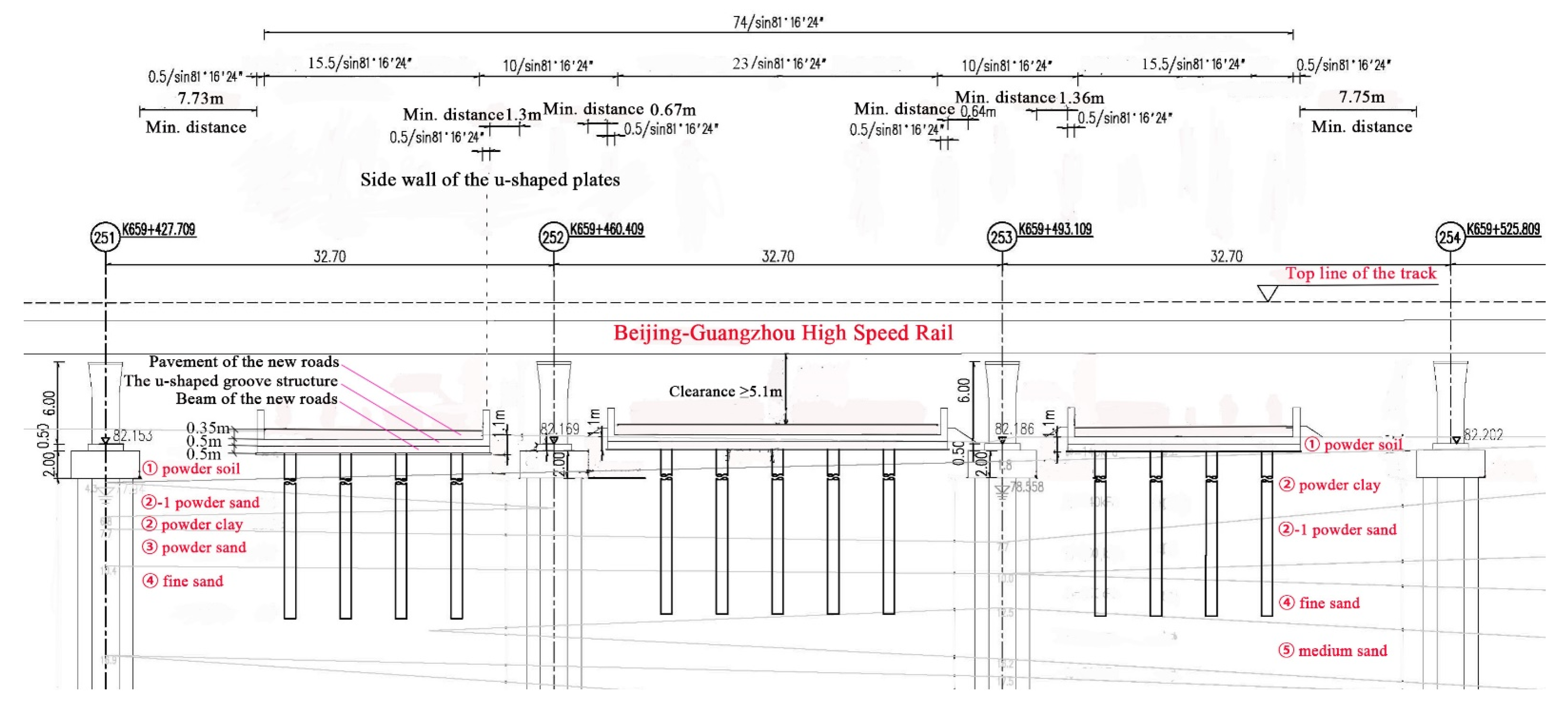
2.1. Project Overview

The superstructure of the Beijing-Guangzhou high-speed railway bridge at the undercrossing section adopts a simply supported beam with a span of 32 m. The substructure pier adopts a double-line streamlined round-end solid pier and the foundation adopts drilled grouting piles with a pile diameter of 1.0 m and a pile length of 42 m. The width of the general section of new roads is 80 m while the width of the undercrossing section is 74 m, with a design speed of 40 km/h. The layout of the new roads at the undercrossing section is shown in Figure 2. The new roads were built in a pile-plate u-shaped groove structure from pier 251 to pier 254 of the high-speed railway bridge in three widths, with a crossing angle of 81°16′24″ and a clearance greater than 5.1 m under the bridge. The corresponding road appurtenances for the new roads were constructed between piers 250 and 251. There is a wide range of soft and water-rich strata within the project site. The ground disturbance caused by the excavation of new road pits and the ground reconsolidation after a construction of pavement structures influence the structure safety of the high-speed railway bridge. The cross section of new roads undercrossing an existing high-speed railway bridge is shown in Figure 3. As shown in Figure 3, the new roads are close to the piers and bases of the high-speed railway bridge. The closest distance between the main road and the base of pier 252 is 0.67 m and that between the main road and the base of pier 253 is 0.64 m. The closest distance between the left auxiliary road and the base of pier 252 is 1.3 m and that between the right auxiliary road and the base of pier 253 is 1.36 m. The distance between the new roads is approximately 8 m.

2.2. Hydrogeological Overview

The newly built roads are located in the Yellow River alluvial flood plain, with a flat topography, an open terrain, and a ground elevation of approximately 82.54 to 83.31 m. The project site is abundantly distributed with silty clay and silty sand, with rich groundwater resources and porous diving. According to the ground investigation, the strata in the construction site are composed of powder soil, powder sand, powder clay, fine sand, and medium sand of the Quaternary Alluvium (Q4al+pl) type. The components are divided from new to old as follows: ① powder soil, ②-1 powder sand, ② powder clay, ③ powder sand, ④-1 medium sand, ④ fine sand, ⑤ medium sand, ⑥ fine sand, ⑦ medium sand, and ⑧ fine sand. The project is underlain by a water-rich, deep, soft, powdery sandy stratum with a low foundation-bearing capacity. The undercrossing section of the project is a water-rich, deep, soft, and powdery sandy stratum with a low foundation-bearing capacity. An in situ test shows that the bearing capacity of the foundation in the study area is 140 kPa. This result does not meet the bearing capacity requirements of the general road foundation form of an undercrossing foundation [32]. Hence, the bored cast-in-place piles are used below the u-shaped plate to strengthen the road foundation at the undercrossing section of new roads.

3. Theory of Pile-Soil Interaction

The study area has a large number of water-rich and weak soil layers. The clear distance between road pits is small, and the newly built roads are extremely close to the foundations of the high-speed railway bridge. During the construction of newly built roads, the pile-plate u-shaped groove structure was used to avoid later settlement and to reduce its influence on pile foundations of the adjacent bridge. Therefore, the foundations were first excavated to a depth of 1.1 m and a large number of the bored cast-in-place piles were applied to reinforce the soft ground to avoid the later deformation and reduce its influence on the piles of bridge piers. The theoretical analysis of the soil displacement outside the pit caused by the excavation of foundation pit and the theory of pile–soil interaction induced by foundation excavation are introduced below.

3.1. Analysis of Soil Displacement Caused by Pit Excavation

The soil unloading induced by an excavation of the foundation pit causes a rebalancing of the soil stress, which in turn causes the movement and deformation in the soil and ultimately affects the stability of the buildings around the pit. There is a lack of analysis methods for the deformation of adjacent piles caused by a pit excavation in the current pit design specifications. Many scholars established several empirical formulas for the ground settlement caused by pit excavation based on the actual engineering measurement data. These formulas can indirectly reflect the displacement response of adjacent foundations. Ding [28] proposed an empirical formula for ground settlement, which is expressed as a Rayleigh distribution function by combining the engineering measured statistics.
Δ ( d / H ) = d H + 0.75 0.9 exp [ ( d H + 0.75 ) 2 4.5 ]
where d is the clear distance from the edge of the pit and H is the depth of pit excavation.
The empirical formulas for ground settlement derived from the actual engineering statistics have a reference significance for similar projects. However, these formulas have limitations that make them difficult to apply to other projects. Based on the virtual image technique calculation method [33], Zhang et al. [34] derived an equation for the lateral displacement of the free field soil at any point outside the foundation pit combined with the finite element method:
s ( x , z ) = 0 L 2 f ( ξ ) π { 1 2 ( x r 1 2 x r 2 2 ) + x r 2 2 [ 1 2 z ( z + ξ ) r 2 2 ] } d ξ
where r 1 = x 2 + ( z ξ ) 2 and r 2 = x 2 + ( z + ξ ) 2 , f ( ξ ) denotes the fitted curve function of the horizontal displacement of a support pile, and L refers to the depth of the support pile.

3.2. Analysis of Pile-Soil Interaction Induced by Foundation Excavation

Zhang et al. [34] used a two-stage analysis method to analyze the pile–soil interaction by applying the lateral soil displacement caused by pit excavation to the pile. They established a set of deflection equations for adjacent piles subject to soil displacement induced by pit excavation, based on the elastic foundation beam theory.
d 4 v d z 4 + 4 λ 4 v = { 4 λ 4 s ( h s < z 0 ) 0 ( h p < z h s )
where v is the pile deflection, hs is the thickness of the laterally displaced soil layer, hp is the length of the pile adjacent to the pit excavation, and λ is the relative stiffness of the pile and soil. The relative stiffness of the pile and soil can be calculated by the following equations:
λ = k 4 E p I p 4
k = k h d
where k is the deformation force per unit volume of soil within each width of the pile, kh is the horizontal foundation reaction coefficient, Ep is the modulus of elasticity of the adjacent pile, and Ip is the moment of inertia of the adjacent pile. It is difficult to directly solve the special solution of Equation (3). Thus, a polynomial is used to approximate the soil displacement distribution function, which can be calculated by the following equations:
s ( z ) = i = 0 n a i z i
Then, the special solution of Equation (3) is expressed in a form of j = 0 n b j z j , where the constant coefficients a i and b j can be recursively obtained by the following equations:
b j = { a i ( n 4 < i n ) a i + j = 1 k ( 1 ) j ( ( i + 4 j ) ( i ) ! a i + 4 j ) / ( 4 λ 4 ) j ,     i + 4 j < n ( i n 4 )
The soil displacement distribution function can be obtained by substituting the constant coefficients from Equation (7) in Equation (6). Substituting the soil displacement distribution function in Equation (3), the analytical solution of lateral displacement of the adjacent pile during excavation of the foundation pit suffering from soil displacement can be obtained.

4. Numerical Simulation

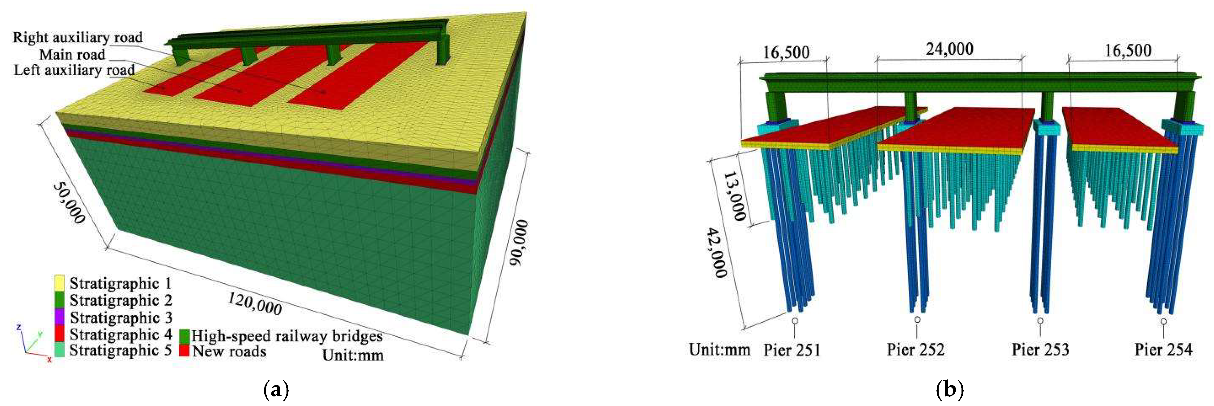
4.1. Calculation Model and Parameters Setting

A numerical simulation of the deformation caused by the construction of the new roads undercrossing pier 251 to pier 254 of the Beijing-Guangzhou high-speed railway bridge was carried out using FLAC3D finite difference software. A model was built to analyze the settlements of piers, bridge piles, and strata between the piers of the high-speed railway bridge induced by the excavation of three small spacing pits of the new roads, as shown in Figure 4. The model was set up to avoid boundary effects along the bridge with a longitudinal length of 120 m, a transverse width of 90 m, and a height of 50 m. The main road in the model is 24 m wide and the left and right side roads are 16.5 m wide. Using the cast-in-place construction, the new roads were constructed in a pile-plate u-shaped groove structure with a total length of 60 m and a thickness of 0.5 m. The foundation of the pile-plate u-shaped groove structures was made of the bored cast-in-place piles with a 0.8 m diameter with a 13 m length. The longitudinal spacing between the piles of the pile-plate u-shaped groove structure is 5 m and the lateral spacing is 4 m. Longitudinal and transverse beams with a width of 0.8 m and a height of 0.5 m were set between the piles and the pile-plate u-shaped groove structures. The roads were paved with fine to medium-grained asphalt concrete. The bridge model is a three-span simply supported bridge, with a span length of 32 m, a width of 12.6 m, and a clearance of 5.1 m underneath the bridge.
The new roads undercross the high-speed railway bridge at a low-fill section, where the new roads pass between the bridge piers of the high-speed railway, and the bases of the piers are relatively close to the edge of the new roads. It is necessary to analyze the deformation and force responses of the foundation structure of the high-speed railway bridge. The strata in the study area are widely distributed with silty soil, silty sand, and silty clay. The Mohr–Coulomb model, as a classical constitutive model of clay, can better reflect the mechanical behavior of loose or cemented soil when it enters the plastic stage. When the Mohr–Coulomb model is used in FLAC3D, the yield function of the Mohr–Coulomb model is expressed by the following:
τ σ tan φ c = 0
( σ 1 σ 3 ) ( σ 1 + σ 3 ) sin φ 2 c cos φ = 0
where σ is the normal stress on the shear plane, σ 1 and σ 3 are two principal stresses, τ is the shear stress on the shear plane, φ is the friction angle of the geotechnical material, and c is the cohesion of the geotechnical material force.
The Mohr–Coulomb model can reflect the asymmetry of the compressive and tensile strength of geotechnical materials and the sensitivity of geotechnical materials to hydrostatic pressure [35]. Meanwhile, the Mohr–Coulomb model is commonly used to describe the shear damage of soil. In addition, the parameters of the Mohr–Coulomb model can be determined by conventional tests. Therefore, for a simulation of the soil, the Mohr–Coulomb model in FLAC3D finite difference software was used in this study. For the bridge structures as well as the individual structures of the new roads, the elastic model in FLAC3D can simulate the deformation and forces of material well. In FLAC3D, the excavation of foundation pit soil can be realized by deleting the soil or assigning the soil as the NULL model. The NULL model is an empty property model that allows the material properties and entities of the component to be removed.
The 3D numerical model of the new roads undercrossing a high-speed railway bridge was created and meshed with ABAQUS software. Then, the mesh file was imported into FLAC3D and regrouped by an interface program. During grid division, the grids of foundation pit soil, the new road piles and bridge foundations, and the surrounding soil of the newly built roads were all densified according to the scope of key analysis required. After generating the mesh file with ABAQUS software, the mesh file of the computational model needed to be checked to ensure that it could work normally after being imported into FLAC3D. The material properties of the individual soil layers, road, and bridge structures were assigned by FLAC3D. The individual soil parameters in the model are set according to the ground investigation and the properties of each soil layer and the other components are shown in Table 1. The study area is characterized by a large number of soft strata, such as silt and cohesive soils, and the influence of strata elastic-plastic deformation on the numerical results needed to be taken into account in model calculations. The material properties of the remaining components are determined according to the design documentation. The main body of the bridge is composed of C50 concrete and the bridge piers and abutments are composed of C30 concrete. The piles of the bridge, the pile-plate u-shaped groove structures, and the longitudinal and transverse beams are composed of C35 concrete and the piles of the new roads are composed of C25 concrete. In FLAC3D, by grouping the soil layers, road piles, and bridge piles and setting the “Interface element” of FLAC3D at the contact interface between pile and soil, the interaction between soil and pile can be established, thus simulating the interaction relationship between soil and pile. According to the in situ tests, the shear stiffness at the contact interface between pile and soil was set at 39.8 MPa·m−1 with a friction coefficient of 0.3.

4.2. Boundary and Calculation Settings of the Model

The 3D model was set with velocity-normal and velocity-strike boundaries at the bottom in FLAC3D and no constraints were set in the model up-surface. Soil layers in the model were set as velocity-normal boundaries on all sides and the high-speed railway bridge was set with velocity-normal boundaries at both ends. Considering the influences of different soil parameters and existing bridge piers on the initial stress field, the initial stress field distribution was calculated based on the existing high-speed railway data. The model grid node displacement and velocity were cleared to zero after calculation. The excavation sequence of the model refers to the actual construction process and the simulation calculation scheme is shown in Table 2. An excavation of the foundation pits of the new roads was carried out first. Three foundation pits of the new roads are relatively close to bridge piers 252 and 253. Therefore, the disturbance to bridge piers 252 and 253 is the most obvious during construction of the new roads. The foundation pit of the main road is 60 m long and 24 m wide and the two foundation pits of the left and right auxiliary roads are of the same size, 60 m long and 16.5 m wide. All the three road pits were excavated to a depth of 1.1 m. Because the average depth of the pit was 1.1 m, it was a shallow foundation excavation. Therefore, no pit support was required. However, sloping was not allowed because of the limited space on both sides. The piles of the new roads are drilled to a depth of 13 m after the excavation of foundation pits has been completed. For simulations of the excavation of foundation pits and piles of the new roads in FLAC3D, the excavation of the soil was simulated by transferring the soil of the pits and the piles from the Mohr–Coulomb model (simulating the in situ soil in equilibrium) to the NULL model (simulating the excavation). Following the excavation of the soil of the foundation pits and piles, a filling of the road piles was carried out. The structures of the road beams were constructed after the piles were solidified and stabilized so that the road piles and the road beams could form an integral structure, which enables the road piles and the road beams to support the u-shaped plates and the pavement structure of the new roads. After completing the construction of the road beams, a pouring of the u-shaped plates of the roads and a construction of the pavement structures were conducted on the top of road beams. In FLAC3D, a numerical simulation of the construction of the new roads can be realized by further transforming the NULL model into the elastic model (simulating the construction of the structures).

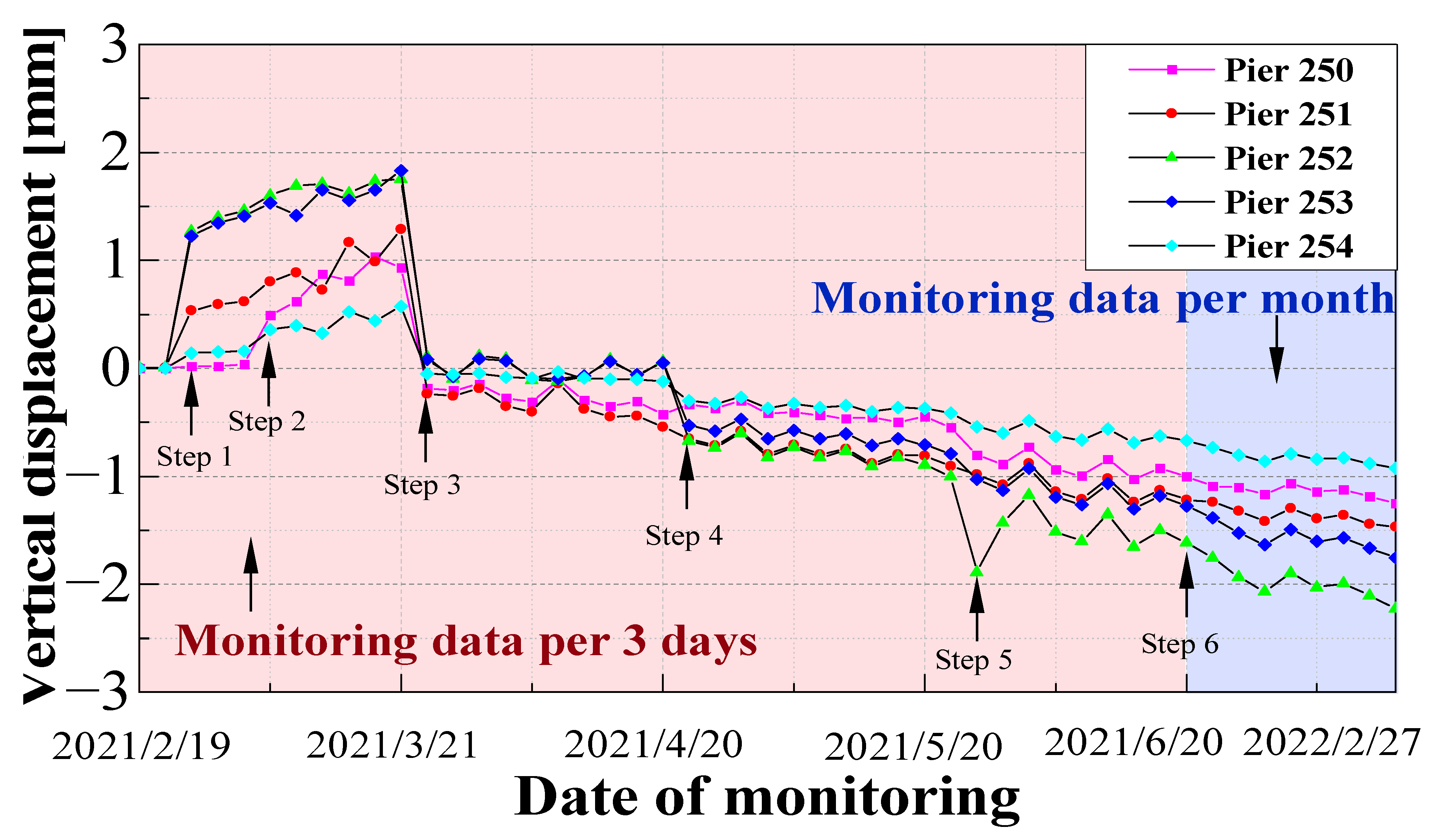
4.3. Monitoring Results and Validation of Numerical Simulation Model

Aiming at the settlement of the piers induced by the construction of a three-line small-spaced road undercrossing a high-speed railway bridge, monitoring points were arranged at the top of the piers of the high-speed railway bridge. The displacement monitoring curve of the piers is shown in Figure 5. From Figure 5, the soil around the bridge piers releases the soil pressure and a certain degree of upper displacement occurs at the bridge piers as the result of excavation of foundation pits and piles of the new roads. After the road piles are poured, the individual piers all show significant settlement. As subsequent works are carried out, various degrees of settlement occur at each pier. The construction of the new roads makes the soil around the high-speed railway bridge piers receive additional stresses greater than the original consolidation pressure, resulting in a larger settlement of the soil. The settlement of the soil causes the corresponding sinking of bridge piers. The piers 252 and 253, located between the auxiliary road and the main road, are affected by the construction of new roads on both sides, and the resultant displacement is larger than that of piers 251 and 254 on the outside of the new roads. Under different working conditions, the differential settlement between adjacent piers after construction is about 2 mm. A large differential settlement between adjacent piers can cause irregularities in the ballast track on the bridge, which seriously affects the comfort of high-speed trains and traffic safety. Therefore, in the construction of new roads undercrossing a high-speed railway bridge, attention should be paid to the differential settlement between adjacent piers and reinforcement measures for the piers that are deeply affected by the construction are desired.
To accurately reflect the displacement of bridge piers caused by the construction of a three-line small-spaced road undercrossing an existing high-speed railway bridge in the numerical simulation, displacement monitoring results of bridge piers under different working conditions are compared with the numerical simulation results of this model, as shown in Figure 6. Due to the construction of the attached facilities of the new roads between piers 250 and 251, pier 251 has a large upper displacement during the excavation of foundation pits and piles of the new roads. Comparing the two results, the displacement of piers in numerical simulation results is slightly larger than the monitoring data, which is due to the complexity of the construction on site and the simplification of the model of the new roads undercrossing a high-speed railway bridge. The results of the numerical simulation are still within a reasonable range. As shown in Figure 6, the law of bridge pier displacement shows a consistency between the numerical simulation results and the actual engineering monitoring data. Therefore, the model is able to reflect the deformation response of the foundation structure of the high-speed railway bridge induced by construction of a three-line small-spaced road undercrossing an existing high-speed railway bridge.

4.4. Ground Surface Settlement

The distribution law of soil settlement around piers caused by different construction stages of the new roads undercrossing high-speed railway bridges was analyzed according to the ground surface settlement contours of the undercrossing section of the new roads. The ground surface settlement contours under each step are shown in Figure 7. The soil excavation of foundation pits and piles in steps 1 and 2 unloads the soil around the high-speed railway piers so that the stress is redistributed. As a result, the soil in and around the foundation pits heaves and the center of the main road heaves the most. The upward displacement of piers 252 and 253, located between the roads, is more significant than the pier displacement on the outside side of the left and right auxiliary roads due to the excavation of foundation pits and piles. The amount of upward heave of the soil at the bottom of the foundation pits of the auxiliary roads is about 5–7 mm, while the amount of upward heave of the central soil at the bottom of the foundation pit of the main road can be up to 13.6 mm. In the subsequent working conditions, the filling of road piles, the pouring of road beams and u-shaped groove structures, and the paving of road surfaces caused a settlement of the soil around the newly built roads. The soil near the piers is less affected than elsewhere due to the constraining effect of foundation structures of the high-speed railway bridge on the soil.

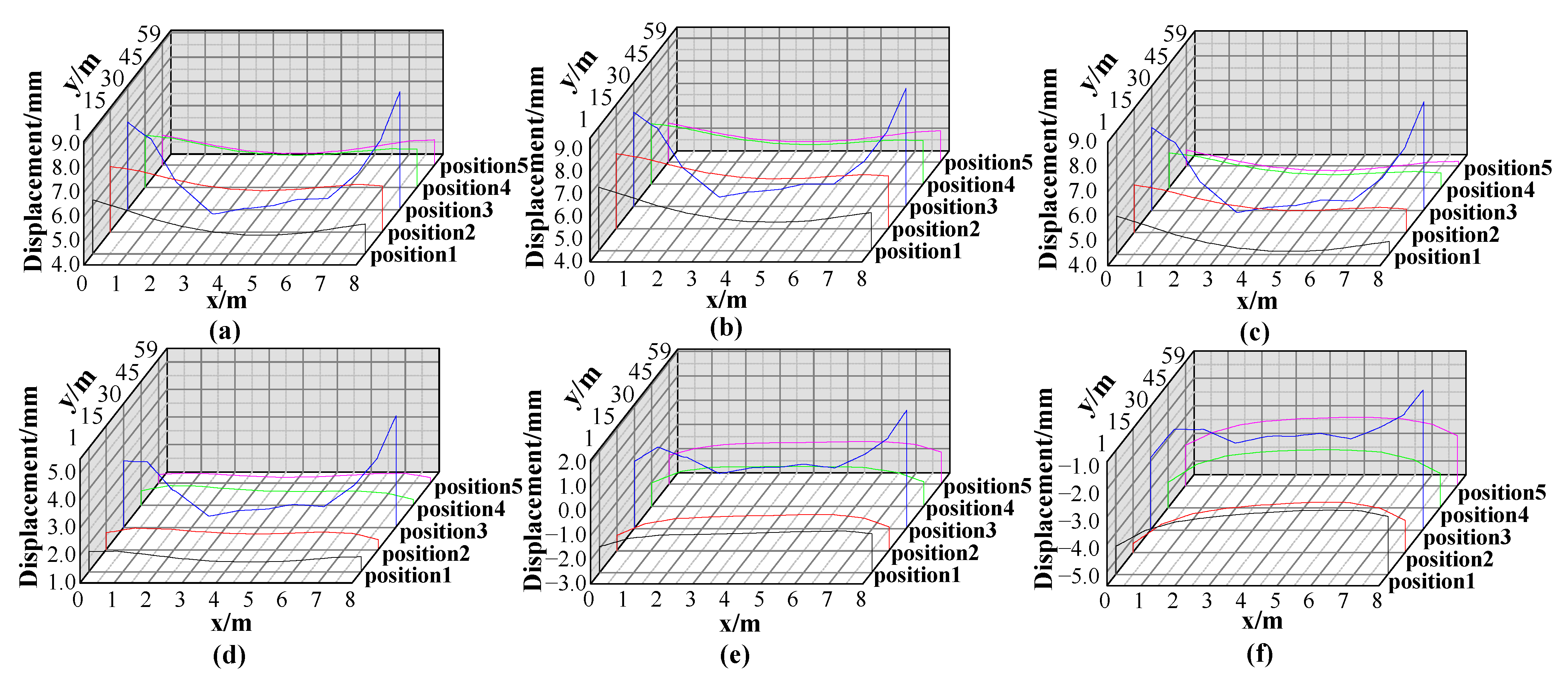
4.5. Surface Displacement of Soil Layers between Pits

The influence of new road construction on a high-speed railway bridge is mainly caused by the piers, while the small spacing excavation between multiple pits deepens the disturbance of the soil between the piers of a high-speed railway bridge. Herein, a numerical simulation of a three-line road undercrossing a high-speed railway bridge was performed to analyze the settlement of the piers of the high-speed railway bridge and their surrounding soils under various steps to determine the disturbance extent of soil layers between pits and to reflect the influence of construction of multiple roads on the high-speed railway bridge.
The project construction is relatively close to the high-speed rail piers and basic structures in the model. The closest distance between the outer side of the main road and the base of pier 252 is 0.67 m, the closest distance to the base of pier 253 is 0.64 m, and the clear spacing of the three foundation pits is approximately 8 m. The finite difference program FLAC3D was used to analyze the surface settlement of the left and right soil layers between the pits under different steps. The surface displacement of soil layers between pits are shown in Figure 8 and Figure 9. The surface displacement of the intermediate soil layers between pits is monitored at 1 m, 15 m, 30 m, 45 m, and 59 m along the longitudinal direction of the road, and the monitoring positions in the numerical simulation are shown in Figure 10. Figure 8 and Figure 9 present the surface displacement laws at different locations of the intermediate soil layers between the left auxiliary road and the main road and those between the main road and the right auxiliary road under different steps, respectively. In Figure 8 and Figure 9, the positive displacement indicates an upward heaving and the negative displacement indicates a settlement. According to Figure 8 and Figure 9, the excavation of foundation pits in Step 1 and the drilling of the piles of the new roads in Step 2 caused an overall heaving of the intermediate soil layers, with a greater amount of heaving on the surface of the intermediate soil layers close to the main road side. Subsequently, the pouring of the various structural components of the new roads led to an overall subsidence of the intermediate soil layer. In Step 3, the filling of piles caused the intermediate soil layers to sink slightly. In Steps 4 and 5, the pouring of beams and pile-plate u-shaped groove structures caused the intermediate soil layers to accelerate surface displacement. The cumulative settlement of the intermediate soil layers reached its maximum in Step 6, with the maximum cumulative settlement equal to 4.9 mm on the left and 5.2 mm on the right. In the surface displacement distribution of the intermediate soil layers under different steps, the surface settlement response of the intermediate soil layers is the most intense at 30 m along the longitudinal direction of the new roads. The surface displacement is in a groove shape, with a larger upward soil heave near the bridge piers than that at other locations. As the work progresses, the surface displacement curve in the middle of the soil layers between pits gradually rises on the side near the main road. This finding indicates that the pouring of various structures of the new roads caused the soil around the bridge piers to sink gradually and the sinking amplitude was greater than that of the soil in the middle of the humped and shaped curve. Figure 8 and Figure 9 both show that the displacement response of the intermediate soil layers close to the main road side is more obvious under each step.

4.6. Deformation Analysis of Bridge Pile

In this study, adjacent high-speed railway piers generated an uneven differential settlement during the construction of undercrossing roads, which had an effect on the structure of the high-speed railway bridge. To further analyze the disturbance effect of undercrossing road construction on the lower foundation, the horizontal and vertical displacement curves of the piles of piers 251 and 252 are plotted in Figure 11. Figure 11a,c show the vertical displacement of piles at different positions of the piers under different working conditions. The bridge piles show an overall settlement under a construction disturbance. With the excavation of the foundation pits and piles of the new roads, the piles of the bridge piers has a certain degree of upward displacement. However, with the construction of various components of the new roads, the settlement of the piles of the bridge piers also occurs. The soil excavation of the new roads causes an overall upward displacement of adjacent bridge structures and pouring of concrete structures leads to an overall settlement of adjacent bridge structures, which is consistent with the findings of Shan et al. [36] and Li et al. [37]. Figure 11b,d indicate that the horizontal displacement of piles is strongly influenced by the working conditions. According to Figure 11b,d, during the construction of the new roads undercrossing the high-speed railway bridge, different degrees of horizontal displacement occurs in the piers of the high-speed railway bridge. Due to the mutual influence of the construction on both sides [38,39,40], the construction of both the main road and the left auxiliary road balances the effect of the horizontal displacement of bridge pier 252 from opposite directions as the construction progresses. Therefore, the horizontal displacement of the pile of the bridge pier 251, where only one side is under road construction, is greater than that of the pile of the bridge pier 252, where both sides are under road construction. As construction progresses, the horizontal displacement of piles gradually accumulates and a horizontal displacement inflection point occurs at 0.2 times the pile length. The accumulated horizontal displacement increases with the pile length. The effect of undercrossing road construction on the deformation of piles of adjacent piers is manifested as an overall settlement, which is mainly manifested as a horizontal displacement at the base of piles while deflecting towards the side of the constructed roads.
To investigate the influence of new roads undercrossing the high-speed railway bridges, stress analysis is performed on the piles of piers 251 to 254 under different working conditions. The piles on the side of piers 251–254 near the road pits are chosen and the axial stress curves for the left and right sides of the piles of each pier are plotted in Figure 12. Figure 12 illustrates that the piles of piers 251 and 254, located on the outside of the left and right auxiliary roads, show consistency in the axial force characteristics. The upper part of the piles of piers 251 and 254 exhibits a compression on the side close to the foundation pit and a tension on the other side away from the foundation pit. This is because, due to the excavation of the foundation soil, the surrounding soil layer releases soil stresses and generates thrusts on the piles of piers 251 and 254, causing them to be horizontally displaced close to the foundation pit. Compared to piers 251 and 254, which have soil excavation on only one side, the soil excavation on both left and right sides has less influence on the piles of piers 252 and 253 because the construction on both sides of piers 252 and 253 balances the forces on the left and right sides of the piles to some extent. However, as the soil excavation of the foundation pit of the main road is larger than that of the foundation pits of the left and right auxiliary roads, the upper part of the piles of piers 252 and 253 produces horizontal displacements close to the foundation pit of the main road. Therefore, the upper part of the piles of piers 252 and 253 exhibits a compression on the side close to the main road pit (middle pit) and a tension on the other side close to the auxiliary road pit (left pit or right pit). As shown in Figure 12, the axial pressure of the piles of bridge piers gradually increases as construction progresses, reaching a maximum at 0.9 times the pile length, and its peak value can reach 2.8 MPa. Each pile exhibits the axial tension characteristics at shallow burial depths. This is due to the additional stress generated by the soil around the pier caused by the construction of new roads. This stress leads to a deformation in stratum and then causes the piles to generate a negative friction resistance. As the burial depth increases, the piles exhibit an axial compression. The axial pressure of piles decreases sharply when it reaches a peak value near the bottom of the piles. At this time, the force of piles is provided by the resistance of pile ends.

5. Conclusions

Engineering monitoring and numerical simulation studies were conducted on the deformation and force laws of foundation structure caused by the construction of a three-line small-spaced road undercrossing an existing high-speed railway bridge. The following main conclusions were obtained.
(1) The unloading effect caused by the excavation of foundation pits and the drilling of piles causes an overall upward heaving of the foundation structure of the existing high-speed railway bridge and the surrounding soil, and the construction of structures of the newly built roads leads to the settlement of the foundation structure of the existing high-speed railway bridge and the surrounding soil.
(2) The influence of the road construction with a larger soil excavation on the foundation structure of the existing high-speed railway bridge and the surrounding soil is more significant. The displacement response of the soil near the larger soil excavation is greater than elsewhere.
(3) As a result of the construction of multiple roads, a large differential settlement occurs between adjacent piers, and the differential settlement after construction is approximately 2 mm.
(4) The vertical and horizontal displacements of bridge piles are greatly affected by the working conditions during the construction of undercrossing roads. The deformation effect of construction of the undercrossing roads on the piles of adjacent bridge piers is manifested as the overall settlement and the horizontal displacement to the side of the soil excavation.
New multiple roads undercrossing an existing high-speed railway bridge can cause deformation and displacement of the bridge foundation structure and surrounding soil. Compared to ordinary highway projects, the pile-plate u-shaped groove structure of new roads undercrossing an existing high-speed railway bridge can reduce the disturbance of the surrounding soil caused by mass excavation of roadbed and filling compaction of roadbed. However, since the construction of undercrossing roads is close to the foundation structure of the high-speed railway bridge, it is recommended to strengthen the monitoring of the displacement of the bridge piers in the construction process to guarantee the construction safety. In addition, the operation safety of the new roads and the existing high-speed railway bridge is also worthy of attention. The interaction between the new roads and the existing high-speed railway bridge under the joint action of road vehicle loads and dynamic train loads is a appropriate focus for future research.

Author Contributions

Y.W.: conceptualization, resources, supervision, investigation, project administration; S.L.: methodology, software, writing—original draft, investigation, writing—review and editing; C.H.: data curation, writing—original draft, visualization; R.W.: conceptualization, software, writing—review and editing, supervision, project administration. All authors have read and agreed to the published version of the manuscript.

Funding

The following financial support for this research. This work was supported by NNSFC (National Natural Science Foundation of China) through project Grant Nos. 51778633, 51308552, and by 2020 Science and Technology Research and Development Plan Guiding Subjects of China Railway Corporation through project Grant Nos. 41, 243.

Institutional Review Board Statement

Not applicable.

Informed Consent Statement

Not applicable.

Data Availability Statement

Not applicable.

Acknowledgments

We would like to acknowledge the reviewers and editors for their valuable comments and suggestions.

Conflicts of Interest

We declare that we have no financial or personal relationships with other people or organizations that can inappropriately influence our work, and there is no professional or other personal interest of any nature or kind in any product, service, and/or company that could be construed as influencing the position presented in or the review of the manuscript titled, “The Foundation Settlement Response of the Existing High-speed Railway Bridge Induced by Construction of Undercrossing Roads”.

Nomenclature

Δ Empirical formula for ground settlement
d The clear distance from the edge of the pit
H The depth of pit excavation
s ( x , z ) , s ( z ) , s Equation for the lateral displacement of the free field soil
( x , z ) Any point of the free field soil outside the foundation pit
f ( ξ ) The fitted curve function of the horizontal displacement of a support pile
ξ The integral variable
LThe depth of the support pile
v Pile deflection
hsThickness of the laterally displaced soil layer
hpLength of the pile adjacent to the pit excavation
λ Relative stiffness of pile and soil
kDeformation force per unit volume of soil within each width of the pile
khHorizontal foundation reaction coefficient
EpModulus of elasticity of the adjacent pile
IpMoment of inertia of the adjacent pile
ai, bjThe constant coefficients

References

  1. Xu, K.; Li, H.M.; Lu, S.S. Study on Safety Risk Evaluation of High-Way Under-Passing Railroad. Adv. Mater. Res. 2014, 838, 1263–1267. [Google Scholar] [CrossRef]
  2. Gao, S.Q. Safety Analysis of New Highway Passing under High-speed Railway Viaduct. Railw. Stand. Des. 2015, 59, 63–67. [Google Scholar] [CrossRef]
  3. Zuo, Y.F. Research on the Influence of New Highway Under-Crossing Existing High-Speed Railway Bridge. Master’s Thesis, Beijing Jiaotong University, Beijing, China, 2016. [Google Scholar]
  4. Peck, R.B. Deep excavations and tunneling in soft ground. In Proceedings of the 7th International Conference on Soil Mechanics and Foundation Engineering, Mexico City, Mexico, 29 August 1969. [Google Scholar] [CrossRef]
  5. Caspe, M.S. Surface settlement adjacent to braced open cuts. J. Soil Mech. Found. Div. 1966, 92, 51–59. [Google Scholar] [CrossRef]
  6. Clough, G.W. Construction induced movements of in situ walls. In Proceedings of the Design and Performance of Earth Retaining Structures, New York, NY, USA, 18–21 June 1990; pp. 439–470. [Google Scholar] [CrossRef]
  7. Chen, Y.F.; Cao, M.B. The Deformation Characteristics of Soft Clay under Unloading and Reloading in Shanghai. Chin. J. Geotech. Eng. 1990, 12, 9–18. [Google Scholar] [CrossRef]
  8. Huang, M.; Liu, X.R.; Zhang, N.Y.; Shen, Q.W. Calculation of foundation pit deformation caused by deep excavation considering influence of loading and unloading. J. Cent. South Univ. 2017, 24, 2164–2171. [Google Scholar] [CrossRef]
  9. Gao, X.H.; Tian, W.P.; Zhang, Z.P. Analysis of deformation characteristics of foundation-pit excavation and circular wall. Sustainability 2020, 12, 3164. [Google Scholar] [CrossRef] [Green Version]
  10. Yi, S.; Lin, W.N.; Chen, J.; Huang, J.H.; Li, J.B.; Wu, J.M. Deformation analysis of surface and retaining wall induced by braced excavation based on random field theory. Chin. J. Rock Mech. Eng. 2021, 40, 3389–3398. [Google Scholar] [CrossRef]
  11. Liang, F.Y.; Chu, F.; Song, Z.; Li, Y.S. Centrifugal model test research on deformation behaviors of deep foundation pit adjacent to metro stations. Rock Soil Mech. 2012, 33, 657–664. [Google Scholar] [CrossRef]
  12. Xue, X.L.; Liao, H.; Zeng, C.F.; Liu, Y.S.; Zeng, X. Barrier effect of existing underground structure on strata deformation induced by foundation pit dewatering. Chin. J. Geotech. Eng. 1–9. Available online: http://kns.cnki.net/kcms/detail/32.1124.TU.20220217.1111.002.html (accessed on 19 June 2022).
  13. Luo, K.; Lei, X.Y. The Dynamic Analysis of The Existing Railway’s Subgrade Settlement Caused by Excavation Pit on Hu-Ning Line. J. Railw. Eng. Soc. 2010, 27, 5–8. [Google Scholar] [CrossRef]
  14. Yu, C. Numerical Analysis of Deep Foundation Pit Excavation Supported by Large Diameter Ring Beam. IOP Conf. Ser. Earth Environ. Sci. 2019, 242, 062033. [Google Scholar] [CrossRef]
  15. Yuan, C.F.; Hu, Z.H.; Zhu, Z.J.; Yuan, Z.; Fan, Y.X.; Guan, H.; Li, L. Numerical simulation of seepage and deformation in excavation of a deep foundation pit under water-rich fractured intrusive rock. Geofluids 2021, 2021, 6628882. [Google Scholar] [CrossRef]
  16. Bai, H.W. Study on Longitudinal Deformation of Existing Metro Tunnel Caused by Undercrossing Construction and Engineering Measures. Master’s Thesis, Beijing Jiaotong University, Beijing, China, 2008. [Google Scholar]
  17. Wang, Z.C.; Hu, Z.; Lai, J.X.; Wang, H.; Wang, K.; Zan, W. Settlement characteristics of jacked box tunneling underneath a highway embankment. J. Perform. Constr. Facil. 2019, 33, 04019005. [Google Scholar] [CrossRef]
  18. Yin, M.L.; Jiang, H.; Jiang, Y.S.; Sun, Z.Y.; Wu, Q.L. Effect of the excavation clearance of an under-crossing shield tunnel on existing shield tunnels. Tunn. Undergr. Space Technol. 2018, 78, 245–258. [Google Scholar] [CrossRef]
  19. Wei, X.J.; Zhang, M.B.; Ma, S.J.; Xia, C.; Liu, X.W.; Ding, Z. Deformation Characteristics of Existing Twin Tunnels Induced by Double Shield Undercrossing with Prereinforcement: A Case Study in Hangzhou. Adv. Civ. Eng. 2021, 2021, 7869899. [Google Scholar] [CrossRef]
  20. Liu, B.; Yu, Z.W.; Zhang, R.H.; Han, Y.H.; Wang, Z.L.; Wang, S.J. Effects of Undercrossing Tunneling on Existing Shield Tunnels. Int. J. Geomech. 2021, 21, 04021131. [Google Scholar] [CrossRef]
  21. Wang, G.F.; Wang, J.; Lu, L.H. Rules and control technology of deformation caused by shield tunnel under-passing the railway bridge culvert. J. Railw. Sci. Eng. 2016, 13, 2471–2477. [Google Scholar] [CrossRef]
  22. Wang, J.C.; Liu, X.F.; Hou, W.H. Research on the Influence of Construction of New Bridge on Foundation Displacement of High-speed Railway in Service. J. Railw. Eng. Soc. 2017, 34, 60–65, 83. [Google Scholar]
  23. Xiao, H.; Ling, X.; Lv, S. Field Test Study on Influence of Undercrossing Construction on Safety of Existing High-Speed Railway. In Proceedings of the International Symposium on Environmental Vibration and Transportation Geodynamics, Hangzhou, China, 28–30 October 2016; pp. 167–179. [Google Scholar] [CrossRef]
  24. Yang, Z.Q.; Wang, X.T. Influence of Metro tunnel excavation on deformation of existing pedestrian underpass in changzhou railway station platform. IEEE Access 2020, 8, 55860–55871. [Google Scholar] [CrossRef]
  25. Zhao, M.J.; Cheng, Y.; Song, Z.P.; Wang, T.; Zhang, Y.W.; Gong, Y.T.; Song, Y.C. Stability Analysis of TBM Tunnel Undercrossing Existing High-Speed Railway Tunnel: A Case Study from Yangtaishan Tunnel of Shenzhen Metro Line 6. Adv. Civ. Eng. 2021, 2021, 6674862. [Google Scholar] [CrossRef]
  26. Huang, Z.; Zhang, H.; Long, Z.; Qiu, W.G.; Meng, G.W.; Zhu, L.C. Field Test Optimization of Shield Tunnelling Parameters Undercrossing an Existing High-Speed Railway Tunnel: A Case Study. Geotech. Geol. Eng. 2021, 39, 1381–1398. [Google Scholar] [CrossRef]
  27. Lee, D. Analysis on the Influence and Reinforcement Effect of Adjacent Pier Structures according to the Underpass Construction. J. Korean GEO-Environ. Soc. 2022, 23, 29–39. [Google Scholar]
  28. Ding, Y.C. Excavation-Induced Deformation and Control in Soft Deposits. Ph.D. Thesis, Shanghai Jiao Tong University, Shanghai, China, 2009. [Google Scholar]
  29. Wang, C.; Yan, S.W.; Zhang, Q.B. Study of Influence of Deep Pit Excavation on Adjacent Bridge Foundation Piles. Chin. J. Rock Mech. Eng. 2010, 29, 2994–3000. [Google Scholar]
  30. Chen, L.J.; Yu, Q.F.; Dai, Z.H. 3D finite element analysis of the influence of excavation in soft soil areas in Fuzhou on the surrounding buildings. J. Railw. Sci. Eng. 2015, 12, 79–85. [Google Scholar] [CrossRef]
  31. Fan, S.Y.; Song, Z.P.; Xu, T.; Wang, K.M.; Zhang, Y.W. Tunnel deformation and stress response under the bilateral foundation pit construction: A case study. Arch. Civ. Mech. Eng. 2021, 21, 109. [Google Scholar] [CrossRef]
  32. National Railway Administration of the People’s Republic of China. Technical Specification for Highway and Municipal Engineering under Crossing High Speed Railway; China Railway Publishing House: Beijing, China, 2018. [Google Scholar]
  33. Sagaseta, C. Analysis of undraind soil deformation due to ground loss. Géotechnique 1987, 37, 301–320. [Google Scholar] [CrossRef]
  34. Zhang, A.J.; Mo, H.H.; Li, A.G.; Gao, W.; Xiang, W. Two-stage Analysis Method for Behavior of Adjacent Piles due to Foundation Pit Excavation. Chin. J. Rock Mech. Eng. 2013, 32, 2746–2750. [Google Scholar] [CrossRef]
  35. Dong, L.L. Study on Geotechnical Constitutive Models and Parameters Commonly Used in Numerical Simulation. Master’s Thesis, Qingdao Technological University, Qingdao, China, 2011. [Google Scholar]
  36. Shan, Y.; Xiao, W.X.; Xiang, K.; Wang, B.L.; Zhou, S.H. Semi-automatic construction of pile-supported subgrade adjacent to existing railway. Autom. Constr. 2022, 134, 104085. [Google Scholar] [CrossRef]
  37. Li, L.J.; Yang, H.W.; Li, Z.L.; Cai, Y.C. Numerical Analysis of the Influence of Unsupported Excavation on Adjacent Viaduct Foundation. Chin. J. Undergr. Space Eng. 2011, 7, 1697–1701. [Google Scholar] [CrossRef]
  38. Yi, L.B.; Du, M.F.; Meng, X.Y.; Jiang, M.M. Influence of the construction of deep foundation pit of subway on foundation deformation of interchange in ultra-short distance. J. Hefei Univ. Technol. (Nat. Sci.) 2022, 45, 785–792. [Google Scholar]
  39. Liu, X.; Jiang, A.N.; Fang, Q.; Wan, Y.S.; Li, J.Y.; Guo, X.P. Spatiotemporal Deformation of Existing Pipeline Due to New Shield Tunnelling Parallel Beneath Considering Construction Process. Appl. Sci. 2022, 12, 500. [Google Scholar] [CrossRef]
  40. Shilar, F.A.; Ganachari, S.V.; Patil, V.B.; Khan, T.Y.; Javed, S.; Baig, R.U. Optimization of Alkaline Activator on the Strength Properties of Geopolymer Concrete. Polymers 2022, 14, 2434. [Google Scholar] [CrossRef] [PubMed]
Figure 1. Research framework.
Sustainability 14 08700 g001
Figure 2. The undercrossing section of the new roads.
Sustainability 14 08700 g002
Figure 3. The cross-section of new roads undercrossing an existing high-speed railway bridge.
Sustainability 14 08700 g003
Figure 4. The 3D finite difference model of new roads undercrossing an existing high-speed railway bridge. (a) The overall model; (b) the pile model.
Sustainability 14 08700 g004
Figure 5. Displacement monitoring data of the existing high-speed railway bridge piers.
Sustainability 14 08700 g005
Figure 6. Comparison of monitoring data and numerical simulation results of bridge piers’ vertical displacement: (a) monitoring data; (b) numerical simulation results.
Sustainability 14 08700 g006
Figure 7. Surface settlement contours of the construction of undercrossing roads under different steps (unit: mm): (a) Step 1; (b) Step 2; (c) Step 3; (d) Step 4; (e) Step 5; (f) Step 6.
Sustainability 14 08700 g007
Figure 8. Surface displacement of the left side soil layers between pits under different steps: (a) Step 1; (b) Step 2; (c) Step 3; (d) Step 4; (e) Step 5; (f) Step 6.
Sustainability 14 08700 g008
Figure 9. Surface displacement of the right side soil layers between pits under different steps: (a) Step 1; (b) Step 2; (c) Step 3; (d) Step 4; (e) Step 5; (f) Step 6.
Sustainability 14 08700 g009
Figure 10. Numerical simulation monitoring position of surface displacement of the soil layers between pits.
Sustainability 14 08700 g010
Figure 11. Vertical and horizontal displacement of piles of high-speed railway bridge piers under different steps. (a) piles of the pier 251; (b) piles of the pier 251; (c) piles of the pier 252; (d) piles of the pier 252.
Sustainability 14 08700 g011
Figure 12. Axial stress of piles of high-speed railway bridge piers under different steps. (a) piles of the pier 251; (b) piles of the pier 252; (c) piles of the pier 253; (d) piles of the pier 254.
Sustainability 14 08700 g012
Table 1. Stratigraphic model and component parameters.
Layer NumberTypeThickness (m)Weight (kN/m3)Poisson’s RatioBulk (MPa)Shear (MPa)Cohesion (kPa)Fric (°)
1Silty soil4180.323.3310.771020
2Silty sand2180.3536.2812.09230
3Silty clay1180.312.175.621020
4Silty sand2180.3536.2812.09230
5Medium sand5180.3561.1120.37330
BridgeC50-250.219,166.6714,375--
PierC3060250.216,666.6712,500--
Bridge baseC302.5250.216,666.6712,500--
Pile of the bridgeC3542250.217,50013,125--
Pavement of the new roadsAsphalt concrete0.3524.50.351666.67555.56--
The u-shaped groove structureC350.5250.217,50013,125--
Beam of the new roadsC350.5250.217,50013,125--
Pile of the new roadsC2513250.215,555.5611,666.67--
Table 2. Simulation program.
Serial NumberConstruction SequenceStep
1Excavation of the road foundation pitsStep 1
2Drilling of the road pilesStep 2
3Grouting of the road pilesStep 3
4Pouring of the road beamsStep 4
5Pouring of the u-shaped platesStep 5
6Paving of the road surfacesStep 6
Publisher’s Note: MDPI stays neutral with regard to jurisdictional claims in published maps and institutional affiliations.

