Article

Study on Fire Ventilation Control of Subway Tunnel: A Case Study for Dalian Subway

1
School of Traffic and Transportation Engineering, Dalian Jiaotong University, Dalian 116028, China
2
College of Safety Science and Engineering, Xi’an University of Science and Technology, Xi’an 710054, China
*
Author to whom correspondence should be addressed.
Sustainability 2022, 14(14), 8695; https://doi.org/10.3390/su14148695
Submission received: 9 April 2022 / Revised: 17 June 2022 / Accepted: 12 July 2022 / Published: 15 July 2022

Abstract

:
During the actual operation of a subway company, only one ventilation-control scheme is considered in the emergency plan, without considering the specific location difference of the fire source. However, in the case of an actual tunnel fire, the best ventilation-control scheme and personnel-evacuation scheme are very different given the potential different locations of the fire source. We consider the use of a connecting channel for smoke exhaust or personnel evacuation and study the best ventilation-control scheme and personnel-evacuation scheme, when the fire source is at different positions relative to the train, and the train is at different positions relative to the connecting channel. Taking the tunnel between Yaojia Station and Nanguanling Station of Metro Line 1 in Dalian, China, as an example, a 1:1 full-scale numerical model is established to study dangerous fire-related conditions, such as carbon monoxide concentration, smoke visibility, and temperature. Nine typical working conditions of a tunnel-section fire are studied. The traditional and commonly used longitudinal-ventilation mode can ensure smoke control and personnel evacuation. For the working conditions of fire in the end of the train the ventilation-control scheme designed in this paper can ensure the safety of personnel. However, the working conditions of fire in the middle of a train are the most dangerous, and about 50% of personnel are affected by smoke during the escape. This paper analyzes the impact of the longitudinal-ventilation mode, transverse-ventilation mode, and semi-transverse-ventilation mode on personnel evacuation under such working conditions. It is found that with the semi-transverse-ventilation mode, personnel are least affected. Furthermore, semi-transverse ventilation requires a higher engineering investment, which is more than RMB 2000 per meter of tunnel. If the economic conditions are available, it is recommended to consider the semi-transverse-ventilation mode instead of the longitudinal-ventilation mode. The research results can provide guidance for the emergency-control scheme for subway-tunnel fire operation.

1. Introduction

In the case of fire in a tunnel between two subway stations, the evacuation mode specified in the Code for Design of Metro (GB 50157-2013) [1] is that the drivers should try to drive the train out of the tunnel to the station in front, and the ventilation mode should be operated according to the platform-fire mode. Only when the train is forced to stop in the section tunnel will the ventilation mode be operated according to the tunnel-section fire mode. In a long and narrow tunnel, when a train with fire cannot be driven to the station due to mechanical failure or other reasons, passengers will have a psychological panic [2]. When passengers have a psychological panic, emergency measures are not timely, or emergency facilities are not perfect, passengers may not be able to escape safely. In this case, the fans at both ends of the tunnel section are required to start, to make smoke discharge at the end close to the fire source and to make fresh air enter at the end away from the fire source, so personnel can escape safely in the direction of the fresh air [3]. However, the subway-tunnel section is narrow and long with small space and poor ventilation conditions. In the case of fire in the tunnel section, smoke spreads rapidly. In the absence of ventilation and smoke-exhaust facilities, smoke will soon spread to the whole tunnel. It is not conducive for the safe evacuation of passengers and the smooth development of fire-rescue work [4,5]. When fire occurs in the subway, only certain environmental conditions can be met for a safe evacuation. The safety factors of evacuation mainly include various combustion products and other environmental parameters caused by combustion. Countries around the world have special standards and specifications [6]. The International Building Code [7] stipulates that the bottom-surface height of the flue gas should be kept at least six feet above the height of the human-walking surface. Countries mainly consider the emergency-treatment mode of subway fire and environmental parameters such as CO concentration and air oxygen content. However, countries are different in the structure and operation mode of subway buildings, so local technical standards should be selected as often as possible. Countries mainly consider emergency-treatment methods in case of a subway fire and environmental parameters including CO concentration, air oxygen content, and so on. However, different countries have different subway building structures and operation modes, so we should choose appropriate local technical standards as a reference as often as possible.
The most reasonable evacuation method is to ensure the separation of people and smoke, to apply smoke-exhaust-ventilation facilities to discharge the smoke out of the tunnel and to let personnel move in the opposite direction of the smoke. That is, the longitudinal-ventilation mode is adopted, which makes a positive-pressure air supply face the passenger evacuation direction and makes smoke discharge against the passenger-evacuation direction [8]. However, due to the complexity of fire occurrence and the different location of the fire source and distance from the platform, there are many different fire conditions. In reality, different ventilation and smoke-exhaust methods should be set according to the location of the fire source [9]. When the tailor head of the train is on fire, the traditional push–pull-ventilation mode can be used to ensure personnel are safe and unaffected by the smoke. In the case of fire in the middle of the train, due to the long section of tunnel, personnel are far away from the station [10], and the push–pull-longitudinal-ventilation mode will submerge some people in smoke, making it difficult to ensure the safe evacuation of these people. Therefore, the reasonable setting of the ventilation and smoke-exhaust modes, when the middle of the train in the tunnel section is on fire, is a problem worthy of further study.
In the subway-tunnel section, reasonable evacuation routes are generally set, such as double tunnels, transverse connecting-channel mode, special-service channel mode, shaft-evacuation-staircase mode, etc. Most subway-tunnel sections are equipped with connecting channels. The Code for Design of Metro (GB 50157-2013) clearly points out that if the continuous length of the tunnel is greater than 600 m, a connecting channel shall be set between two single-track tunnels, and two fire doors with two-way openings should be set at both ends of the connecting channel. When there is a fire in the tunnel section, it is very necessary to effectively use the connecting channel for evacuation or smoke exhaust, according to the different positions of the train relative to the connecting channel, so as to minimize the impact of smoke on personnel. Connecting channels are usually set in subway tunnels in China and other countries. In China and other countries, for a subway with vertical ventilation, the emergency plan only considers fire at the end of the train. For fire in the middle of the train, it is considered according to fire at the end. However, in fact, fire in the middle of the train is a very dangerous situation, which needs to be analyze regarding whether the measures taken by the plan are feasible. This paper focuses on fire in the middle of a train, analyzes the safety of longitudinal ventilation, and studies the reasonable measures.
In recent years, many scholars have studied subway-tunnel fire from two aspects: physical experiment and numerical simulation. Britain, Switzerland, and other European countries gradually carried out large-scale tunnel-fire experiments in the 20th century to study the relationship between temperature and fire-source combustion time under the different working conditions of the fire load and ventilation mode and the influence of fire-combustion law on personnel evacuation. Bettis et al. [11,12] conducted a full-scale fire experiment in a mine tunnel. The research shows that the critical wind speed is directly proportional to the power of 1/3 of the heat-release rate. It is only applicable to the case of a low heat-release rate and is not applicable to the case of a high heat-release rate. Art Bendelius [13] conducted a fire test in a tunnel to verify whether there is a deviation between the empirical formula for calculating the critical wind speed and the actual results. The research results show that the deviation is less than 5% when the fire heat-release rate is under 10 MW. However, when the heat-release rate is relatively large, the calculated value of the empirical formula of the critical wind speed is 5–15% higher than the experimental value. Wu and Bakar [14] made a comparative analysis of tunnel-fire tests and numerical simulations. Taking the diameter and length of the tunnel section as the characteristic size, they obtained another formula for calculating the critical wind speed. Another factor affecting the critical wind speed is the width of the tunnel section. Kurioka [15] conducted experiments in full-scale and scale-model tunnels to study the influence of different section shapes on fire temperature. The results show that the error between the simulation data of the scale experiment and that of the full-scale experiment is very small, at below 5%. Although the field-research results have a relatively high reliability and great reference value for practical engineering, there are also many disadvantages to the physical experiment. For example, due to the complexity of subway-tunnel fire, the test cost is high and the cycle is long. Usually, a subway-fire experiment costs more than RMB 150,000, and the experiment time is more than one week. Although an indoor experiment can compare the advantages and disadvantages of various schemes, when there are many schemes, the workload of the experiment is also quite large. Due to the different actual working conditions of the subway, it is difficult to accurately reflect the accuracy of the results.
With the development of information technology, the advantages of computer simulation appear. The cost is low, the speed is fast, and the calculation results are easy to deal with. The calculation of a working condition can obtain detailed calculation data, has little deviation from the theoretical calculation, and makes it easy to limit some conditions to obtain ideal analysis results. The method of computer numerical simulation has been more and more widely used. At present, fire calculation and simulation software is more mature and has been applied in the research of subway fires. For example, there are more than 70 fire models such as CFAST, First, FDS, and Phoenix. According to the different divisions of control bodies in the study area, these models are divided into the network model, zone model, field model, and empirical model. The application of these models can predict the changes in visibility, smoke-layer height, temperature, and typical combustion-component concentration with time after a building fire and can also intuitively display the changes in dynamic temperature, visibility, and other indicators. These data can be used in the fire-safety design of buildings, personnel-evacuation analysis, safety analysis of fire-fighting facilities, and other aspects and can also provide necessary parameters for other safety-analysis methods. Mc Grattan [16] calculated and analyzed a fire in the Howard Street Tunnel by using FDS software and verified the cause of the fire and the harm caused by it. Bari [17] simulated the actual situation of a tunnel fire through fluent, analyzed, and predicted the changes in flue-gas concentration and temperature field with the time in the tunnel during a fire. Chow [18] simulated a tunnel fire through PHOENICS software, studied the relationship between the longitudinal ventilation, smoke-exhaust volume, and fire heat-release rate, and deduced the changing relationship between the three with time.
In these studies, people gradually found that the FDS (Fire Dynamics Simulator) software developed by the National Institute of Standards and Technology (NIST) is more suitable for simulating fire scenarios with thermal drive and low-speed airflow and has attracted wide attention to [19] in recent years. It solves the continuity equation, mass equation, momentum equation, and energy equation by the basic control equation, and obtains the distribution changes of fire-related physical quantities such as temperature, gas speed, and gas concentration. Currently, many scholars use FDS software to simulate subway fires. Jiang used the same height and cross-section geometry of the tunnel model for different scale fire experiments, understanding that the critical wind speed varies with the shape of the section and that under a low heat-release rate, the critical wind speed varies with a third of the power, while under a high heat-release rate, the critical wind speed and fire heat-release rate [20]. Li et al. studied the critical wind speed and flue-gas upstream length of a tunnel fire. The experimental data showed that the ratio of vertical-ventilation speed and critical wind speed and the upstream length of irrational flue gas showed an exponential relationship [21]. Lee et al. completed experiments and numerical simulations of FDS, and verified that FDS could predict the flue-gas upstream-current length and critical wind speed well [22]. Weng used the dimension-analysis method and computer simulation to derive the prediction model of the countercurrent length and critical wind speed of subway interval-tunnel-fire smoke, and pointed out that the critical wind speed predicted by the existing prediction model is small [23]. Chen et al. used CFD software to study the change relationship between critical wind speed and fire-source heat-release rate in a circular-shield tunnel section equipped with a lateral-evacuation platform [24]. Heidarinejad et al. used an experiment to study a fire-dynamics simulation and analyze the influence of fire-source location and tunnel size on the critical wind speed of a highway tunnel [25]. Starting from thermal physics, Xu Zhisheng et al. established a theoretical model of critical wind speed to control the horizontal-tunnel-fire flue gas and determined the pending coefficient in the model through the scaling-model experiment and numerical simulation, pointing out that the model is not suitable for predicting the critical wind speed [26] under the wide-ranging conditions of fire-source power. A large number of indoor and field experiments confirmed the feasibility of FDS software for subway flue-gas-control research. Therefore, we used FDS software (fire dynamic simulator) for the simulation study.
Most of the existing studies are about fire on the platform floor and the station-hall floor. For a subway-tunnel fire, most studies focus on the fire-smoke spread and the safe evacuation of personnel from the single tunnel, considering the important role of the connecting channel in the process of smoke diffusion and personnel evacuation less. In view of this, it is proposed to build a full-scale model of a subway tunnel and determine the optimal smoke-exhaust mode and personnel-evacuation direction through the analysis of CO concentration, visibility, and temperature near the ceiling, in the case of a subway-tunnel fire under different fire-source locations (relative to the connecting channel), so as to provide a reference for the preparation of a tunnel-fire-accident emergency plan for the subway-operation section. This paper studies the subway using the vertical-ventilation mode in the interval tunnel, analyzes the safe-escape situation of passengers when the fire source is located in different positions in the interval tunnel, and analyzes the reasonable solutions.

2. Theoretical Model

2.1. Basic Governing Equation

According to the mixing characteristics of gas fuel, combustion products, and gas turbulence around the combustion during a subway-tunnel fire, the large eddy-current model is adopted, and the basic control equations are shown as follows [27].
Mass conservation equation:
ρ t + ρ u = 0
where ρ is density, kg∙m−3; t is time, s; u is velocity vector, m/s; and ∇ is Laplace operator.
Component conservation equation:
t ( ρ Y i ) + ( ρ Y i u ) = ( ρ D i Y i ) + m i
where Yi represents the mass fraction of the i component; Di represents the diffusion coefficient of the i component, m2/s; and mi represents the mass-generation rate of the second component per unit volume, kg·m−3·s−1.
Momentum conservation equation:
ρ [ u t + ( u ) u + p ] = [ ρ g + f + τ ]
where p is the pressure, Pa; g is the free-fall acceleration, m/s2; f is the externally applied force vector, N; and τ is the viscous force tensor, N.
Energy conservation equation
t ( ρ h ) + ( ρ h u ) = p t + u p q r + ( k T ) + i ( h i ρ D i Y i )
where h is specific enthalpy, J kg 1 ; q r is radiation flux, W/m2; k is thermal conductivity, W m 1 k 1 ; and T is temperature, K.
Ideal gas equation of state [28,29]:
p 0 = ρ T R i Y i M i
where R is the gas constant, J mol 1 k 1 ; and Mi is the molar mass of the component, kg/mol.

2.2. Mechanical Smoke-Exhaust-Control Equation

When the flue-gas layer is stable, there are
m ˙ e = ρ g V e
m ˙ p = f ( Q ˙ C ,   D f )
where m ˙ e is the mass flow of mechanical smoke exhaust, kg/s; ρ g is the flue-gas density; and V e is the volume flow of smoke exhaust, m3/s.
Designers can estimate the amount of smoke exhaust required by the smoke-exhaust system to prevent the smoke from being reduced to a safe height within the safe-evacuation time. The general safety height is calculated by the following formula
H c = 1.6 + 0.1   H
where H is the building height.

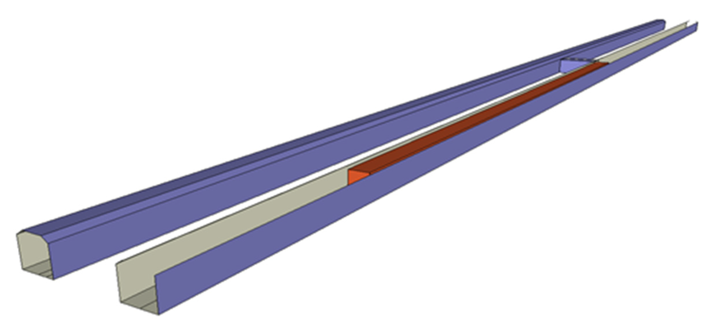
3. Model Construction

3.1. Fire-Growth Model

Since the combustion process is composed of the incubation period with slow growth at the initial stage and a subsequent significant-growth period, the model is used to describe the changing relationship of the heat-release rate with time in the firing process, and the description formula is as follows:
Q = α t 2
where Q is the heat-release rate of fire source kW, the heat-release rate is calculated according to the sum of all the train’s combustible materials, that is, considering the most dangerous state; α is the fire-growth coefficient, kW/s2; and t is the fire-development time, s. The fire-growth coefficient α can be taken at 0.002931 for a slow fire, 0.01127 for a medium-speed fire, 0.04689 for a fast fire, or 0.1878 for a super-fast fire [30]. The fire-growth coefficient α is taken as 0.1878 from a safety perspective in this paper.

3.2. Model Parameter

Taking the tunnel section between Yaojia station and Nanguanling station of Metro Line 1 in Dalian, China, as the research object, the simulated tunnel length is 300 m. The length of the connecting channel is 5.9 m, the width is 3.5 m, and the height is 3.4 m. To study the influence of a train fire on the smoke flow and temperature distribution in the tunnel section, a subway train is set in the model. The train has a total length of 117.12 m, a width of 2.8 m, and a height of 3.8 m.
At the initial time of calculation, the air temperature of the simulated environment is set at 20 °C, while the background ambient pressure is 101,325 Pa. The tunnel-construction method is shield tunneling, and the tunnel top and tunnel wall are built of concrete-pipe sheet, so the wall material around the tunnel is set as concrete in the numerical model.

3.2.1. Determination of Simulated-Fire Scale

At present, almost all new vehicles used in a subway have greatly improved safety and environmental protection. Compared with old vehicles in the past, high-strength, fire-resistant, glass fiber-reinforced plastics (FRP), aluminum alloys, and other materials have been adopted, and almost all seats are made of FRP, which ensures the spread of fire in the subway to a certain extent. The combustible materials and released heat of the subway [31] are shown in Table 1.
It can be seen from Table 1 that when the subway is burning, the overall heat release can reach 30 MW. The average heat released from the complete combustion of each carriage can reach 5 MW. Considering the most dangerous state, the fire scale to be studied in this paper is 5 MW.

3.2.2. Determination of Simulation Duration

The Code for Design of Metro (GB 50157-2013) proposes that the width of exit stairs and safe-escape routes should ensure that all passengers and staff in the Metro can escape safely within 6 min in case of a fire during long-term peak-hour passenger flow. Therefore, the calculation time of the model is 360 s.

3.2.3. Ventilation Method and Relevant Parameters

The mechanical-ventilation and smoke-exhaust methods of the subway are usually divided into longitudinal ventilation, fully transverse ventilation, and semi-transverse ventilation. Longitudinal smoke exhaust refers to discharge smoke along the tunnel directly under the action of fans at both ends of the tunnel (smoke diffuses in a section between two air shafts). For full-transverse smoke exhaust, the smoke-exhaust system and the normal tunnel-ventilation system are used at the same time. Usually, air ducts are set to uniform smoke exhaust and uniform air supplement. The semi-horizontal mode usually sets up an air duct for uniform smoke exhaust, centralized-air supplement, or without air supplement. In the case of fire, the exhaust duct is used for uniform smoke exhaust. The ventilation of the case study in this paper is longitudinal ventilation.
The size of the coach of this case study is 19 m long, 2.8 m wide, and 3.8 m high. The train is composed of six coaches. The height of the train floor to the rail surface is 1.1 m. The subway doors are mainly electric sliding doors, with four pairs of doors on each side of the passenger room. The width and height of the passenger room doors are 1.3 m and 1.86 m. The width of the end doors is 1.83 m.
The station has four TVFs (Tunnel Ventilation Fan), which can be positive and reversed. The TVF frequency is variable. In addition, the maximum air volume is 60 m3/s. The fan pressure is 1000 Pa. The maximum power is 90 KW, and the diameter of the fan is 2.0 m. The tunnel construction is shield tunneling. The diameter of the shield machine is 6 m. The tunnel end surface area is about 27.56 square meters. In the case of a tunnel fire, longitudinal ventilation is adopted. Four fans of the station at one end of the tunnel send air, and four fans at the other end exhaust air.
According to 8.3.1 of the Standard for Fire Protection Design of Metro (GB 51298-2018) [32], the wind speed of the interval tunnel should be greater than 2 m/s and not greater than 11 m/s. In the Dalian Metro Design Report (unpublished), the design wind speed of the interval tunnel is determined to be 2.6–2.8 m/s, and this paper takes 2.6 m/s.

3.2.4. Fire-Hazard Judgment Conditions

(1)
Temperature
There is injury when the ambient temperature exposed to the human body surface reaches 45 °C; and when the temperature reaches 150 °C or higher, the fire source will cause a certain amount of heat and cause a certain degree of damage to the human body, which will lead to burns of people’s body organs. Assuming that the human body is at 65 °C, it can be greatly damaged in an instant; when it is at 120 °C, it can cause irreparable damage within 15 min; and when the temperature is higher than 140 °C, people can bear it for up to 5 min. If the outside temperature is higher than the human body temperature, it will cause problems such as rapid heartbeat and dehydration to a certain extent; and when the temperature is higher than 66 °C, it is almost impossible to breathe normally, resulting in slow evacuation [33]. Based on this, the maximum acceptable flue-gas temperature at the characteristic height of human eyes is set as 66 °C.
(2)
CO Concentration
In the case of fire, with the combustion of the fire source, a large number of toxic and harmful gases will be produced, such as CO, So, etc. Since the toxic product produced by simulating train combustion in this paper is CO, the concentration of CO is taken as one of the evaluation indexes. When the CO concentration reaches 400~500 ppm, personnel would not feel it within 1 h; when the CO concentration reaches 600~700 ppm, people will have headaches, nausea, poor breathing, and other symptoms within 1 h [34], since CO concentration (ppm) interferes with the physiological response of human health. In this paper, the safety concentration standard of carbon monoxide contained in the escape routes of passengers and staff is 250 ppm.
(3)
Visibility
The visibility of smoke is a very important index for personnel escape, which has a significant impact on the escape of passengers and staff in a specific environment. Under the condition of a good visible range, passengers and staff escape quickly. Assuming that the visible range is not high, the evacuation time required to choose the escape route will increase. When the optical density is 0.08 D/m, the visibility range is 10 m; and when the optical density is 0.2 D/m, the visibility range is 5 m. Compared with a large space, a small space needs a higher optical density [35]. In this paper, the visibility condition for a safe evacuation is that the visibility at the characteristic height of the human eye, 1.7 m from the ground in the car (i.e., 2.8 m from the rail surface), is greater than or equal to 5 M.
If the numerical value of the above parameters is not greater than that of the FDS during the simulation, it is assumed that the escape process of passengers cannot be completed. Assuming that three of the above values in the simulation results are within the above parameter range, it can be considered that the ventilation scheme meets the conditions for a safe evacuation, so personnel can escape safely.

3.2.5. Simulation Grid Division

According to the cross-section of the tunnel in this section, the physical model is established, as shown in Figure 1.
In the grid division, the larger the divided grid is, the faster the computer calculation results. If the divided grid is large, the simulation results will be not accurate, and it is difficult to reflect the real fire results. The smaller the grid division is, the more accurately the FDS model simulates the real fire data, but the longer time the calculation simulation needs, which easily leads to a computer crash. Therefore, the division of the grid is very important.
A gridding method is recommended in the FDS usage manual, with the following formula:
D * = ( Q ρ c p T g ) 2 5 .  
where D* is the fire-characteristic diameter; Q is the total heat-release rate (kW); ρ is the environmental-air density (kg/m3); cp, is the ambient-air specific heat (kJ/kg·K); T is the ambient-air temperature (K); and G is the acceleration of gravity (m/s2).
The size of the grid-size division is greatly related to the fire-feature diameter. Extensive studies show that when the FDS model grid size is d = 0.1 D* or d = 0.2 D*, the simulation results will reflect the top temperature-change trend of the interval tunnel. According to the above formula, the calculation result of D* is 2. Therefore, the basic grid size d adopted by the model in this paper is taken as 0.4. For fire-source locations, encrypt the grid appropriately: 0.2(X) × 0.2(Y) × 0.2(Y). For a position far away from the fire source, in order to improve the simulation speed, appropriately increase the grid: 0.4(X) × 0.8(Y) × 0.4(Y).
The mesh division of the model is shown in Table 2. Type 1 is for the fire situation in the middle of the train, and type 2 is for the fire situation at the head or end of the train.

3.3. Working-Condition Design

In the case of a subway-tunnel fire, the reasonable selection of the ventilation and smoke-exhaust scheme plays a vital role in the safe evacuation of people, so a reasonable ventilation mode must be designed. Considering the different positions and connecting-passage distances of the train in the case of fire, we designed nine different working conditions to explore the impact of different fire-source positions on the fire smoke-exhaust mode of the subway tunnel, as shown in Table 3. In the table, the A1 condition indicates that the fire occurred at the head of the train, and the train was forced to stop near the station in front. The A2 condition indicates that the fire occurred at the head of the train, and the train was forced to stop near the rear station. The A3 working condition means that the fire occurred at the head of the train, and the train was forced to stop near the middle of the tunnel section, that is, the connecting channel is located in the middle of the train. The B1 condition indicates that the fire occurred at the rear of the train, and the train was forced to stop near the station in front. The B2 condition indicates that the fire occurred at the rear of the train, and the train was forced to stop near the rear station. The B3 condition means that the fire occurred at the rear of the train, and the train was forced to stop near the middle of the tunnel section, that is, the connecting channel is located in the middle of the train. The C1 condition indicates that the fire occurred in the middle of the train, and the train was forced to stop near the station in front (or behind). The C2 condition indicates that the fire occurred in the middle of the train, and the train was forced to stop near the middle of the tunnel section, that is, the connecting channel is located in the middle of the train. The C3 condition means that the fire occurred in the middle of the train, and the train was forced to stop near the connecting channel, that is, the train is approaching but has not reached the connecting channel or has just passed the connecting channel.

4. Results and Analysis

The local railway company adopts the longitudinal-ventilation mode, and the design wind speed is 2.6 m/s~2.8 m/s. Therefore, the longitudinal-ventilation mode is adopted in this study, and the ventilation schemes under nine working conditions are determined, as shown in Table 4. With FDS simulation, it is found that when using the recommended control scheme, these nine working conditions can allow for the safe escape of personnel, that is, they all meet the safety conditions in 3.2.4. However, it is found that the C3 condition is the most dangerous, as half of the passengers are greatly affected by smoke. Therefore, this paper focuses on the C3 working condition and analyzes the optimal-ventilation mode and scheme under the C3 working condition.

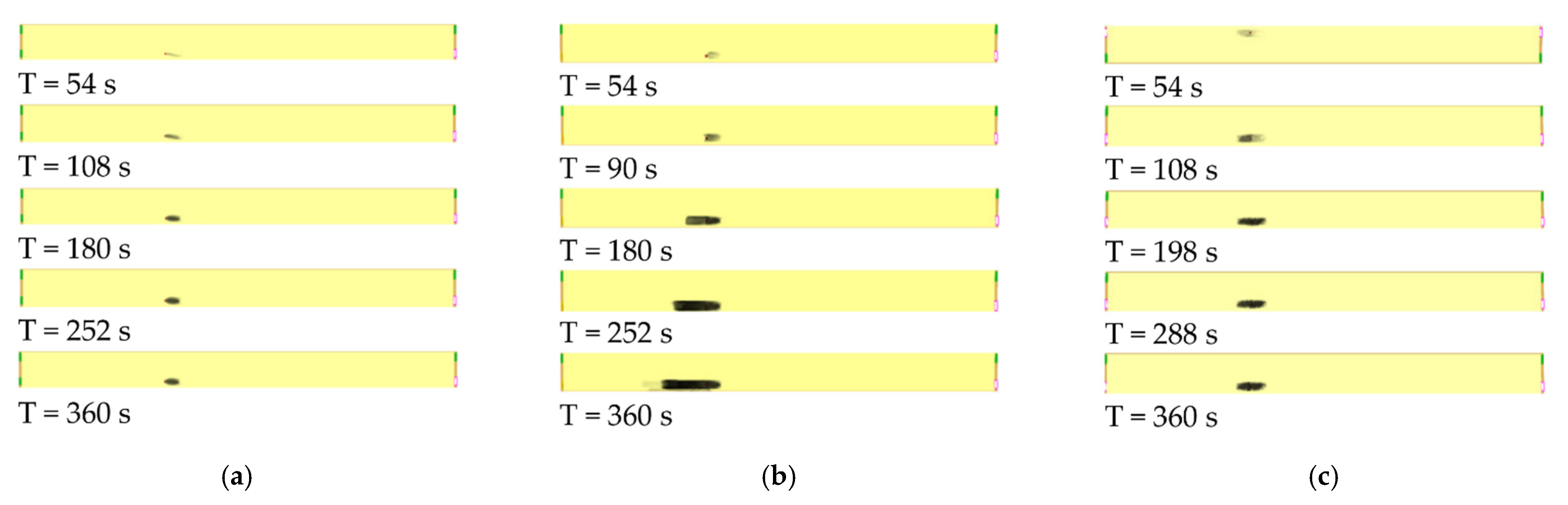
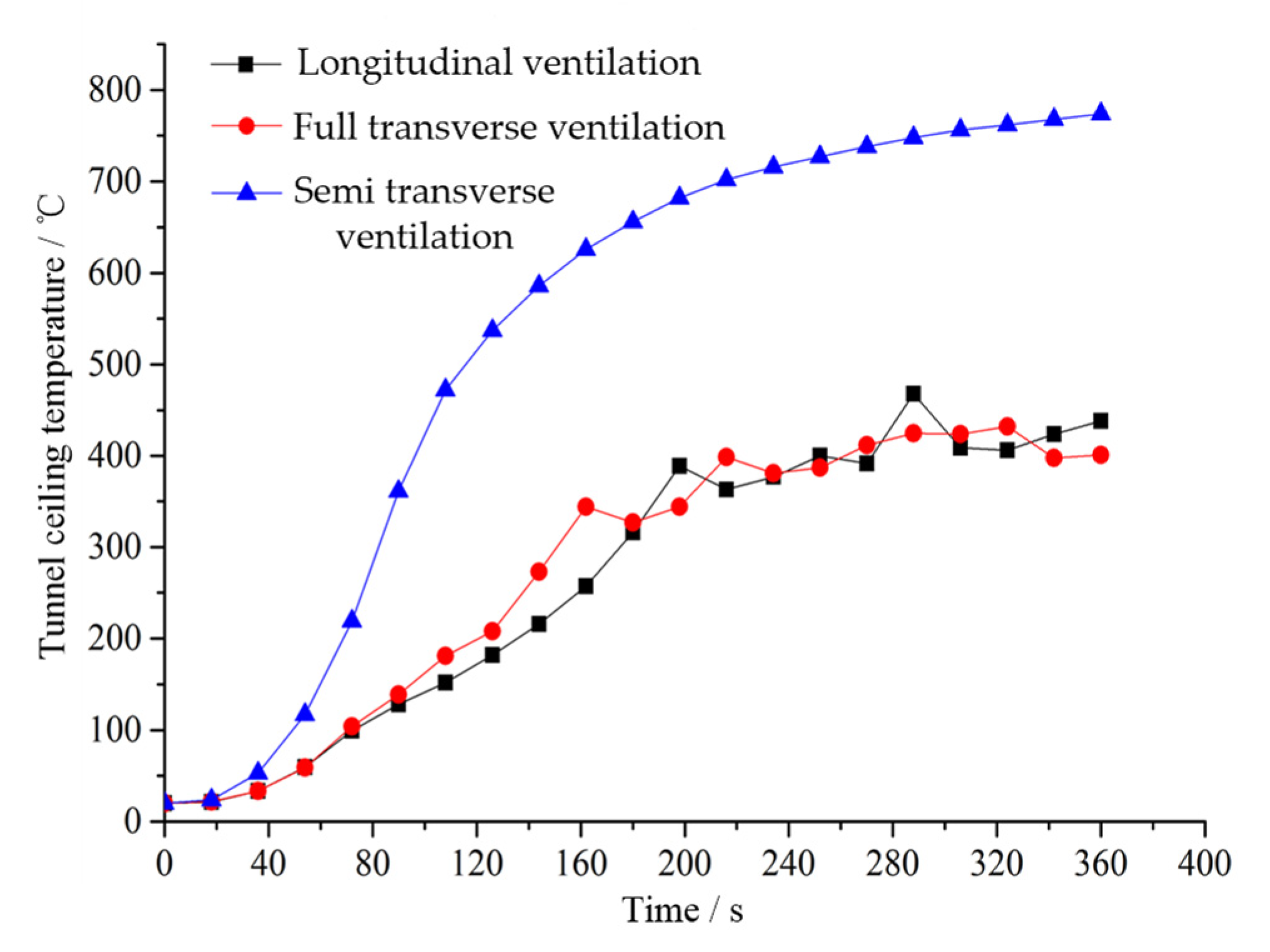
4.1. Ventilation-Mode Analysis for C3

According to the C3 working condition, the simulation analysis is carried out for three modes: full-transverse ventilation, semi-transverse ventilation, and longitudinal ventilation. The results are shown in Figure 2.
According to Figure 2, the maximum temperature of the semi-transverse-ventilation smoke-exhaust mode reaches 774 °C, the maximum temperature of the full-transverse-ventilation smoke-exhaust mode reaches 432 °C, and the maximum temperature of the longitudinal-ventilation smoke-exhaust mode reaches 438 °C. Since the flue gas of the semi-horizontal smoke-exhaust mode is only concentrated between the two exhaust outlets, the combustibles are more intense in the combustion process, and the flue gas is concentrated at the tunnel ceiling, so the temperature of the tunnel ceiling of the semi-horizontal smoke-exhaust mode is higher, while the flue gas of the longitudinal smoke-exhaust mode and the semi-transverse-ventilation smoke-exhaust mode diffuses downstream of the fire source, resulting in less flue gas accumulation at the tunnel’s top wall. The temperature is relatively low, so the average temperature in the tunnel is low as well. The fire smoke has a great impact on personnel escape. The semi-horizontal smoke-exhaust mode can control the smoke flow between the two smoke-exhaust outlets, enabling personnel to safely evacuate to both ends of the fire tunnel or non-fire tunnel, solving the problem that personnel downstream of the fire source are affected by the smoke in the longitudinal smoke-exhaust mode to a certain extent. Therefore, when the economic and technical conditions permit, the semi-transverse smoke-exhaust mode should be preferred for the smoke exhaust of the interval tunnels.

4.2. Analysis for Working Condition C3

According to the longitudinal-ventilation mode of the metro company, the ventilation scheme of working condition C3 is shown in Figure 3.
Figure 3 shows a tunnel-section fire near the connecting passage of the subway tunnel of the train. In the case of fire, some personnel will always be submerged by smoke. According to the longitudinal-ventilation mode, personnel cannot safely evacuate to the platforms at both ends. The station in front of the burning tunnel supplies fresh air at 2.6 m/s, the station behind the burning tunnel discharges smoke, and the two ends of the non-burning tunnel supply air at 1.0 m/s (the critical wind speed of the tunnel). The variation curves of the CO concentration and visibility under the two working conditions are shown in Figure 4.
Figure 4a,b show the numerical changes of CO concentration and smoke visibility at typical positions during the diffusion of smoke in a subway-tunnel section. For the fire tunnel, −10 m and +120 m at the characteristic height of the human body and the connecting channel are selected as the measuring points, because −10 m is located at the downstream of the fire source, and +120 m is taken as the measuring point upstream of the fire source due to the existence of trains. Since +120 m is located upstream of the fire source and close to the air inlet, the CO concentration is 0 and the visibility is 30 m. It is not affected by smoke, so personnel can safely evacuate upstream of the fire source. The −10 m downstream of the fire source, which is greatly affected by the flue gas, is located downstream of the flue gas. Due to the diffusion of the flue gas, the flue gas diffuses here in about 80 s, so that the visibility of the flue gas begins to decrease. Thereafter, the visibility gradually decreases with the change in time, finally reaching about 10 m and starting to maintain a stable state. The change rate of the CO concentration with time is large, reaching the maximum of 45 ppm in about 320 s. The visibility and CO concentration change slowly at the connecting channel or near the connecting channel of the fire tunnel, which are below the limit range. This is because the existence of a positive-pressure wind at both ends of the non-fire tunnel forms a certain positive pressure in the connecting channel, so the flue gas will not diffuse to the connecting channel and can only be discharged through one end of the fire tunnel. The CO concentration and visibility at the connecting passage can meet the requirements for personnel to escape safely, and personnel can escape safely through the connecting passage.
In order to comprehensively evaluate the damage degree of tunnel flue gas in a subway section at different fire-source locations to tunnel and personnel, the roof-temperature change during fire diffusion is comprehensively analyzed, and the temperature-change curve during diffusion is shown in Figure 5.
According to Figure 5a, the fire source is located at +50 m. Since the vertically developed fire plume is blocked by the horizontal ceiling, the hot flue gas will form a horizontal jet along with the ceiling, the thickness of the ceiling jet will gradually increase, and the speed will gradually decrease. The maximum temperature of the tunnel roof reaches 450 °C, which causes great damage to the top of the tunnel. The temperature-rising rate in the area close to the fire source is much faster than that in the area far away from the fire source. The time for the temperature rise to start and then reach the maximum temperature and quasi-steady-state temperature in the area far away from the fire source is later than that in the area close to the fire source. This is because it takes time for the front of the ceiling jet to reach different distances from the fire source, resulting in the “lag” of the start time of the temperature rise. The fire tunnel +30 m is located near the fire source, and the maximum temperature reaches 325 °C. It rises rapidly in the first 240 s, which also has a great impact on the tunnel ceiling. The fire tunnel +70 m is located upstream of the fire source. Since it is close to the air inlet and the temperature is a normal temperature, the flue gas has little effect on it. According to Figure 5b, the temperature of the fire tunnel changes greatly, but it is always below 45 °C, so it cannot reach the limit value of 66 °C at the characteristic height of the human body. The temperature at the connecting passage in a subway tunnel can meet the requirements for the safe escape of personnel. Therefore, under the C3 working condition, the station in front of the fire tunnel shall supply fresh air at 2.6 m/s, and the station behind the fire tunnel shall exhaust the smoke, and both ends of the non-fire tunnel shall supply air at 1.0 m/s (the critical wind speed of the tunnel). The flue gas is discharged through the rear station. Due to the positive-pressure air supply at both ends of the tunnel without fire, the positive pressure is formed in the connecting channel, and the flue gas cannot spread to the connecting channel. There is no smoke in the connecting passage of the subway tunnel, which reaches the ideal condition for personnel escape. At this time, passengers close to the upstream can escape upstream, and passengers close to the downstream can choose to evacuate safely in the contact channel.

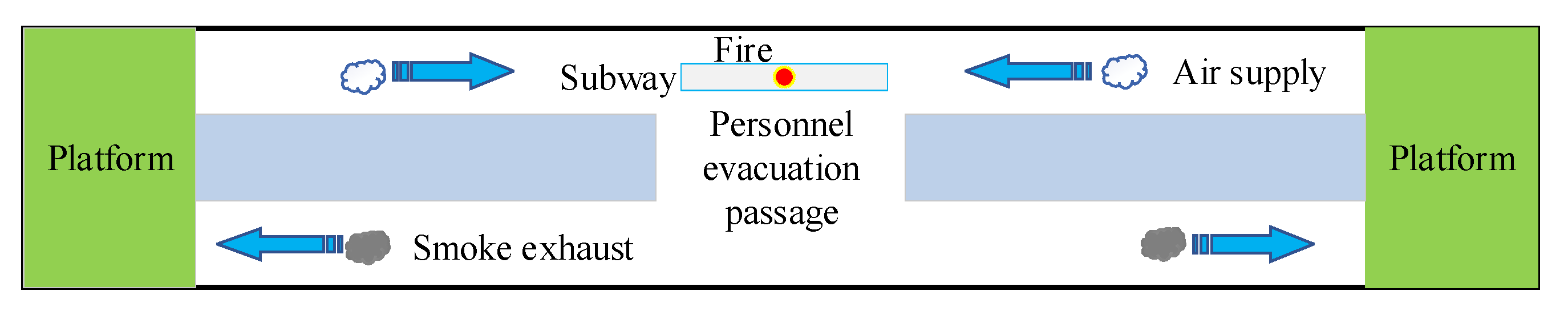
4.3. Study on Semi-Transverse-Ventilation Mode under C3 Working Condition

In the case of fire in the tunnel section where the train is close to the connecting passage, some personnel will always be submerged by smoke. In the process of escaping to the connecting passage, although passengers close to the downstream of the fire source can be safely evacuated under the C3condition, they will be affected by the smoke. To solve this problem, according to the size of the longitudinal-ventilation wind speed and the position of the smoke-exhaust outlet, a semi-transverse smoke-exhaust mode is added on the basis of C3 to study the flow characteristics and temperature-distribution characteristics of smoke in the interval tunnel. The specific working conditions are shown in Table 5.
For the semi-transverse smoke-exhaust system in Table 5, a smoke-exhaust duct is added on the basis of longitudinal smoke exhaust, and an electric smoke-exhaust outlet is set on the duct. The electric smoke-exhaust vents are in groups of two, which are closed under normal conditions. In the case of fire, the two smoke-exhaust vents are opened that were nearest to the fire source, to exhaust the smoke. According to the Code for Design of Subway (GB 50157-2013), the smoke-exhaust volume of an interval-tunnel fire shall be calculated according to the smoke-exhaust speed of a single tunnel section, which is not less than 2 m/s, but the smoke-exhaust speed shall not be greater than 11 m/s. When a tunnel fire occurs in the middle of the tunnel, it is carried out according to the axisymmetric-plume model (NFPA92B). When a 7.5 MW fire occurs in a railway tunnel, all the smoke generated by the fire shall be discharged, and the minimum smoke-exhaust volume required shall be equal to the smoke-production rate of 36 m3/s. Therefore, the smoke-exhaust volume of each smoke-exhaust outlet in a group shall be 18 m3/s, and the size of the smoke-exhaust outlet shall be 2 m × 2 m. The smoke-exhaust wind speed is 4.5 m/s, and the nearest smoke-exhaust outlet to the fire source is 10 m/s away from the fire source. When a semi-transverse smoke-exhaust system is added in the tunnel, considering the smoke-spreading process, the maximum wind speed of the longitudinal air inlet is 2 m/s. The simulation results are shown in Figure 6.
According to Figure 6a, compared with the simple longitudinal smoke exhaust, the spread distance of the smoke is significantly shortened, and the smoke is controlled between the smoke outlet and the fire source. There is basically no smoke upstream and downstream of the fire source, and the connecting channel and the tunnel are without fire, which is very safe for the safe evacuation of passengers downstream of the fire source. The flue gas reaches a stable state in about 180 s. Since the flue gas only exists between the two exhaust ports, and there is no flue gas in any other locations, the CO concentration and flue-gas visibility do not need to be considered. Personnel can safely escape to both ends of the burning tunnel and the non-burning tunnel. The flue-gas-diffusion results of condition C32 and condition C31 are roughly the same.
According to Figure 6b, compared with C31, the smoke-propagation distance increases significantly. After 90 s, the smoke begins to diffuse upstream of the fire source, because the longitudinal wind speed in the interval tunnel is less than the critical wind speed. With the combustion of the fire source, the increase in smoke concentration, and the accumulation effect of smoke, the transverse smoke outlet downstream of the fire source cannot meet the needs of the smoke diffusion, so it begins to diffuse upstream of the fire source. The flue gas downstream of the fire source is controlled between the smoke outlet and the fire source, due to the existence of the transverse smoke outlet, and the flue gas is concentrated on the top wall of the tunnel, which has little impact on personnel. The connecting channel and the unfired tunnel are basically smoke-free. However, due to the diffusion of the flue gas upstream of the fire source, and with the increase in time, the flue gas gradually accumulates in the tunnel upstream, so personnel upstream of the fire source will be affected by the smoke, which is unfavorable for their safe evacuation.
According to Figure 6c, compared with working condition C31, the smoke-spread distance increases. Since the smoke vents on both sides of the fire source are opened, the smoke is discharged through two transverse smoke vents, and the smoke spread is symmetrically distributed with the fire source as the center. Although there is no longitudinal air supply in the tunnel, compared with an air supply less than the critical wind speed in condition 13, the smoke-spread distance is significantly reduced, and the smoke is controlled between the two smoke outlets and will not spread to other parts of the tunnel. The smoke outside the smoke-exhaust outlet of the fire tunnel, the connecting passage in the subway tunnel, and the non-fire tunnel are basically smoke-free. The smoke is concentrated at the top wall of the tunnel, which has little impact on personnel. The smoke reaches a stable state around 198 s and is smoke-free at the characteristic height of human eyes, so personnel can evacuate safely.

5. Conclusions

The location of the fire source has an important impact on subway-tunnel-fire control and personnel evacuation. Through the construction of a full-scale model of the Yaojia–Nanguanling railway-station-tunnel section of Metro Line 1 in Dalian, China, nine working conditions are studied. For the most dangerous working condition, C3, a simulation is developed and the results are analyzed. The main conclusions are as follows:
(1)
When the fire source is facing a connecting passage in subway tunnel, the ventilation mode of the air supply at both ends of the fire tunnel and the smoke exhaust in connecting passage in subway tunnel is adopted. The smoke diffuses to the non-fire tunnel through the connecting passage in the subway tunnel, and the smoke can be controlled at about 10 m near the connecting passage in the subway tunnel through the platforms at both ends of the non-fire tunnel. The smoke visibility, CO concentration, and temperature at both ends of the fire tunnel meet the conditions for personnel escape, so personnel can safely escape to both ends of the burning tunnel.
(2)
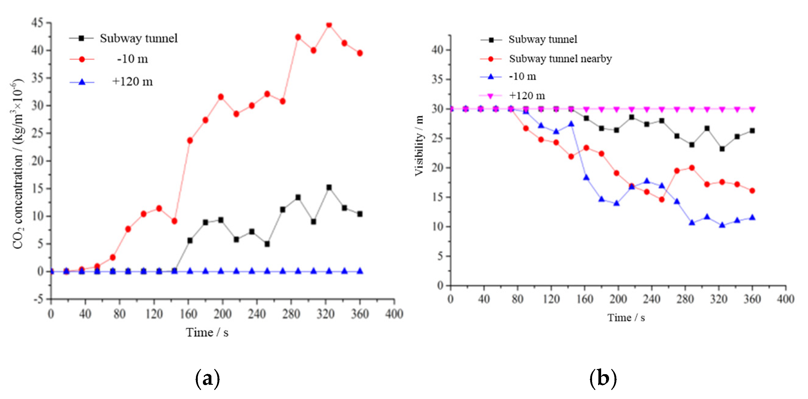
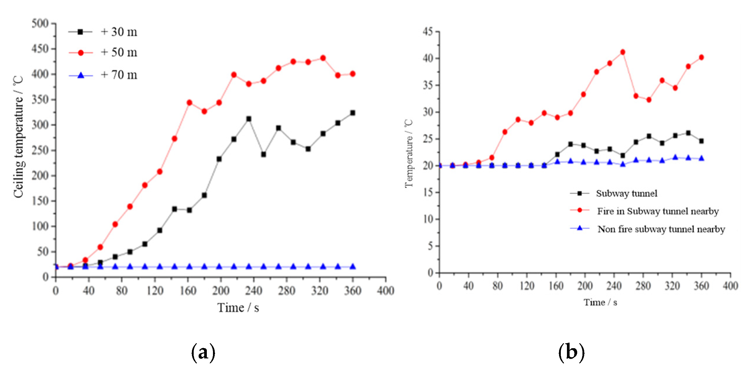
When the fire source is close to the connecting passage in the subway tunnel, the station in front of the fire tunnel shall supply fresh air at 2.6 m/s, while the station behind the fire tunnel shall exhaust the smoke. Both ends of the non-fire tunnel shall supply air at 1.0 m/s (the critical wind speed of the tunnel). The smoke is discharged through the rear station. There is no smoke in the connecting passage in the subway tunnel, which reaches the ideal condition for personnel escape. Under such working conditions, passengers close to the upstream can escape upstream, and passengers close to the downstream can choose to evacuate safely to the contact channel.
(3)
When the fire source is close to the connecting channel, the longitudinal smoke-exhaust method will be adopted, and some personnel downstream of the fire source will be submerged in the smoke. The semi-transverse smoke exhaust can solve this problem well. The effect of semi-horizontal smoke exhaust is the safest for personnel to escape safely. The smoke flow can be controlled between the two smoke-exhaust outlets, and personnel can safely evacuate to both ends of the burning tunnel or the non-burning tunnel. To a certain extent, the problem of personnel downstream of the fire source affected by smoke in the longitudinal smoke exhaust mode is solved. Therefore, when the economic and technical conditions were accepted, the semi-transverse smoke-exhaust mode should be preferred to exhaust the smoke of the interval tunnels.
(4)
Through the comparison of four different working conditions of semi-horizontal smoke exhaust, in the case of fire, with two open smoke vents near the fire source, the smoke can be controlled between the two smoke vents, and the safe personnel-escape conditions can be achieved without longitudinal ventilation. With two open smoke vents downstream from the fire source, personnel are less affected by the smoke when the longitudinal wind speed is 1.0 m/s, so the safe evacuation of personnel can be also realized.
In addition, this research is based on the typical case study of the Dalian metro. The results can be a reference for subways that apply the longitudinal-ventilation method for the interval tunnel, when the interval tunnel (contact channel to the station, or contact channel to contact channel) is long, nearly 600 m. The solutions are not applicable to subways that already use full-transverse ventilation or semi-transverse ventilation.

Author Contributions

Conceptualization, S.D. and K.W.; methodology, S.D. and K.W.; software, S.D.; validation, S.D., X.Z., and K.W.; formal analysis, X.Z.; investigation, X.Z.; resources, S.D.; data curation, S.D.; writing—original draft preparation, K.W.; writing—review and editing, K.W.; visualization, S.D.; supervision, S.D.; project administration, S.D.; funding acquisition, S.D. All authors have read and agreed to the published version of the manuscript.

Funding

This research received funding from the National Natural Science Foundation of China, grant number 51875073.

Institutional Review Board Statement

Not applicable.

Informed Consent Statement

Not applicable.

Data Availability Statement

Not applicable.

Acknowledgments

This research was financially supported by the following funds: the National Natural Science Foundation of China (51875073). The authors are also grateful to the anonymous reviewers for their constructive comments.

Conflicts of Interest

The authors declare no conflict of interest.

References

  1. GB 50157-2013; Code for Design of Metro. 2013. Available online: https://d.wanfangdata.com.cn/standard/ChxTdGFuZGFyZE5ld1MyMDIwMDkxODIwMjIwNTMwEg1HQiA1MDE1Ny0yMDEzGghwdGhlY3o5eA%3D%3D (accessed on 9 April 2022).
  2. Long, Z.; Liu, C.; Yang, Y.; Qiu, P.; Tian, X.; Zhong, M. Full-scale experimental study on fire-induced smoke movement and control in an underground double-island subway station. Tunn. Undergr. Space Technol. 2020, 103, 103508. [Google Scholar] [CrossRef]
  3. Krasyuk, A.M.; Lugin, I.V.; Alferova, E.L.; Kiyanitsa, L.A. Evaluation of ventilation flow charts for double-line subway tunnels without air chambers. J. Min. Sci. 2016, 52, 740–751. [Google Scholar] [CrossRef]
  4. Dong, S.; Wang, K.; Jia, C. A Study on the Influence of Rail Top Smoke Exhaust and Tunnel Smoke Exhaust on Subway Fire Smoke Control. Sustainability 2022, 14, 4049. [Google Scholar] [CrossRef]
  5. ATS 5387.8; Australian Technical Specification. Guidelines—Fire Safety Engineering. Part 8: Life Safety—Occupant Behaviour, Location and Condition. Standards Australia: Sydney, Australia, 2006.
  6. Zhou, D.; Hu, T.; Wang, Z.; Chen, T.; Li, X. Influence of tunnel slope on movement characteristics of thermal smoke in a moving subway train fire. Case Stud. Therm. Eng. 2021, 28, 101472. [Google Scholar] [CrossRef]
  7. International Code Council. International Building Code; International Code Council: Falls Church, VA, USA, 2000. [Google Scholar]
  8. Teodosiu, C.I.; Ilie, V.; Dumitru, R.G.; Teodosiu, R.S. Assessment of ventilation efficiency for emergency situations in subway systems by CFD modeling. In Building Simulation; Tsinghua University Press: Beijing, China, 2016; Volume 9, pp. 319–334. [Google Scholar]
  9. Helbing, D.; Farkas, I.; Vicsek, T. Simulating Dynamical Features of Escape Panic. Nature 2000, 407, 487–490. [Google Scholar] [CrossRef] [Green Version]
  10. Lambert, K.; Welch, S.; Merci, B. The use of positive pressure ventilation fans during firefighting operations in underground stations: An experimental study. Fire Technol. 2018, 54, 625–647. [Google Scholar] [CrossRef] [Green Version]
  11. Bettis, R.J.; Jagger, S.F.; Wu, Y. Interim validation of tunnel fire consequence models; summary of phase 2 tests. In The Health and Safety Laboratory Report IR/IJFR/93/11; The Health and Safety Executive: Bootle, UK, 1993. [Google Scholar]
  12. Bettis, R.J.; Jagger, S.F.; Macmillan, A.J.R.; Hambleton, R.T. Interim validation of tunnel fire consequence models; summary of phase 1 tests. In The Health and Safety Laboratory Report IR/IJFR/94/2; The Health and Safety Executive: Bootle, UK, 1994. [Google Scholar]
  13. Art Bendelius. Memorial tunnel fire ventilation test programme. In One Day Seminar of Smoke and Critical Velocity in Tunnels; Art Bendelius: London, UK, 1996. [Google Scholar]
  14. Wu, Y.; Bakar, M.Z.A. Control of smoke flow in tunnel fires using longitudinal ventilation systems—A study of critical velocity. Fire Saf. J. 2000, 35, 363–390. [Google Scholar] [CrossRef]
  15. Kurioka, H.; Oka, Y.; Satoh, H.; Sugawa, O. Fire properties in near field of square fire source with longitudinal ventilation in tunnels. Fire Saf. J. 2003, 38, 319–340. [Google Scholar] [CrossRef]
  16. Grattan, K.B.; Hamins, A. Numerical Simulation of the Howard Street Tunnel Fire, Baltimore, Maryland, July 2001; NISTIR 6902; Fire Research Division, Building and Fire Research Laboratory, National Institute of Standards and Technology: Gaithersburg, MD, USA, 2002. [Google Scholar]
  17. Bari, S.; Naser, J. Simulation of smoke from a burning vehicle and pollution levels caused by traffic jam in a road tunnel. Tunn. Undergr. Space Technol. 2005, 20, 281–290. [Google Scholar] [CrossRef]
  18. Chow, W.K. On Smoke Control for Tunnels by Longitudinal Ventilation. Tunn. Undergr. Space Technol. 1998, 13, 271–275. [Google Scholar] [CrossRef]
  19. Tavakolian, Z.; Abouali, O.; Yaghoubi, M. 3D simulations of smoke exhaust system in two types of subway station platforms. Int. J. Vent. 2021, 20, 65–81. [Google Scholar] [CrossRef]
  20. Jiang, Y.; Chen, Q. Simulation of fire temperature field and damage analysis of subway station. Struct. Eng. 2021, 37, 6–16. Available online: https://d.wanfangdata.com.cn/periodical/ChlQZXJpb2RpY2FsQ0hJTmV3UzIwMjIwMzIyEg5qZ2djczIwMjEwNDAwMhoIdWpvdGVrZWg%3D (accessed on 9 April 2022).
  21. Li, Y.Z.; Lei, B.; Ingason, H. Study of critical velocity and backlayering length in longitudinally ventilated tunnel fires. Fire Saf. J. 2010, 45, 361–370. [Google Scholar] [CrossRef]
  22. Lee, S.R.; Ryou, H.S. A numerical study on smoke movement in longitudinal ventilation tunnel fires for different aspect ratio. Build. Environ. 2006, 41, 719–725. [Google Scholar] [CrossRef]
  23. Weng, M.C.; Yu, L.X.; Liu, F. Smoke Backlayering Length and Critical Wind Velocity in a Metro Tunnel. J. South China Univ. Technol. (Nat. Sci. Ed.) 2014, 42, 121–128. [Google Scholar] [CrossRef]
  24. Chen, S.; Bi, H.Q.; Liu, X.X.; Wamg, J. Numerical Simulation Study on Critical Velocity in Subway Tunnel Fire. Refrig. Air Cond. 2017, 31, 245–248. [Google Scholar] [CrossRef]
  25. Heidarinejad, G.; Mapar, M.; Pasdarshahri, H. A comprehensive study of two fire sources in a road tunnel: Considering different arrangement of obstacles. Tunn. Undergr. Space Technol. 2016, 59, 91–99. [Google Scholar] [CrossRef]
  26. Xu, Z.S.; Zhao, H.L.; Li, H.; Jiang, X. Theoretical model of critical wind velocity in horizontal tunnel fires. J. Cent. South Univ. (Sci. Technol.) 2013, 44, 1138–1143. [Google Scholar]
  27. Chow, W.K. Simulation of Tunnel Fire Using a Zone Model. Tunn. Undergr. Space Technol. 1996, 11, 221–236. [Google Scholar] [CrossRef]
  28. Wang, K.; Pan, H.; Zhang, T.J. Experimental Study of Prefabricated Crack Propagation in Coal Briquettes under the Action of a CO2 Gas Explosion. ACS Omega 2021, 6, 24462–24472. [Google Scholar] [CrossRef]
  29. Wang, K.; Pan, H.Y.; Zhang, T.J.; Wang, H.T. Experimental study on the radial vibration characteristics of a coal briquette in each stage of its life cycle under the action of CO2 gas explosion. Fuel 2022, 320, 123922. [Google Scholar] [CrossRef]
  30. Huo, R.; Hu, Y.; Li, Y.Z. Introduction to Building Fire Safety Engineering; Press of University of Science and Technology of China: Anhui, China, 2009. [Google Scholar]
  31. Chen, F. Study on Smoke Flow and Personnel Evacuation Simulation in Subway Tunnel Fire; Chongqing University: Chongqing, China, 2010. [Google Scholar]
  32. GB 51298-2018; Standard for Fire Protection Design of Metro. 2018. Available online: https://d.wanfangdata.com.cn/standard/ChxTdGFuZGFyZE5ld1MyMDIwMDkxODIwMjIwNTMwEg1HQiA1MTI5OC0yMDE4GghtcmNyNTFydQ%3D%3D (accessed on 9 April 2022).
  33. Feng, T. Study on Fire Smoke Flow Characteristic and Control Method in Subway Tunnel; China University of Mining and Technology: Beijing, China, 2017. [Google Scholar]
  34. Zhou, J.L.; Hu, R.H. Fire hazard and escape Countermeasures. Overv. Disaster Prev. 2002, 3, 14–15. Available online: https://d.wanfangdata.com.cn/periodical/ChlQZXJpb2RpY2FsQ0hJTmV3UzIwMjIwMzIyEg5RSzIwMDIwMTI4ODkzOBoIY2Q1Mmx6djg%3D (accessed on 9 April 2022).
  35. Xu, Z.S. Smoke Control Works; China Machine Press: Beijing, China, 2011. [Google Scholar]
Figure 1. Physical-calculation model of tunnel section.
Sustainability 14 08695 g001
Figure 2. Temperature distribution at the ceiling in the tunnel under different smoke-exhaust modes.
Sustainability 14 08695 g002
Figure 3. Ventilation-design drawing of working condition C3.
Sustainability 14 08695 g003
Figure 4. Variation curves of CO concentration and smoke visibility: (a) CO concentration; (b) smoke visibility.
Sustainability 14 08695 g004
Figure 5. Temperature change curve: (a) ceiling; (b) connecting passage in subway tunnel and nearby.
Sustainability 14 08695 g005
Figure 6. Smoke spread in tunnel fire: (a) C31; (b) C33; (c) C34.
Sustainability 14 08695 g006
Table 1. Combustible materials and released heat of the subway.
NumberNameMass/
kg
Released Heat per Unit Mass/
(MJ/kg)
Total Released Heat/
(MJ)
1Seat201285629
2Window69261778
3Sound-insulation facilities919844
4Padding91262340
5Floor covering102333376
6Wall- and top-insulation material91181669
7Glass-window washer21843
8Lampshade1935687
9End cover926235
10Insulated cable4542611,703
11Battery pack926235
12Lubricating oil451184
13Control cover68261754
14Total 30,477
Table 2. Model meshing.
TypeRegionGrid Size (m)Number of X, Y, Z Grids (PCs.)Total Number of Grids (PCs.)
1(Y = −150, Y = −30)0.4 × 0.8 × 0.445 × 150 × 15101,250
(Y = −30, Y = 30)0.2 × 0.2 × 0.290 × 300 × 30810,000
(Y = 30, Y = 150)0.4 × 0.8 × 0.445 × 150 × 15101,250
2(Y = −150, Y = 30)0.4 × 0.8 × 0.445 × 225 × 15151,875
(Y = 30, Y = 70)0.2 × 0.2 × 0.290 × 200 × 30540,000
(Y = 70, Y = 150)0.4 × 0.8 × 0.445 × 100 × 1567,500
Table 3. Working conditions of different fire-source locations.
Working ConditionTrain Fire Source LocationTrain Stop Position
A1HeadClose to the station ahead
A2Close to the rear station
A3Middle of tunnel section
B1TailClose to the station ahead
B2Close to the rear station
B3Middle of tunnel section
C1Central sectionNear the front (rear) station
C2Middle of tunnel section
C3 The train stops near connecting passage in subway tunnel
Table 4. Ventilation and evacuation schemes under different working conditions.
Ventilation ModePersonnel Evacuation Plan
A1The rear station fan supplies fresh air and the front station fan discharges smokeEvacuate to the rear station or connecting passage
A2The rear station fan supplies fresh air and the front station fan discharges smokeEvacuate to the rear station
A3The rear station fan supplies fresh air and the front station fan discharges smokeEvacuate to the rear station or connecting passage
B1The front station fan supplies fresh air and the rear station fan discharges smokeEvacuate to the station ahead
B2The front station fan supplies fresh air and the rear station fan discharges smokeEvacuate to the station or connecting passage ahead
B3The front station fan supplies fresh air and the rear station fan discharges smokeEvacuate to the station or connecting passage ahead
C1The rear (front) station fan supplies fresh air, and the front (rear) station fan discharges smokePersonnel near the front (rear) station shall escape towards the station, and other personnel shall evacuate to the rear (front) station or connecting channel
C2Fresh air is supplied by fans at both ends of the fire tunnel station, and smoke is discharged at both ends of the unfired tunnelEvacuate to both ends of the burning tunnel
C3Fresh air is supplied from the station in front (rear) of the fire tunnel, smoke is discharged from the station in rear (front) of the fire tunnel, and air is supplied from both ends of the unfired tunnel
Table 5. Working conditions of C3 after adding smoke-exhaust outlet.
Working
Condition
Smoke-Exhaust Wind Speed/(m/s)Number of Smoke Vents OpenedSmoke-Exhaust Opening PositionLongitudinal-Inlet Wind Speed/(m/s)
C314.52Downstream of fire source2.0
C324.52Downstream of fire source1.0
C334.52Downstream of fire source0.5
C344.52Both sides of fire source0
Publisher’s Note: MDPI stays neutral with regard to jurisdictional claims in published maps and institutional affiliations.

