Article

Non-Destructive Testing of Pipe Conveyor Belts Using Glass-Coated Magnetic Microwires

by
Karol Semrád
and
Katarína Draganová
*
Faculty of Aeronautics, Technical University of Košice, Rampová 7, 04001 Košice, Slovakia
*
Author to whom correspondence should be addressed.
Sustainability 2022, 14(14), 8536; https://doi.org/10.3390/su14148536
Submission received: 24 June 2022 / Revised: 6 July 2022 / Accepted: 11 July 2022 / Published: 12 July 2022

Abstract

:
Belt conveyors have been used in a wide range of applications because in comparison to the alternative solutions represented by the rail or road transportation, their operation is typically more cost effective, with lower energy demands and the possibility of utilizing renewable energy sources, and during their operation, less noise and air pollution is produced. The presented article is focused on pipe belt conveyors that are even more sustainable and in harmony with the environment, especially considering transportation of fine and dusty materials. More specifically, pipe belt conveyors have the possibility of utilizing microwires as a sensing element for microwire-based sensors for the pipe belt conveyor diagnostics from a mechanical loading point of view. This is because during the enclosing of the pipe conveyor belt, periodical cyclical mechanical loading is applied due to the bending. From the results of the performed set of FEM (Finite Element Method) analyses of the glass-coated magnetic microwires, it can be concluded that during the selection process of the microwires, emphasis should be directed the thickness of the glass coating, which can affect the lifetime of the microwire significantly. The microwire length has negligible influence on the estimated number of bending cycles until the damage or crack occurs.

1. Introduction

Belt conveyors have been used in a wide range of applications. In our everyday lives, they are seen in supermarkets and at the airports where belt conveyors are used in the baggage handling systems from the check-in conveyors to the carousels ensuring the quick, effective, and reliable transport of the baggage during the whole transportation process at the airport. Belt conveyors also often solve variety of challenges in the logistical centers, where they can ensure not only transportation of goods or packages, but also sortation, loading, and unloading procedures.
Our research is focused on the industrial applications, where belt conveyors have been used for the transport of goods and raw or processed materials. In this case, belt conveyors often must cover long distances with different terrain conditions. In comparison to alternative solutions represented by rail or road transportation, the conveyor belt systems are typically more economical [1] because of their lower energy demands and possibility to use renewable energy sources [2], but from an environmental point of view [3], they typically expend less energy and less emissions of CO2 for example. Additionally, they have a reduced level of noise pollution [4].
Manufacturers must also meet various specific requirements, such as the capability of conveying hazardous materials, heavy payloads, or high temperatures. The challenging can be also the transportation of dusty materials. Therefore, in addition to the conventional open belt conveyors, closed pipe belt conveyors can present the most suitable solution. The pipe conveyor belt is based on the construction of the conventional belt conveyor, both fabric and steel reinforcing can be used, but the belt must be capable of forming a complete circle or oval with an overlap. In these systems, the transported material is transported in the closed belt, therefore the ambient dust is not present. The risk of falling material can be also eliminated in these systems. Furthermore, the utilization of the dust-free conveyor belt systems can be also a subject of the regulations, especially for example in the urban areas, where the produced pollution can be a crucial factor. Other advantage of the pipe belt conveyors is that they can be installed with smaller radii of vertical and horizontal curves and with steeper inclination angles in comparison to the conventional open belt conveyors. This is a great advantage when there are spatial restrictions for the placement of a belt conveyor system [5]. The developed innovative designs of pipe belt conveyors can even expand their application possibilities [6].
Research in the area of pipe belt conveyors is focused not only on the design concepts and their optimization for example from the pipe diameter [7] or shape stability [8] point of view, but also on the possibilities of the optimization of the energy consumption for example by the power balance of starting process of the belt conveyor [9], active speed control [10] or indentation of the rolling resistance [11,12]. For this purpose, also idlers for the measuring of the indentation rolling resistance [13] or completely new systems for example based on the permanent magnets with low resistance [14] have been developed. During the design of the conveyor belt, it is also very important to have knowledge about the tension forces [15] and their influence for example on the contact forces of the already mentioned idler rolls [16]. For the analysis of the contact forces, finite element method (FEM) models or their enhancements for example in the form of the coupled FEM and discrete element method (DEM) models [17] and many types of testing devices [18] have been developed. It is also very important to have knowledge not only about the static and lateral forces [19] or pressures [20] of the pipe belt conveyors or about their supporting roller groups [21], but also about the dynamic contact forces [22] especially considering the elastic or hyperplastic behavior of the used materials, which are bent [23] because the belt replacement, especially considering the belt conveyors used for the transportation at long distances [24], can be a very complex task. This is the reason why many inspection methods use either static inspection devices, the localization of which can be performed by applying advanced methods based for example on the deep neural networks [25] or using the inertial measurement units creating a basis for the automatic measurement of level differences in belt conveyors [26]. However, there are also many types of mobile robot-based inspection systems for the automatic inspection of the belt conveyors [27] capable of operation even in harsh outdoor environments [28]. The inspection methods often use optical methods involving vision-based [29] and thermal infrared [30,31,32,33,34] principles with the integrated warning systems [35]. Another important factor that must be considered is the control of the transportation capacity of the belt conveyors [36]. Research in the area of non-destructive testing, diagnostics, and health-monitoring systems for the belt conveyors is also a focus in the utilization of acoustic sound-based [37,38,39] and radar [40] methods. Furthermore, methods based on the magnetic sensors [41,42] and ultra-high frequency (UHF) radio frequency identification (RFID) sensors, which can be used for the crack detection [43,44], seem to be very perceptive. Cracks [45] are often caused by the dynamic impact forces, therefore their measurement and monitoring are also very important [46]. Together with the monitoring and diagnostic methods, the statistical procedures [47] for fault diagnostics and damage detection involving the algorithms based on the neural networks for example [48] have been developed. Statistical and numerical procedures and life time forecasting methods [49] can be consequently used as the basis for the planning of the maintenance procedures [50] also involving procedures for the predictive maintenance of the belt conveyor systems [51] because the reliability of the conveyor belt operation can be significantly increased not only by the utilization of suitable diagnostics and health-monitoring systems, but also by the corresponding convenient maintenance procedures, which can significantly increase operational time of the belt conveyors and their life-time, thus significantly reducing the operational costs of the belt conveyors and contributing to the development of sustainable transportation systems.
As it can be seen from the current state overview, the research in the area of the pipe belt conveyors is focused mainly on the conceptual design optimization. Diagnostic methods are usually focused on the conventional conveyor belt systems and do not involve particularities caused by the bending of the belt in the pipe belt conveyors, which are much more in harmony with the environment, especially considering the transportation of fine granular materials such as grain and cement, where dust can cause a significant pollution. Therefore, our research is focused on the utilization of the magnetic sensors using the glass-coated amorphous magnetic microwires in the role of a sensing element, for the contactless non-destructive testing, monitoring, and diagnostics of the pipe belt conveyors.
The current study is focused on the utilization possibility of the microwire embedded into the hyper elastic material of the pipe conveyor belt. Furthermore, due to the singularities of the pipe conveyor belts, where the microwire is exposed to the periodical mechanical loading during the enclosing of the pipe conveyor belt, it was necessary to perform a whole set of static analyses on the glass-coated microwires with different cores, glass-coating diameters, and lengths. The mechanical analysis results can be presented in the different forms, including the visualization of the displacement magnitudes and the stresses von Mises of the microwires. Furthermore, from the performed simulations, it is possible to estimate the expected lifetime of the microwire. This indicates if the microwire with the specific geometrical dimensions is convenient for the utilization in the applications, where the cyclic mechanical loading is expected.

2. Materials and Methods

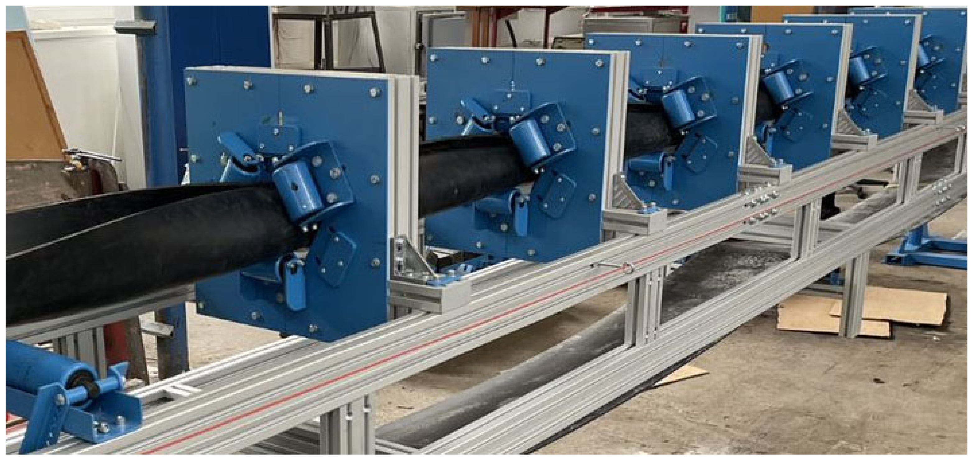
2.1. Pipe Belt Conveyor

The subject of our research is the experimental pipe conveyor belt placed at the Faculty of Mining, Ecology, Process Control and Geotechnologies of the Technical University of Košice, the part of which can be seen in Figure 1. The conveyor belt is composed of the aluminum modular systems with the dimensions of 45 × 90 mm ensuring sufficient stiffness of the structure. The whole experimental system is modular; therefore, it is possible to mount and demount the structural parts of the system, including the drum, and to place the parts into the desired positions. The drum size is 400 mm and the maximum width of the installed belt is 400 mm. The belt can be enclosed so that the diameter of the enclosed part of the conveyor belt can be changed from 80 mm up to 140 mm. In our case, a radius of 63.5 mm was used for the simulations. The distance between the two supports along the belt is 1200 mm.

2.2. Microwire

Considering the current trend of miniaturization of the sensors, magnetic microwires seem to be a very perceptive material in the sensor applications not only because of their dimensions, but also due to the manufacturing rate and productions costs. Microwires can be fabricated according to the specific needs and requirements of the customers because the composition of the magnetic microwires together with their dimensions have a significant influence on the physical and mechanical properties. Our research is focused on the amorphous glass-coated magnetic microwires consisting of a metal core with the diameter of 0.6–30 μm and the glass coating with the thickness of 2–20 μm. For this study, a magnetic microwire with a length of 20 mm, with the core diameter of 15 μm and with an overall diameter of 35 μm was used. The chemical composition of the microwire was Fe77.5Si7.5B15. These microwires in their structure involve an axial domain wall in the middle of the wire covered by the radial domains and closure domains at the ends of the microwire. This structure results into the magnetization process, which is performed through the single Barkhausen jump, when magnetizing the microwire from the positive into the negative saturation state. For the whole magnetization process, the bistable or orthogonal hysteresis loop is typical.
The functional principle of the microwire-based tensile stress sensor is based on the dependence of the applied mechanical tensile stress σ, which can be determined from the measurement of the switching field HSW of the magnetic microwire:
H S W σ A λ s σ μ 0 M S ,
where A is the exchange constant, MS is the saturation magnetization, λS is the saturation magnetostriction, and µ0 is the magnetoelastic permeability of the vacuum. During the evaluation of the applied mechanical tensile stress, not only the external mechanical tensile stress, but also the tensile stresses created as a result of the fabrication process, thermal expansion coefficients must be considered.
The measurement method is based on the enhanced induction methodology, which uses the magnetic microwire as a sensing element and the formation of the excitation and sensing coils that are placed outside of the magnetic microwire. This configuration allows the contactless measurement of the magnetic field and indirectly of the tensile stresses.
Our previous research was focused on the utilization of the magnetic microwire in the role of a sensing element of the tensile stress sensor for the non-destructive testing of composite aircraft structures [52]. In the mentioned paper, the theoretical background, the functional principle together with the whole measurement chain and the measuring methodology is described in the details.
During the measurements, the magnetic microwire was embedded directly into the technical rubber and its response to the applied mechanical stress was measured. Due to the utilization of the microwire with the chosen chemical composition, it is possible to measure not only the magnetic field [53], but also mechanical stresses, the knowledge of which is important, especially if we consider the pipe belt conveyors that are cyclically periodically mechanically loaded, and therefore to achieve sustainable operation of these type of conveyor belts it is even more important to monitor the wear and potential damages of the belt to ensure continuous and sustainable operation of the pipe belt conveyor. For the application of the microwire as the sensitive part of the sensor, in addition to the response to the external physical quantities, the microwire noise characteristics [54] are a determining factor.

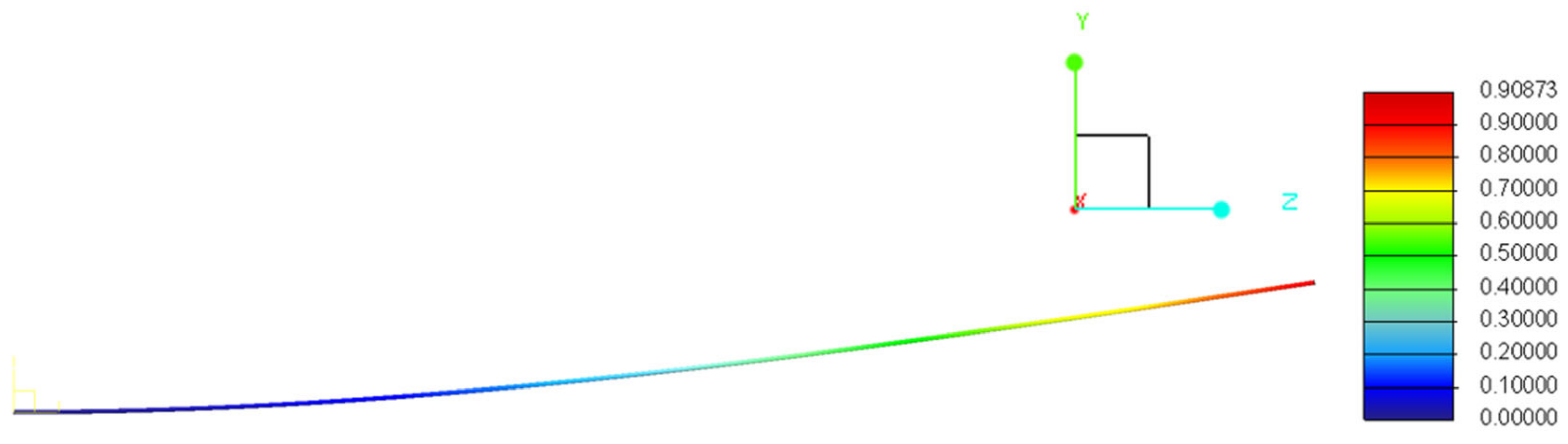
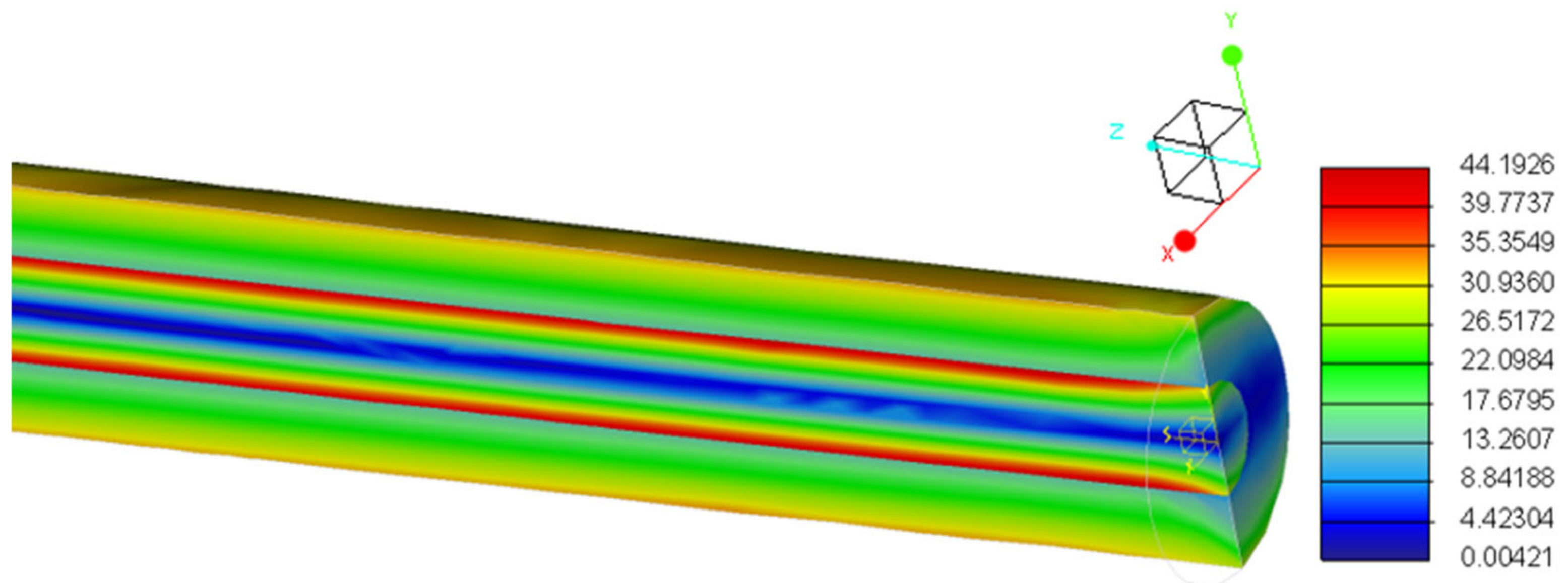
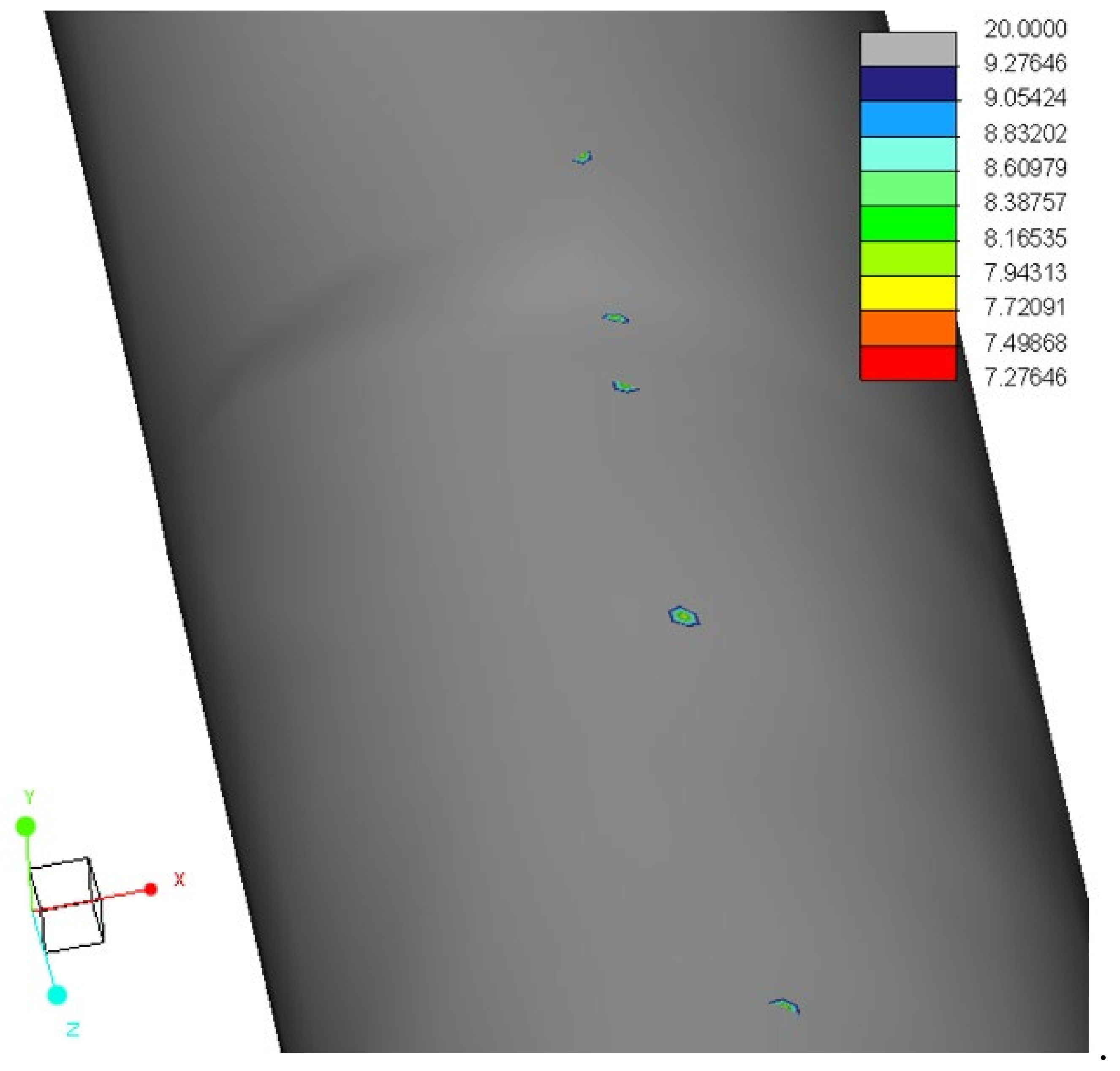
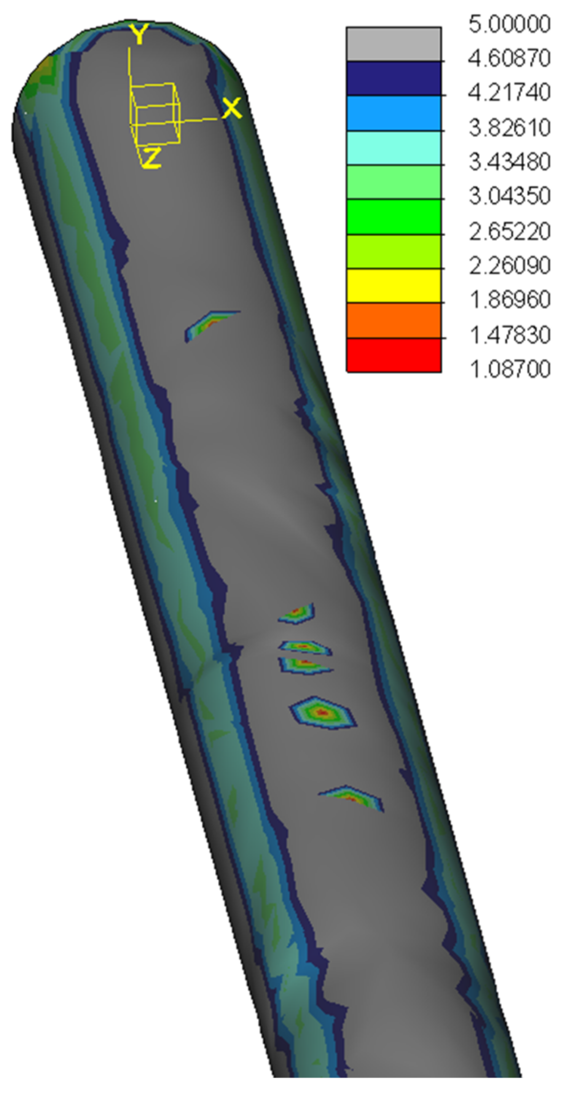
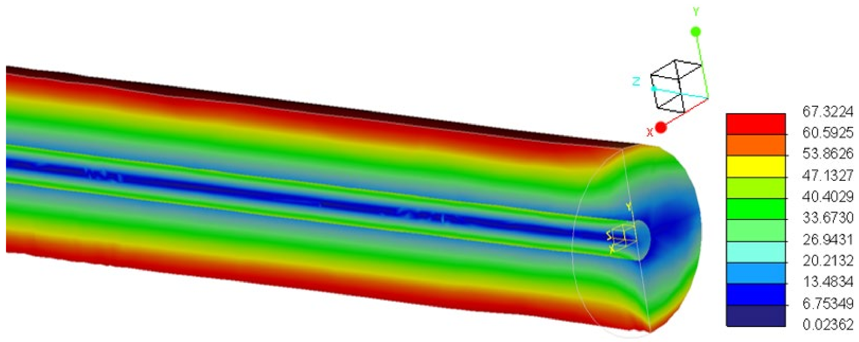
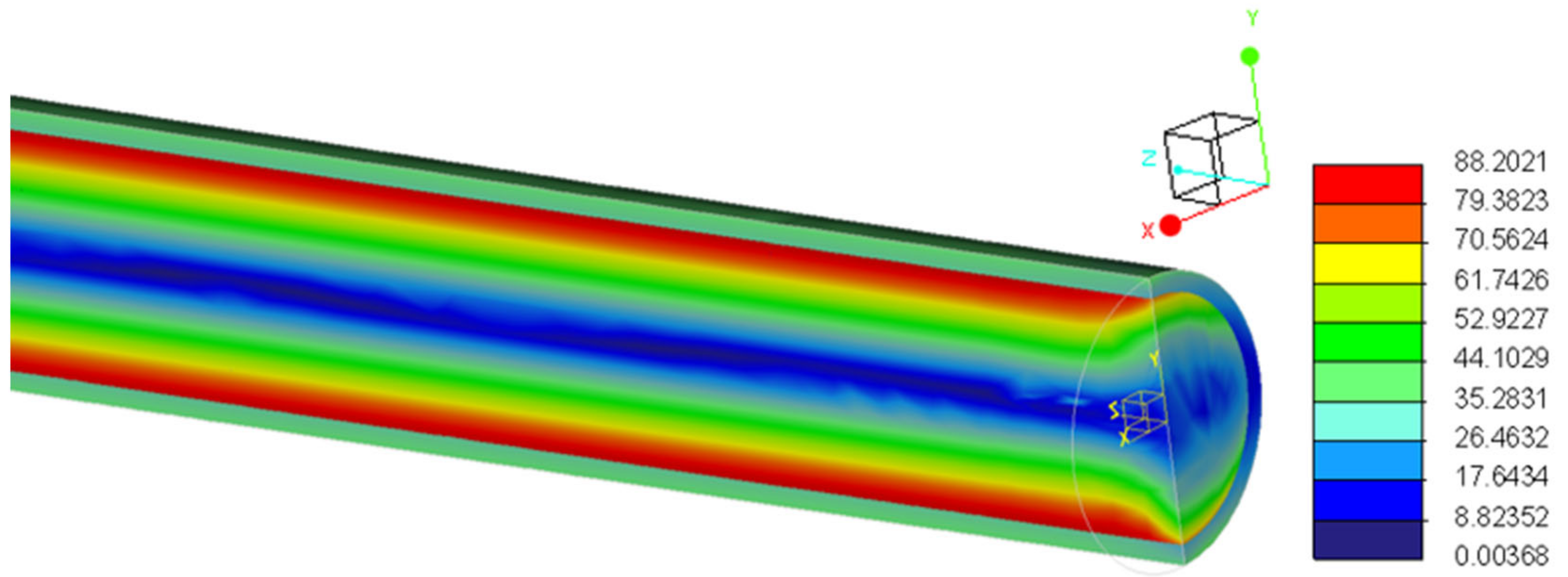
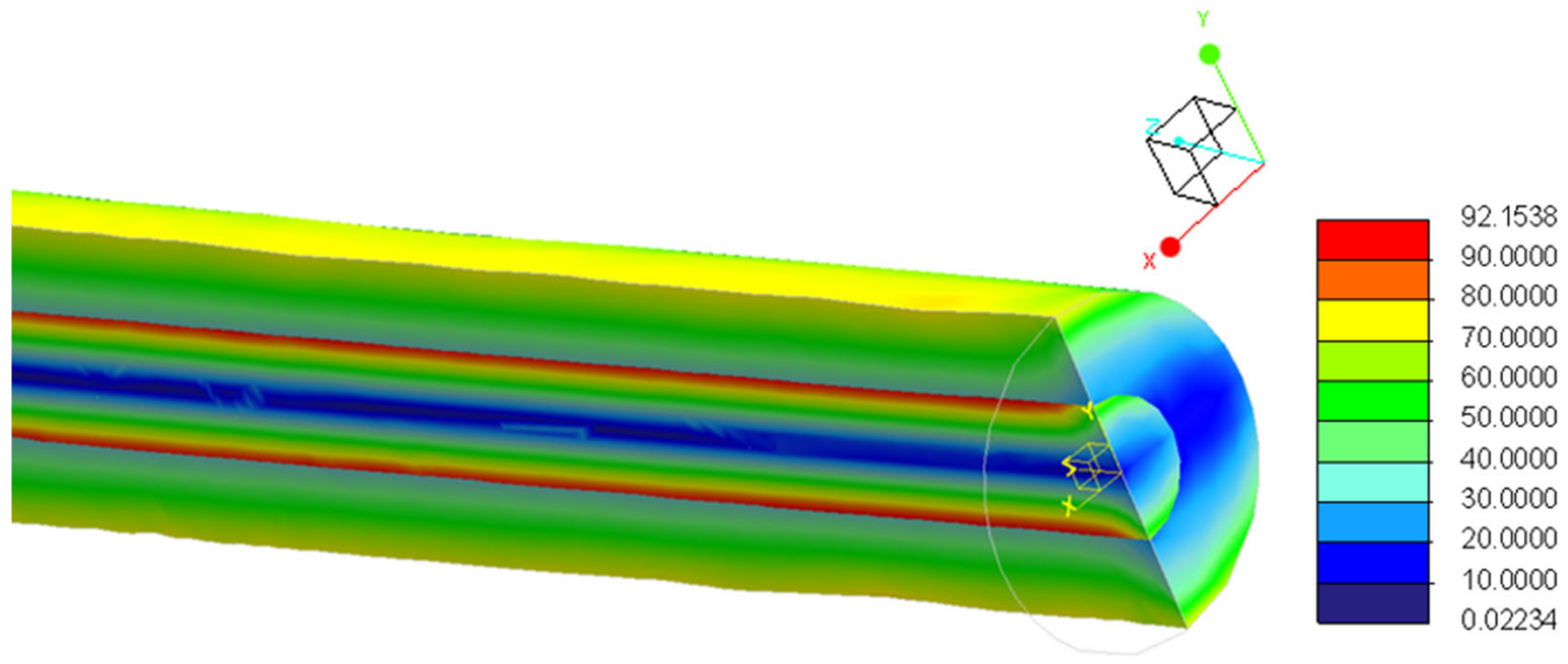
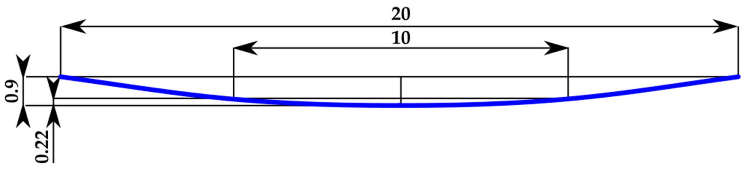
2.3. FEM (Finite Element Method) Analysis of the Magnetic Microwire
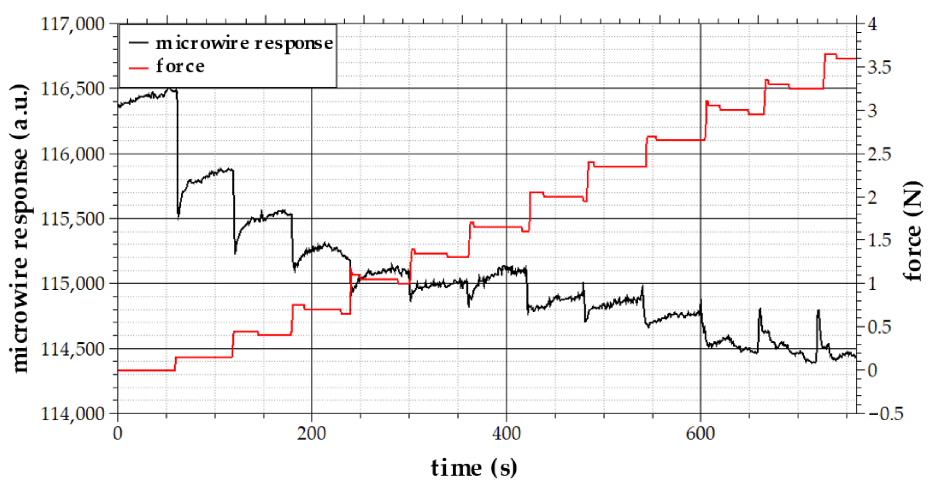
The aim of this study was to confirm if the magnetic microwire can be used as a sensing element for the tensile stress sensor even in conditions when cyclic mechanical loading is applied. Due to their dimensions, the magnetic microwires can be easily integrated into the belt during the manufacturing process without the structural violations of the hyper elastic material. Therefore, the precise finite element method (FEM) model of the microwire was created involving the contact areas between the core and glass-coating of the microwire based on the microscope pictures. The more detail description dealing with the FEM model of the microwire was a part of our previous research and can be found in [55]. The goal of this paper is to present the methodology for the further application and development of the FEM model of the microwire. Therefore, the FEM model of the amorphous glass-coated magnetic microwire was used for the simulations and visualization of the mechanical stresses of the magnetic microwire during the conveyor belt operation which predicts the lifetime of the sensing part of the sensors based on the magnetic microwires.
During the pipe conveyor belt operation, the belt is enclosed, whereas considering the studied experimental belt conveyor and the belt width of 400 mm, the outer diameter of the enclosed belt was in our case 127 mm. During the enclosing of the belt, the microwire integrated in the belt is bent and therefore cyclically mechanically loaded during the operation. Considering the microwire with the length of 20 mm and the experimental conveyor belt characteristics, this deformation caused by the bending is up to 0.9 mm. For the simulation of the mechanical loading of the microwire, the CAD/CAE model created in the Creo simulation software from the PTC company was used.
At first, the deformation of the microwire caused by the bending during the enclosing of the belt was simulated. In these simulations, the mechanical properties of the microwire during the cyclical mechanical loading of the microwire embedded in the hyper elastic material of the conveyor belt were analyzed. Material properties were defined according to the chosen microwire type consisting of the Fe-based metallic core with the glass coating. Due to the simulation results, it was possible to determine mechanical stresses of the microwire core and its glass coating and consequently to estimate the fatigue life of the microwire during the operation, which is crucial if we consider the cyclic mechanical loading of the microwire during the operation of the pipe belt conveyor.
The first performed analysis was the static analysis of the mechanical loading corresponding to the maximal deviation from the initial state achieving the bending up to the 0.9 mm calculated from the geometrical dimensions of the pipe belt conveyor. Consequently, for the state corresponding to the enclosed pipe conveyor belt, the force acting on the end of the microwire was calculated and applied as the input of the verifying simulations. Considering the symmetrical FEM microwire model, its value was 1.5 × 10⁻⁵ N. The knowledge of this force was necessary for the determination of the input parameters of the fatigue life analysis.
Subsequently, the PTC Creo Fatigue Advisor Extension module for the prediction of the lifetime of the microwire integrated into the technical rubber belt was applied. The PTC Creo Fatigue Advisor Extension expands the capabilities of the PTC Creo Simulate and allows the evaluation of the product design for durability. Using the PTC Creo Fatigue Advisor Extension, we can predict the life of structures that are prone to fatigue failure under the cyclic loading and to investigate the impact that the design changes have on their endurance. For the simulation, the previously performed static analysis results, together with the load history, were used. In the load history, the cyclic loading with the constant amplitude from the initial zero state to the calculated peak value defined by the calculated acting force were applied.
The results of the static analyses are presented in the form of the displacement magnitude and stress von Mises of the glass-coated magnetic microwires. From the simulation results, the fatigue log life, representing the estimated number of cycles until the model breaks expressing the life as a logarithm due to the exponential nature of the fatigue, and the fatigue factor of safety, representing the permissible factor of safety on the input load for the magnetic microwires, were estimated.
For a comparison, the simulations were performed also for the microwires with different core diameters and glass coating thicknesses and also for various microwire lengths. The knowledge of the mechanical characteristics of the microwires with various geometrical dimensions that can be integrated in the pipe conveyor belt is necessary for the further development of the microwire-based sensors used for the pipe conveyor belt non-destructive testing, monitoring, and diagnostics.

3. Results

The initial measurement results performed with the testing sample prepared from the technical rubber with the embedded glass-coated microwire with the chemical composition Fe77.5Si7.5B15 and length of 20 mm can be seen in Figure 2. From the proof-of concept measurement results it can be seen that the step change of the applied mechanical loading (force) lead to the step change of the microwire response. The performed measurements were very important, as they served as the confirmation of the utilization possibility of the microwire-based sensor with the microwire integrated directly into the hyper elastic material. Presently, only measurements of solid composite materials have been performed.
Due to the singularity of the pipe conveyor belt and the cyclical periodical mechanical loading of the microwire, focus was directed to the analysis of the lifetime of the microwire as the sensitive part of the microwire-based sensor affected by the cyclical mechanical loading.
The simulation results can be seen in Figure 3, where the bend deformation of the glass-coated magnetic microwire in mm during the operation can be seen. In this case, the same microwire as in the proof-of-concept measurements was analyzed.
During the simulations, due to the symmetrical characteristics of the microwire and also due to the fact that from the calculation demands it is more convenient to define boundary conditions for the symmetrical models, in the simulation results, only one half of the microwire can be seen.
Consequently, in Figure 4, the mechanical stresses of the same microwire model in MPa are presented.
With the PTC Creo Fatigue Advisor Extension, it is possible to estimate the number of the load cycles that our model can sustain before a failure occurs. From the results shown in Figure 4 with the visualization of the static stress and in Figure 5 showing the log life plots, it can be seen where the fatigue cracks are likely to form.
The minimum log life obtained from the simulation results is 7.27646 which means 107.27646 or 18,899,921 cycles at points where the stress von Mises reaches the maximum values. It can be seen that the minimum values of the fatigue log life are on the surface of the microwire, although the maximum values of the stress von Mises can be expected on the surface of the metallic core. This is caused by the different material properties of the core and coating of the microwire, thus for the fatigue log life analyses, the glass coating is a determining factor because the glass is fragile and has lower strength in comparison to the metallic core. The minimum fatigue factor of safety shown in Figure 6 suggests a permissible overload before the fatigue life is jeopardized.
Because the microwire consists of the metallic core and the glass coating with the different material characteristics, it is necessary to consider the microwire as a complex material structure. For the further development and optimization of the microwire-based sensor, the mechanical properties of the microwires with the different metallic core diameters and with the various glass coating thicknesses were compared. During these simulations, we considered the unchanged microwire length of 20 mm and the same chemical composition of the microwires as in the previous simulations. In the simulations, the mechanical loading during the bending of the pipe conveyor belt caused by the enclosing of the belt was evaluated. By the enclosing of the conveyor belt, we considered the same deformation of 0.9 mm.
For all of the performed simulations, the acting force causing the deformation during the bending needed to be calculated and their values for the chosen microwire types were compared and are summarized in Table 1.
The simulation results showing the stress von Mises of the magnetic microwires for the different microwire and for the microwire core diameters can be seen in Figure 7, Figure 8 and Figure 9.
From the simulation results, we can again obtain information about the mechanical stress distribution in the microwire core and its coating (see Figure 7, Figure 8 and Figure 9) and to determine the values of the stresses von Mises. We can also calculate the predicted lifetime of the microwires represented by the microwire fatigue log life values and the corresponding number of the zero-peak cycles, which are a determining factor from an operational point of view because from to this value we can predict the lifetime of the microwire for the specific type of the pipe conveyor belt. The simulation results summarized in Table 1 also include the calculated values of the fatigue factor of safety, estimating the factor based upon the predicted failure of the microwire.
The following research was focused on the study and on the analysis of the influence of the microwire length on the mechanical characteristics of the bended microwire. During these simulations, we considered the microwire core diameter of 15 μm and the overall microwire diameter of 35 μm corresponding to the first analyzed microwire. Furthermore, the chemical composition of the microwire remains the same. For the different microwire lengths we must consider that the diameter of the bending remains the same; however, if we consider the microwire length of 10 mm for example, it means half of the length in comparison to the previously analyzed microwires, the bending of the microwire end will achieve the value of 0.22 mm, as it can be seen in Figure 10.
The acting force causing the deformation during the bending is of course dependent on the microwire length. In our case, it means for the half microwire length, the acting force was two times higher and achieved the value of 3 × 10⁻⁵ N because the dependence is inversely proportional, as the same bending moment must be applied. The mechanical stress distribution in the microwire core and its coating corresponds to Figure 4. From the simulation results it can be seen that in the stress von Mises value, only a small deviation with the value of 1 MPa was calculated, and very similar values of the fatigue log life together with the corresponding number of the cycles that it is expected that the microwires will withstand during the pipe conveyor belt operation and the fatigue factor of safety were obtained. From the analyses results summarized in Table 2, it can be seen that the estimated values varied only in a range up to 4%. Therefore, from the performed analyses it can be concluded that the microwire length will not have an influence on the overall lifetime of the microwire because the obtained deviation was only a result of the rounding applied during the numerical analysis, as considering the ratio of the microwire length and diameter, during the FEM analysis of the microwire, there are high calculation demands.

4. Discussion

The initial measurement results performed with the microwire-based sensor with the sensitive part of the sensor represented by the glass-coated magnetic microwire proved the utilization possibility of this type of sensor and for the hyper elastic materials, more specifically in our case, the tested microwire was embedded directly into technical rubber. From the measurement results, it can be seen that the mean value of the response of the microwire with the increasing applied force decreases. This behavior is caused by the releasing of the stresses induced in the microwire as a result of different material (involving also thermal) characteristics of the microwire and technical rubber, as the vulcanization process requires temperatures up to the 160 °C and the consequent cooling causes the additional force acting on the embedded microwire.
Other observed phenomena are the peaks observed in the presented raw unprocessed data. In this case, the reason is the adhesion between the glass-coating of the microwire and the technical rubber.
As these phenomena are deterministic, it can be concluded that the microwire-based sensor can be applied also for the measurement of the tensile stress of the hyper elastic materials. However, for the more precise measurements, the knowledge of the material characteristics of the hyper elastic materials are necessary. Additionally, further research will require modification and following optimization of the sensor design and construction so that it can be used not only on the materials samples in the laboratory conditions, but also in the real practice.
As our research is focused on the intelligent monitoring and diagnostics of the pipe belt conveyors, the focus was on the analyses related to the singularities of this type of conveyor belts.
The results of the FEM analyses shows that the application of the microwire with the overall microwire diameter of 35 μm and with the core diameter of 15 μm in the role of the sensing element of the microwire-based sensor is the most convenient. In this case, the lowest mechanical stresses with the value up to 44 MPa in the microwire core can be seen (Figure 4), and the estimated number of the cycles until the time when the fatigue cracks occur on the surface of the glass coating is 18,899,921 which implies that this value is high enough for the application of the microwire in the role of the sensing element embedded directly into the conveyor belt for the estimated belt conveyor operation during its whole life cycle. In this case, the fatigue factor of safety was the highest with the value of 1.08.
The microwire with the same diameter of 35 μm as in the first case, but with the higher metallic core diameter of 30 μm and with the thickness of the glass coating of only 2.5 μm would be also convenient for the application from the mechanical loading point of view. Due to the higher core stiffness, the maximal mechanical stress can be up to the 88 MPa and the estimated number of cycles until the formation of the fatigue cracks is 13,310,059, which is still a satisfactory value. The fatigue factor of safety was in this case similar to the previous one and achieved the value of 1.04.
Completely different simulation results were obtained in another two cases with the core diameters of 15 μm and 30 μm as in the previous cases, but the overall diameter of the microwire was higher, in both cases it was 70 μm. It caused in both cases a significant decrease in the estimated number of the cycles until the fatigue cracks occurred. The calculated values of the zero-peak cycles were only 199,700 and 157,601, respectively. The fatigue factor safety was lowered significantly to the value of 0.5, and as it can be seen from Figure 7, the maximal mechanical stresses were not observed in the metallic core but in the glass coating of the microwire. In this case, the thickness of the microwire glass-coating is significantly larger in comparison to other cases, as the microwire metallic core has a negligible diameter. The dominant glass coating together with the different mechanical properties of the glass and microwire core cause that the maximum stresses resulting from the different core, and metallic stiffness was shifted from the metallic core to the microwire glass coating. In other cases, the metallic core diameter was dominant, and therefore the transfer of the maximal mechanical stresses during the bending can be observed in the microwire core. Considering the fatigue cracks, they always have a tendency to be created on the microwire glass coating, as the glass is fragile in comparison to the metallic core, and during the bending of the microwire, it is susceptible to cracking on the surface. Therefore, the microwires with the above-mentioned dimensions are not convenient for the application as a sensing element for the microwire-based sensors which will be periodically loaded. From the simulation results, it can be seen that as the microwire with the same ratio of the metallic core and of the glass coating as in the first case can be also considered inconvenient. It can be concluded that the limiting factor of the microwire is the thickness of the glass coating. It is caused by the fact that glass is a fragile material that can be crushed, broken, or otherwise damaged easily due to the cyclic periodical mechanical loading caused by the bending of the pipe conveyor belt during its closing. With the increasing glass thickness of the microwire, the predicted lifetime of the microwire will decrease regardless of the metal core diameter.
Another important factor is that the microwire length will not influence the overall lifetime of the microwire, which is cyclically periodically mechanically loaded. This fact is an important finding mainly from a practical point of view, as during the cutting of the microwire to the desired length, deviations can occur.
During the ongoing long-term research of the magnetic sensors and their applications performed at our faculty, we also proved that microwire-based sensors can be used for the magnetic field and also indirectly for the tensile stress measurement. Due to the improved induction measurement methodology, the formation of the excitation, and measuring coils being placed outside of the microwire, the measurement can be completely contactless. Due to their dimensions, microwire can be embedded into many types of materials without the structural violations of these materials. After the successful measurement of the tensile stresses in the composite material [52], the current research is focused on the application of microwire-based sensors for the diagnostics of pipe belt conveyors. However, the hyper elasticity of the belt, into which the microwire is embedded, led to several problems dealing with the sensor design, construction, and signal processing. Therefore, the modification and optimization of the sensor design will be a part of the further research and development activities. Regarding the utilization of the microwire-based sensors in the diagnostics of the conveyor belt, they can be used for the structural health monitoring of the conveyor belt material and due to the diagnostic results, it will be possible to monitor wear, damage, and ageing of the conveyor belt material, which will help to plan the maintenance or repair procedures more effectively.
Furthermore, microwires can be used in the role of magnetic markers, therefore it will be possible to monitor the velocity of the conveyor belt to measure distance between the magnetic markers and consequently to use the obtained information for the evaluation of the degradation of the material structure, for the more effective tensioning of the conveyor belt, or for stopping of the required part of the conveyor belt in the maintenance area. In this way, it will be possible to shorten the maintenance and repair time intervals and to contribute to the effective predictive planning of the maintenance. Additionally, due to the performed FEM analyses, we can extend the application possibilities of the microwire-based sensors also for the pipe belt conveyors, the utilization of which is very perspective from an environmental point of view, mainly considering the transportation of dusty and fine materials.

5. Conclusions

Pipe belt conveyors are a specific type of belt conveyors, the utilization of which is very advantageous especially considering the transportation of fine or dusty materials in the proximity of towns or cities. Due to the enclosing of the conveyor belt, the air pollution is eliminated significantly and therefore, they contribute to the development of sustainable transportation.
Research in the area of belt conveyors has been extensive; however, there are few studies dealing with the singularities of the pipe belt conveyors. The goal of our research was to prove that the microwire-based sensors with the sensing element consisting of amorphous glass-coated microwires embedded directly into the conveyor belt can be used even for non-destructive testing, monitoring, and diagnostics of pipe conveyor belts. The laboratory measurement results with the microwire-based tensile stress sensors proved that it is possible to measure the tensile stress with the glass-coated magnetic microwire embedded into technical rubber. However, considering the singularities of the pipe belt conveyors and the related cyclic mechanical loading of the microwire causing its periodical bending and unbending during the enclosing of the pipe conveyor belt, further research was focused on the mechanical analyses of the microwire under the periodical loading.
As a result of the performed FEM analyses, it can be concluded that during the selection process of the microwire, emphasis should directed toward the thickness of the glass coating, which can affect the lifetime of the microwire significantly. An important and interesting conclusion is that microwires with the same ratio of the microwire core diameter to the overall diameter can have significantly different values of fatigue factor of safety. Another notable factor is the conclusion that the lifetime of the microwire is not dependent on the length of the microwire, which is important mainly from a practical point of view, because during the manufacturing process and cutting of the microwire, inaccuracies can occur. Additionally, an important factor for our further research, which will be devoted to the modification and optimization of the microwire-based sensor embedded directly into hyper elastic material of the conveyor belt, is that from the performed set of analyses, it is clear that the currently used and tested microwire type has convenient geometrical dimensions and can be used in the pipe conveyor belt operations, as its estimated fatigue log life and therefore the corresponding number of bending cycles until the damage or crack occurs is satisfactory.
The created FEM model and performed analysis will also serve as the basis for the future optimization of the microwire-based sensor. Due to the created methodology, it will be possible to determine lifetime not only of the different types of microwires with various geometrical dimensions, but also with various chemical compositions of the metallic microwire core. Furthermore, thanks to the prepared methodology it will be possible to perform analyses also for the modified dimensions of the belt conveyors or for the different materials of pipe conveyor belts.

Author Contributions

Conceptualization, K.S. and K.D.; methodology, K.S. and K.D.; validation, K.S. and K.D.; formal analysis, K.D.; writing—original draft preparation, K.D.; writing—review and editing, K.D.; visualization, K.S.; project administration, K.S.; funding acquisition, K.S. All authors have read and agreed to the published version of the manuscript.

Funding

This research was funded by the Slovak Research and Development Agency, grant number APVV-18-0248 and grant number APVV-17-0184, Scientific grant agency of the Ministry of Education of the Slovak Republic and of Slovak Academy of Sciences, grant number VEGA 1/0101/22 and the Research Agency, ITMS code number 313011T557.

Institutional Review Board Statement

Not applicable.

Informed Consent Statement

Not applicable.

Data Availability Statement

Not applicable.

Acknowledgments

We would like to acknowledge the EDIS vvd. company for the co-operation on the magnetic measurements and for the support by the technology transfer into practice.

Conflicts of Interest

The authors declare no conflict of interest.

References

  1. Bhattacharya, J.; Gavel, S.; Kumar, S.; Choudhary, A.S. Pipe belt conveyor: Cost estimation under various design constraints. J. Mines Met. Fuels 2019, 67, 345–359. [Google Scholar]
  2. Zareiforoush, H.; Bakhshipour, A.; Bagheri, I. Performance Evaluation and Optimization of a Solar-Assisted Multi-Belt Conveyor Dryer Based on Response Surface Methodology. J. Renew. Energy Environ. 2022, 9, 78–92. [Google Scholar] [CrossRef]
  3. Dos Santos, J.A. Sandwich belt high angle conveyors: In harmony with the environment 2020. In Proceedings of the PEERS/IBBC, Virtual Conference, online, 2–4 November 2020; pp. 39–63. [Google Scholar]
  4. Bortnowski, P.; Król, R.; Nowak-Szpak, A.; Ozdoba, M.A. Preliminary Studies of the Impact of a Conveyor Belt on the Noise Emission. Sustainability 2022, 14, 2785. [Google Scholar] [CrossRef]
  5. Vaka, G.A.; Robins, K. Development and Advantages. Available online: http://www.pipeconveyor.com/Case%20Studies/Advantages/Advantages.htm (accessed on 5 May 2022).
  6. Galkin, V.I. Expanding range of application of pipe conveyor belts through innovative design concepts. Gorn. Zhurnal 2020, 2020, 52–56. [Google Scholar] [CrossRef]
  7. Guo, Y.-C.; Wang, S.; Hu, K.; Li, D.-Y. Optimizing the Pipe Diameter of the Pipe Belt Conveyor Based on Discrete Element Method. 3D Res. 2016, 7, 5. [Google Scholar] [CrossRef]
  8. Zamiralova, M.E.; Lodewijks, G. Shape stability of pipe belt conveyors: From throughability to pipe-ability. FME Trans. 2016, 44, 263–271. [Google Scholar] [CrossRef]
  9. Xiao, D.; Li, X.; He, K. Power Balance of Starting Process for Pipe Belt Conveyor Based on Master-Slave Control. IEEE Access 2018, 6, 16924–16931. [Google Scholar] [CrossRef]
  10. He, D.; Liu, X.; Zhong, B. Sustainable belt conveyor operation by active speed control. Measurement 2020, 154, 107458. [Google Scholar] [CrossRef]
  11. dos Santos e Santos, L.; Ribeiro Filho, P.R.C.F.; Macêdo, E.N. Indentation rolling resistance in pipe conveyor belts: A review. J. Braz. Soc. Mech. Sci. 2021, 43, 230. [Google Scholar] [CrossRef]
  12. Zamiralova, M.E.; Lodewijks, G. Energy consumption of pipe belt conveyors: Indentation rolling resistance. FME Trans. 2012, 40, 171–176. [Google Scholar]
  13. dos Santos e Santos, L.; Ribeiro Filho, P.R.C.F.; Macêdo, E.N. Development of idler for measuring indentation rolling resistance in pipe conveyor belts. Measurement 2020, 153, 107413. [Google Scholar] [CrossRef]
  14. Wang, S.; Li, D.-Y.; Guo, Y.-C. Research on Magnetic Model of Low Resistance Permanent Magnet Pipe Belt Conveyor. 3D Res. 2016, 7, 23. [Google Scholar] [CrossRef]
  15. Molnár, V.; Sabovčík, M. Static testing evaluation of pipe conveyor belt for different tensioning forces. Open Eng. 2019, 9, 580–585. [Google Scholar] [CrossRef]
  16. Stehlikova, B.; Molnar, V.; Fedorko, G.; Michalik, P.; Paulikova, A. Research about influence of the tension forces, asymmetrical tensioning and filling rate of pipe conveyor belt filled with the material on the contact forces of idler rolls in hexagonal idler housing. Measurement 2020, 156, 107598. [Google Scholar] [CrossRef]
  17. Zheng, Q.J.; Xu, M.H.; Chu, K.W.; Pan, R.H.; Yu, A.B. A coupled FEM/DEM model for pipe conveyor systems: Analysis of the contact forces on belt. Powder Technol. 2017, 314, 480–489. [Google Scholar] [CrossRef]
  18. Zamiralova, M.E.; Lodewijks, G. Measurement of a pipe belt conveyor contact forces and cross section deformation by means of the six-point pipe belt stiffness testing device. Measurement 2015, 70, 232–246. [Google Scholar] [CrossRef]
  19. Wang, S.; Guo, Y.-C.; Li, D.-Y.; Hu, K. Research of lateral force of pipe conveyor belt’s vertical transport section. Arch. Transp. 2016, 37, 67–75. [Google Scholar] [CrossRef] [Green Version]
  20. Guo, Y.-C.; Wang, S.; Hu, K.; Li, D.-Y. Optimization and experimental study of transport section lateral pressure of pipe belt conveyor. Adv. Powder Technol. 2016, 27, 1318–1324. [Google Scholar] [CrossRef]
  21. Wang, S.; Li, D.; Hu, K. Analysis and Experimental Study on Pressure Characteristics of Supporting Roller Group of Pipe Belt Conveyor. Shock. Vib. 2019, 2019, 7061847. [Google Scholar] [CrossRef] [Green Version]
  22. Bin, G.; Zhang, W.; Li, X.; Ye, G. Dynamic contact force analysis considering pipe conveyor belt elasticity. Meitan Xuebao/J. China Coal Soc. 2017, 42, 2483–2490. [Google Scholar] [CrossRef]
  23. Xiaoxia, S.; Wenjun, M.; Hui, Z.; Yuan, Y.; Zhengmao, Y. Analysis on the bending stiffness and the form force of the pipe conveyor belt. Sens. Transducers 2013, 161, 655–660. [Google Scholar]
  24. Minkin, A.; Jungk, A.; Hontscha, T. Belt replacement at a long distance pipe conveyor: Belt design, installation and power measurements. Bulk Solids Handl. 2012, 32, 16–21. [Google Scholar]
  25. Yasutomi, A.Y.; Enoki, H. Localization of Inspection Device Along Belt Conveyors With Multiple Branches Using Deep Neural Networks. IEEE Robot. Autom. Lett. 2020, 5, 2921–2928. [Google Scholar] [CrossRef]
  26. Yasutomi, A.Y.; Enoki, H.; Yamaguchi, S.; Tamura, K. Inspection System for Automatic Measurement of Level Differences in Belt Conveyors Using Inertial Measurement Unit. In Proceedings of the IEEE/RSJ International Conference on Intelligent Robots and Systems, Madrid, Spain, 1–5 October 2018; pp. 6155–6161. [Google Scholar]
  27. Szrek, J.; Jakubiak, J.; Zimroz, R.A. Mobile Robot-Based System for Automatic Inspection of Belt Conveyors in Mining Industry. Energies 2022, 15, 327. [Google Scholar] [CrossRef]
  28. Rocha, F.; Garcia, G.; Pereira, R.F.S.; Henrique, D.F.; Thales, H.S.; Ricardo, H.R.A.; Evelyn, S.B.; André, A.; Emanuel, C.; Wagner, A.; et al. ROSI: A Robotic System for Harsh Outdoor Industrial Inspection—System Design and Applications. J. Intell. Robot. Syst. Theory Appl. 2021, 103, 30. [Google Scholar] [CrossRef]
  29. Chamorro, J.; Vallejo, L.; Maynard, C.; Guevara, S.; Solorio, J.A.; Soto, N.; Singh, K.V.; Bhate, U.; Ravi, K.G.V.V.; Garcia, J.; et al. Health monitoring of a conveyor belt system using machine vision and real-time sensor data. CIRP J. Manuf. Sci. Technol. 2022, 38, 38–50. [Google Scholar] [CrossRef]
  30. Liu, Y.; Miao, C.; Li, X.; Ji, J.; Meng, D. Research on the fault analysis method of belt conveyor idlers based on sound and thermal infrared image features. Measurement 2021, 186, 110177. [Google Scholar] [CrossRef]
  31. Zeng, F.; Zhang, S.; Wang, T.; Wu, Q. Mini-crack detection of conveyor belt based on laser excited thermography. Appl. Sci. 2021, 11, 10766. [Google Scholar] [CrossRef]
  32. Dabek, P.; Szrek, J.; Zimroz, R.; Wodecki, J. An Automatic Procedure for Overheated Idler Detection in Belt Conveyors Using Fusion of Infrared and RGB Images Acquired during UGV Robot Inspection. Energies 2022, 15, 601. [Google Scholar] [CrossRef]
  33. Wang, Y.; Li, S.; Meng, W. Thermo-mechanical strong coupling analysis on braking device of pipe belt conveyor. J. Mech. Sci. Technol. 2018, 32, 1277–1285. [Google Scholar] [CrossRef]
  34. Yang, Y.; Hou, C.C.; Qiao, T.Z.; Zhang, H.T.; Ma, L. Longitudinal tear early-warning method for conveyor belt based on infrared vision. Measurement 2019, 147, 106817. [Google Scholar] [CrossRef]
  35. Shiri, H.; Wodecki, J.; Ziętek, B.; Zimroz, R. Inspection robotic UGV platform and the procedure for an acoustic signal-based fault detection in belt conveyor idler. Energies 2021, 14, 7646. [Google Scholar] [CrossRef]
  36. Popescu, F.D. Ways of controlling transport capacity variation of belt conveyors. In Proceedings of the 9th WSEAS International Conference Automation and Information (ICAI’08), Bucharest, Romania, 24–26 June 2008; pp. 120–123. [Google Scholar]
  37. Wang, Y.; Miao, C.; Liu, Y.; Meng, D. Research on a sound-based method for belt conveyor longitudinal tear detection. Measurement 2022, 190, 110787. [Google Scholar] [CrossRef]
  38. Yang, M.; Peng, C.; Li, Z. An Audio-based Intelligent Fault Classification System for Belt Conveyor Rollers. In Proceedings of the Chinese Control Conference, CCC, Shanghai, China, 26–28 July 2021; pp. 4647–4652. [Google Scholar] [CrossRef]
  39. Martínez Quintero, J.C.; Estupiñán Cuesta, E.P.; García Ramírez, J.S. Reconfigurable software-defined radar testbed with built-in validation. Bull. Electr. Eng. Inform. 2022, 11, 825–837. [Google Scholar] [CrossRef]
  40. Ma, G.; Lu, J.; Gao, M. Design of metal detecting system based on HMC1001 magnetic sensor. In Proceedings of the 13th IEEE Conference on Industrial Electronics and Applications, ICIEA 2018, Wuhan, China, 31 May–2 June 2018; pp. 1703–1708. [Google Scholar] [CrossRef]
  41. Błażej, R.; Jurdziak, L.; Kozłowski, T.; Kirjanów, A. The use of magnetic sensors in monitoring the condition of the core in steel cord conveyor belts —Tests of the measuring probe and the design of the DiagBelt system. Measurement 2018, 123, 48–53. [Google Scholar] [CrossRef]
  42. Dey, S.; Salim, O.; Masoumi, H.; Karmakar, N.C. A Novel UHF RFID Sensor Based Crack Detection Technique for Coal Mining Conveyor Belt. IEEE J. Radio Freq. Identif. 2022, 6, 19–30. [Google Scholar] [CrossRef]
  43. Buffi, A.; Nepa, P.; Lombardini, F. A phase-based technique for localization of uhf-rfid tags moving on a conveyor belt: Performance analysis and test-case measurements. IEEE Sens. J. 2015, 15, 387–396. [Google Scholar] [CrossRef]
  44. Megalou, S.; Chatzistefanou, A.R.; Tzitzis, A.; Yioultsis, T.V.; Dimitriou, A.G. Passive UHF-RFID Hyperbolic Positioning of Moving Tags by Exploiting Neural Networks. IEEE J. Radio Freq. Identif. 2022, in press. [Google Scholar] [CrossRef]
  45. Guo, X.; Liu, X.; Zhou, H.; Stanislawski, R.; Królczyk, G.; Li, Z. Belt Tear Detection for Coal Mining Conveyors. Micromachines 2022, 13, 449. [Google Scholar] [CrossRef]
  46. Andrejiova, M.; Grincova, A.; Marasova, D. Monitoring dynamic loading of conveyer belts by measuring local peak impact forces. Measurement 2020, 158, 107690. [Google Scholar] [CrossRef]
  47. Ravikumar, S.; Kanagasabapathy, H.; Muralidharan, V. Multi-component fault diagnosis of self aligning troughing roller (SATR) in belt conveyor system using decision tree-A statistical approach. FME Trans. 2020, 48, 364–371. [Google Scholar] [CrossRef]
  48. Zhang, M.; Zhang, Y.; Zhou, M.; Jiang, K.; Shi, H.; Yu, Y.; Hao, N. Application of lightweight convolutional neural network for damage detection of conveyor belt. Appl. Sci. 2021, 11, 7282. [Google Scholar] [CrossRef]
  49. Kozłowski, E.; Borucka, A.; Liu, Y.; Mazurkiewicz, D. Conveyor Belts Joints Remaining Life Time Forecasting with the Use of Monitoring Data and Mathematical Modelling. In Proceedings of the 1st International Conference on Innovation in Engineering, ICIE 2021, Guimarães, Portugese, 28–30 June 2022; pp. 44–54. [Google Scholar] [CrossRef]
  50. Selvam, S.T.; Mukhopadhyay, A.K. Numerical Analysis of Belt Conveyors for Maintenance Decision Support System. Int. J. Eng. Trends Technol. 2022, 70, 151–161. [Google Scholar] [CrossRef]
  51. Liu, X.; He, D.; Lodewijks, G.; Pang, Y.; Mei, J. Integrated decision making for predictive maintenance of belt conveyor systems. Reliab. Eng. Syst. Saf. 2019, 188, 347–351. [Google Scholar] [CrossRef]
  52. Šmelko, M.; Draganová, K.; Lipovský, P.; Semrád, K.; Blišt’anová, M.; Kašper, P. Non-destructive testing of aircraft structures using microwire-based tensile stress sensor. Appl. Sci. 2020, 10, 8218. [Google Scholar] [CrossRef]
  53. Hudák, J.; Lipovský, P.; Bajús, J.; Čverha, A.; Klein, P.; Varga, R.; Onufer, Z.; Ziman, J. Fluxgate Sensors Based on Magnetic Microwires for Weak Magnetic Fields Measurement. J. Electr. Eng. 2015, 66, 153–156. [Google Scholar]
  54. Šmelko, M.; Kravčák, J.; Praslička, D.; Blažek, J.; Draganová, K. Impact of Modified Endings on Noise Characteristics of Fe-Based Glass-Coated Microwires. J. Electr. Eng. 2015, 66, 30–32. [Google Scholar]
  55. Spodniak, M.; Semrád, K.; Šmelko, M.; Fozo, L.; Andoga, R.; Draganová, K.; Szabo, S. Estimation of Magnetic Microwire Mechanical Properties by FEM Modeling. Acta Physica Polonica A 2020, 137, 674–676. [Google Scholar] [CrossRef]
Figure 1. Pipe conveyor belt.
Sustainability 14 08536 g001
Figure 2. Response of the sample prepared from the technical rubber with the embedded glass-coated magnetic microwire on the applied force.
Sustainability 14 08536 g002
Figure 3. Displacement magnitude of the magnetic microwire (mm).
Sustainability 14 08536 g003
Figure 4. Stress von Mises of the magnetic microwire (MPa); microwire diameter: 35 μm, microwire core diameter: 15 μm.
Sustainability 14 08536 g004
Figure 5. Fatigue log life of the magnetic microwire; microwire diameter: 35 μm, microwire core diameter: 15 μm.
Sustainability 14 08536 g005
Figure 6. Fatigue factor of safety of the magnetic microwire; microwire diameter: 35 μm, microwire core diameter: 15 μm.
Sustainability 14 08536 g006
Figure 7. Stress von Mises (MPa) of the magnetic microwire; microwire diameter: 70 μm, microwire core diameter: 15 μm.
Sustainability 14 08536 g007
Figure 8. Stress von Mises (MPa) of the magnetic microwire; microwire diameter: 35 μm, microwire core diameter: 30 μm.
Sustainability 14 08536 g008
Figure 9. Stress von Mises (MPa) of the magnetic microwire; microwire diameter: 70 μm, microwire core diameter: 30 μm.
Sustainability 14 08536 g009
Figure 10. Bending of microwires with different lengths.
Sustainability 14 08536 g010
Table 1. Comparison of the FEM (Finite Element Methods) analysis results of the microwires with the different microwire and microwire core diameters.
Microwire
Diameter (μm)
Microwire Core Diameter (μm)Force (N)Stress von Mises (MPa)Fatigue Log Life (-)Number of Zero-Peak Cycles (-) Fatigue Factor of Safety (-)
35151.5 × 10−5447.2764618,899,9211.08
70152.2 × 10−4675.30038199,7000.5
35303 × 10−5887.1241813,310,0591.04
70302.5 × 10−4925.19756157,6010.5
Table 2. Comparison of FEM (Finite Element Methods) analysis results of microwires with different microwire lengths.
Microwire Length (mm)Microwire
Diameter (μm)
Microwire Core
Diameter (μm)
Force (N)Stress von Mises (MPa)Fatigue Log Life (-)Number of Zero-Peak Cycles (-) Fatigue Factor of Safety (-)
2035151.5 × 10−5447.2764618,899,9211.08
1035153 × 10−5437.2617418,270,0611.083
Publisher’s Note: MDPI stays neutral with regard to jurisdictional claims in published maps and institutional affiliations.

