Article

Fuel Cell Hybrid Locomotive with Modified Fuzzy Logic Based Energy Management System

Department of Energy, Politecnico di Milano, 20156 Milan, Italy
*
Author to whom correspondence should be addressed.
Sustainability 2022, 14(14), 8336; https://doi.org/10.3390/su14148336
Submission received: 11 May 2022 / Revised: 4 July 2022 / Accepted: 4 July 2022 / Published: 7 July 2022

Abstract

:
As one of the most environmentally friendly energy sources today, fuel cells have become the focus of research in countries around the world, especially in the electric transportation field. This paper mainly studies the modeling of fuel cell hybrid locomotives (FCHL) including fuel cells, batteries, motors, and energy management systems. To increase the operating efficiency and improve the performance of FCHL, a modified fuzzy logic-based energy management system (MFL-EMS) is proposed and compared with the traditional power flow energy management system (PF-EMS). Meanwhile, a modified fuel cell hybrid power system model for locomotives is proposed, taking into account the traction motor features that, compared with a simplified controlled source load, can directly reflect the status of the locomotive running speed and the output power of the traction motor load. The proposed system parameters and configurations are determined by combining the characteristics of power and energy density, response characteristics, and charging/discharging characteristics of fuel cells and batteries. The precise simulation results revealed that adopting the proposed MFL-EMS in comparison to the traditional PF-EMS, reduced the hydrogen consumption by 2.943%. Comparing the battery output voltage, it is confirmed that with MFL-EMS it tends to be steeper than the one with PF-EMS, showing the proposed strategy’s robustness. Overall, the obtained results revealed an improved performance in terms of power distribution as well as SOC, which means less hydrogen consumption and therefore a more economical solution.

1. Introduction

For many years, land vehicles such as internal combustion engine vehicles, internal combustion locomotives, etc., that use heat engines as power devices have obtained the necessary power sources by burning hydrocarbon fossil fuels and, at the same time, they have also increased environmental pollution [1,2]. Unlike diesel locomotives, which are limited by the installed power of diesel engines, electric locomotives have higher dynamic performance and have significant advantages when running through long ramps, tunnels, and heavy loads. Based on popular belief, electric vehicles and electric locomotives have the advantage of low emissions and zero pollution. However, it should be noted that although electrical energy is clean with low pollution during use, a large number of pollutant emissions will be generated during the conversion from other forms of energy to electrical energy. In comparison to electric locomotives, hybrid locomotives have outstanding advantages in energy saving and emission reduction. They are also globally recognized as the research and development direction of green and environmentally friendly locomotives. Owing to its advantages, fuel cells can be a viable replacement for the conventional transportation technologies running with diesel [3]. Therefore, the demand for hybrid locomotives is increasing all around the world. However, fuel cells also have several disadvantages, such as high cost, generation of hydrogen, and a shorter lifetime [4]. Accordingly, the combination of fuel cells with some energy storage systems (ESS) is an alternative solution that can help to increase their performance. ESS could reduce the demand for the peak power of the fuel cell system and help realize a ‘flat’ demand for traction power [5,6]. In addition, it can effectively recover braking energy and improve vehicle efficiency [7]. Different ESS systems used for railway systems are discussed in detail in [8]. Meanwhile, fuel cell and battery hybrid power sources can compensate for the slow response time issue. Related research on fuel cell locomotive technology started in the early 1990s [9]. In 2002, the American Vehicle Project LLC and the Fuel Cell Propulsion Association jointly developed the world’s first pure fuel cell traction locomotive with a power of 17 kW [10]. In 2006, JR East Japan Railway Co., Ltd. completed the development of the world’s first fuel cell locomotive. The onboard battery recovered braking energy, which can save 20% of energy compared with ordinary locomotives [11]. Burlington North America the Santa Fe (BNSF) railway company proposed a model of a shunting locomotive in a large mixed yard in 2007 [12]. In January 2008, BNSF officially launched the fuel cell shunting locomotive project, which uses a 250 kW proton exchange membrane fuel cell stack (FCS) and up to 1 MW of instantaneous power. In 2016, French Alstom developed the world’s first fuel cell train to replace non-electric intercity trains powered by diesel engines. In 2021, China’s first self-developed hydrogen-powered hybrid locomotive rolled off the production line at CRRC Datong Co., Ltd. in north China’s Shanxi Province [13]. The hybrid power distribution strategies have been widely utilized in FCHL. Accordingly, designing a suitable energy management strategy (EMS) to make the energy distribution reasonable is the key aspect to ensuring the system operates stably and efficiently. It has attracted the attention of many studies and researchers in this field. For example, Fadel et al. proposed a streamlining approach that could accomplish higher framework effectiveness than regular PI control and fluffy rationale control (FRC) [14]. In [15], a force-the-board technique to limit the hydrogen utilization for the mixture powertrain is presented. Xie et al. planned fluffy coherent energy as the executive’s way to deal with settling the voltage of a direct current bus [16]. Authors in [17] proposed a strong PI control methodology that could diminish the utilization of hydrogen effectively; likewise, the heap pressure of the power device turns out to be less through utilizing the procedure, thus the proposed technique is advantageous to broadening the lifetime of the energy unit. Hong et al. proposed an EMS technique dependent on a dynamic following coefficient (ECMS-DFC), which could keep up with the entire effectiveness of a power module cross-breed framework above 44% while running it into the scaled down, real-drive pattern of the locomotive [18]. Peng et al. proposed a forward dynamic programming-based algorithm and a rule-based online strategy for EMS, which helps facilitate power distribution between the battery and the fuel cell [19]. The optimization-based methodology for using particle swarm optimization for a fuel cell battery hybrid locomotive is proposed in [20]. There are, additionally, numerous different investigations on EMS, evaluating the hybrid framework such as the methodology dependent on Pontryagin’s minimum principle [21,22], Metaheuristic optimization techniques [23], fluffy rationale control [24], speed trajectory optimization by Improved Pathfinder algorithm [25], least identical hydrogen consumption [26], etc. However, the majority of these EMSs are presented for simple and low-power road vehicles and are not specified for large-scale, high-power, and time-varying rail vehicles. Fuzzy logic-based EMSs for FCHL have received limited attention from some experts for the past few years. To get high efficiency, a power-sharing strategy based on a combination of FLC and the Haar wavelet transform is presented for an EMS of the hybrid tramway in [27]. This method is also taking advantage of supercapacitors which in turn leads to increased costs, but it is too complex for real-case implementation. To propose a modest EMS which is appropriate for locomotives, this paper proposes a modified fuzzy logic control energy management strategy (MFL-EMS), considering the power and energy requirements of the fuel cell hybrid locomotive under different traction conditions such as acceleration, cruising, coasting, and braking modes, and compare its performance with the traditional power flow energy management system (PF-EMS). In previous studies, the power demand of a railway system contains many instantaneous variations, and the presented methods are not adequately capable to address it and balance the energy efficiency and dynamic features together with the lifetime of the ESS because of the substantial negative effects of the fluctuations in real driving cycles. The proposed MFL-EMS offers a considerably simple way to get the best performance from ambiguous data in uncertain and time-varying areas such as railway systems, which allows for the modeling of such complex systems. It can provide a totally promising solution compared to conventional control methods, especially for railway systems with nonlinear behaviors where the extraction of the mathematical model is complex to obtain. The structural arrangement of this paper is divided into the following parts: Section 2 describes the methodology, including the modeling of power systems for proposed FCHL including fuel cell, battery, power electronic converters, and traction motors together with the proposed MFL-EMS, which is explained in detail considering the quantization factor and fuzzification rules. Finally, Section 3 and Section 4 are dedicated to simulation demonstrations and the conclusion part, respectively.

2. Methodology

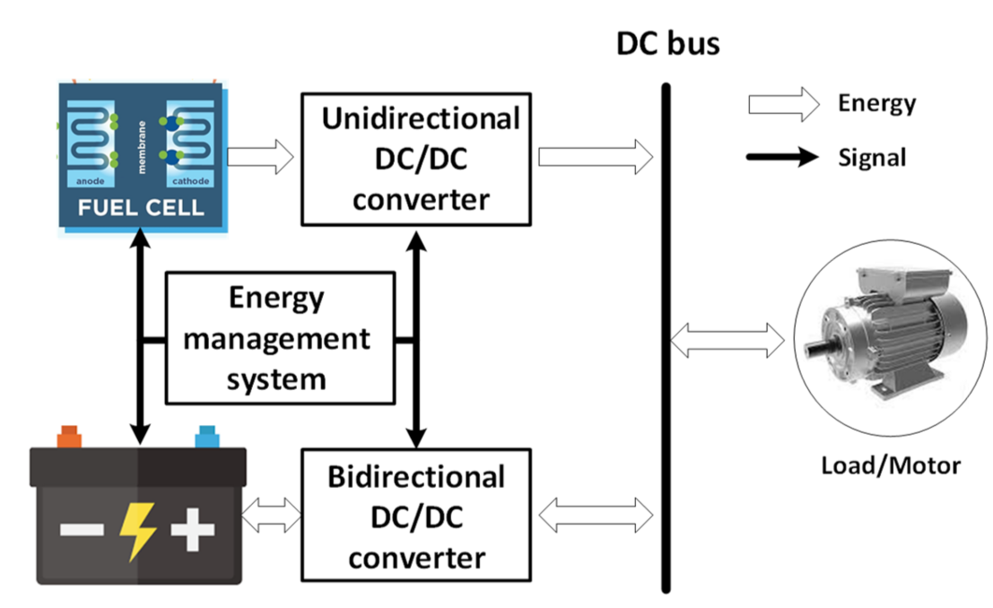
2.1. Modeling of Power System for Fuel Cell Hybrid Locomotive

The topology of the FCHL system commonly includes fuel-cell sets as the power system, a battery as the auxiliary power system and ESS, an electric load as the motor, and an energy management system. However, considering that the fuel cell has no ability for energy storing, and it is also easy to influence by the fact that load changes and fuel cell polarization losses to the output voltage, it will cause the DC bus voltage of the output to be unstable. Thus, it needs to get a steady output voltage with electric and electronic technology. From this point of view, the classification of topologies could be done as direct connections and indirect connections. The structure shown in Figure 1 is adopted by most fuel cell hybrid power systems (FCHPS). In this topology, the fuel cell is used as the main power source to provide power constantly, and the battery as the auxiliary source provides power and recovers regenerative braking energy. Depending on the specific working conditions such as the last mile, the battery can also drive the vehicle in a pure electric mode alone. The specific energy flow is also shown in the mentioned figure.
The FCHPS for locomotives is a large and complex nonlinear system. At present, the FCHPS adopts a method of load modeling based on a current controlled source. By evaluating the speed curve under a certain drive-cycle condition, calculating the actual required power of the system, and using this power to control the current controlled source for simulation, simulation gets easier. For a traction motor, it is assumed that it is equivalent to the power load, thus ignoring the traction characteristics and control issues of the motor. Therefore, in order to analyze the operating characteristics and status of electric locomotives, the establishment of an FCHPS model for locomotives based on traction motors is necessary. Moreover, it also lays the foundation for the study of energy management methods of FCHPSs.

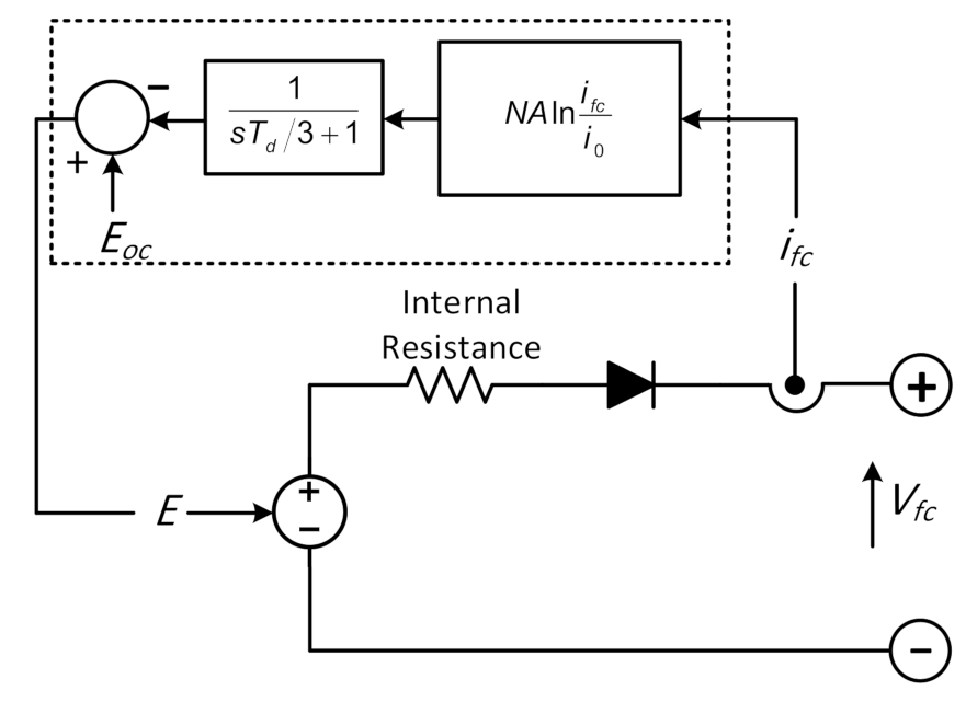
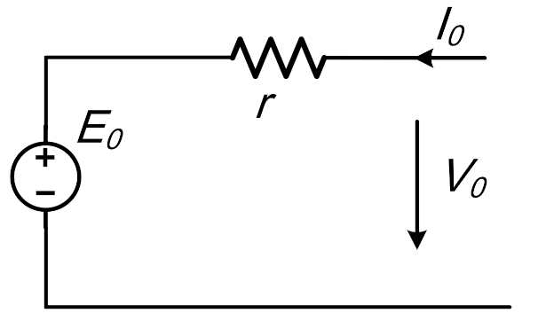
2.1.1. Modeling of Fuel Cell

The fuel of the fuel cell is mainly hydrogen, and hydrocarbons such as methanol, natural gas, and gasoline are also used. Due to the different electrolytes’ applications, significant differences exist in reaction principles, materials, operating conditions, structure, power generation performance, functions, existing problems, and commercialization processes. The development of fuel cells has gone from the first generation through to the fifth generation: the proton exchange membrane fuel cell (PEMFC). Compared with other fuel cells, PEMFC has the advantages of high efficiency, a low working temperature, a fast response speed, and it is the most widely used fuel cell. In recent years, many research results have been made according to the model, control, and characteristic analysis of the PEMFC. In this paper, the PEMFC is used as the main power source of the fuel cell hybrid power system.
The various electrochemical reaction equations of the PEMFC fed with a hydrogen-containing anode gas and an oxygen-containing cathode gas, according to [28], are as Equation (1):
A n o d e : H 2 2 H + + 2 e C a t h o d e : 4 H + + O 2 + 4 e 2 H 2 O O v e r a l l : 2 H 2 + O 2 2 H 2 O
Figure 2 shows the equivalent circuit for PEMFC. The output voltage of a PEMFC stack can be defined as the result of the following expression based on Equation (2). The detailed information is mentioned in [29]:
V S = N E N e r s n t V a c t V o h m i c V c o n
where Vs is the stack voltage/output voltage, N is the number of series-connected cells in the stack, ENernst is the reversible fuel cell voltage, Vact is the voltage drop due to activation losses at the lower currents, Vcon is the voltage drop due to concentration voltage losses at higher currents, and Vohmic is the voltage drop due to the ohmic losses at the intermediate currents. Neglecting the concentration voltage drop for simplification, the ENernst can be calculated as Equation (3). The further details can be found in [30]:
E N e r s n t = 1.229 + T d 298.15 × 44.43 2 F + R T d 2 F ln P H 2 P O 2 0.5
where Td represents the cell operating temperature in Kelvin, PH2 and PO2 are partial pressures of hydrogen and oxygen in atm, where F is Faraday constant and R is gas constant. The activation losses can be represented as Equation (4) based on [30]:
V a c t = A ln i f c i o × 1 s T d 3 + 1
where A represents Tafel slope, io exchange current density, ifc fuel cell current. The ohmic loss can be expressed as Equation (5):
V o h m i c = r o h m i f c
where rohm is the equivalent internal resistance of the fuel cell. The output voltage can be defined as Equation (6):
V f c = N V S

2.1.2. Modeling of Battery

Lithium batteries have regular nonlinear characteristics. In general, battery modeling is divided into three major parts, namely, the electrochemical model, the analytical/mathematical model, and the electric circuit model [31]. The electrochemical model can simulate the basic process of electric energy generation in the lithium battery. Thanks to the complicated design, it is used in the research of the internal theory of batteries and the optimization of materials. The equivalent circuit model is based on the Thevenin equivalent principle, through using voltage source, resistance, and capacitance to calculate the equivalent circuit. The impedance model, first-order model, second-order model, and high-order model all have been developed and researched maturely. But each Lithium battery must be equivalent based on its characteristics, insufficient flexibility, and poor versatility. The last model is the mathematical model which relies on artificial intelligence algorithms [32]. Through the training of relevant data, the powerful computing ability of intelligent algorithms are used to obtain the approximate relationship of the SOC between lithium battery parameters, for instance, current, voltage, internal resistance, charge, discharge, etc. The lithium battery mathematical model in MATLAB/SIMULINK module, which has been widely used in research, is adopted in this paper too. The equivalent circuit of the battery is shown in Figure 3. From Ohm’s Law, it is simple to get the Equation (7):
V o = E 0 + r I 0
where E0 is the electromotive force of the battery, Vo and I0 are the voltage and current of the battery, and r shows the internal resistance of the battery. Through adopting the Ternary lithium battery parameters and setting the battery type to a lithium battery with regulated parameters, the SOC calculation can be shown as Equation (8):
S O C t + 1 = S O C t t t + 1 i d t Q
where i is the output current of the battery and Q is the maximum capacity of the battery.

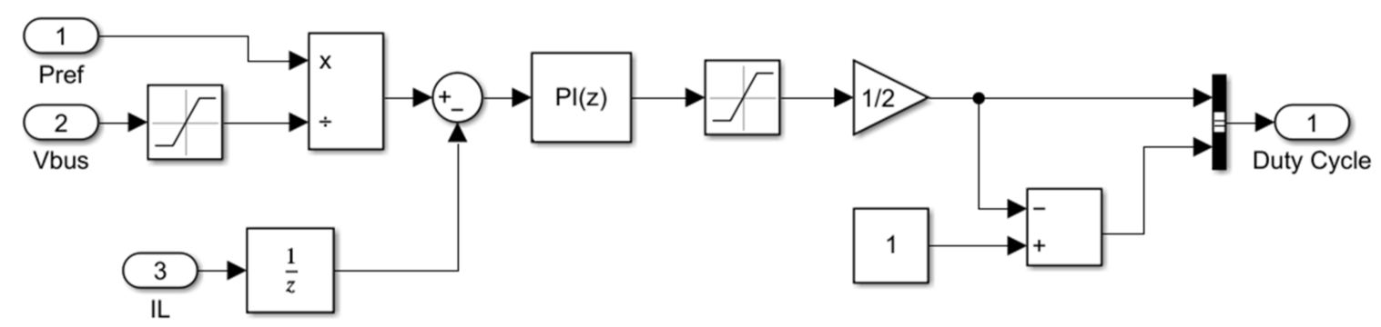
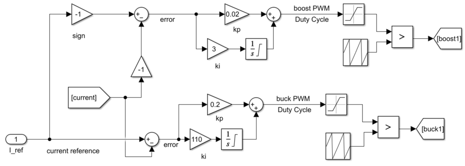
2.1.3. Modeling of DC-DC Converters

The DC-DC converter converts a certain DC power into a controllable DC power to meet the demand of the traction load. It cuts the constant DC voltage into form through a series of high and low pulse voltages, by the rapid on-and-off control of the switching components. Through the control of the duty cycle, the pulse widths of these pulses are changed in order to adjust the output. The average value of the pulse voltage that is passed by the output filter to obtain a voltage-controllable DC current, or voltage, depends on the required load. According to the proposed system shown in Figure 1, two types of DC-DC converters are adopted.

Unidirectional Converter

According to whether there is electrical isolation installed between the output end and the input end, the DC-DC converter can be divided into two types: the isolated DC-DC converter and the non-isolated DC-DC converter. Meanwhile, due to the function and circuit structure, they can be divided into step-down, step-up, up-down, etc. The terminal voltage of the fuel cell is very low, so the number of fuel cells needs to be connected in series and be parallel to obtain a fuel cell stack for the required power supply. The capacity of the stack depends on the number of fuel cells. Generally, in order to save the cost, this used fuel cell number should be reduced without affecting its performance, for instance, the output power and voltage. The bus voltage of a hybrid system is generally higher than the terminal voltage of the fuel cell. Therefore, the fuel cell must be boosted before being connected to the bus. Accordingly, the boost converter is adopted as its interface converter to meet the access requirements. The unidirectional DC-DC converter works in a constant current mode. Therefore, the proposed controller uses the ratio of the reference output power from the control system over the DC bus voltage as the reference output current of the converter. Then, using the inductor output current at the end of the converter, this reference current is compared to extract the error and send it to the PI controller to obtain a suitable duty cycle. Finally, input PWM signals are extracted to switches in order to regulate the converter as shown in Figure 4.

Bidirectional Converter

The energy storage system plays a role in balancing the power and bus voltage for the FCHPS. When the fuel cell output power is greater than the load demand power, the energy storage device balances the voltage by absorbing the excess power. When the system provides insufficient energy, the energy storage device outputs power to support the load. Therefore, the energy storage system is both a load and a power source, so its current needs to flow in both directions. In order to achieve this purpose, the commonly required converter is the bidirectional DC-DC converter, which can transfer energy in the power conversion system. Corresponding to the bidirectional DC-DC converter working in Buck and Boost working modes, the bidirectional converter can stabilize the DC bus voltage in order to reduce the voltage fluctuation and improve the stability of the system. The designed bidirectional DC-DC converter model works in a single-loop control mode, which is the current control loop. When the load needs a lithium battery to provide energy, the converter is working in constant voltage output mode. It compares the DC bus-side current as a reference with the battery-side current to get the error. Then, this error is sent into the PI controller to generate a suitable duty cycle as the input signal of IGBT to achieve the purpose of stabilizing the bus voltage of the bidirectional converter. The controller of a bidirectional DC-DC converter has two parts: one is a boost for discharge in which the current is positive, and the other is a buck for charge in which the current is negative. To output the right duty cycle, the logic block is needed to compare zero with the reference current. When the lithium battery is in a low SOC state, the DC bus charges the lithium battery to maintain the SOC within a certain range. By using the controller model in a reference study and to rewrite parameters, the controller block model and logic block are designed. The proposed control block model of the bidirectional DC-DC converter is shown in Figure 5.

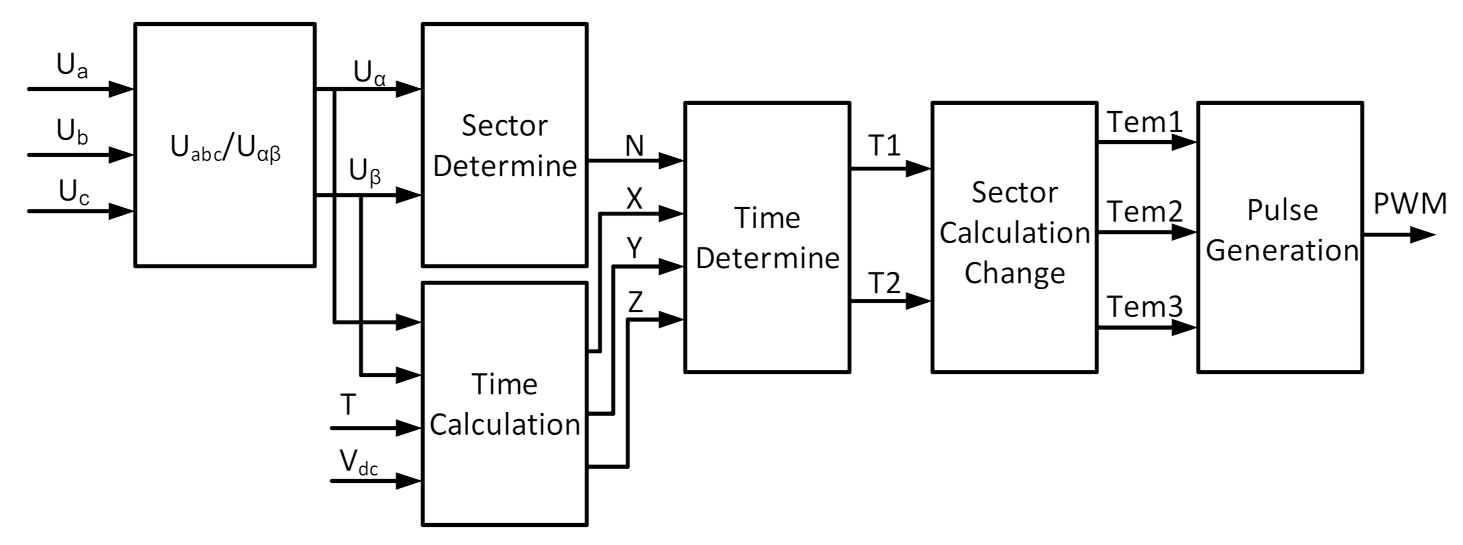
2.1.4. Modeling of DC-AC Converters

The traction inverter is the main component of the fuel cell hybrid power system. The study of the inverter structure and its control is one of the most important steps when the traction motor of the hybrid power system is used as a load. The inverter circuit generally includes a control and drive circuit, a detection and protection circuit, and the main circuit for power conversion and control. The voltage source inverter is suitable for loads with a large harmonic current impedance. When the load has a larger inductance, the harmonic current will decrease, and the waveform of the current will be closer to sinusoidal. The DC side capacitor has the ability to maintain voltage stability, which can improve the efficiency of the inverter. At present, voltage-type inverters have been widely used. Two types of popular topologies, half-bridge and full-bridge, can be considered for the proposed system. The half-bridge inverter has a simple structure and is low-cost under the same power conditions, but its DC-side voltage utilization rate is low, and it contains the output of large harmonic content. Compared with the half-bridge inverter, the full-bridge inverter is able to output the larger power, and the harmonics inside the output waveform are low. In summary, for the proposed system, two paralleled voltage-type full-bridge inverters are adopted. In order to control the inverter, space vector pulse width modulation (SVPWM) control technology, which is widely used in AC drives of asynchronous motors, is adopted. The basic control scheme is shown in Figure 6. Inverse Clark transformation is firstly used to convert three-phase voltage to Vα and Vβ, then the signals transferred to the sector determine the block to realize the sector. As shown in the figure, there are 6 sectors. Not only the period of PWM and Vdc, but also Vα and Vβ are the input of the Time Calculation block. This block outputs the time signal XYZ, which represents different sectors of SVPWM. X, Y, and Z are sent into the Time Determine block, and finally, time signals T1 and T2 are generated. These two signals are injected into the Sector Calculation Change block to output Tem1, Tem2, and Tem3 time signals for the PWM waveform.

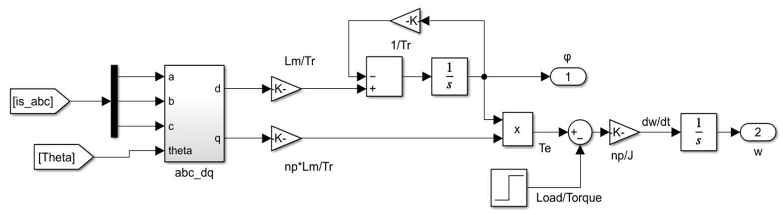
2.1.5. Modeling of Traction Motors

As a vital part of the hybrid power system, the asynchronous traction motor itself is a high-order, nonlinear, and strongly coupled multivariable system. Its static and dynamic characteristics, as well as control strategies, are especially complex. In order to make the asynchronous motor as a load of a designed hybrid power system and get an accurate response, it is necessary to study the foundational mathematical model of the asynchronous motor and its control method. The asynchronous motor mathematical model consists of voltage functions, flux functions, and torque functions. The voltage function of the asynchronous motor is as Equation (9):
u s a u s b u s c u r a u r b u r c u = R s 0 0 0 0 0 0 R s 0 0 0 0 0 0 R s 0 0 0 0 0 0 R r 0 0 0 0 0 0 R r 0 0 0 0 0 0 R r R i s a i s b i s c i r a i r b i r c i + d d t ψ s a ψ s b ψ s c ψ r a ψ r b ψ r c ψ
where usa, usb, usc are the terminal voltage of stator windings, ura, urb, urc are the terminal voltage of rotor windings, isa, isb, isc are the terminal current of stator windings, ira, irb, irc are the terminal current of rotor windings, Ψsa, Ψsb, Ψsc are the terminal flux of stator windings, Ψra, Ψrb, Ψrc are the terminal flux of rotor windings, and RS and Rr are the resistance of stator and rotor windings. The flux-linkage of each winding is the summation of its self-inductance and the mutual induction of other windings and can be calculated as Equation (10):
ψ s a ψ s b ψ s c ψ r a ψ r b ψ r c Ψ = L A A L A B L A C L A a L A b L A c L B A L B B L B C L B a L B b L B c L C A L C B L C C L C a L C b L C c L a A L a B L a C L a a L a b L a c L b A L b B L b C L b a L b b L b c L c A L c B L c C L c a L c b L c C L i s a i s b i s c i r a i r b i r c i
where LAA, LBB, LCC, Laa, Lbb, Lcc are dedicated to the self-inductance of each winding, and LAB, LAC, LAa, LAb, LAc are mutual inductance between windings. The electromagnetic torque of a motor can be obtained by the law of conservation of energy. According to the principle of energy conversion, in a multi-phase winding motor, the magnetic energy equation can be calculated as Equation (11):
W m = 0.5 i T L i
Meanwhile, the electromagnetic torque equation can be extracted as Equation (12):
T e = n p d W m d θ
where np is the number of pole pairs. With the assumption of neglecting the friction and torsional elasticity in the transmission mechanism of the electric drive system, the torque balance equation of the asynchronous motor is as Equation (13):
T e T L = J   d ω r n p d t + D n p ω r
where TL is load torque, J is rotational inertia, and D is damping coefficient. These equations constitute a multi-variable nonlinear mathematical model of a three-phase asynchronous motor under a constant torque load. It is complicated to directly calculate and analyze them. Therefore, converting the mathematical model of the asynchronous motor in a two-phase rotating coordinate system, with the rotation speed of ωe, after adopting Clark transformation and then using Park transformation, the electromagnetic matrix equation of the asynchronous motor can be expressed as Equation (14):
ψ s d ψ s q ψ r d ψ r q = L s 0 L m 0 0 L s 0 L m L m 0 L r 0 0 L m 0 L r i s d i s q i r d i r q
The voltage equations of rotor and stator resistance in the stationary frame can be expressed as Equation (15):
u s d u s q u r d u r q = R s + L s p ω e L s L m p ω e L m ω e L s R s + L s p ω e L m L m p L m p ω s L m R r + L r p ω s L r ω s L m L m p ω s L r R r + L r p i s d i s q i r d i r q

Space Vector Control Based on Rotor Field Orientation Control (FOC)

Vector control follows the fundamentals of producing equivalent magnetomotive power, changing over a three-stage fixed arrange framework to a two-stage fixed facilitate framework, and afterward to a two-stage turning coordinate framework, which totally decouples the stator current excitation part and force part; overall, they are spatially opposite to one another. The stator current is not proportional to the electromagnetic torque. There is an active component to generate the torque and an excitation component to produce magnetic fields. If the vector relationship of the asynchronous motor is transformed to the synchronous rotation dq coordinate system, and the d axis is oriented along the direction of the rotor flux linkage, then, the stator current of the asynchronous motor can be decomposed into an excitation current component and a torque current component, along the d axis and along the q axis, and rotating with them. Therefore, the synchronous rotating coordinate system turns the vector control into the scalar control, and the rotor field-oriented strategy decouples the nonlinearity of the concerned system in order to improve the dynamic performance and reduce the complexity. The voltage matrix under the dq coordinate can be written as Equation (16):
u s d u s q 0 0 = R s + L s p ω e L s L m p ω e L m ω e L s R s + L s p ω e L m L m p L m p 0 R r + L r p 0 ω s L m 0 ω s L r R r i s d i s q i r d i r q
Combining the flux equation, the stator d-axis excitation current and q-axis torque current are obtained, and the expression of the electromagnetic torque Te in the steady-state can be calculated as Equation (17):
i s d = ω s T r L m ψ r i s q = 1 + T r p L m ψ r T e = n p L m L r ψ r i s q i s d = ω s T r L m ψ r i s q = 1 + T r p L m ψ r T e = n p L m L r ψ r i s q
where Tr = Lr/Rr is the time constant of the rotor. By observing the equations of (17), the electromagnetic torque is determined by stator current isq and rotor flux Ψr. The rotor flux Ψr is controlled by isd, so the electromagnetic torque can be regulated and controlled indirectly by the current isq. With this relationship and the above mathematical equations, the three-phase asynchronous motor can be modeled as shown in Figure 7 converting three-phase currents to dq coordinate systems by abc/dq block.
Under the steady-state condition, the rotor voltage equation can be written as Equation (18):
u s d = R s + σ L s p i s d σ L s ω e i s q u s q = R s + σ L s p i s q + σ L s ω e i s d + L m L r ψ r ω e
where σ is the leakage coefficient. The Equation (18) indicates that the stator current of both isd and isq influences the stator voltage. To decouple the stator voltage with the current, a transfer function with stator resistance and inductance can be utilized. Therefore, the reference stator current equation could be written as Equation (19):
i s q * = T e * L r n p L m ψ r * i s d * = ψ r * L m
Using the reference current in Equation (19), the reference voltage equation can be rewritten as Equation (20):
u s d * = R s i s d * σ L s ω e i s q * u s q * = R s i s q * + σ L s ω e i s d *
After calculating the relative parameters of the reference stator current and the voltage through the above mathematical equations, there are sufficient data for voltage vector control modeling.

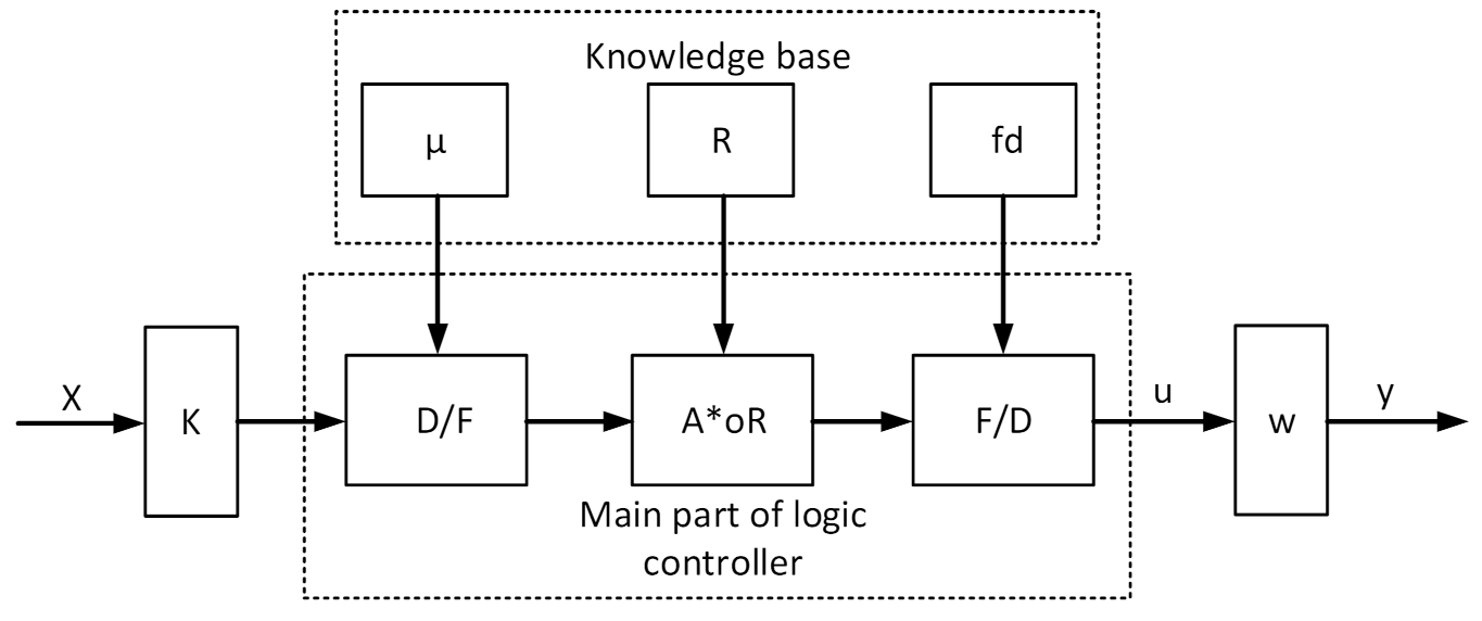
3. Fuzzy Logic-Based Modified Control Energy Management Strategy

The energy management method of the hybrid power system allocates load demand power among different power sources reasonably. Generally, the design principle is to minimize fuel consumption ensuring vehicle performance, while also taking into account the auxiliary energy equipment’s service life. When the vehicle is braking, energy can be recovered through the energy management strategy, so as to continue to provide the required power. This section studies the proposed fuzzy logic-based energy management system that is proposed. The MFL-EMS uses the designed rules to follow the required power; with more rules, the result becomes more precise, so as to allocate power reasonably. According to the different sources of fuzzy control rules, fuzzy controllers are mainly divided into Mamdani type and TS type. This paper only adopts the Mamdani-type fuzzy controller to design the fuzzy logic energy management strategy of FCHL, so the principle of the Mamdani type will be briefly introduced in the next sections. For fuzzy controllers, the most widely used type in the engineering area is the structure of two-dimensional input and one-dimensional output (shown in Figure 8), which mainly includes a quantization factor module, a fuzzy module, an approximate reasoning module, a clarification module, and a scale factor module.

3.1. Quantization Factor

The beginning of the left part in Figure 8 is a quantization factor module composed of a numerical vector, which performs a proportional transformation on the real value signal input to the fuzzy controller, which is the input interface of the fuzzy controller. The input signal vector of the fuzzy controller is X, each component is a continuous and real number obtained by sampling or calculation. Assuming that the component of X is xi, and belongs to Mi = [−mi, mi], then M is the physical theory domain of xi. The input of continuous real number components to the fuzzy controller needs to be fuzzified and mapped to the corresponding fuzzy subset. Suppose the domain of the fuzzy subset Aik (k = 1,2,3…n) corresponding to the component x of X after being fuzzified is Ni = [−ni, ni], then Ni is the fuzzy domain of xi. In most cases, the physical theory domain of the input of the fuzzy controller is different from the fuzzy theory domain, so the coefficient transformation needs to be performed through the quantization factor module.
It is known that the physical theory domain of component xi of the input signal vector Xi is Mi = [−mi, mi], and its fuzzy theory domain is Ni = [−ni, ni], so the definition of the transform coefficient k from M to N as the quantization factor is as Equation (21):
k i = n i m i
For the proposed control system, the necessary footing force of the locomotive required fuel cell power and the battery condition of charge SOC are chosen as the information factors of the fluffy rationale regulator, and the reference electrical power signal of the energy unit side DC-DC converter of the power device is chosen as the yield variable of the fluffy rationale regulator. In the present circumstance, the double information and single yield fluffy are taken on to execute the fluffy rationale energy of the executive’s methodology. According to the technical parameters of each component of the fuel cell hybrid electric vehicle, the domains of input and output variables are: fuel cell power belongs to [0–3 × 10⁵] W, SOC belongs to [0–100]%, Pref belongs to [0–3 × 10⁵] W, so the corresponding values of the quantization factor are as k 1 = 1 3 × 10 5 , k 2 = 1 100 . Therefore, the fuzzy domain of the input and output of the fuzzy logic controller is [0, 1].

3.2. Scale Factor

As shown in Figure 8, the rightmost is the scale factor module composed of the coefficient w. It mainly realizes the consistent transformation between the real-valued physical theory domain and the physical theoretical domain, which is required by the actuator after the clarification processing. Assuming that the physical theory domain of the output u after clarification processing is P = [−p, p], the physical theory domain of the input quantity y required by the actuator is Q = [−q, q], then the physical theory domain p to the transformation coefficient of the physical theory domain q is called the scale factor as Equation (22):
w = q p
Considering the fuel cell power range, the corresponding value of the scale factor for the proposed system is w = 3 × 10 5 .

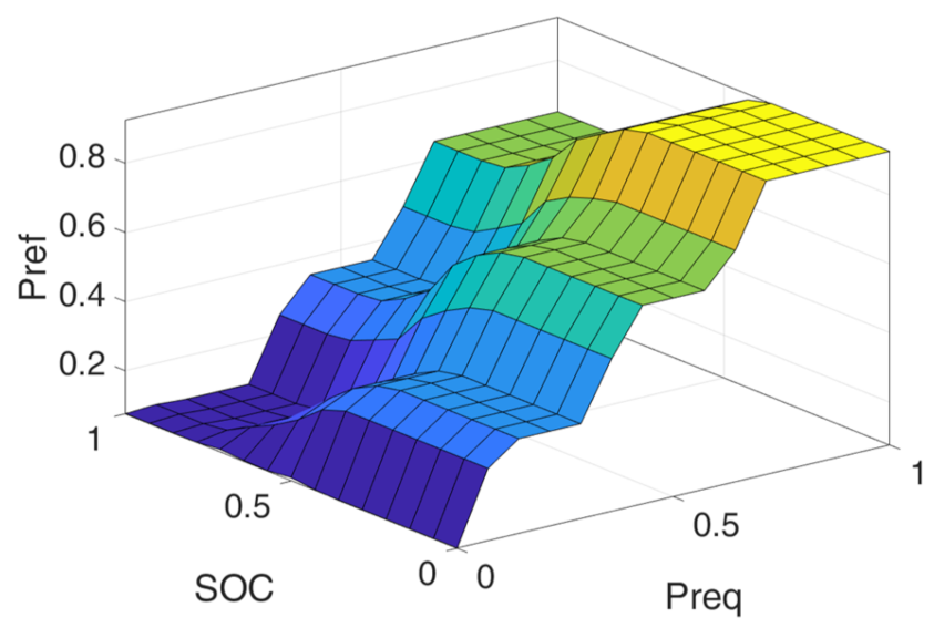
3.3. Approximate Reasoning and Clarification
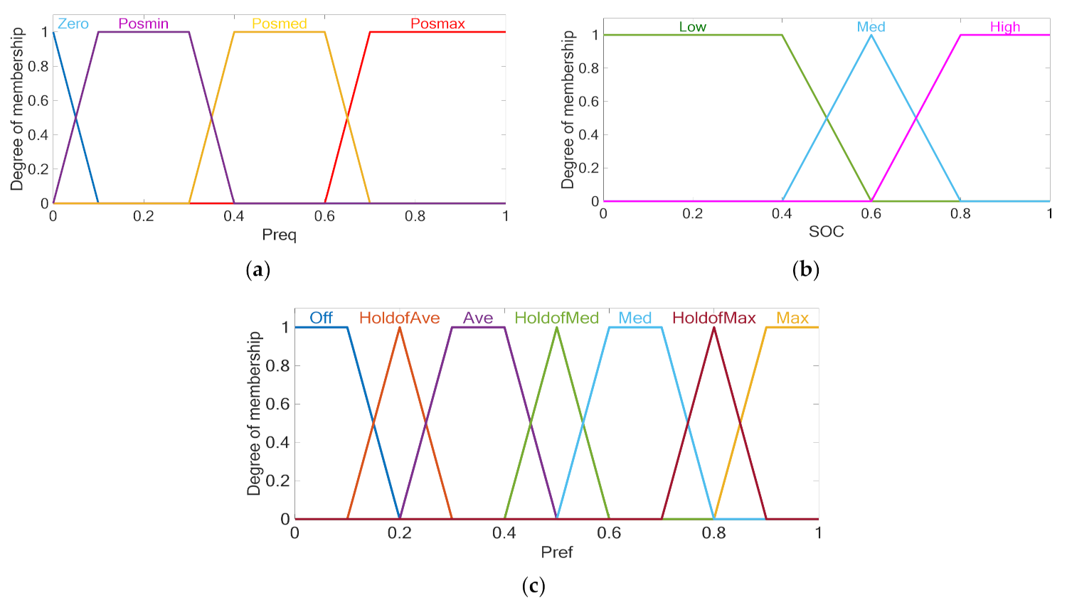
The modules named A*oR and R are the approximate reasoning module and the control rule module of the fuzzy logic controller, respectively, which are the core links to realize the fuzzy controller. Fuzzy control rules are composed of fuzzy conditional sentences, which are composed of a series of ‘if … then …’ fuzzy implication relations. Fuzzy conditional sentences are generally obtained through experimental observations or based on the designer’s experience. They are the key and the basis for approximate reasoning. In essence, a fuzzy implication relationship is a fuzzy control rule. After the quantization factor and the fuzzification process, the input signal vector is mapped into a fuzzy vector, and the corresponding fuzzy set is output according to the approximate reasoning rule. In Figure 8, the F/D and fd modules are the clarification module and the clarification algorithm module. The main function is to equate the fuzzy set output by approximate reasoning to a clear real value. The principle of the clarification method is to use a certain clear and real value in the fuzzy domain to represent the fuzzy set. Generally, it only needs to satisfy the evidence reasonably, and the calculation is convenient and continuous.

3.4. Fuzzification

In Figure 8, the D/F and μ blocks are fuzzy modules and membership function information modules, respectively. The fuzzification processing is mainly to obtain the membership degree of each real-valued component after the quantization factor processing for each fuzzy subset. First of all, in order to make each input variable xi fuzzy, it is necessary to determine the number of fuzzy subsets covering the fuzzy domain Ni. Secondly, to determine the fuzzy subset distribution covering the entire fuzzy domain, three characteristics of completeness, consistency, and interaction must be considered. Finally, the membership function of each fuzzy subset is determined. The discreteness or continuity of the fuzzy domain determines the selection of the membership function. Commonly used types of membership functions are Z-shaped, triangle-shaped, bell-shaped, Gauss-shaped, trapezoidal, and S-shaped. There is no standard for the selection and design of the membership function, which mainly depends on the situation of the controlled object and the personal habits of the designer. Generally speaking, close to the system equilibrium point, choosing a steep membership function to improve control sensitivity and move away from the system equilibrium point, and choosing a gentle membership function to speed up the adjustment time, is appropriate. The fuzzy subset of the fuel cell power of the locomotive is divided into zero, positive small, positive median, and positive big, using symbols to indicate {Zero, Posmin, Posmed, Posmax}. The fuzzy subset of the battery state of charge SOC is divided into low, medium, and high, using symbols denoted as {Low, Med, High}. Furthermore, the fuzzy subset of the reference electrical power signal of the fuel cell side DC-DC converter is divided into off, off–average hold, average, average–medium hold, medium, medium–maximum hold, and maximum. It is represented by symbols as {Off, HoldofAve, Ave, HoldofMed, Med, HoldofMax, Max}. A non-uniformly distributed membership function is used to improve the sensitivity of fuzzy control. The proposed fuzzy distribution and membership functions of input and output variables are shown in Figure 9.
The control rules of the fuzzy logic energy management strategy are defined according to the following principles:
  • Ensure the power demand of the hybrid locomotive;
  • Reduce the dynamic load of the fuel cell and optimize its working performance;
  • Maintain the state of charge of the battery near the expected value, and, at the same time, make full use of the energy stored and absorbed by the battery, reduce fuel costs, and improve the economy of the hybrid locomotive.
The established fuzzy control rules are shown in Table 1. Among them, the basic rule of fuzzy inference is “if A and B, then U”, and all of the control rules are summarized based on actual operating experience. The proposed fuzzy logic energy management strategy rules are shown in Figure 10.
In order to ensure that the fuel cell is always in the normal working area, the reference power of the fuel cell side of the converter should be restricted as Equation (23):
P r e f f c m a x f c m i n
where Pref is the reference power of the fuel cell side converter, Pfcmin is the minimum output power of the fuel cell, and Pfcmax is the maximum output power of the fuel cell.

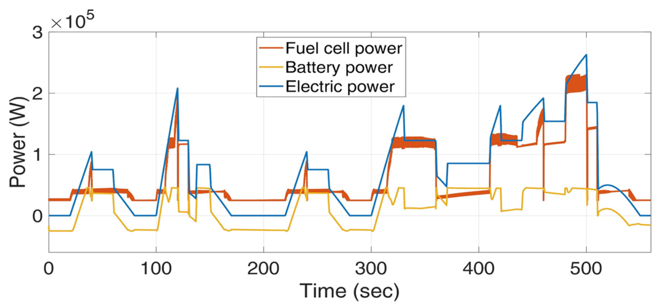
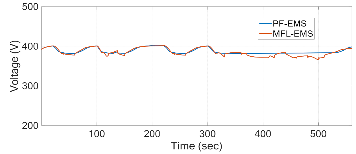
4. Results and Discussion

For the proposed FCHL in this paper, such a system is created: the fuel cell side DC-DC converter with lithium battery side bidirectional DC-DC topology is adopted. The DC bus is connected to 2 traction motors through two sets of parallel traction inverters.
The parameter of each component is confirmed and stetted based on the data illustrated in Table 2. The FCHPS model with the control of traction motors is executed in a MATLAB/SIMULINK simulation platform. According to the locomotive’s continuous running speed, acceleration, grade ability, and other performance indicators (shown in Table 3), the output power, peak power, rated torque, rated speed, and other related parameters of the motor under different working conditions can be calculated.
In order to get the required power consumed by the hybrid locomotive in the proposed simulation model of the FCHPS, the driving cycle should be generated. This paper assumes a section of locomotive driving conditions where the vehicle speed changes frequently because of the railway system’s inherent features. The main purpose is to investigate the correctness and effectiveness of the proposed energy management strategy under various power demand conditions. The considered driving cycle and demand for electrical power are shown in Figure 11. The maximum speed for the tramway line is considered 40 km/h.
Through adopting these driving features, the effectiveness of the proposed MFL-EMS for the fuel cell hybrid locomotive is evaluated and the simulation results are compared with the PF-EMS. In this context, the PF-EMS main situations are considered as the minimum fuel cell output power Pfcmin = 25 kW, the maximum fuel cell output power Pfcmax = 300 kW, the maximum dynamic changing rate of the fuel cell power as 50 kW/s, the upper limit of the battery state of charge SOCh = 80%, the lower limit of the battery state of charge SOCl = 40%, and the initial state of charge of the battery SOC = 70%. Figure 12 illustrates that the output power of the fuel cell is determined and distributed suitably by both powers following the energy management strategies, according to the required power profile of Figure 11. More specifically, it varies according to the requirements of the traction demand power of the vehicle, corresponding to the dedicated driving cycle for 560 s. As can be seen from the results of this figure, the proposed MFL-EMS reduces the dynamic load of the fuel cell and the sharp changes. Under hypothetical driving conditions and conventional PF-EMS, the FCHL adopts power following an energy management strategy with a hydrogen consumption of 0.05471 kg. However, the hydrogen consumption of the FCHL adopting the proposed MLF-EMS is 0.05370 kg. Compared with the conventional EMS, hydrogen consumption is reduced by 1.846%.
Figure 13 demonstrates the required power, fuel cell power, and battery power in the designed scenario for the proposed system. Based on this figure, the battery system can provide adequate power for the traction motor during acceleration. After a few moments, the fuel cell entered the cycle and charged the battery pack. The negative power area of the battery in the figure reveals this subject. To ensure fuel cell efficiency, it should be noted that battery and fuel cell rarely output power simultaneously. In addition to providing or absorbing power according to the energy distribution principle, the battery also works for the instantaneous change of load power.
As can be seen in this figure, when required power reaches the limitation of FC power during acceleration, the BESS supplies the rest of the power as the auxiliary source. During deceleration and braking, the BESS charges and absorbs the braking power. In other words, due to the slow dynamic response time of the fuel cell, when the traction demand power increases instantaneously, the output power of the fuel cell cannot increase to the desired output value in a short time, so the battery provides this instantaneous power. Similarly, when the traction demand power instantaneously decreases, the output power of the fuel cell cannot be reduced to the set point value in a short time, so the battery absorbs this exceeding instantaneous power. Concentrating on the battery power profile shown in Figure 14, it can be seen that in the proposed MFL-EMS, the battery not only outputs or absorbs power according to the energy distribution principle of the control strategy, but also takes the responsibility for the instantaneous change of load power. Especially from 300 s, the changes in battery power reveal that the proposed MFL-EMS is more robust and accurate than PF-EMS. In other words, due to the dynamic limitations of the conventional method, the proposed method supplies the transient power demand successfully during sudden acceleration or braking of the tramway taking advantage of BESS. To compare the battery performance for both methods by evaluating Figure 15, it is obvious that the proposed MFL-EMS can maintain the state of charge (SoC) of the battery within the expected range, and the final state of charge of the battery is 63.9%. Assuming that after the driving condition is over, the battery is charged or discharged with rated power so that its final state of charge is the same as the PF-EMS. Under this condition, the final SoC of the battery is consistent, and the equivalent hydrogen consumption stored by the battery is 0.0006 kg. Considering the final state of charge of the battery, the total converted hydrogen consumption under the MFL-EMS is 0.0531 kg. Compared with the PF-EMS, the hydrogen consumption is reduced by 2.943%. The difference after 300 s in SoC reveals that the proposed MFL-EMS adopts BESS more to compensate and supply the transient states during sudden acceleration or braking of the tramway.
The BESS voltage during the drive cycle is shown in Figure 16. It can be easily observed that the DC bus voltage is kept constant around the reference amount (400 V) under the proposed and traditional method. However, comparing the performance of the two methods, the battery output voltage with MFL-EMS tends to be steeper than the one with PF-EMS for transient intervals, which reveals the proposed strategy’s robustness, and it can make better use of battery power. The results confirm the efficiency of the proposed PI control.
Considering fuel cell voltage and current profile in Figure 17, it can be seen that under the designed MFL-EMS, the output voltage and output current of the fuel cell and battery are within the rated range, and the maximum or minimum working points are avoided. In other words, the transient situations and quick changes in voltage and currents due to the time-varying features of the tramway have been controlled and damped by the proposed MFL-EMS. As shown in Figure 17, the maximum voltage drop and current overvoltage, which happens in the high power consumption mode of the tramway (110 s and 500 s), have been decreased by about 5% and 12%, respectively. Overall, the proposed MFL-EMS has the ability to meet the power demand of FCHL, reduce the dynamic load of fuel cells, optimize the performance of fuel cells, and maintain the state of charge of the battery within the expected range. In addition, it can fully utilize the energy stored and absorbed by the battery, reducing the consumption of hydrogen fuel and improving the fuel economy of the vehicle.
In addition, the proposed MFL-EMS has the capacity to satisfy the force need of power modules over electric trains, diminish the unique heap of energy units, advance the exhibition of energy components, and keep up with the condition of charge of the battery inside the normal situation. Moreover, it can completely use the energy put away and consumed by the battery, decreasing the utilization of hydrogen fuel and further developing the mileage of the vehicle.

5. Conclusions and Future Work

As one of the most environmentally friendly green energy sources today, fuel cells are used as the main power source of the FCHPS. FCHLs with a power system composed of fuel cells and auxiliary energy sources possess high efficiency and environment-friendly characteristics, and they have received extensive attention to be a new type of rail transportation. This paper focuses on the study of FCHPS for locomotives considering the control of traction motors, the structure design, parameter matching, and energy management methods of the system. In this context, the optimal topology of the FCHPS for the locomotive is proposed by calculating the parameters of the entire locomotive, the input power required by the traction inverter, and the parameter configuration of the traction motor under the three different operating states of the locomotive; at the maximum speed, the maximum grade and maximum acceleration.Then the parameters of the fuel cell and the lithium battery are combined. Finally, the conventional PF-EMS and proposed MFL-EMS are executed as energy management strategies. Through the analysis of the simulation results, the effectiveness of the two energy management methods is further verified. The proposed MFL-EMS is executed by considering the locomotive demanded traction power and battery state of charge SOC as input parameters, and the DC-DC converter reference power signal as an output, and then by finalizing corresponding fuzzy control rules based on the characteristics of the locomotive under study. According to the results, adopting the proposed MFL-EMS in comparison to the traditional PF-EMS, reduced the hydrogen consumption by 2.943%. Comparing the battery output voltage, it is confirmed that with MFL-EMS, it tends to be steeper than the one with PF-EMS showing the proposed strategy’s robustness. Overall, the obtained results revealed an improved performance in terms of power distribution as well as SOC, which means less hydrogen consumption and therefore a more economical solution. However, due to the nonlinear and time-varying features of railway systems which need fast power demand fluctuations in real driving cycles, a trade-off between the energy efficiency and dynamic performance of EMSs and the lifetime of the ESS must be considered. In this context, adopting and analyzing a robust signal processing method as a future work can be a promising solution to address transients and improve MFL-EMS performance.

Author Contributions

In preparation of this paper, H.J.K. and H.L. did the methodology, data curation, software-based simulations, and writing—original draft, M.B. and D.Z. did the validation, visualization, and the resources and funding acquisition; together with editing, and supervision. All authors have read and agreed to the published version of the manuscript.

Funding

This research received no external funding.

Institutional Review Board Statement

Not applicable.

Informed Consent Statement

Not applicable.

Data Availability Statement

Not applicable.

Conflicts of Interest

The authors declare no conflict of interest.

Nomenclature

Acronyms
BESSbattery energy storage system
BNSFBurlington North America the Santa Fe
FCHLfuel cell hybrid locomotive
MFL-EMSfuzzy logic-based energy management system
PF-EMSpower flow energy management system
FCSfuel cell stack
EMSenergy management strategy
FRCfluffy rationale control
ECMS_DFCEMS technique dependent on dynamic following coefficient
FCHPSfuel cell hybrid power system
PEMFCproton exchange membrane fuel cell
SOCState of charge
SVPWMspace vector pulse width modulation
FOCfield orientation control
Indexes
Vs [V]stack voltage/output voltage
Nnumber of series-connected cells in the stack
ENernst [V]reversible fuel cell voltage
Vact [V]voltage drop at the lower currents
Vcon [V]voltage drop at higher currents
Vohmic [V]voltage drop at the intermediate currents
Td [K]cell operating temperature in Kelvin
PH2 [Pa]partial pressures of hydrogen
PO2 [Pa]partial pressures of oxygen
FFaraday constant
Rgas constant
A [mV/decade]Tafel slope
io [A]exchange current density
ifc [A]fuel cell current
rohm [Ω]equivalent internal resistance of the fuel cell
I [A]output current of the battery
Q [Ah]maximum capacity of the battery
Vdc [V]DC bus voltage of converter
usa, usb, usc [V]terminal voltage of stator windings
ura, urb, urc [V]terminal voltage of rotor windings
isa, isb, isc [A]terminal current of stator windings
ira, irb, irc [A]terminal current of rotor windings
Ψsa, Ψsb, Ψsc [A]terminal flux of stator windings
Ψra, Ψrb, Ψrc [Wb]terminal flux of rotor windings
Wm [J]magnetic energy
Te [N·m]electromagnetic torque
npnumber of pole pairs
TL [N·m]load torque
J [kg·m2]rotational inertia
D [N s/m]damping coefficient
ωe [rad/s]rotation speed
isq [A]stator current in q axis
isd [A]stator current in d axis
Xinput signal vector of the fuzzy controller
Mphysical theory domain of input signal
Aikdomain of the fuzzy subset
Nidomain of the fuzzified fuzzy subset
kiquantization factor
Pref [W]reference power of the fuel cell
wscale factor
A*o Rapproximate reasoning module
F/Dclarification module
D/Ffuzzy module
μmembership function information module
Pfcmin [W]minimum output power of the fuel cell
Pfcmax [W]maximum output power of the fuel cell
SOCh [%]upper limit of the battery state of charge
SOCl [%]lower limit of the battery state of charge

References

  1. Craven, N.; Orsini, R.; Ciuffini, M.; Arena, D. UIC Low Carbon Rail Challenge. In Technical Report; United Nations Climate Summit: New York, NY, USA, 2014. [Google Scholar]
  2. Brenna, M.; Foiadelli, F.; Kaleybar, H.J. The Evolution of Railway Power Supply Systems Toward Smart Microgrids: The concept of the energy hub and integration of distributed energy resources. IEEE Electrif. Mag. 2020, 8, 12–23. [Google Scholar] [CrossRef]
  3. Miller, A.R.; Peters, J.; Smith, B.E.; Velev, O.A. Analysis of fuel cell hybrid locomotives. J. Power Sources 2006, 157, 855–861. [Google Scholar] [CrossRef]
  4. Sarma, U.; Ganguly, S. Modelling and Cost-Benefit Analysis of PEM Fuel-Cell-Battery Hybrid Energy System for Locomotive Application. In International Conference on Technologies for Smart City Energy Security and Power: Smart Solutions for Smart Cities, ICSESP 2018—Proceedings; IEEE: Piscataway, NJ, USA, 2018; pp. 1–5. [Google Scholar]
  5. Sun, L.; Chan, C.C.; Liang, R.; Wang, Q. State-of-Art of Energy System for New Energy Vehicles. In Proceedings of the 2008 IEEE Vehicle Power and Propulsion Conference, VPPC 2008, Harbin, China, 3–5 September 2008. [Google Scholar]
  6. Jafari Kaleybar, H.; Fazel, S.S. Three-Port Multifunctional Railway Power Conditioner Integrated with Energy Storage Systems for Regenerative Braking Energy and Power Quality Control. Int. J. Railw. Res. 2020, 7, 35–43. [Google Scholar]
  7. Ahmadi, M.; Jafari Kaleybar, H.; Brenna, M.; Castelli-Dezza, F.; Carmeli, M.S. Integration of Distributed Energy Resources and EV Fast-Charging Infrastructure in High-Speed Railway Systems. Electronics 2021, 10, 2555. [Google Scholar] [CrossRef]
  8. Khodaparastan, M.; Mohamed, A.A.; Brandauer, W. Recuperation of Regenerative Braking Energy in Electric Rail Transit Systems. IEEE Trans. Intell. Transp. Syst. 2019, 20, 2831–2847. [Google Scholar] [CrossRef] [Green Version]
  9. Miller, A.R.; Hess, K.S.; Barnes, D.L.; Erickson, T.L. System Design of a Large Fuel Cell Hybrid Locomotive. J. Power Sources 2007, 173, 935–942. [Google Scholar] [CrossRef]
  10. Ahmadi, S.; Bathaee, S.M.T. Multi-Objective Genetic Optimization of the Fuel Cell Hybrid Vehicle Supervisory System: Fuzzy Logic and Operating Mode Control Strategies. Int. J. Hydrogen Energy 2015, 40, 12512–12521. [Google Scholar] [CrossRef]
  11. Chen, Q.; Gao, L.; Dougal, R.A.; Quan, S. Multiple Model Predictive Control for a Hybrid Proton Exchange Membrane Fuel Cell System. J. Power Sources 2009, 191, 473–482. [Google Scholar] [CrossRef]
  12. Miller, A.R.; Hess, K.S.; Erickson, T.L.; Dippo, J.L. Demonstration of a Hydrogen Fuel-Cell Locomotive. In Proceedings of the Locomotive Maintenance Officers Association conference, Chicago, IL, USA; 2010; pp. 1–6. [Google Scholar]
  13. China Rolled Out Its First Self-Developed Hydrogen Fuel Cell Hybrid Locomotive. Available online: http://www.ecns.cn/news/sci-tech/2021-01-28/detail-ihafywhr7620669.shtml (accessed on 24 June 2022).
  14. Fadel, A.; Zhou, B. An Experimental and Analytical Comparison Study of Power Management Methodologies of Fuel Cell-Battery Hybrid Vehicles. J. Power Sources 2011, 196, 3271–3279. [Google Scholar] [CrossRef]
  15. Xie, C.; Ogden, J.M.; Quan, S.; Chen, Q. Optimal Power Management for Fuel Cell-Battery Full Hybrid Powertrain on a Test Station. Int. J. Electr. Power Energy Syst. 2013, 53, 307–320. [Google Scholar] [CrossRef]
  16. Xie, C.; Xu, X.; Bujlo, P.; Shen, D.; Zhao, H.; Quan, S. Fuel Cell and Lithium Iron Phosphate Battery Hybrid Powertrain with an Ultracapacitor Bank Using Direct Parallel Structure. J. Power Sources 2015, 279, 487–494. [Google Scholar] [CrossRef]
  17. Bassam, A.M.; Phillips, A.B.; Turnock, S.R.; Wilson, P.A. An Improved Energy Management Strategy for a Hybrid Fuel Cell/Battery Passenger Vessel. Int. J. Hydrogen Energy 2016, 41, 22453–22464. [Google Scholar] [CrossRef] [Green Version]
  18. Hong, Z.; Zhu, Y.; Shang, W.; Li, Q.; Chen, W. Research of Energy Management Strategy for Fuel Cell/Battery Hybrid Locomotive. In Proceedings of the 2017 IEEE Transportation Electrification Conference and Expo, Asia-Pacific, ITEC Asia-Pacific, Harbin, China, 7–10 August 2017. [Google Scholar]
  19. Peng, H.; Chen, Y.; Chen, Z.; Li, J.; Deng, K.; Thul, A.; Löwenstein, L.; Hameyer, K. Co-Optimization of Total Running Time, Timetables, Driving Strategies and Energy Management Strategies for Fuel Cell Hybrid Trains. eTransportation 2021, 9, 100130. [Google Scholar] [CrossRef]
  20. Sarma, U.; Ganguly, S. Determination of the Component Sizing for the PEM Fuel Cell-Battery Hybrid Energy System for Locomotive Application Using Particle Swarm Optimization. J. Energy Storage 2018, 19, 247–259. [Google Scholar] [CrossRef]
  21. Wang, Z.; Xie, Y.; Zang, P.F.; Wang, Y. Energy Management Strategy of Fuel Cell Bus Based on Pontryagin’s Minimum Principle. J. Jilin Univ. Eng. Technol. Ed. 2020, 50, 36–43. [Google Scholar]
  22. Song, K.; Wang, X.; Li, F.; Sorrentino, M.; Zheng, B. Pontryagin’s Minimum Principle-Based Real-Time Energy Management Strategy for Fuel Cell Hybrid Electric Vehicle Considering Both Fuel Economy and Power Source Durability. Energy 2020, 205, 118064. [Google Scholar] [CrossRef]
  23. Ajayan, S.; Immanuel Selvakumar, A. Metaheuristic Optimization Techniques to Design Solar-Fuel Cell-Battery Energy System for Locomotives. Int. J. Hydrogen Energy 2022, 47, 1845–1862. [Google Scholar] [CrossRef]
  24. Wang, W.; Qu, F.; Wang, Q.; Wu, C. Research on Energy Control Strategy of 4WD Hybrid Electric Vehicle Based on Fuzzy Control. In Proceedings of the 2018 2nd IEEE Advanced Information Management, Communicates, Electronic and Automation Control Conference, IMCEC 2018, Xi’an, China, 25–27 May 2018; pp. 1806–1811. [Google Scholar]
  25. Yuan, Z.; Li, H.; Yousefi, N. Optimal Hydrogen Consumption of Fuel Cell-Based Locomotive Using Speed Trajectory Optimization by Improved Pathfinder Algorithm. J. Clean. Prod. 2021, 278, 123430. [Google Scholar] [CrossRef]
  26. Shang, W.; Yu, S.; Zhang, G.; Li, Q.; Chen, W. Fuel Cell Hybrid Locomotive System Based on Equivalent Consumption Minimization Strategy. In Proceedings of the 2017 Chinese Automation Congress, CAC 2017, Jinan, China, 20–22 October 2017; pp. 2457–2461. [Google Scholar]
  27. Li, Q.; Chen, W.; Liu, Z.; Li, M.; Ma, L. Development of Energy Management System Based on a Power Sharing Strategy for a Fuel Cell-Battery-Supercapacitor Hybrid Tramway. J. Power Sources 2015, 279, 267–280. [Google Scholar] [CrossRef]
  28. Guaitolini, S.V.M.; Yahyaoui, I.; Fardin, J.F.; Encarnacao, L.F.; Tadeo, F. A Review of Fuel Cell and Energy Cogeneration Technologies. In Proceedings of the 2018 9th International Renewable Energy Congress, IREC 2018, Hammamet, Tunisia, 20–22 March 2018; pp. 1–6. [Google Scholar]
  29. Mo, Z.J.; Zhu, X.J.; Wei, L.Y.; Cao, G.Y. Parameter Optimization for a PEMFC Model with a Hybrid Genetic Algorithm. Int. J. Energy Res. 2006, 30, 585–597. [Google Scholar] [CrossRef]
  30. Isa, Z.M.; Nayan, N.M.; Arshad, M.H.; Kajaan, N.A.M. Optimizing PEMFC Model Parameters Using Ant Lion Optimizer and Dragonfly Algorithm: A Comparative Study. Int. J. Electr. Comput. Eng. 2019, 9, 5295–5303. [Google Scholar] [CrossRef]
  31. Barcellona, S.; Piegari, L. Lithium Ion Battery Models and Parameter Identification Techniques. Energies 2017, 10, 2007. [Google Scholar] [CrossRef] [Green Version]
  32. Oliveira, D.B.S.; Glória, L.L.; Kraemer, R.A.S.; Silva, A.C.; Dias, D.P.; Oliveira, A.C.; Martins, M.A.I.; Ludwig, M.A.; Gruner, V.F.; Schmitz, L.; et al. Mixed-Integer Linear Programming Model to Assess Lithium-Ion Battery Degradation Cost. Energies 2022, 15, 3060. [Google Scholar] [CrossRef]
Figure 1. The energy flow diagram of the proposed hybrid locomotive topology.
Sustainability 14 08336 g001
Figure 2. PEMFC equivalent circuit.
Sustainability 14 08336 g002
Figure 3. Equivalent circuit of the battery.
Sustainability 14 08336 g003
Figure 4. Boost DC-DC converter control block model.
Sustainability 14 08336 g004
Figure 5. Bidirectional DC-DC controller model.
Sustainability 14 08336 g005
Figure 6. SVPWM basic diagram.
Sustainability 14 08336 g006
Figure 7. Three-phase asynchronous motor model in the locomotive.
Sustainability 14 08336 g007
Figure 8. Structure of the fuzzy controller.
Sustainability 14 08336 g008
Figure 9. Fuzzy membership functions. (a) membership function of fuel cell power as input. (b) membership function of SOC as input. (c) membership function of reference power as output.
Sustainability 14 08336 g009
Figure 10. Fuzzy rules surface for the proposed control energy management strategy.
Sustainability 14 08336 g010
Figure 11. Driving cycle features of the locomotive in the proposed system. (a) Speed. (b) Required power.
Sustainability 14 08336 g011
Figure 12. Fuel Cell power with proposed MFL-EMS and conventional PF-EMS.
Sustainability 14 08336 g012
Figure 13. Power curves comparison of FCHL.
Sustainability 14 08336 g013
Figure 14. Battery power profile for FCHPS for proposed MFL-EMS and traditional method.
Sustainability 14 08336 g014
Figure 15. Battery SOC% in the FCHPS for proposed MFL-EMS and traditional method.
Sustainability 14 08336 g015
Figure 16. Battery voltage in the FCHPS for proposed MFL-EMS and traditional method.
Sustainability 14 08336 g016
Figure 17. Fuel cell voltage and current profile in FCHPS for proposed MFL-EMS and traditional method. (a) Voltage. (b) Current.
Sustainability 14 08336 g017
Table 1. The proposed fuzzy logic control rules.
SOCPreq
ZeroPosminPosmedPosmax
LowHold of AveAveMedMax
MedOffHold of AveHold of MedHold of Max
HighOffOffAveMed
Table 2. Parameters of proposed FCHPS.
ParameterValue
Fuel cellType HD6
Nominal power (kW)300 kW
Rated working efficiency55%
Fuel/oxidantHydrogen/Air
MotorNominal/maximum power (kW)150/300
Nominal/maximum speed (rpm)1500/3200
Maximum traction torque (n.m)430
Maximum braking torque (n.m)550
No-load current67 A
BatteryTypeLithium-ion
Rated Capacity (Ah)120
Maximum discharging rate (C)5
Internal impedance (mΩ)35
Rated voltage (V)380
Table 3. Parameters of the proposed locomotive.
ParameterValueParameterValue
Vehicle Mass45 tAxleB-B
Maximum Speed70 km/hMaximum Gradient6.50%
Maximum Acceleration1 m/s2Maximum Grade Speed30 km/h
Inertia0.1Gravitational Acceleration9.8 N/kg
Critical Speed30 km/hTransmission System Efficiency0.95
Davis Coefficient A2.591Traction Inverter Efficiency0.95
Davis Coefficient B0.00078Davis Coefficient C0.0911
Publisher’s Note: MDPI stays neutral with regard to jurisdictional claims in published maps and institutional affiliations.

