Abstract
The DR-HVDC (Diode rectifier-based HVDC) transmission topology was recently proposed for integration on large offshore wind farms due to its low investment cost and high reliability. To further reduce the investment, a DC collection topology based on the series-connected diode rectifiers (DR) is proposed, where no offshore platform is needed. However, units of series-connected topology (SCU) show coupling issues, such as overvoltage, energy curtailment, and fault isolation. First, the coupling mechanism is analyzed, and a suitable operation mode for SCUs is selected to ensure the safe operation of the DC system. Then, the linear relationship of active power and output DC current and DC voltage of SCUs is analyzed, and a novel coordinate control strategy for DC wind farms is proposed, where an onshore converter adapts a DC current controller and wind turbines adapt a mediate output voltage control strategy. The mediate output voltage control strategy includes a triple loop with power loop, mediate output voltage loop, and current loop. Also, the DC open line fault, DC grounding fault, and AC grounding fault of the onshore grid are investigated, and a protection strategy is proposed. A 160 MW wind farm with a DR-SCU DC collection system is built in PSCAD/EMTDC to verify the validity of the proposed control strategy under unequal wind speeds, DC fault, and onshore AC fault, and the results validate the performance of the proposed strategy.
1. Introduction
With nearly zero carbon emissions and being environment-friendly, offshore wind power is regarded as a promising energy. Considering the trends of large-scale long-distance offshore wind power transmission, the voltage source converter based high voltage direct current (VSC-HVDC) transmission technology is preferred [1,2,3]. However, VSC-HVDC requires a high-power converter supported by an expensive offshore platform to convert offshore AC voltage to DC. The investment and building difficulty would increase with deeper water depth and longer offshore distance. To overcome these difficulties, a diode rectifier-based HVDC topology is proposed, of which investment can be 30% of the VSC-HVDC as a more economical solution for long-distance offshore wind farms [4,5]. However, there are several technical challenges for the DR-HVDC offshore wind power transmission system.
In DR-HVDC, wind turbines are collected by an internal medium-voltage AC grid and then connected to the DR-based rectifier. As there is a lack of control capability of DR, numerous studies have been done about how to achieve the AC voltage control and synchronization for wind turbines. Multiple control strategies have been proposed, including a centralized AC voltage control strategy [6,7], unified control based on GPS synchronous signals [8,9], a control strategy based on a central controller [10], and a distributed AC voltage control strategy [11,12]. Synchronization among wind turbines is important, but it is limited and is easily broken. In addition, with the proposed control strategy based on reactive power and frequency, the reactive power will flow by the AC lines, making the power loss of the AC cable increase.
If DR is just installed on the wind turbines and is series-connected on the DC side to boost DC voltage, that is, a DC collection topology, the offshore platform is eliminated. Therefore, the reactive power loss is reduced, and the system’s cost-efficiency and power-efficiency are both enhanced. The DC collection system can be divided into a one-stage system and a two-stage system. Although the two-stage system makes a smaller output voltage for DC wind turbines, the offshore wind farm still needs a platform to support the DC/DC converter [13,14]. From a cost-saving point of view, the one-stage system will be better.
In the series-connected system, SCUs show coupling characteristics, such as overvoltage, energy curtailment, and fault isolation. In [15], an active overvoltage limitation strategy of the onshore converter is proposed to protect the wind turbines from overvoltage damages, but fast communication is needed. An auxiliary voltage balance circuit is proposed to solve energy curtailment in [16]. The coordinate control strategy in [15,16] is DC voltage-based, while in [17,18] a DC current-based coordinate strategy is proposed. The DC current of the HVDC link is regulated by an onshore converter, and energy curtailment is eliminated, but it only analyzes the control strategy for PWM current-source converters and modular multi-level converters (MMC).
Also, the fault isolation for SCUs is researched A reconfiguration topology for a series-parallel system is presented in [19], but more cables and breakers are needed with investment being increased. In [20], diodes are added to the series cluster to avoid overcurrent of the healthy branch when DC fault happens at one branch. In [21], an isolation station is proposed to clear where the DC fault occurs by groups through diode, isolation switches, and bypass switches, which need an additional platform. In [22,23], the offshore wind turbine failed to respond to an onshore grid frequency event with the decouple caused by DC grid, and a support strategy is proposed. But it lacks the response to an onshore grid voltage event.
A series-connected topology based on DR with no energy curtailment and fault isolation is very important for DC wind farm collection. To achieve the goal, the coupling mechanism analysis is done, and a novel coordinate control strategy is proposed for the DC offshore wind farm integration system. The rest of this paper is organized as follows: Section 2 introduces the circuit configuration of the DC collection system and the coupling mechanism of SCUs. Section 3 shows the characteristics of DR, and combined with the coupling mechanism, the coordinate control strategy including onshore converter and wind turbines are presented. The characteristics of onshore AC grounding fault, DC grounding fault, and DC open line fault are analyzed, and protection strategies are presented in Section 4. To investigate the dynamic performance of the proposed system, time-domain simulation studies are provided in Section 5. Section 6 concludes this paper.
2. System Configuration and Coupling Mechanism
Figure 1 shows the configuration of the entire system, where n×1 wind turbines are integrated into the onshore grid via a DC/AC MMC converter. All wind turbines utilize a DC output port for series-connection topology. With its voltage control flexibility and fault blocking capability, the Full Bridge (FB) based MMC is used as receiving end converter. The output active power and voltage of the ith SCU are Pj and Voutj, the DC voltage of the HVDC link is Vdci, and Idc is the DC current of the HVDC link. With the DC collection system based on DR, DC voltage step-up can be achieved by the wind turbine terminal without additional offshore platforms.

Figure 1.
Topology of DC collection offshore wind farm based on DR.
2.1. Topology
A permanent magnet synchronous generator (PMSG) is used as the wind turbine generator, cascaded with a fully rated converter based on IGBT. Then, the DR is connected to the converter, taking advantage of the high voltage and low loss of diode rectifier [24], and regulating the low AC voltage to medium DC voltage. A medium frequency transformer (MFT) with a smaller weight and volume is used to meet the requirement of insulation and low volume [25]. An LC filter is used to ensure a low harmonic current and reactive power compensation. Cf is the filter capacitor, Lf is the inductance, Io is the output current of the DC/AC converter, Il is the current of filter inductance, and Vc is the modulation voltage of the converter, and Vo is the lower side voltage of MF.
The series-connected DR should keep operating even if one unit has an outage, and a bypass switch is needed to provide a path for current flow, as shown in Figure 2. S1 is open during normal operation and is closed during startup and outage of the unit. S2 is closed and will be open during an outage of the unit. In addition, extra switches B1 and Bn are used to reconfigure the DC collection system once DC lines’ open fault occurs. The SCUs are divided into several groups, and one switch and DC collection line are installed between adjacent SCUs.

Figure 2.
The relationship between active power and Vo under CDC and CDV mode.
2.2. Coupling Mechanism of SCUs
The receiving end converter can operate in constant DC voltage (CDV) mode or constant DC current (CDC) mode [26,27]. In this chapter, the coupling mechanism of SCUs under CDV and CDC mode is analyzed first.
Due to the series connected of SCUs, all SCUs share the same DC current, and the total DC voltage VWF satisfies:
If the receiving end converter operates under CDV mode:
where Vout_N is the nominal output voltage of DR and Pavg is the average power flow through the branch. It can be found that the wind speed variation would result in different DC voltages of SCUs, and the DC output voltage of SCUs with less power output is lower, making other SCUs tolerate higher DC voltage under the CDV mode.
If the receiving end converter operates under CDC mode:
It can be found that SCUs with larger power output have higher DC voltage, and SCUs with lower power output operate with lower DC voltage, making the SCUs operate independently. If the DC current is controlled appropriately, the overvoltage phenomenon can be eliminated effectively. It is noteworthy that CDC mode control can reduce the coupling of SCUs without an auxiliary power circuit as in CDV mode.
3. System Control Strategy
As shown in Figure 1, the whole system is composed of the onshore converter and SCUs. According to the analysis in Section 2, the receiving end converter will operate in CDC mode and adapts the DC current control strategy.
As the onshore converter can be seen as a DC current source, the SCUs will be a DC voltage source. The SCUs include a synchronous generator, AC/DC rectifier, DC/AC converter, and DR. The SCUs should have the capability of output DC voltage control, AC current control for fault protecting, maximum power point tracking (MPPT), and energy balance in SCUs. To achieve the multi-goal of SCUs, the input and output characteristics of SCR should be analyzed and a relationship should be established between different control goals.
3.1. Characteristics of DR
The relationship of the output DC voltage of DC/DC Vout and the AC voltage of medium frequency transformer Vo and output DC current Idc is:
where a = 1.35 N, b = 3 ωFLTR/π, LTR is the reactance of the transformer, Rdc is the equivalent resistance of HVDC link, N is the ratio of the MF transformer, B is the number of diode rectifiers, and ωF is the frequency of the MF transformer. According to Equation (4), the diode rectifier conducts only when Vo is higher than threshold value Voth, which is determined by Vout and is referred to as clamping characteristics. Vo is linear with Vout if Idc is fixed, and Io is linear with Idc.
Ignoring the loss of rectifiers, the active power Pac is:
Combined with Equations (4) and (5), this can be rewritten as:
According to Equation (6), the relationship between active power and Vo is shown in Figure 2. In CDV mode, the operating range of Vo is [Vdci/a, Vdci], which is very small and can be linearized as the red line. Equation (6) can be rewritten as:
where k and g are coefficients of the curve.
While in CDC mode, the relationship between active power and Vo is the blue line in Figure 2. For the SCU, Vo can work with a wide range.
DR can operate well in CDC and CDV modes. It is fundamental to the controller design of the SCU.
3.2. Control Strategy of Receiving End Converter
For the MMC, take the output voltage of phase A as an example:
where ua is the AC voltage of phase A, vdc is the DC voltage of the FB-MMC, uacm is the common-mode voltage and is used to suppress the circulation current, vap and van are the output voltages of the upper and lower arms of phase A, iap and ian are the currents of the upper and lower arms of phase A.
As the output voltage of the FB submodule can be −vc, 0, and +vc, the DC voltage of FB-MMC can be controlled from Vdc to −Vdc [26,27,28]. Therefore, with proper regulating of the vdc, FB-MMC can be a current source or a voltage source. The control strategy of MMC is shown in Figure 3.

Figure 3.
Control block for receiving end MMC converter.
A closed-loop regulates DC-link current Idc to its reference Idcref and generates DC voltage reference Vdcref. Sub-model average voltage vc is controlled to its reference value (vc_ref) by adjusting active power current Id. Reactive power Q is regulated to its reference Qref. Current vector control regulates AC current Idq of the MMC to its reference Idqref and generates AC voltage reference uabcref. A circulating current controller is used to optimize converter properties by set d-axis and q-axis components of common mode current idq2w to 0 and generate common-mode voltage reference uacmref. The sum of uabcref, uacmref and Vdcref generate the modulation reference Uref.
3.3. Control Strategy of Wind Turbine Converters
The dynamic equation of DC/AC converters with the capacitor and the inductance is expressed in the dq synchronous reference frame:
where the subscripts d and q represent d-axis and q-axis components. According to Equation (9), a double loop voltage control strategy with a PI controller is used to control the AC voltage at the primary side of the MF transformer. The d-axis of the system is aligned with the voltage vector and is equal to its reference of Voref, and the q-axis component of the voltage is zero. The phase angle θ of voltage at the MF transformer primary side is given by the local controller θref, that is:
With the double loop voltage controller, AC voltage Vo is controlled to its reference Voref, Ildq is controlled to its reference Ildqref and generates modulation voltage reference Vcdqref. With controlled Vo, the output voltage of the SCU can be controlled indirectly. The upper limit is adopted as 1.2Voref, and 0 is the lower limit.
Taking Equation (6) into consideration, the active power is relative to Vod. The following equation can define the active power delivered by SCUs:
where Pref is the reference value and usually is equal to MPPT once the wind speed is larger than the cut-in speed and lower than the rated speed, P is the output active power of the wind turbine. A PI controller is introduced, Kp is the proportion coefficient, and Ki is the integrator coefficient. With the active power controller, Vo will increase or decrease to ensure the active control transmitted.
The whole system control strategy is shown in Figure 4. The AC/DC rectifier of SCUs controls the DC voltage at the desired value and keeps the energy balance in SCUs. The DC/AC converter will realize the MPPT control to extract the maximum power from the wind turbine by the power loop, as shown in Equation (11). The power loop generates the AC voltage reference. The DC output voltage will be regulated by AC voltage controller mediately. The AC voltage controller generates the AC current reference. The DC fault current can be suppressed mediately by the AC current controller once DC fault occurs, according to Equation (4). The DC current of SCUs is regulated by the receiving end converter.

Figure 4.
Offshore wind turbine control strategy.
According to Figure 2, as Idc is fixed, Io is fixed, and Vout, as well as Vo will change to ensure power is transmitted with the coordinate control strategy. The characteristics of DR make the control of the whole system more flexible.
4. Fault Analysis and Ride-through Strategy
4.1. Receiving End AC Fault
When the receiving end converter operates as a DC current source and the SCU operates as a DC voltage source, the system shows different characteristics once an onshore fault occurs [29]. The DC voltage of the HVDC link will remain almost unchanged during the AC fault. While a power imbalance between SCUs and the receiving end converter exists, capacitors of the MMC will be charged once the onshore AC fault happens. The semiconductor devices will be destroyed without protection.
First, a fast detection strategy for onshore AC fault is proposed. As active power is the product of DC voltage and DC current, the DC voltage will increase if the DC current decreases. So, the proposed strategy for onshore AC fault detection is shown as follows:
when the fault occurs, the active power produced by SCUs remains unchanged, and if the DC current decreases, the DC voltage will increase to ensure the power is transmitted. With the increased DC voltage, Vout will increase, which can be easily detected by wind turbines.
According to Equation (4), Vo will increase with Vout and finally reach the power controller’s upper limiter, meaning that active power cannot transmit to the HVDC link anymore. The charging of the capacitor will stop. Considering the controller’s response time, a faster protection method by setting a modulation value of the d-axis is proposed in Equation (14).
0 pu is chosen as Vcdref of those SCUs operating at low wind speed may be small. By setting Vcdref to 0, the active power of the SCU decreases to 0 faster. With the detection strategy and protection strategy shown in Equations (12) and (13), no active power injects into the HVDC link, and the DC voltage of the HVDC link will remain unchanged until the AC fault is cleared.
4.2. DC Grounding Fault
As the receiving end converter adapts the DC current control strategy, it will not inject fault current to the fault. Once the DC fault located at the series cluster occurs, the DC voltage of the cluster will drop to 0 fast, and then the DC current increases. The fault current path is shown in Figure 5b, and an equivalent circuit for the DC fault is shown in Figure 5c, where Ldc and Rdc are the equivalent inductance of the HVDC link; if is the fault current, Ceq is the equivalent capacitance, including capacitance of the DC cable and capacitance of the filter DC/AC converter, SDC represents DC fault.
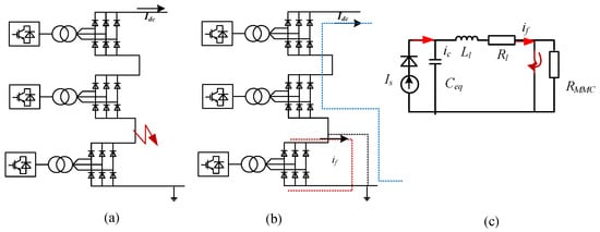
Figure 5.
Equivalent circuit of DC grounding fault, (a) topology, (b) fault current path, (c) equivalent circuit.
With the current limiter of the current controller in Figure 4, current will be limited without destroying the converters. The fault current if is:
where
As the unidirectional conduction of DR, other SCUs in the series-connected strings will not inject fault current and will continue working. Considering the advantage of a diode with high voltage and high current rating, if the fault current is more minor than 1.5 pu, the SCUs will not be blocked during a DC fault, and fast recovery of the whole system will be expected. Once the fault current exceeds 1.5 pu, the S2 will open to protect the SCUs.
4.3. Open DC Line Fault
Once a permanent open DC line fault occurs, active power transmission of the series-connected branch will be stopped, and a long time may be needed for repair. To reduce the active power loss, extra switches and cables are used to reconfigure the series-connected SCUs. Three reconfiguration topologies are discussed here, as shown in Figure 6.
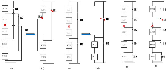
Figure 6.
Reconfiguration with switches when open DC line fault occurs, (a) reconfiguration topology one, (b) equivalent circuit of reconfiguration one after a fault occurs, (c) reconfiguration topology two, (d) equivalent circuit of reconfiguration two after a fault occurs, (e) reconfiguration topology three, (f) equivalent circuit of reconfiguration three after a fault occurs.
The cost of a wind farm based on SCUs includes cables and switches. The investment cost of the DC cable is proportional to the two factors of cable length Li and cable capacity Si [30]:
where K is 1.4 k/USD/MW/km.
The comparison of the three configurations is shown in Table 1. It can be seen that topology three will offer the smallest power loss during the fault, but its investment is highest with more switches and higher rating switches. Although topology one shows the most minor investment, the series-connected topology will be parallel-connected, and overvoltage or overcurrent of the SCU will occur. The active power of the SCU will be limited to prevent the SCU from being damaged by overvoltage or overcurrent. Therefore, three Prate will be lost, although only two SCUs stop working. According to the economy and power loss during a fault, topology two would be a better choice.

Table 1.
Comparison of reconfiguration topologies.
5. Simulation
Taking the existing wind farm size and DC voltage levels into consideration, a DC collection system rated 160 MW is simulated in PSCAD/EMTDC with its dynamic performance. The rated current and voltage of the DC link are 0.5 kA and 320 kV, respectively. The series wind farm consists of 8 of 20 MW SCUs, which are combined by 2 of 10 MW SCUs. The DC wind farm produces a maximum power of 160 MW. An average model based on FB-MMC in [27] is used in the simulation, and the HVDC transmission cable is modeled as an equivalent resistance. The parameters are listed in Table 2.
Table 2.
Parameters of the system.
5.1. Start-Up
As the power flow of SCUs based on DR is unidirectional, assume that a small battery exists at the wind turbine and coordinate with the pitch control to supply power during startup.
The startup of the whole system is shown in Figure 7. At t = 0 s, s1 of the SCU is opened, and s2 is closed. The onshore MMC converter builds DC current through DR and reaches 0.5 kA at t = 0.57 s, as shown in Figure 7d and DC voltage of the HVDC link is 0, as shown in Figure 7c.
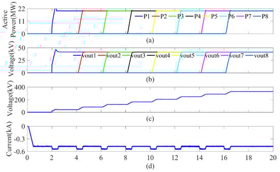
Figure 7.
Startup of the offshore wind farm, (a) Active power of SCU, (b) Output voltage of SCU, (c) DC voltage of HVDC link, (d) DC current of HVDC link.
At t = 2 s, SCU1 starts to generate a power of 20 MW, as shown in Figure 7a. With the increase of power, the output voltage of DR increases and reaches its rating voltage of 40 kV, as shown in Figure 7b, as well as the DC voltage of the HVDC link. At t = 4 s, SCU2 is open and starts to generate power of 20 MW, and the DC voltage of the HVDC increases to 80 kV. Each SCU is started one by one at t = 6 s, 8 s,10 s, 12 s, 14 s, and 16 s, as shown in Figure 7.
The DC current is controlled at 0.5 kA during startup. When the SCU is connected, a slight fluctuation occurs due to the existence of the current control loop. The arm bridge voltage and capacitor voltage of MMC is shown in Figure 8. It can be seen that the arm bridge voltage increases with the active power while capacitor voltage is controlled at approximately 2.5 kV. The whole system starts up smoothly.

Figure 8.
Waveforms of MMC during start-up, (a) Arm voltage of upper arm, (b) Average capacitor voltage of sub-model.
5.2. Wind Speed Growth Scenario
The performance of a series of DC wind farms with proposed control under unequal wind speed is simulated. The output power of each SCU is set to 20 MW initially. At t = 6 s, the power of SCU2 decreases to 16 MW, at t = 8 s, the power of SCU3 drops to 12 MW, and other SCUs decrease to 10MW at t = 10 s, 12 s, 14 s, 16 s, and 18 s, as shown in Figure 9a. The output voltage of SCU2 decreases to 33 kV and output voltage of SCU3 drops to 50 kV, and others decrease to 21 kV, as shown in Figure 9b. Under the power loop controller, the DC voltage of SCUs will be changed mediately and the DC voltage of SCUs is proportional to output power. The DC voltage of the HVDC link decreases with the power, as shown in Figure 9c. The DC current is controlled at 0.5 kA during active power fluctuation. Under the coordinate control strategy in Figure 4, every SCU can transmit its maximum power without being influenced by others.
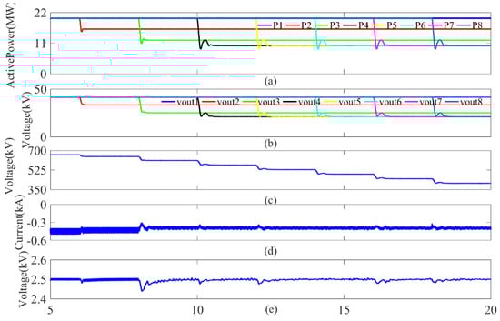
Figure 9.
Output power of DC wind farm during unequal wind speed (a) Active power of SCU, (b) Output voltage of SCU, (c) DC voltage of HVDC link, (d) DC current of HVDC link, (e) Capacitor voltage of sub-model.
5.3. AC Fault of Receiving End
A three-phase AC grounding fault occurs at t = 4 s, as shown in Figure 10. Three curves are used to compare the performance of the proposed protection strategy. ST1 represents a protection strategy in Equations (12) and (13) being used. ST2 represents no strategy being used.
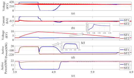
Figure 10.
Output power of DC wind farm during onshore fault (a) DC voltage of HVDC link, (b) DC current of HVDC link (c) Capacitor voltage of sub-model of MMC, (d) Output power of MMC, (e) Active power of SCU.
As shown in Figure 10, as the onshore converter operates as a DC current source and SCUs operate as a DC voltage source, the whole system shows different characteristics once an onshore fault occurs. It can be seen that the DC voltage of the HVDC link is approximately unchanged when an onshore AC grounding fault occurs, as shown in Figure 10a, while capacitor voltage keeps increasing, nearly reaching four times its nominal voltage without a strategy being used, as shown in Figure 10c, which is harmful to the MMC and results in the block of the MMC. It is not conducive to the recovery of the system after a fault.
With the ST1 being used, it can be seen that the DC current is controlled to 0, as shown in Figure 10b, and the DC voltage of the HVDC link increases to the maximum value and remains nearly unchanged during an onshore fault as shown in Figure 10a, while the capacitor voltage only reaches 1.24 times its nominal voltage, as shown in Figure 10c. With the increase of DC voltage of the HVDC link, the Vo will increase with Vout until it reaches the upper limiter of the power controller shown in Figure 4, making the SCU blocked, and active power cannot transmit to the HVDC link anymore according to Equation (5), as shown in Figure 10e. However, the DC voltage of the HVDC link reaches 1.3 times its nominal voltage because of the controller’s response time.
The fault last 0.5 s. Once the AC fault is cleared, the capacitor voltage controller in Figure 3 can work again with the end of saturation of current controller. The capacitor voltage is larger than its rating value during the AC fault and it will discharge first. The capacitor volage will drop first as shown in Figure 10c and a sudden pulse of active power can be observed in Figure 10d at t = 4.514 s. At t = 4.56 s, the capacitor voltage drops to the 2.2 kV and the pulse active power reaches its largest value 130 MW. During the discharging, the DC voltage of HVDC link is 0 kV, as shown in Figure 10a. Under the capacitor voltage controller, the pulse active power begins to decrease, and active power is extracted from AC grid to charge the capacitor. Capacitor voltage increase to 2.6 kV until t = 5.08 s and the DC voltage of HVDC link increase to its nominal value. The active power transmission recovers at this time as shown in Figure 10d,e. However, the capacitor voltage is still large than its reference value and it takes more time for the controller to recover until t = 6.56 s. It takes about 2 s for the whole system to recover from fault.
5.4. DC Grounding Fault U
A pole-to-ground DC fault occurs at the point between SCU6 and SCU7 at t = 8 s. The voltage of the SCU drops to 0 immediately, as the red line shown in Figure 11a. The output DC current of the SCUs is shown in Figure 11b. With the discharging of the filter at the lower side of a wind turbine, the maximum DC current is 1.6 times that of rating current. As the filter is located at AC side of DR, as shown in Figure 1, the fault current will flow by DR and may destroy the diodes. So, the selection of diode should be carefully. Then, the fault current decreases and flows through the diode for freewheeling. Finally, the DC current flowing through SCU7 keeps at 1.2 times that of the rating current with the current limiter of SCUs until SCU7 and SCU8 are removed.

Figure 11.
Waveforms of DC wind farm during DC fault (a) DC voltage of HVDC link and SCU, (b) DC current of HVDC link and SCU (c) current of SCU, (d) Output power of MMC, (e) Active power of SCU.
After the DC fault occurs, because of the coupling characteristics of DR, the AC voltage of MF drops with DC voltage, and the AC current of MF, which is affected by the current limit control, is 1.2 pu, as the red line shown in Figure 11d. During fault, the active power drops to 0, as the red lines shown in Figure 11e.
According to Figure 11b,c, although the output current of healthy SCUs does not exceed its nominal value, these SCUs still contribute fault current and shows a current decrease at the moment fault occurs.
6. Conclusions
This paper proposes a series-connected DC wind farm based on DR and solves the coupling issues, including energy curtailment and fault isolation.
- (1)
- With the coupling mechanism analysis, it is pointed out that the CDC mode is suitable for SCUs to eliminate energy curtailment without an auxiliary control strategy or equipment during unequal wind speed. Characteristics of DR are analyzed, and the linear relationship among active power, AC voltage of the MF transformer, output DC voltage, and output DC current of SCUs is researched first. Combining DR characteristics and CDC mode, a coordinate control strategy for the DC wind farm is proposed, where the receiving end converter operates as a DC current source with the DC current controller and the offshore wind turbine operates as a DC voltage source with a triple loop mediate AC voltage control strategy. Under the coordinate control strategy, the SCUs can track its MPPT without energy curtailment or overvoltage issues.
- (2)
- The fault isolation problems caused by SCUs are analyzed. Benefiting from the unidirectional conduction characteristics of DR, the healthy SCUs can keep operating without special equipment after a grounding DC fault occurs and the AC current of fault ones is smaller than 1.2 pu without destruction of SCUs. Considering the power loss and economy, reconfiguration switches are proposed, and only 40% active power is lost before the broken DC line is repaired. In addition, the characteristics of an AC fault located at the onshore grid are analyzed. A detecting and protection strategy is proposed for onshore AC fault without communication to protect the MMC from destruction quickly with sub-module voltage smaller than 1.12 pu.
With the topology of SCUs based on DR, the offshore platform is removed and investment for offshore wind farms is cut further. Under the proposed control strategy, the energy curtailment is eliminated, and fault isolation is achieved with the unidirectional conduction of DR with less equipment. The simulation results validate the effectiveness of the control strategy, and the performance of whole system is well during startup, power fluctuation, onshore fault, and DC fault. As this paper focus on just the medium-voltage DC collection system, the power of whole system is still small, the improved topology for large offshore wind power transmission will be studied in the future.
Author Contributions
Conceptualization, methodology, validation, and formal analysis, L.X.; writing—original draft preparation, L.X.; writing—review and editing, F.C. and J.W. All authors have read and agreed to the published version of the manuscript.
Funding
This research was funded by National Key R&D Program of China, grant number is 2021YFB2401100.
Institutional Review Board Statement
Not applicable.
Informed Consent Statement
Not applicable.
Data Availability Statement
The authors declare no conflict of interest.
Acknowledgments
This paper is well supervised by Liangzhong Yao and Yue hui Huang. We wish to thank the timely help given by them in analyzing fault characteristics. Funding from the State Key Laboratory of Advanced Power Transmission Technology is gratefully acknowledged.
Conflicts of Interest
The authors declare no conflict of interest. The funders had no role in the design of the study; in the collection, analyses, or interpretation of data; in the writing of the manuscript, or in the decision to publish the results.
References
- Zhao, C.; Jiang, S.; Xie, Y.; Wang, L.; Zhang, D.; Ma, Y.; Zhang, Y.; Li, M. Analysis of Fault and Protection Strategy of a Converter Station in MMC-HVDC System. Sustainability 2022, 14, 5446. [Google Scholar] [CrossRef]
- Apostolaki-Iosifidou, E.; Mccormack, R.; Kempton, W.; Mccoy, P.; Ozkan, D. Transmission Design and Analysis for Large-Scale Offshore Wind Energy Development. IEEE Power Energy Technol. Syst. J. 2019, 6, 22–31. [Google Scholar] [CrossRef]
- Hossain, M.I.; Abido, M.A. SCIG Based Wind Energy Integrated Multiterminal MMC-HVDC Transmission Network. Sustainability 2020, 12, 3622. [Google Scholar] [CrossRef]
- Miyara, R.; Nakadomari, A.; Matayoshi, H.; Takahashi, H.; Hemeida, A.M.; Senjyu, T. A Resonant Hybrid DC Circuit Breaker for Multi-Terminal HVDC Systems. Sustainability 2020, 12, 7771. [Google Scholar] [CrossRef]
- Tian, S.; Campos-Gaona, D.; Lacerda, V.A.; Torres-Olguin, R.E.; Anaya-Lara, O. Novel Control Approach for a Hybrid Grid-Forming HVDC Offshore Transmission System. Energies 2020, 13, 1681. [Google Scholar] [CrossRef] [Green Version]
- Blasco-Gimenez, R.; Ano-Villalba, S.; Rodríguez-D’Derlée, J.; Morant, F.; Bernal-Perez, S. Distributed voltage and frequency control of offshore wind farms connected with a diode-based HVDC link. IEEE Trans. Power Electron. 2010, 25, 3095–3105. [Google Scholar] [CrossRef]
- Bernal-Perez, S.; Ano-Villalba, S.; Blasco-Gimenez, R.; Rodriguez-D’Derlee, J. Efficiency and fault ride-through performance of a diode-rectifier-and VSC-inverter-based HVDC link for offshore wind farms. IEEE Trans. Ind. Electron. 2012, 60, 2401–2409. [Google Scholar] [CrossRef]
- Prignitz, C.; Eckel, H.G.; Knaak, H.J. Voltage and current behavior in a FixReF controlled offshore wind farm using a HVDC transmission system based on uncontrolled diode rectifier units. In Proceedings of the 2016 18th European Conference on Power Electronics and Applications, Karlsruhe, Germany, 5–9 September 2016. [Google Scholar]
- Prignitz, C.; Eckel, H.G.; Achenbach, S.; Augsburger, F.; Schön, A. FixReF: A control strategy for offshore wind farms with different wind turbine types and diode rectifier HVDC transmission. In Proceedings of the 2016 IEEE 7th International Symposium on Power Electronics for Distributed Generation Systems (PEDG), Vancouver, BC, Canada, 27–30 June 2016. [Google Scholar]
- Herrera, D.; Galván, E.; Carrasco, J.M. Method for controlling voltage and frequency of the local offshore grid responsible for connecting large offshore commercial wind turbines with the rectifier diode-based HVDC-link applied to an external controller. IET Electr. Power Appl. 2017, 11, 1509–1516. [Google Scholar] [CrossRef]
- Yu, L.; Li, R.; Xu, L. Distributed PLL-based control of offshore wind turbines connected with diode-rectifier-based HVDC systems. IEEE Trans. Power Deliv. 2018, 33, 1328–1336. [Google Scholar] [CrossRef] [Green Version]
- Li, R.; Yu, L.; Xu, L. Offshore AC fault protection of diode rectifier unit-based HVDC system for wind energy transmission. IEEE Trans. Ind. Electron. 2018, 66, 5289–5299. [Google Scholar] [CrossRef] [Green Version]
- Lian, Y.; Finney, S.J. DC collection networks for offshore generation. In Proceedings of the 2nd IET Renewable Power Generation Conference (RPG 2013), Beijing, China, 9–11 September 2013; pp. 1–4. [Google Scholar]
- Liu, H.; Dahidah, M.S.; Yu, J.; Naayagi, R.T.; Armstrong, M. Design and Control of Unidirectional DC–DC Modular Multilevel Converter for Offshore DC Collection Point: Theoretical Analysis and Experimental Validation. IEEE Trans. Power Electron. 2019, 34, 5191–5208. [Google Scholar] [CrossRef]
- Zhang, H.; Gruson, F.; Rodriguez, D.M.; Saudemont, C. Overvoltage Limitation Method of an Offshore Wind Farm with DC Series-Parallel Collection Grid. IEEE Trans. Sustain. Energy 2019, 10, 204–213. [Google Scholar] [CrossRef] [Green Version]
- Rong, F.; Wu, G.; Li, X.; Huang, S.; Zhou, B. ALL-DC Offshore Wind Farm with Series-Connected Wind Turbines to Overcome Unequal Wind Speeds. IEEE Trans. Power Electron. 2019, 34, 1370–1381. [Google Scholar] [CrossRef]
- Popat, M.; Wu, B.; Liu, F.; Zargari, N. Coordinated Control of Cascaded Current-Source Converter Based Offshore Wind Farm. IEEE Trans. Sustain. Energy 2012, 3, 557–565. [Google Scholar] [CrossRef]
- Guo, G.; Song, Q.; Zhao, B.; Rao, H.; Xu, S.; Zhu, Z.; Liu, W. Series-Connected-Based Offshore Wind Farms with Full-Bridge Modular Multilevel Converter as Grid- and Generator-side Converters. IEEE Trans. Ind. Electron. 2020, 67, 2798–2809. [Google Scholar] [CrossRef]
- Chuangpishit, S.; Tabesh, A.; Moradi-Shahrbabak, Z.; Saeedifard, M. Topology Design for Collector Systems of Offshore Wind Farms with Pure DC Power Systems. IEEE Trans. Ind. Electron. 2014, 61, 320–328. [Google Scholar] [CrossRef]
- Guo, G.; Zha, K.; Zhang, J.; Wang, Z.; Zhang, F.; Cao, J. Grounding Fault in Series-Connection-Based Offshore Wind Farms: Fault Clearance. IEEE Trans. Power Electron. 2020, 35, 9357–9367. [Google Scholar] [CrossRef]
- Lakshmanan, P.; Guo, J.; Liang, J. Energy curtailment of DC series–parallel connected offshore wind farms. IET Renew. Power Gener. 2018, 12, 576–584. [Google Scholar] [CrossRef]
- Xiong, Y.; Yao, W.; Wen, J.; Lin, S.; Ai, X.; Fang, J.; Wen, J.; Cheng, S. Two-Level Combined Control Scheme of VSC-MTDC Integrated Offshore Wind Farms for Onshore System Frequency Support. IEEE Trans. Power Syst. 2020, 29, 781–792. [Google Scholar] [CrossRef]
- Li, Y.; Gao, W.; Huang, S.; Wang, R.; Yan, W.; Gevorgian, V.; Gao, D.W. Data-Driven Optimal Control Strategy for Virtual Synchronous Generator via Deep Reinforcement Learning Approach. J. Mod. Power Syst. Clean Energy 2021, 9, 919–929. [Google Scholar] [CrossRef]
- Holtsmark, N.; Bahirat, H.J.; Molinas, M.; Mork, B.A.; Hoidalen, H.K. An All-DC Offshore Wind Farm with Series-Connected Turbines: An Alternative to the Classical Parallel AC Model. IEEE Trans. Ind. Electron. 2013, 60, 2420–2428. [Google Scholar] [CrossRef]
- Adam, G.P.; Williams, B.W. Half and Full-Bridge Modular Multilevel Converter Models for Simulations of Full-Scale HVDC Links and Multi-terminal DC grids. IEEE J. Emerg. Sel. Top. Power Electron. 2014, 2, 1089–1108. [Google Scholar] [CrossRef] [Green Version]
- Chen, C.; Adam, G.P.; Finney, S.; Fletcher, J.; Williams, B. H-bridge modular multi-level converter: Control strategy for improved DC fault ride-through capability without converter blocking. IET Power Electron. 2015, 8, 1996–2008. [Google Scholar] [CrossRef]
- Adam, G.P.; Davidson, I.E. Robust and Generic Control of Full-Bridge Modular Multilevel Converter High-Voltage DC Transmission Systems. IEEE Trans. Power Deliv. 2015, 30, 2468–2476. [Google Scholar] [CrossRef] [Green Version]
- Cheng, F.; Yao, L.; Xu, J.; Chi, Y.; Sun, Y.; Wang, Z.; Yan, L.A. A comprehensive AC fault ride-through strategy for HVDC link with serial-connected LCC-VSC hybrid inverter. CSEE J. Power Energy Syst. 2022, 8, 175–187. [Google Scholar]
- Xie, L.; Yao, L.; Cheng, F.; Li, Y.; Shuai, L. Coordinate control strategy for stability operation of offshore wind farm integrated with Diode-rectifier HVDC. Global Energy Interconnect. 2020, 3, 205–216. [Google Scholar] [CrossRef]
- Taherbaneh, M.; Jovcic, D.; Taisne, J.P.; Nguefeu, S. DC Fault Performance and Cost Analysis of DC Grids. In Proceedings of the 2013 IEEE Grenoble Conference, Grenoble, France, 16–20 June 2013. [Google Scholar]
Publisher’s Note: MDPI stays neutral with regard to jurisdictional claims in published maps and institutional affiliations. |
© 2022 by the authors. Licensee MDPI, Basel, Switzerland. This article is an open access article distributed under the terms and conditions of the Creative Commons Attribution (CC BY) license (https://creativecommons.org/licenses/by/4.0/).