Article

Optimal Control of an Energy-Storage System in a Microgrid for Reducing Wind-Power Fluctuations

1
Department of Electrical Engineering, Ilam University, Ilam 69315-516, Iran
2
Department of Electrical Engineering, University of Bonab, Bonab 55517-61167, Iran
3
Faculty of Civil Engineering, Technische Universität Dresden, 01067 Dresden, Germany
*
Author to whom correspondence should be addressed.
Sustainability 2022, 14(10), 6183; https://doi.org/10.3390/su14106183
Submission received: 25 February 2022 / Revised: 10 May 2022 / Accepted: 16 May 2022 / Published: 19 May 2022
(This article belongs to the Special Issue Renewable Energy Technologies and Microgrids)

Abstract

:
In conventional low-voltage grids, energy-storage devices are mainly driven by final consumers to correct peak consumption or to protect against sources of short-term breaks. With the advent of microgrids and the development of energy-storage systems, the use of this equipment has steadily increased. Distributed generations (DGs), including wind-power plants as a renewable energy source, produces vacillator power due to the nature of variable wind. Microgrids have output power fluctuations, which can cause devastating effects such as frequency fluctuations. Storage can be used to fix this problem. In this paper, a grid-connected wind turbine and a photovoltaic system are investigated considering the atmospheric conditions and wind-speed variations, and a control method is proposed. The main purpose of this paper is to optimize the capacity of energy-storage devices to eliminate power fluctuations in the microgrid. Finally, the conclusion shows that, in microgrids with supercapacitors, the optimal capacity of microgrid supercapacitors is determined. This method of control, utilizing the combined energy-storage system of the battery supercapacitor, in addition to reducing the active power volatility of the wind turbine and photovoltaic generation systems, also considers the level of battery protection and reduction in reactive-power fluctuations. In the proposed control system, the DC link in the energy-storage systems is separate from most of the work conducted, which can increase the reliability of the whole system. The simulations of the studied system are performed in a MATLAB software environment.

1. Introduction

Initially, all electricity was supplied by fossil-fuel (FC) power plants, but as the population grew and pollution from fossil fuels increased, the use of alternative sources, such as renewable energy that includes fuel cells, photovoltaics (PVs), and wind energy, has significantly increased. An active grid, the processes of production and distribution, and energy consumption implemented in a controlled manner can form a microgrid. A microgrid is an independent distribution grid that has been formed from the community of distributed production units, controlled loads, and, usually, energy-storage systems (ESSs) [1,2,3,4,5,6,7].
In renewable-energy sources (RESs), such as wind turbines (WTs), since productive power directly depends on the atmospheric circumstances and wind blowing, the energy output of wind farms has one random nature. This issue challenges the power quality at common connectivity points, as well as voltage and frequency regulation and reliability. One effective solution to improve the reliability and performance of wind-energy systems is the integration of energy-storage equipment in a system grid [8,9,10,11,12,13]. In [14], different energy-storage technologies were compared in terms of returns and their prices at different time scales, and the key aspects of the use of energy storage were investigated by the probabilistic method. Among the storage equipment, the large battery, flywheels, supercapacitors, and superconductor magnetic-energy-storage systems as storage options of promised wind energy have been identified and their applications to the wind-energy system have been widely studied. In [15], a dynastic structure power-quality control for a combined wind/battery system suggested that, due to these levels of control and because battery-energy-storage systems on a large scale are relatively expensive, the battery charge status within a defined range is kept constant. In this reference, the level of a converter control voltage source includes an internal loop for current control, which complicates the control system. In [16], to reduce wind-power fluctuations, compressed air storage was used. These forms of storage need a lot of investment; however, they have slow-speed-adjustment dynamics and are not suitable for wind farms. To compensate for wind-turbine output power fluctuations, a superconducting magnetic energy-storage system was applied [17]. However, again, the price of this storage equipment restricts its use to reduce wind-turbine-power fluctuations. In [18], to reduce output power fluctuations in a wind farm, a battery storage-based control method was suggested. In this reference, in order to reduce the output power fluctuation, the energy-storage system was installed in the DC link for each wind turbine.
Compared to batteries, the advantages of supercapacitors as pulsed-power devices included higher power densities, higher efficiencies, longer lifetimes, and more charge and discharge times. The first disadvantage of supercapacitors in comparison to batteries is their relatively low energy density (watt-hour per kilogram or watt-hour per pound), which are used in applications with relatively high energy values before recharging the supercapacitor is required. Additionally, the high cost of supercapacitors is one of these disadvantages. Supercapacitors can be recharged in a very short time compared to batteries (seconds or a fraction of a second), of course, if an energy source is available to provide the power needed at a high level. Therefore, considering the advantages and disadvantages of each, the combination of battery storage and the supercapacitor can be a useful tool [19,20]. In [1], the combination of battery- and supercapacitor-storage systems has been used to reduce wind-turbine-power fluctuations and reduce frequency fluctuations based on the DROOP method. The purpose of this paper is to determine the optimal capacity of storage devices in order to reduce power fluctuations in the form of an optimization problem. Intelligent control methods can also be used for this purpose in the future [21,22].
In this paper, a control method is proposed in which, in addition to reducing the active power fluctuation of wind-turbine-power generation and photovoltaic systems, the level of battery protection and the reduction in reactive-power fluctuations in a network bus based on a battery–supercapacitor combination energy-storage system for the benefits of both storage systems are considered. In the proposed control system, the DC link in the energy-storage systems is separate from most of the work conducted, which can increase the reliability of the whole system. Ultimately, the supercapacitor’s energy-storage resource is optimized by the Imperialist Competitive Algorithm method in the presence of this control system and the final results are shown here.

2. The Studied Structure of the Grid

The block diagram of the studied overall grid is shown in Figure 1. The microgrid is operated in grid-connected mode and includes a wind-turbine system, photovoltaic system, fixed load, ESS, and supercapacitor to reduce grid-power fluctuations.

2.1. Wind-Turbine System

In a decade, wind turbines with high power and a high cost were properly con-structed and exploited. On the other hand, the global market for turbine-generator electric power is still increasing. In most cases, induction generators (usually with a squirrel-cage rotor) are used for electrical power generation in wind turbines, the issue of which is due to the high strength and cheap cost of this machine [23]. Inductive generators are mostly used in a grid-connected mode because they require system stimulation. The induction generators can be used in separate systems of the network, which have enough reactive power to stimulate their own system [24].
Wind-energy systems restrict the energy movement of the wind and convert it to electrical energy. Real power extracted by turbine rotor blades from wind energy is equal to the difference between turbine high-flow wind power with turbine low-flow wind power:
p = 1 2 k m ( v v 0 ) 2
In this equation, v is the wind speed of the turbine’s high flow at the inlet of the turbine blades and v is the wind speed of the low flow at the outlet of the turbine blades. Km is the mass-flow rate of the wind flow that is produced by the following equation. A is the cross-section swept by turbine blades.
K m = ρ A v + v 0 2
Finally, assuming C P = 1 2 ( 1 V V 0 ) [ 1 ( V V 0 ) 2 ] (Cp is the rotor-efficiency factor), the mechanical power extracted by the rotor is expressed in Equation (3). The schematic of a wind turbine is shown in Figure 2.
P = 1 2 ρ A v 3 C v

2.2. Battery-Energy-Storage System

Batteries are one of the elements that are advantageous to the economy that are available nowadays. Each battery consists of electrochemical cells that are connected in series–parallel combination. This series–parallel combination consists of a set of low-voltage/power batteries that have an optimal electrical characteristic. An energy-storage system modeled by one series-controlled voltage source with one fixed-resistance was based on [25]. The state of charge (SOC) is in fact the ratio of the amount of energy in the battery to its total capacity expressed as a percentage and determined according to Equation (4).
S O C = 100 ( S O C i n t   I b a t d t Q )
In the SOCint state of the battery’s initial state, Q is the capacity of the battery, which is modeled according to a controlled voltage source based on Equation (5).
E b a t = E 0 K 1 S O C S O C Q + A e B ( 1 S O C ) Q
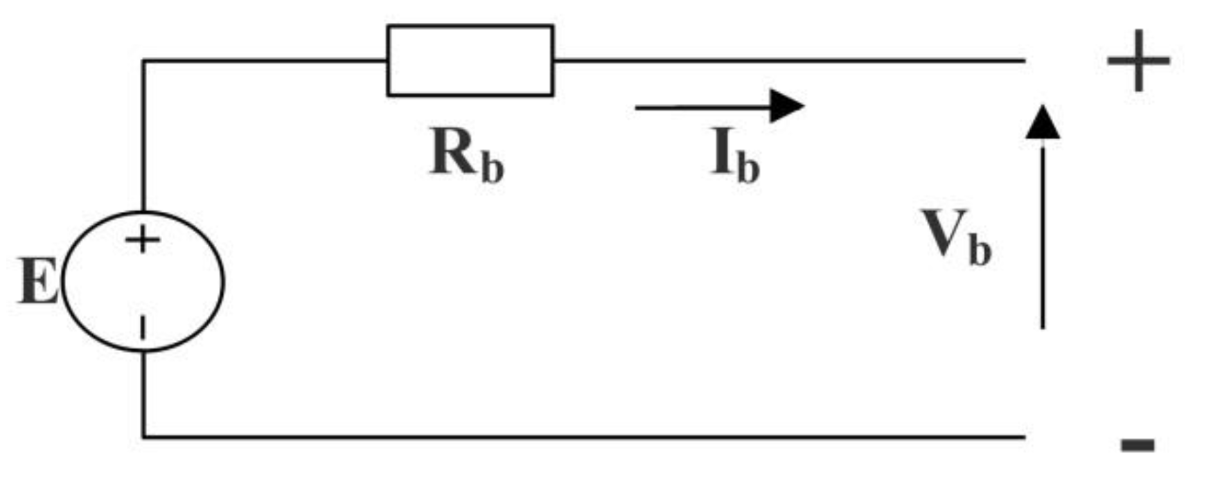
In this equation, Ebat is an open-circuit voltage, E0 is the rated voltage of the battery, K is the polarization voltage, Q is the capacity of the battery, A is the exponential voltage, and B is the exponential capacity [19]. Figure 3 represents the simple nonlinear model of battery.

2.3. Supercapacitor Energy-Storage System

The capacitor’s stored energy informs an electric field with an accumulation of positive and negative loads on two parallel plates. Different models for supercapacitors have been presented in various papers, which were very complex or simple, as needed.
In [26], the model that was the easiest to present for a supercapacitor includes a capacitor and a series resistance. This model is similar to the presentation model shown in Figure 4, with the difference that there is no parallel leakage resistance. In spite of its simplicity, this model is a good model of super capacity behavior in such a system, while reducing the complexity of the system to a great extent.
In the present study, the aim was not to study and model the supercapacitor, so a simple model was sufficient. In this paper, the model for a supercapacitor was considered.
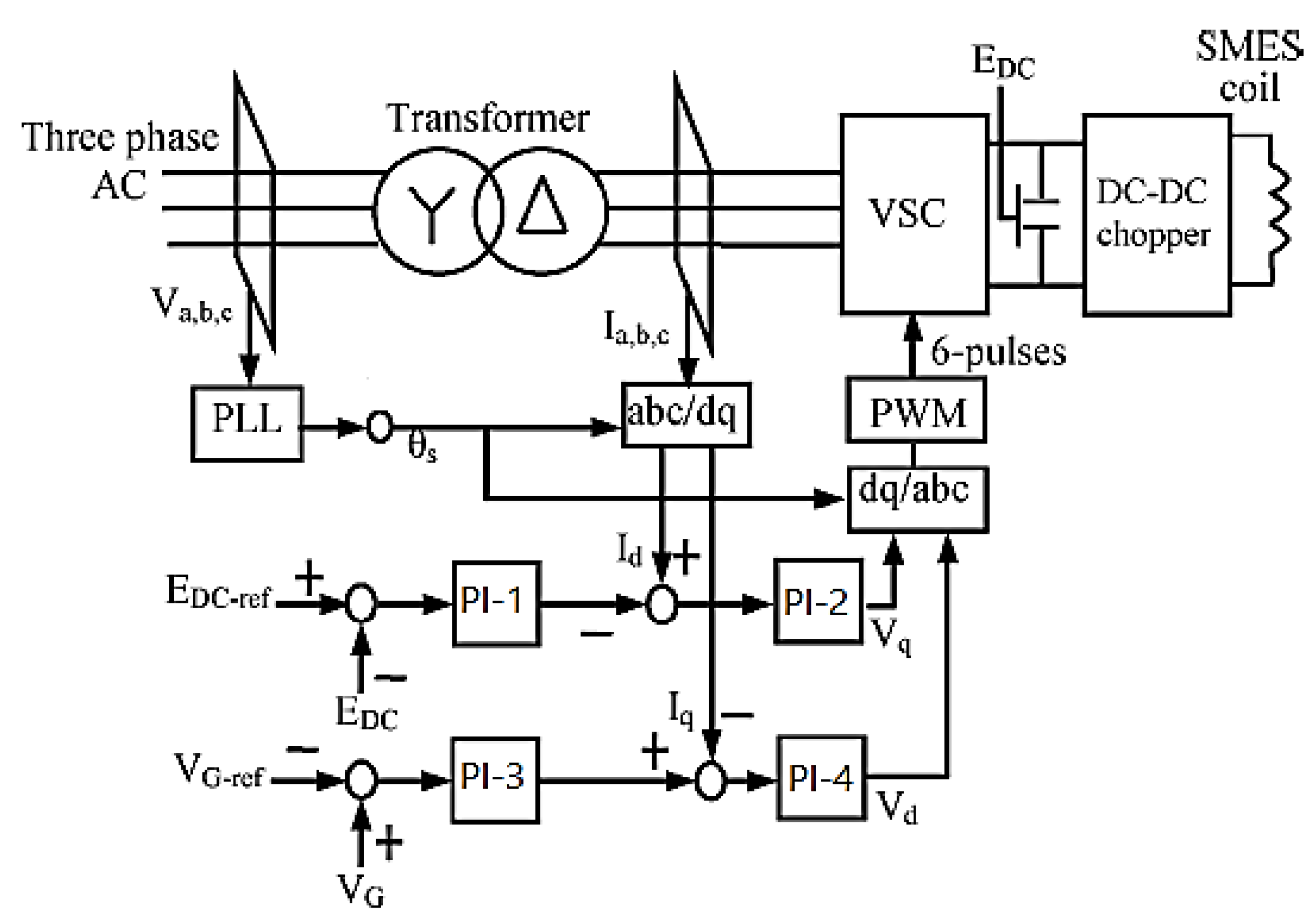
As shown in Figure 5, the superconducting control system includes a VSC connector with a pulse-width modulation, a DC-link capacitor, a chopper with two IGBT switches an LCL filter, and a triangle star transformer [20]. The VSC connector was connected between the AC power system and the supercapacitor. The voltage-source converter consisted of two IGBT bridges for low-rising harmonics. The voltage source and DC–DC copper converter were connected to each other with a DC-link capacitor [27,28]. The voltage-source converter provided an electronic power intermediary between the AC power system and the superconductor coil. The phase lock loop method was used to hold the converter’s switching at a predetermined fixed-frequency level [29,30]. The DC-link and network-point voltages were kept constant by the VSC.
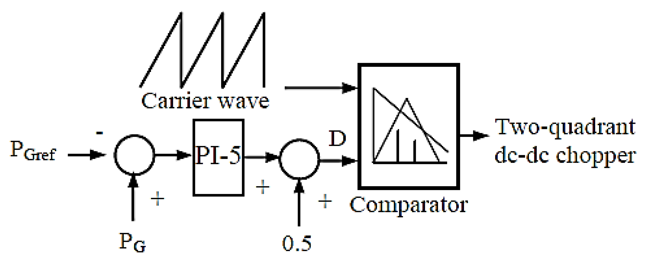
The power control of the supercapacitor was performed by the chopper. The reference power generated for the short-term supercapacitor was transferred to the supercapacitor power control and, as shown in Figure 6, generated the duty cyclic dictation needed to control the DC/DC chopper. Based on the amount of duty cycle D, there are three areas for the operation of the chopper. If the D cycle is larger or smaller than 0.5, the supercapacitor is charged or discharged, respectively. When the supercapacitor was in standby mode (D = 0.5), the supercapacitor voltage was constant and the current of the supercapacitor was zero. To generate choke-switch switching pulses based on Figure 7, the PWM reference signal was compared with a sawtooth wave. The coefficients of the PI controllers are presented in Table 1.

2.4. Battery and Supercapacitor Combined Energy-Storage Control Systems to Reduce Power Fluctuations

As noted, the energy generated by distributed turbine and solar cell systems fluctuates with the changing atmospheric conditions. These power fluctuations can cause undesired voltage, frequency, and grid-transient stability.
In this paper, a control method was introduced that used both the battery and supercapacitor storage systems and reduced the network power fluctuations, including wind turbines and photovoltaic systems. This control system benefits from both the battery and supercapacitor storage systems.
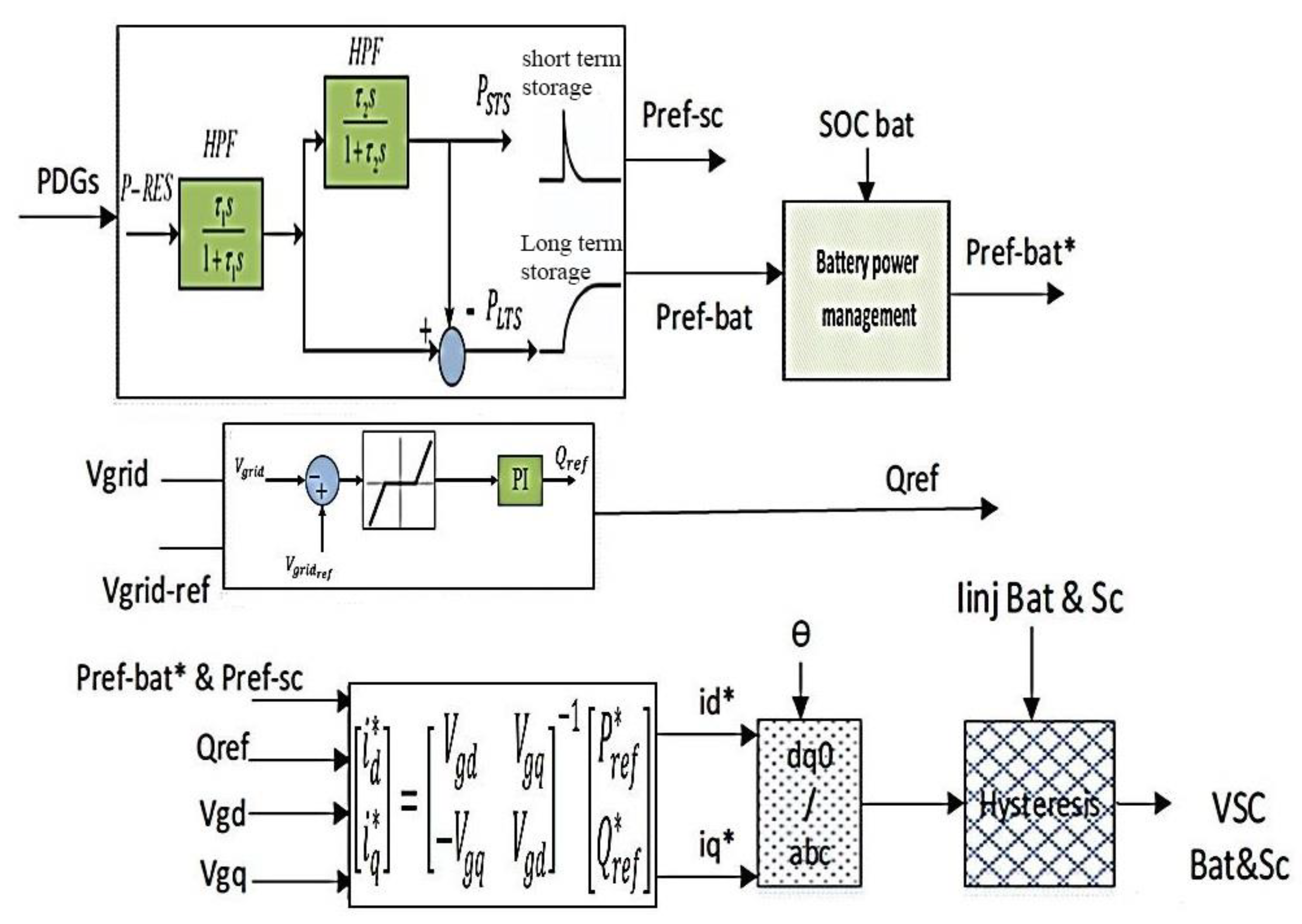
In order to smooth the injection power to the network, the instantaneous output power of the distributed generation sources as sampled and a first-order low-pass filter was used to filter high-frequency oscillating components. The difference between the power before and after filtering was used as a signal for charging or discharging the output of the battery and supercapacitor storage systems. With regard to the stated characteristics of each energy-storage system, reference powers were produced in proportion to each one, as shown in Figure 7.
This control strategy was based on three goals. The first goal was to reduce the output-power fluctuations of wind-turbine- and photovoltaic-distributed generation systems. The second goal was to keep the balance and the status of the battery charging and to prevent excessive charging and discharging. The third goal was to reduce network voltage changes, or to reduce the volatility of reactive power.
For this purpose, the control of the closed loop was based on the feedback from both the output power of the distributed generation sources, the battery-charging state, and the network voltage at the connection point. Battery-charging status is provided by the battery-management system. Signal P*ref, which is shown in Figure 8, ensured that the battery-charge mode stayed within the specified range. Otherwise, if the battery was below the permissible discharge limit (identified by the manufacturer) and reduced the active material inside it, as a result, the battery life was reduced. This range is usually equivalent to 30 capacity batteries considered. These limits are usually considered to be 30% of the battery capacity. It is desirable that the battery within the range of 30% to 70% of its capacity is charged and discharged. For this purpose, based on the level of protection that is considered in this article, when the difference between the state-of-charge reference and state-of-charge current, SOCbot, is placed inside the dead area, then P*ref = Pref; otherwise, to calculate the reference active power, we have: P*ref = Pref + Pbat.
The block diagram of this level of control is shown in Figure 9, and its relations are also based on formulas (6)–(8). For battery protection and to keep the SOC between 0.3 to 0.7, the SOC value should equal 50% and hold C1 = 0
Δ S O C = S O C r e f S O C b a t
{ e S O C = Δ S O C   | S O C | C 1 e S O C = 0   | S O C | < C 1
P S O C = e S O C G p l 1 = e S O C ( K P 1 + K l 1 s )
The other part of the network that demands a calculation is the reactive-power calculation, calculated by the block diagram (10) and relations (9)–(11). The reactive-power compensation unit receives a reference-, voltage input and a real-voltage input measured at the common connecting point; then the reference voltage decreases from the network voltage and the resulting signal is used to activate the function. A dead area and a PI controller were used to obtain Qref values for reactive-power control. When the voltage deviation ∆V is small (between the dead region), the block of the dead region produces zero output and Qref is zero.
Δ V = V g r i d V r e f
{ e V = Δ V   | Δ V | C 2 e V = 0   | Δ V | < C 2
Q r e f = e V ( K P 2 + K l 2 s )
In the control method, the power reference signal was used to generate switching reference signals for the battery and supercapacitor DC converters. The proposed control diagram is shown in Figure 10. However, this requires being sampled from the bus linear voltages of the grid. The sampled voltages of (VaVbVc) are converted by transforming the park into voltage signals of the three-phase voltage of the d and q axes. The modified and final power of the active and reactive references, coupled with the feedback from the network voltage and the transformation of the park, generates reference currents id and iq using Equation (12). These currents must be followed by BESS/VSC and SC/VSC output currents in order to compensate for the wind-turbine-power fluctuations by proper injection by the combined battery–supercapacitor energy storage system. Finally, in order to produce suitable switching pulses for the purpose mentioned, these currents, along with the SC/VSC and BESS/VSC output currents, are given to the hysteresis controller.
[ i * d i * q ] = [ V g d V g q V g q V g d ] 1 [ P * r e f Q * r e f ]
Generally, the capacity of the battery is determined by its energy capacity and its rated power. Energy capacity is the ability of the energy-storage system to store energy, and the nominal power determines the power that the energy-storage system can store or deliver to the network during charging or discharging.
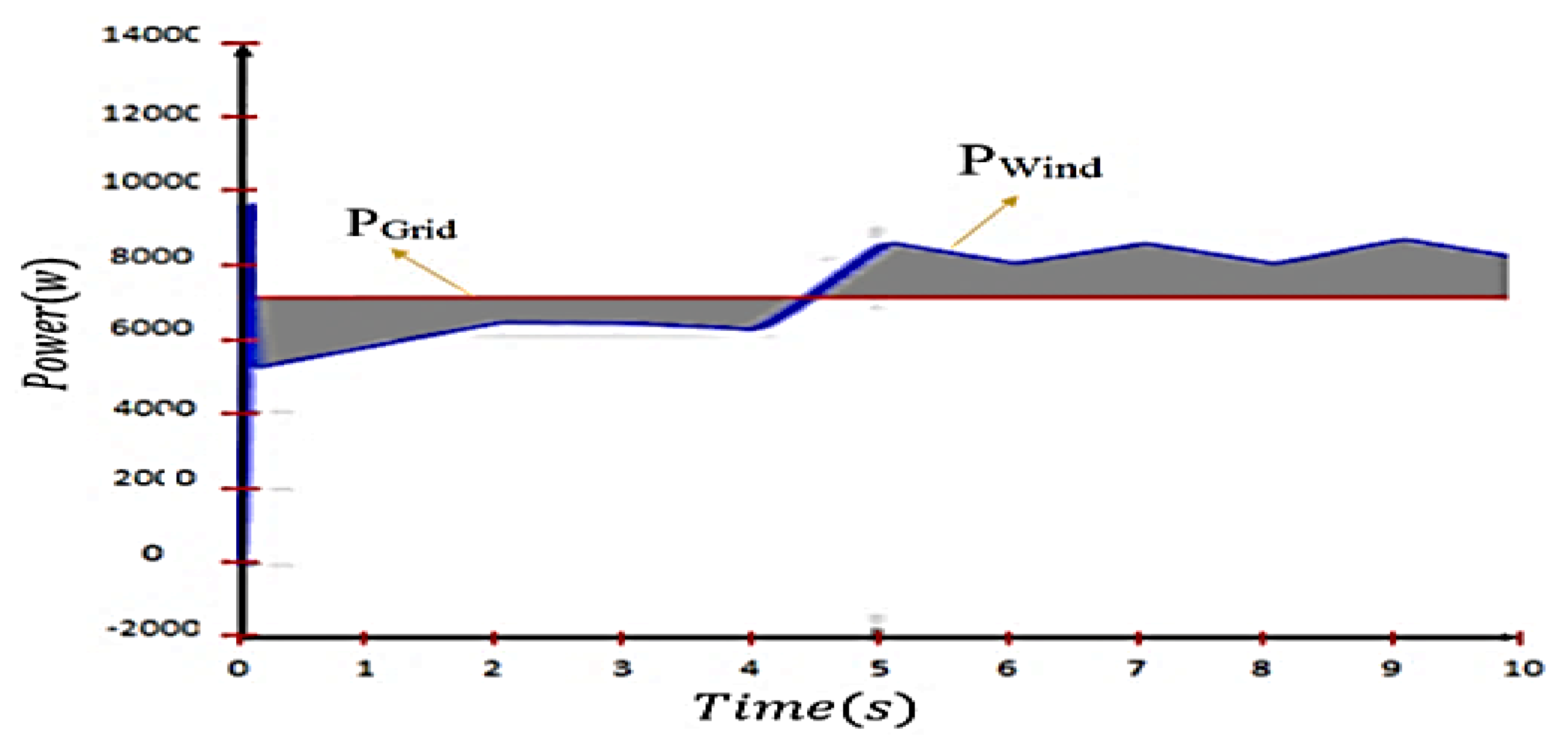
The wind pattern plays an important role in determining the size of the storage system, which means that, as the wind changes increase, storage capacity should also increase, which is itself an increase in economic costs. As shown in Figure 11, the grid power is constant. Before 4 s, the grid power is greater than the wind power, during which the storage must enter the circuit, and, after 4 s, the storage must absorb the power. According to Figure 11, the storage capacity required to exchange the network at any moment is equal to:
P E n e r g y   S t o r a g e = P W i n d P inf B u s

3. Optimal Supercapacitor Size

After performing simulations in the MATLAB software environment, first, by placing a large amount of experience in other papers, the accuracy of the proposed control system’s performance is verified. Then, using the imperialist competitive algorithm, the optimal value for the supercapacitor is found in such a way that reduces both the wind-turbine-power fluctuations and the lowest possible or least cost, and, on the other hand, a set of sustainability conditions are also included. Finally, using the optimized value, RUN is simulated once again and the results are verified.
The Imperialist Competitive Algorithm (ICA) is a method in the field of evolutionary computing that addresses the optimal answer to various optimization issues. This algorithm provides an algorithm for solving mathematical optimization problems by the mathematical modeling of the socio-political evolution process. The Imperialist Competitive algorithm is the initial set of possible solutions. These initial responses (countries) are gradually improved and ultimately provide the optimal answer (optimal country). The main pillars of this algorithm consist of national solidarity, royal competition, and revolution (revolution). This algorithm provides an algorithmic algorithm with the help of the process of developing social, economic, and political states, and mathematical modeling, which can help solve complex optimization problems. In fact, this algorithm examines country-level optimization responses and tries to improve these responses during the recurring process, and ultimately reach the optimal solution to the problem. In the article, the PI-5 controller conversion function in the supercapacitor con-troller is as follows: it controls the power of memory and injection functions and it is also the main controller of the supercapacitor.
K P ( s ) = K P P ( 1 + 1 τ i P )
In this equation, K P P and τ i P are the coefficient and the integrator of the controller.
In order to find the objective function of the imperialist algorithm, the goal is to optimize the amount of supercapacitor capacity, so that the power fluctuations are compensated in the desired amount. Therefore, we also considered a value for the amount of active power fluctuations as the percentage of power fluctuations defined as follows:
Δ P = P D G s P r e f P r e f × 100
This factor expresses the amount of fluctuation compensation in terms of percentages and limits it between a positive and negative 10%. In this relation, P r e f is derived from the abovementioned relation. By executing this algorithm, the optimal supercapacitor values are obtained. Therefore, the target functions are defined as follows:
{ F = 1 2 C S C V 2 S C 0   K m i n < K P P < K m a x T m i n < T i p < T m a x   1 < C m < 4 F
In which F is stored energy, K is control coefficients, and T is time constants.
After performing the simulations in the MATLAB/SIMULINK software environment, the PI-5 controller coefficients associated with the supercapacitor energy storage as well as the optimal supercapacitor value are obtained. For the algorithm outlined in this study, the number of countries is 1000, the number of empires is 100, and the number of replicates is 1000.
Finally, after simulating the control system and then simulating the optimization of the supercapacitor, the optimal PI-5 controller coefficients were and, and the optimum value obtained for the supercapacitor was 1.72 F.

4. Simulation Results

The simulation of the proposed system, as shown in Figure 12, was conducted using MATLAB/Simulink software.
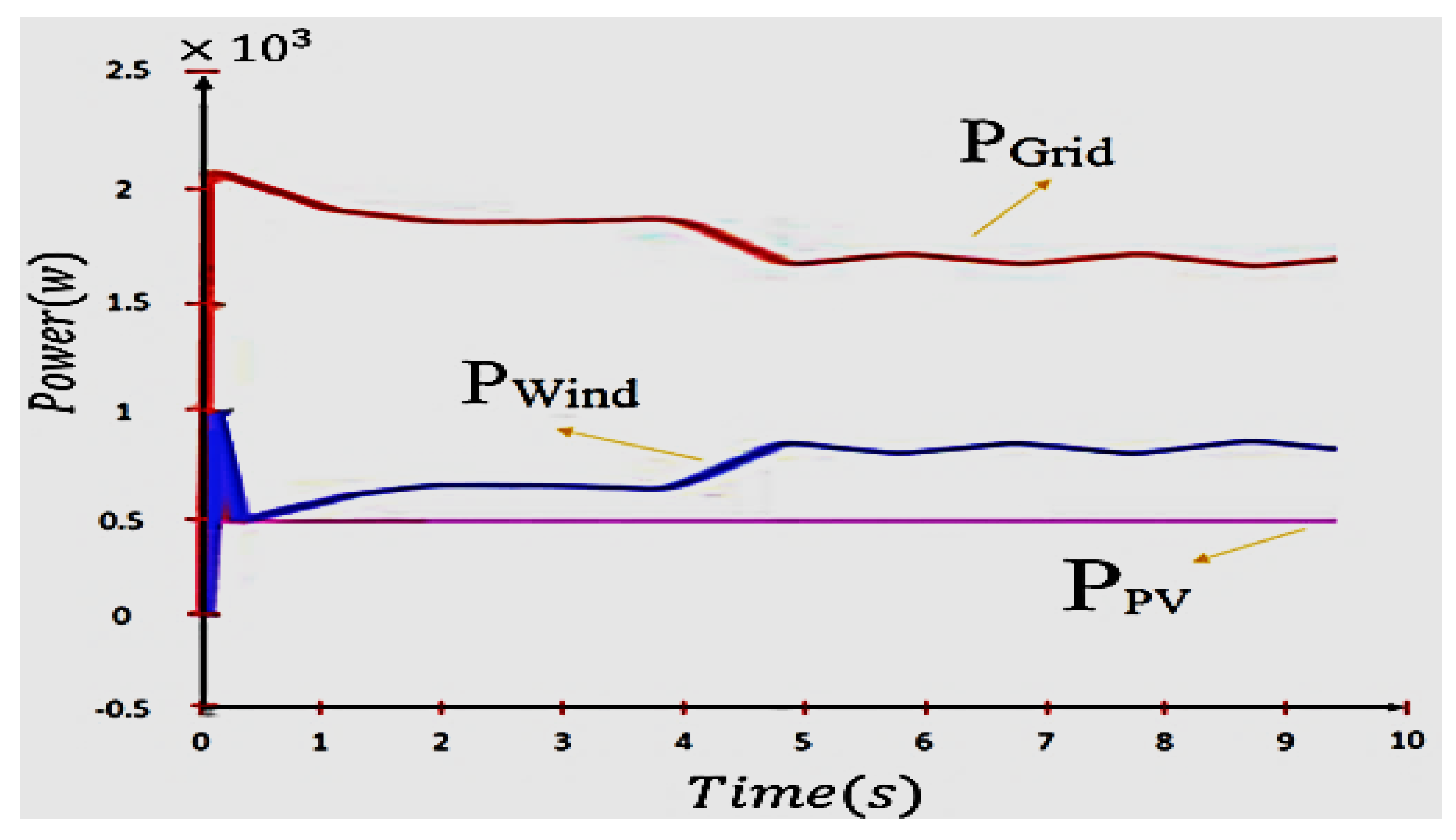
Due to variations in wind speed, the wind turbine output fluctuates. In this simulation, the production power of a photovoltaic system is assumed to be constant. As shown in Figure 13, the wind-turbine output power fluctuates with variations in the wind speed, based on the relationships expressed in Section 2.1, which indicate the dependence of wind-turbine output on wind speed.
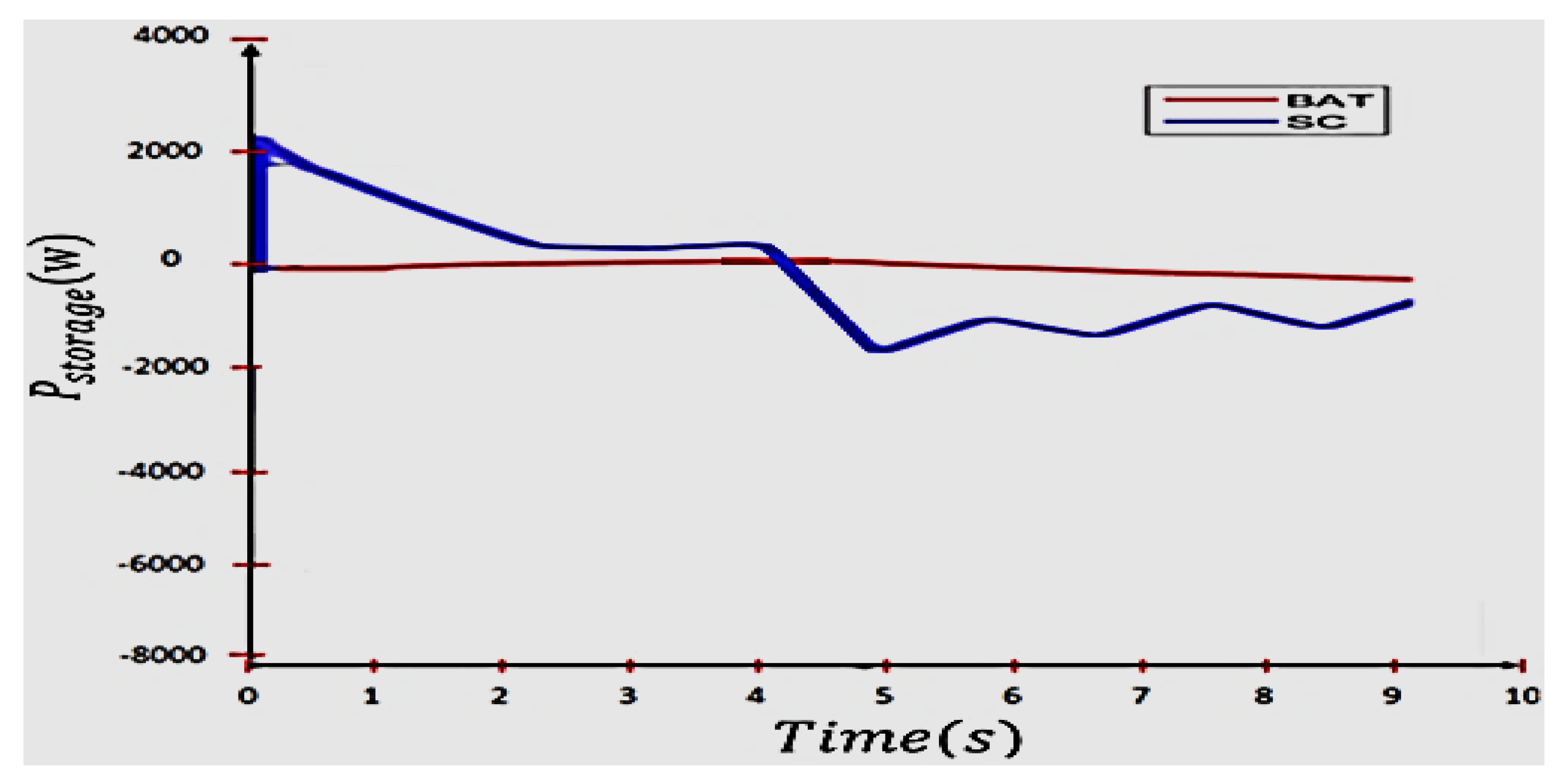
The power of the wind-turbine system, the photovoltaic system, and the power of the grid are shown in Figure 13, and the power production of the battery and supercapacitor energy-storage systems in Figure 14.
Additionally, the reference power of the control system, the calculation of the demand for battery power, the level of energy management of the battery, and the demand for super-capacities, along with the power of the energy-storage system of the battery and the supercapacitor, are displayed.
As shown in Figure 15 and Figure 16, to track reference powers for battery-storage systems and the supercapacitor, the verifier of the control system’s desirable performance is suggested.
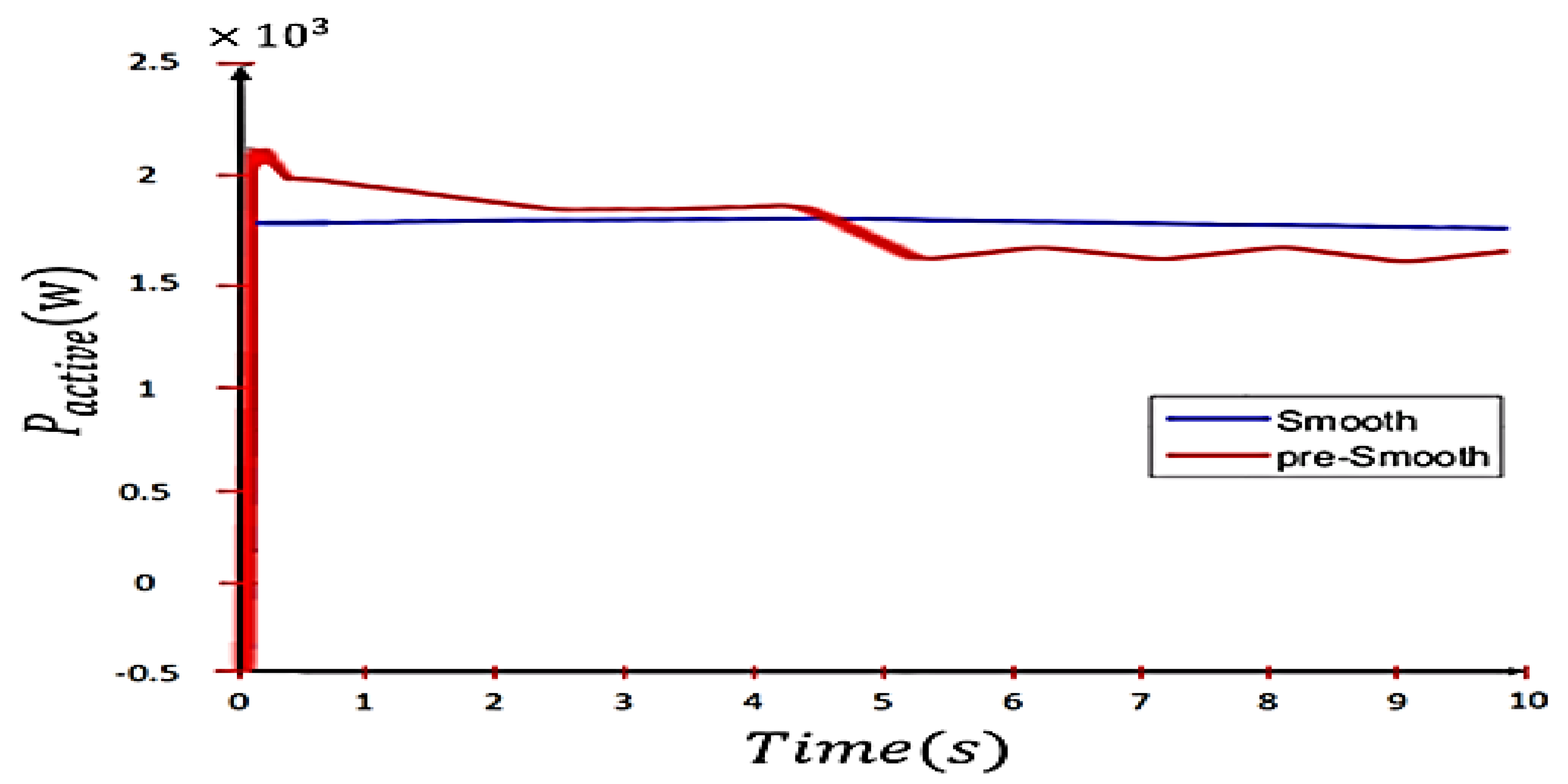
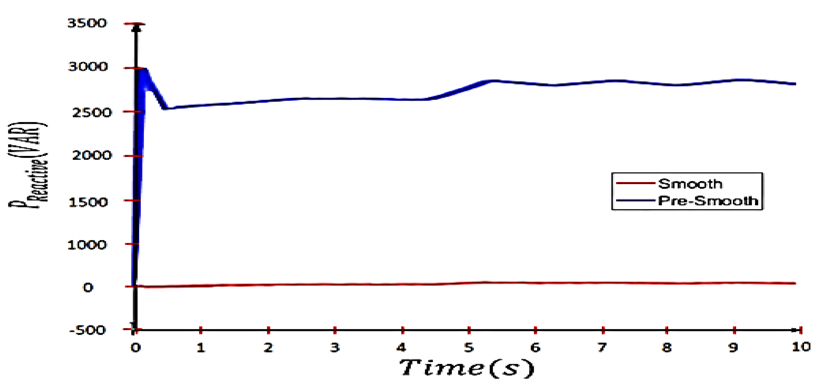
Finally, the active and reactive power of the network before and after the reduction in power fluctuations is shown in Figure 17. As we can observe in this figure, the proposed control system based on the combined energy-storage system of the battery and supercapacitor was able to dramatically reduce the power fluctuations from the viewpoint of the network.

5. Conclusions

In the microgrid, when we have power fluctuations, we also have frequency fluctuations that must be eliminated. Additionally, uncertainty of power in renewable sources can cause many problems. To deal with these problems, we need compensation methods to reduce power fluctuations and stabilize the system frequency. A storage device is used to control the amplitude of power fluctuations. Storage capacity is determined using an optimization problem that reduces power fluctuations using the proposed control operator. In this regard, using the electronic power element, such as energy storage, and also controlling it, is one of the best available methods. In this paper, by examining different control methods, a control method was proposed. By using this control method on the battery–superconducting combined energy-storage system, in addition to reactive-power compensation, the output power fluctuations of distributed generation systems can be reduced.
The simulation was conducted in the MATLAB/SIMULINK software environment and the results indicate the effectiveness of the proposed control strategy.
Additionally, the presence of distributed generation sources and energy storage, controllable loads, and power electronics created challenges in terms of power quality, reliability, and transient states that should be further explored in future work.

Author Contributions

Conceptualization, R.A., O.H., J.T., M.S., A.M. (Ardashir Mohammadzadeh) and A.M. (Amir Mosavi); Data curation, R.A., O.H., J.T., M.S. and A.M. (Amir Mosavi); Formal analysis, R.A., O.H., J.T. and M.S.; Funding acquisition, A.M. (Ardashir Mohammadzadeh) and A.M. (Amir Mosavi); Investigation, R.A. and J.T.; Methodology, R.A., O.H., J.T. and A.M. (Ardashir Mohammadzadeh); Project administration, R.A.; Resources, R.A., O.H., J.T., A.M. (Ardashir Mohammadzadeh) and A.M. (Amir Mosavi); Software, R.A. and O.H.; Supervision, R.A., O.H. and M.S.; Validation, R.A., J.T., M.S. and A.M. (Ardashir Mohammadzadeh); Visualization, R.A., J.T. and A.M. (Amir Mosavi); Writing—original draft, R.A. and M.S.; Writing—review and editing, R.A., M.S., A.M. (Ardashir Mohammadzadeh) and A.M. (Amir Mosavi). All authors have read and agreed to the published version of the manuscript.

Funding

This research received no external funding.

Institutional Review Board Statement

Not applicable.

Informed Consent Statement

Not applicable.

Data Availability Statement

Not applicable.

Conflicts of Interest

The authors declare no conflict of interest.

References

  1. Wright, S.; Frost, M.; Wong, A.; Parton, K.A. Australian Renewable-Energy Microgrids: A Humble Past, a Turbulent Present, a Propitious Future. Sustainability 2022, 14, 2585. [Google Scholar] [CrossRef]
  2. Ahmad, R.; Mohamed, A.A.A.; Rezk, H.; Dhaifallah, M.A. DC Energy Hubs for Integration of Community DERs, EVs, and Subway Systems. Sustainability 2022, 14, 1558. [Google Scholar] [CrossRef]
  3. Dris, Y.; Benhabib, M.C.; Meliani, S.M.; Dumbrava, V. Performance analysis of a hybrid farm (photovoltaic system wind turbine) connected to the grid using nine-switches converter. UPB Sci. Bull. Ser. C Electr. Eng. Comput. Sci. 2021, 83, 53–64. [Google Scholar]
  4. Mohammadi, F.; Mohammadi-ivatloo, B.; Gharehpetian, G.B.; Ali, M.H.; Wei, W.; Erdinç, O.; Shirkhani, M. Robust Control Strategies for Microgrids: A Review. IEEE Syst. J. 2021. [Google Scholar] [CrossRef]
  5. Jeon, J.H.; Kim, J.Y.; Kim, S.K.; Kim, J.M. Unified Compensation Control of a Hybrid Energy Storage System for Enhancing Power quality and Operation Efficiency in a Diesel and Wind-Turbine Based Stand-alone Grid. In Proceedings of the 3rd IEEE International Symposium on Power Electronics for Distributed Generation Systems (PEDG), Kiel, Germany, 25–28 June 2012; pp. 264–270. [Google Scholar]
  6. Hosseini, S.H.; Danyali, S.; Goharrizi, A.Y.; Sarhangzadeh, M. Three-phase four-wire grid-connected PV power supply with accurate MPPT for unbalanced nonlinear load compensation. In Proceedings of the 2009 IEEE International Symposium on Industrial Electronics, Seoul, Korea, 5–8 July 2009; pp. 1099–1104. [Google Scholar]
  7. Danyali, S.; Moradkhani, A.; Aazami, R.; Haghi, M. New Dual-Input Zero-Voltage Switching DC–DC Boost Converter for Low-Power Clean Energy Applications. IEEE Trans. Power Electron. 2021, 36, 11532–11542. [Google Scholar] [CrossRef]
  8. Iranmehr, H.; Aazami, R.; Tavoosi, J.; Shirkhani, M.; Azizi, A.; Mohammadzadeh, A.; Mosavi, A.H. Modeling the Price of Emergency Power Transmission Lines in The Reserve Market Due to The Influence of Renewable Resources. Front. Energy Res. 2022, 9. [Google Scholar] [CrossRef]
  9. Yang, D.; Zhang, C.; Jiang, C.; Liu, X.; Shen, Y. Interval Method Based Optimal Scheduling of Regional Multi-Microgrids with Uncertainties of Renewable Energy. IEEE Access 2021, 9, 53292–53305. [Google Scholar] [CrossRef]
  10. Zhang, Y.; Sun, H.; Guo, Y. Wind Power Prediction Based on PSO-SVR and Grey Combination Model. IEEE Access 2019, 7, 136254–136267. [Google Scholar] [CrossRef]
  11. Peng, X.; Liu, Z.; Jiang, D. A review of multiphase energy conversion in wind power generation. Renew. Sustain. Energy Rev. 2021, 147, 111172. [Google Scholar] [CrossRef]
  12. Barton, J.P.; David, G.I. Energy storage and its use with intermittent renewable energy. IEEE Trans. Energy Convers. 2004, 19, 441–448. [Google Scholar] [CrossRef]
  13. Danyali, S.; Niapour, S.A.K.H.M.; Hosseini, S.H.; Gharehpetian, G.B.; Sabahi, M. New Single-Stage Single-Phase Three-Input DC-AC Boost Converter for Stand-Alone Hybrid PV/FC/UC Systems. Electr. Power Syst. Res. 2015, 127, 1–12. [Google Scholar] [CrossRef]
  14. Wu, Y.; Su, P.; Wu, T.; Hong, J.; Hassan, M.Y. Probabilistic Wind-Power Forecasting Using Weather Ensemble Models. IEEE Trans. Ind. Appl. 2018, 54, 5609–5620. [Google Scholar] [CrossRef]
  15. Tavoosi, J.; Suratgar, A.A.; Menhaj, M.B.; Mosavi, A.; Mohammadzadeh, A.; Ranjbar, E. Modeling Renewable Energy Systems by a Self-Evolving Nonlinear Consequent Part Recurrent Type-2 Fuzzy System for Power Prediction. Sustainability 2021, 13, 3301. [Google Scholar] [CrossRef]
  16. He, J.; Pei, L.; Zheng, L. Dynamic modeling and design of a hybrid compressed air energy storage and wind turbine system for wind power fluctuation reduction. Comput. Chem. Eng. 2019, 122, 59–65. [Google Scholar]
  17. Kai, L.; Xu, H.; Ma, Q.; Zhao, J. Hierarchy Control of Power Quality for Wind-Battery Energy Storage System. IET Power Electron. 2014, 7, 2123–2132. [Google Scholar]
  18. Tan, J.; Li, G.J.; Tang, Z.W. Power control and benefit analysis based on compressed air energy storage in wind farms. Autom. Electr. Power Syst. 2011, 8, 33–37. [Google Scholar]
  19. Asao, T.; Takahashi, R.; Murata, T.; Tamura, J.; Kubo, M.; Kuwayama, A.; Matsumoto, T. Smoothing control of wind power generator output by superconducting magnetic energy storage system. In Proceedings of the 2007 International Conference on Electrical Machines and Systems (ICEMS), Seoul, Korea, 8–11 October 2007; pp. 302–307. [Google Scholar]
  20. Du, J.; Wei, X.; Li, J.; Wang, G.; Zang, C. Star Identification Based On Radial Triangle Mapping Matrix. IEEE Sens. J. 2022, 22, 8795–8807. [Google Scholar] [CrossRef]
  21. Huang, H.; Shirkhani, M.; Tavoosi, J.; Mahmoud, O. A New Intelligent Dynamic Control Method for a Class of Stochastic Nonlinear Systems. Mathematics 2022, 10, 1406. [Google Scholar] [CrossRef]
  22. Tavoosi, J.; Shirkhani, M.; Abdali, A.; Mohammadzadeh, A.; Nazari, M.; Mobayen, S.; Asad, J.H.; Bartoszewicz, A. A New General Type-2 Fuzzy Predictive Scheme for PID Tuning. Appl. Sci. 2021, 11, 10392. [Google Scholar] [CrossRef]
  23. Bruke, A. Ultracapacitors: Why, how, and where is the technology. J. Power Sources 2000, 91, 37–50. [Google Scholar] [CrossRef] [Green Version]
  24. Tremblay, O.; Dessaint, L.A.; Dekkiche, A.I. A generic battery model for the dynamic simulation of hybrid electric vehicles. In Proceedings of the 2007 IEEE Vehicle Power and Propulsion Conference, Arlington, TX, USA, 9–12 September 2007; pp. 284–289. [Google Scholar]
  25. Datta, R.; Ranganathan, V.T. Variable-Speed Wind Power Generation Using Doubly Fed Wound Rotor Induction Machine—A Comparison with Alternative Schemes. IEEE Trans. Energy Convers. 2002, 17, 414–420. [Google Scholar] [CrossRef]
  26. Wang, C. Modeling and Control of a Hybrid Wind/Photovoltaic/Fuel Cell Distributed Generation Systems. Ph.D. Thesis, Department of Electrical Engineering, Montana State University, Bozeman, MT, USA, 2006. [Google Scholar]
  27. Hosseini, S.H.; Danyali, S.; Goharrizi, A.Y. Single stage single phase series-grid connected PV system for voltage compensation and power supply. In Proceedings of the 2009 IEEE Power & Energy Society General Meeting, Calgary, AB, Canada, 26–30 July 2009; pp. 1–7. [Google Scholar]
  28. Danyali, S.; Aazami, R.; Moradkhani, A.; Haghi, M. A new dual-input three-winding coupled-inductor based DC-DC boost converter for renewable energy applications. Int. Trans. Electr. Energy Syst. 2020, 31, e12686. [Google Scholar] [CrossRef]
  29. Pham, H.T.; Bourgeot, J.M. Power Smoothing Control and Low-Voltage Ride-Through Enhancement of a 5-phase PMSG-based Marine Tidal Turbine using a Supercapacitor Energy Storage System. In Proceedings of the 43rd Annual Conference of the IEEE Industrial Electronics Society, Beijing, China, 29 October–1 November 2017; pp. 8323–8328, ISBN 978-1-5386-1127-2. [Google Scholar]
  30. Chang, X.; Lei, D.; Zhang, S.; Li, S.; Yang, Y. Novel Supercapacitor Model Parameter Identification Methods. In Proceedings of the 2nd International Conference on Power and Renewable Energy of the IEEE, Chengdu, China, 20–23 September 2017; pp. 81–86, ISBN 978-1-5386-2156-1. [Google Scholar]
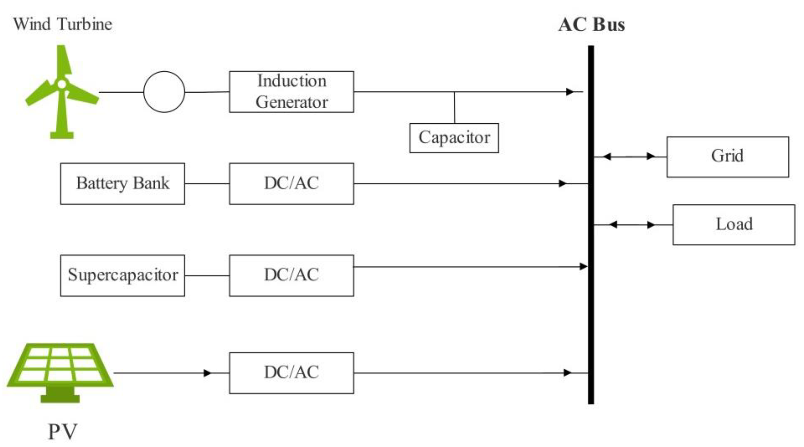
Figure 1. The studied grid structure.
Sustainability 14 06183 g001
Figure 2. Schematic of a typical squirrel cage for a wind-turbine system.
Sustainability 14 06183 g002
Figure 3. Battery nonlinear model.
Sustainability 14 06183 g003
Figure 4. Suggested equivalent circuit for supercapacitor in reference.
Sustainability 14 06183 g004
Figure 5. Configuration of supercapacitor and VSC control system.
Sustainability 14 06183 g005
Figure 6. DC–DC chopper-control system.
Sustainability 14 06183 g006
Figure 7. Calculation of reference powers for the battery and supercapacitor systems to reduce power fluctuations.
Sustainability 14 06183 g007
Figure 8. Control block diagram for battery-power-level management.
Sustainability 14 06183 g008
Figure 9. Reactive-power control system diagram block.
Sustainability 14 06183 g009
Figure 10. The proposed control block diagram.
Sustainability 14 06183 g010
Figure 11. Wind-speed variations.
Sustainability 14 06183 g011
Figure 12. Wind-turbine-power system, photovoltaic system, and grid power (in the presence of a load of 3 KW).
Sustainability 14 06183 g012
Figure 13. Injection power of energy-storage systems based on the proposed control system.
Sustainability 14 06183 g013
Figure 14. Comparison of the power of the battery-energy-storage system and its reference power.
Sustainability 14 06183 g014
Figure 15. Comparison of injection power of the supercapacitor energy-storage system and its reference power.
Sustainability 14 06183 g015
Figure 16. Active grid power before and after compensation.
Sustainability 14 06183 g016
Figure 17. Grid reactive power before and after compensation.
Sustainability 14 06183 g017
Table 1. PI controllers’ parameters.
PI-1PI-2PI-3PI-4PI-5
Kp10.110.11
Ti0.020.0020.020.0020.02
Publisher’s Note: MDPI stays neutral with regard to jurisdictional claims in published maps and institutional affiliations.