Article

Assessment of the Landfill Barrier System through Numerical Analysis: Rehabilitation and Expansion of Belgrade Landfill Case Study

Institute of Geotechnics, Brno University of Technology, Veveri 331/95, 602 00 Brno, Czech Republic
*
Author to whom correspondence should be addressed.
Sustainability 2022, 14(13), 7647; https://doi.org/10.3390/su14137647
Submission received: 28 April 2022 / Revised: 20 June 2022 / Accepted: 21 June 2022 / Published: 23 June 2022
(This article belongs to the Special Issue Studies on Sustainable Rehabilitation of the Built Environment)

Abstract

:
There are still many unmanaged landfills around the world that pose significant potential environmental problems. One of the largest unmanaged landfills in Europe, which has been used for more than 40 years to deposit waste from Serbia’s capital, Belgrade, is the Vinča landfill. A revitalization and extension of this landfill was proposed that would allow its sustainable operation in the future. The revitalization project considered building a capping layer on the surface of the current landfill, which will close it and which will serve as a liner on the bottom of the new landfill. The use of a composite system including a HDPE geomembrane is considered in the project. New landfill settlements were predicted using the FEM method utilizing a Hardening-soil constitutive model for subgrade. Both immediate settlements of subgrade caused by waste deposition and primary consolidation settlement were calculated. The results show that a substantial increase in the settlement of the geomembrane subgrade can be expected during the primary consolidation period, due to the high rate of filling compared to the permeability of the subgrade. The total settlement of the new landfill in its crown is expected to be between 2.73 and 4.52 m. The axial force in the geomembrane will not exceed the tensile strength of the membrane at any time during or after the new landfill operation.

1. Introduction

The construction of engineered landfills is necessary for municipal solid waste (MSW) disposal [1]. By the end of the 1970s, landfill practice was generally unaffected by engineering, and there was little concern about the environmental effects of MSW disposal. Operation of the landfills typically consisted of the uncontrolled backfilling of natural valleys or abandoned open pit mines [2]. The spread of leachate (formed by the seepage of rainwater through the landfill body) into the subsoil was accepted as a common side effect of landfilling. It was assumed that the concentrations of all contaminants transported from the landfill to groundwater would be reduced to safe levels by dilution processes [3,4]. Nevertheless, the dilution processes do not alter the chemical nature of the contaminants or contaminated soil in any manner. Dilution simply decreases the concentrations of contaminants in the leachate [5]. Most landfills that operated with contaminant dilution were consequently declared to be potentially hazardous to the environment [6]. Vinča landfill, which began operation in 1977, is a typical example of the approach described above. The 130-hectare site (which is approximately the same size as 180 football fields) has never been officially operated as a landfill. Therefore, basic facilities, such as a drainage system, have never been developed there [7]. The MSW was dumped in the Vinča landfill area (see Figure 1), which consists of the natural valley of the Ošlian stream, without taking any technical measures at the bottom of the site to prevent the leachate from escaping and being transported through the Ošlian stream outside the landfill area. The risk of contamination of the nearby Danube River with leachate was increased after the 2014 earthquake, which initiated a series of landslides on the slopes of the landfill [8,9]. Millions of Belgrade’s citizens were endangered by a methane-stimulated fire in 2017 [10].
In the 1990s, the principles of landfilling shifted towards total containment, and waste disposal by landfilling incorporated far more highly engineered processes [6]. Currently, the progressive filling of 2 to 3 m high individual cells, formed by very low permeability soil, is preferred. It is not possible to make a landfill completely impermeable according to current knowledge, and so it is preferred to control possible leakages rather than trying to eliminate them completely [11]. Therefore, waste is deposited within pre-constructed containment areas equipped with the appropriate design measures, such as a low-permeability lining system, underdrainage/leachate detection system and leachate drainage and control system. Therefore, the construction and restoration of a landfill site is a major civil engineering project with a high level of geotechnical content [6].

1.1. Vinča Landfill Rehabilitation and Expansion Plans

The current condition of the Vinča landfill imposes a need for a planned rehabilitation solution, and for the expansion of the existing landfill in accordance with good international practice [12,13]. Due to the potential serious environmental hazards [14], the local authorities decided to redevelop the existing landfill. The project of landfill rehabilitation represents a fundamental change in the management of municipal waste in Belgrade [7]. The so-called Energy-From-Waste Facility project was designed as part of the Waste Management System for the City of Belgrade. It is a private–public partnership established to improve the current solid waste disposal practice [15]. It includes remediation of the existing landfill; the construction of a new sanitary landfill; the energy from a waste facility being used to produce electrical and thermal energy; a leachate collection system and treatment plant; a landfill gas collection system that will replace a portion of the imported natural gas [16,17] and be used in a cogeneration plant for the production of electricity and heat [18,19]; and the building of a construction and demolition waste processing plant [20].

1.2. Geotechnical Aspects of the New Vinča Landfill Project

An important detail of the proposed remediation works is the landfill containment system, which will separate the area of closed landfill horizontally from the area of new landfill. The landfill containment system should perform the following functions: (1) prevent leachate from seeping out of the landfill area and thus prevent groundwater contamination [21], (2) prevent landfill gases from leaking and collect them, so that they can be further effectively reused or rendered harmless, (3) remain stable and operate efficiently for the required design lifetime, (4) ensure that the completed landfill does not fill up with water, which would cause a leachate overflow. To achieve these objectives, landfill sites are lined with mineral layers or synthetic membranes, or with a combination of both. Clay liners are inherently more permeable than synthetic membranes. The use of clay liners can also be problematic, because the smectite components of bentonite liners interact chemically with leachate, which leads to a decrease in their swelling capacity and an increase in hydraulic conductivity. Therefore, they lose their sealing function over the course of their lifespans [22]. However, it is difficult to protect synthetic membranes from damage. This, together with uncertainty about the long-term durability [23,24] and degradation of synthetic lining systems in a harsh chemical environment at the base of the landfills [25,26], increases the possibility of liner failure at some stage in the future when the waste is still active, leading to groundwater pollution by landfill leachate [22,27]. There is no single ideal liner material. Composite mineral/geomembrane systems, including two separate barriers made of different materials, are thus combined to provide a synergistic effect. Such a composite system provides the highest degree of security against leakage [28].
The landfill containment will have two main functions in the Vinča landfill project. It will serve as the liner at the base of the new landfill, and simultaneously, as the final cover for the finished old landfill. This provides a major engineering challenge, as the barrier layer must be able to resist both the stresses caused by differential movements and settlements of the subgrade and loading by the MSW deposited on the new landfill. The planned rehabilitated and extended Vinča sanitary landfill will be located in part over the existing landfill (approximately 45% of the area), and on the ground surrounding the existing landfill (approximately 55% of the area). Among other factors, the design engineer must consider the subgrade bearing capacity required for landfill [29]. The bearing capacities of the two types of new landfill subgrade are different. The higher compressibility of the subgrade composed of untreated municipal waste, which is an extremely heterogeneous material with variable permeability and water retention properties, causes higher settlements when compared to the subgrade composed of naturally deposited soils. In the extreme case of settlement, an unwanted pooling of water may occur, or surface water may leak into the underlying waste through cracks in the liner [6]. Differential settlements in barrier systems can also induce strains in the geomembrane [30]. Great emphasis has to be placed on the design of the components and materials of the liner [31,32] to sustain deformations induced by differential settlement [33], and also by loading, traffic from filling vehicles, [34] etc. Deformation of the membrane is therefore affected by a number of variables, some of which are dependent on others. Thus, predicting, measuring, assessing, and determining acceptable limits of membrane strains poses a challenge for designers [30,35], and a number of studies tried to assess strain in geomembranes experimentally [36,37,38,39].
The settlement of MSW placed above the containment system also affects tensile stresses in the geomembrane significantly by down-drag effect. Hence, the geometry of the anchor trench to prevent the sliding of the membrane down a slope was designed according to Koerner and Soong [40] and was also modelled. Several researchers, e.g., [41,42,43,44], have formulated different constitutive models for the mathematical description of the MSW stress–strain relationship recently [45], with various level of accuracy of settlement prediction. Currently, new constitutive models are still being developed by researchers in response to advances in understanding the processes that occur over time in the decomposing MSW. Some researchers consider the effects of mechanical creep [46] and time-dependent biodegradation [47,48] to predict total landfill compression under incremental loading and with time. Machado et al. [47] introduced a mathematical concept based on two MSW components—fibers and organic paste. Machado’s model considered reduction of the ultimate tensile stress and the Young’s modulus of MSW and the mass loss caused by the organic component degradation over time. Models developed by Sivakumar Babu et al. [49] and upgraded later by Feng et al. [48] are based on the framework of critical state soil mechanics. The proposed constitutive model [49] incorporates increments in volumetric strains caused by elastic, plastic, time-dependent biodegradation, and mechanical creep effects, where the dependence of biodegradation is governed by an empirically determined exponential function. Feng et al. [48] followed up on the work of Sivakumar Babu et al. [49] by formulating the volumetric strain governed by the biodegradation-induced void change parameter. The most recent constitutive model by Wu Gao and Edward Kavazanjia Jr. [46], published in 2022, also utilizes the critical state soil mechanics framework to describe the stress–strain–time behavior of MSW over time. The hardening of the MSW in this model is considered to be a result of time-independent plastic volumetric strain, time-dependent volumetric mechanical creep strain and time-dependent volumetric strain resulting from the decomposition of MSW. Despite the theoretical precision of some of these models, the predicted stress–strain relationship can vary significantly depending on the model used and the parametric values selected, as was shown by Sivakumar Babu et al. [49]. They compared settlement predictions using 14 different models. The results varied between 0.8% and 67% of initial thickness of the MSW layer [49]. The MSW settlement levels caused by the mechanical compression and decay of biodegradable components were in the range of 25% to 50% of the initial thickness of the layer [50,51,52,53]. If no better alternative to the description of the stress–strain relationship for MSW is available, an interim quasi-geotechnical approach can be accepted [6]. For older landfills, most of the MSW settlement takes place in the first five years after waste is deposited. Total settlement values are then usually reached within thirty years [54,55]. The filling and closure of landfills is now much more rapid than in the past. Therefore, the time to reach total settlement can be expected to increase to about 100 years. Around 80% of the total settlement can be expected within 30 years [56].
Within the preliminary phases of the rehabilitation and expansion design of the Vinča landfill project, it was necessary to reasonably analyze the response of the geomembrane subjected to induced differential settlement of the subgrade progressively loaded with new layers of waste. This paper describes the mathematical modelling procedure performed for this purpose, including the determination of the input parameters of the material models (Hardening Soil and Mohr-Coulomb) used. The settlement in the plane of the new landfill ground zone and the axial force in the geomembrane were calculated and evaluated. (The axial force states for the force in the longitudinal (in-plane) direction of the geomembrane.) The consolidation processes in the subgrade and in the MSW were also modelled [35], with respect to the real planned filling stages of the new landfill.
The strength of the contact between the geomembrane and the adjacent layer was also analyzed, as it influences the resulting tensile forces in the geomembrane. Stronger contact results in lower calculated axial forces in the geomembrane. The strength of contact depends on the choice of geomembrane protection layer and the type of gravel aggregate used in the drainage layer. Although a uniform aggregate is preferred from a drainage perspective, it is undesirable in terms of geomembrane strain [30,57]. The significance of interface shear strength on the results can be seen in the many papers published on this subject. This phenomenon was analyzed by laboratory testing [58,59] mostly in direct shear apparatus and also numerically [60,61]. Discussions of many numerically and experimentally obtained results were published, e.g., by Palmeira [62] and by McCartney et al. [63]. The sensitivity of interface shear strength to the type of polymer used for geomembrane production, the geomembrane texturing and the type of clay liner was observed [63].

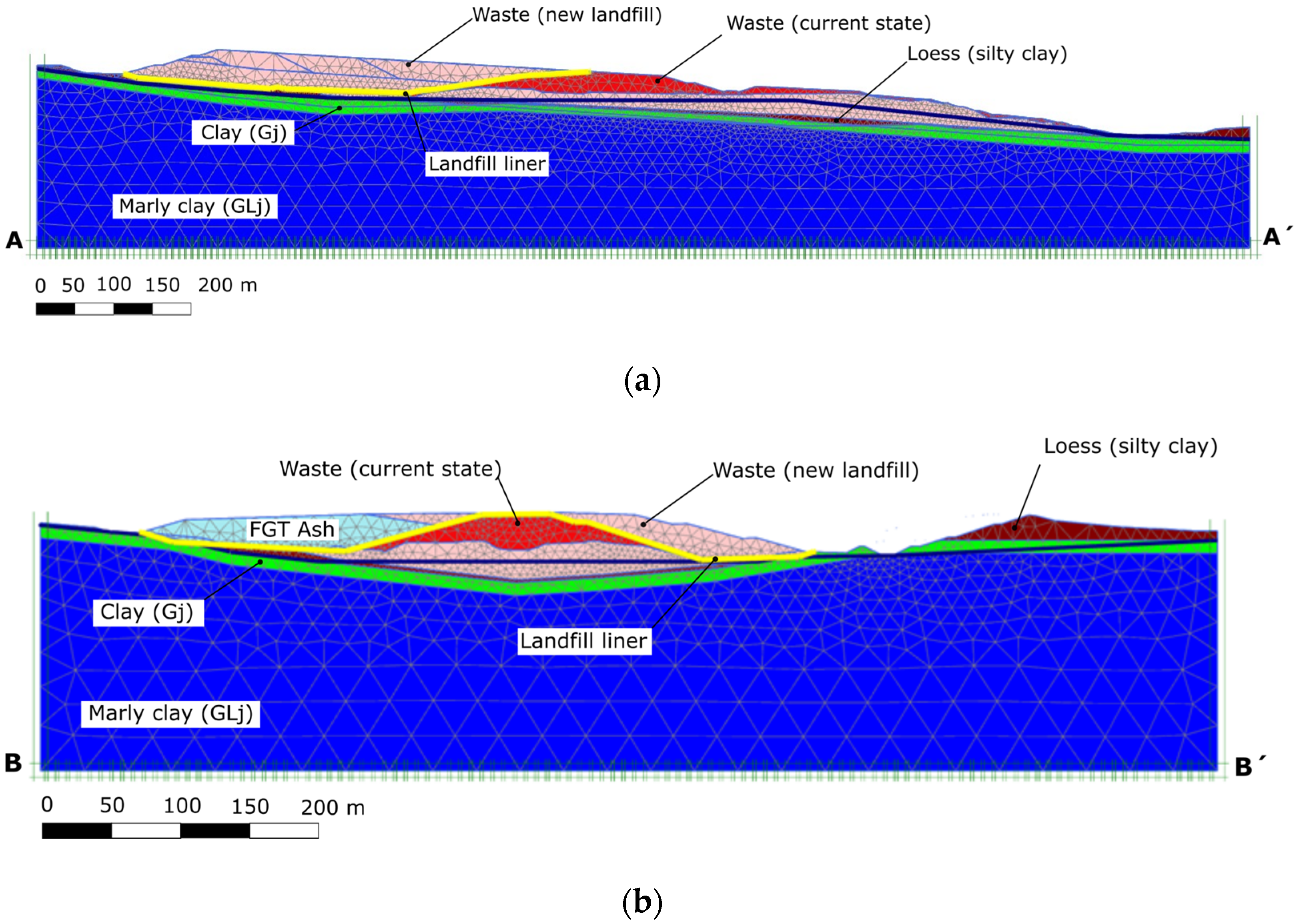
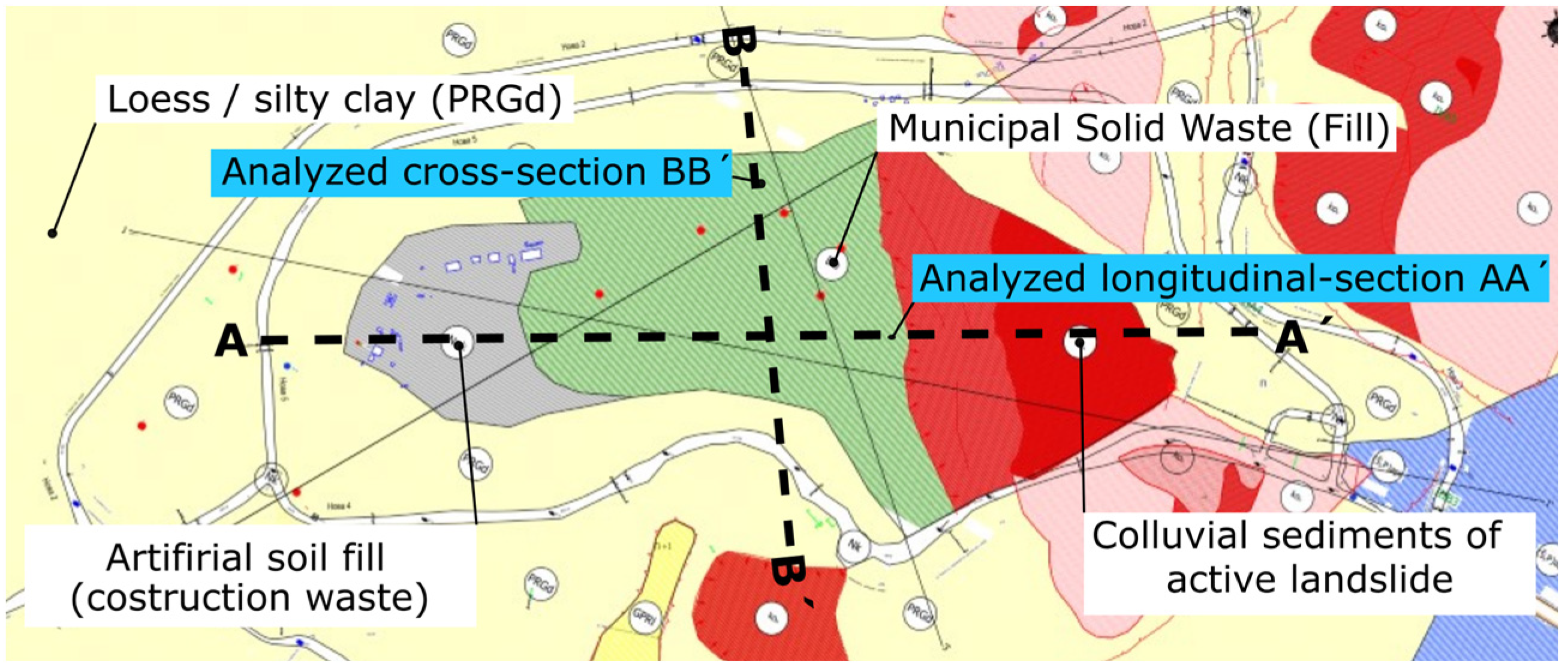
2. Geological and Geotechnical Conditions on the Site

The body of the planned new landfill will extend over both the existing landfill and over the areas adjacent to the existing landfill. For the design of the liner, it was therefore necessary to determine the mechanical and hydraulic parameters of both the original soil and the MSW deposited so far. The lithological boundaries of the subsoil layers of the landfill were modelled according to the description of the boreholes described in an engineering geological survey report [64]. The boreholes described in the report [65] and the description of the excavated probes and dynamic penetration probing result summarized in the survey [66] were also considered.

2.1. Natural Soil Description

After landscaping, the ground zone of the new landfill will be in contact with a layer of cohesive quaternary and tertiary soils. Quaternary soils are mainly represented by aeolian sediments, i.e., loess and silty clays (PRGd) deposited over the layer consisting of diluvial silty-sandy clays (Gj). These two types of soils have similar geotechnical properties: They are predominantly composed of silty particles and have variable admixtures of fine to medium sand. The soils have medium plasticity, or sometimes high plasticity. There is often a calcareous component present in the loess, either as concretions or as silty particles. Soils of both types of genesis are classified as F6-CI, and less often as F8-CH according to Unified Soil Classification System (USCS). An engineering geological map of the quaternary cover showing the main geotechnical types and the positions of the modelled sections is shown in Figure 2.

2.2. Hydrogeological Conditions at the Site

Groundwater level fluctuations were measured using exploratory probes over time. Below the surface of the existing landfill, it was detected at depths ranging from 1.7 to 14.9 m, most commonly 3 to 8 m. The differences may be due to the inhomogeneity of the deposited material, as a continuous aquifer is not formed, but isolated aquifers are allowed to form at different elevations. The groundwater level in the naturally deposited layers not affected by landfilling was found at a depth of 7.5 to 11.5 m below ground in the western and southern areas, and in the south-eastern part at a depth of 3.3 to 3.8 m. Based on the depths of the groundwater table, the requirement is met for it being 1.0 m or deeper underground of the landfill.

3. Numerical Calculation Assumptions

Numerical analysis was performed using the finite element method. Plane strain models were created using Plaxis 2D 2016.01 (Build 5460) [67]. Fifteen-noded triangular finite elements with the fourth-order interpolation of displacement were used. In this paper, we present two selected mathematical models: one cuts the area of interest longitudinally and the second one transversely. The dimensions of the mathematical models and the numbers of the of finite elements and nodes generated are summarized in Table 1.
The mathematical models with indications of materials and with finite element mesh displayed are schematically shown in Figure 3.
The influence of the value of the strength reduction factor Rinter on the results was also studied. The composite liner was approximated by a geogrid type of finite element representing the geomembrane in the models. The reduction factor Rinter reduces the shear strength parameters of the linear elastic—perfectly plastic material model of the contact element. If relative movement occurs between the soil and geosynthetic layer (or between two geosynthetic layers), the shear strength in the soil–geosynthetic (geosynthetic–geosynthetic) interface is mobilized. In the cases of geomembranes and geotextiles, the interaction mechanism mobilized on the interface is the skin friction. When the shear strength of the interface is exceeded, the failure occurs by direct shear. The effective strength parameters of the interface elements (ci, tan φi) are given by Equations (1) and (2), where ci and tan φsoil are the effective strength parameters of the soil surrounding the interface element. The same principle is applied when the soil strength is defined by the undrained shear strength su,soil (Equation (3)).
tan φ i = R inter tan φ soil
c i = R inter c soil
s u , i = R inter   s u , soil
It must be noted that the Rinter factor also influences the interface stiffness, and consequently, the displacements parallel to the interface (ut) and perpendicular to the interface (un):
u t = τ t i R inter 2 G soil
u n = σ n t i 2 R inter 2 G soil 1 2 ν i 1 ν i
where τ and σn are the current shear and normal stress, respectively; Gi is the shear modulus of the interface; Eoed,i is the one-dimensional compression modulus of the interface; ti is the virtual thickness of the interface; and νi is the Poisson ratio of the interface.
The numerical simulations were carried out in steps that relate to the planned waste disposal procedure in the new landfill area over the period of its operation. The sequences of calculation steps are summarized in Table 2 and Table 3.
The minimum excess pore water pressure value of 1 kPa was chosen as the criterion for the end of consolidation in the last calculation phase for both models.

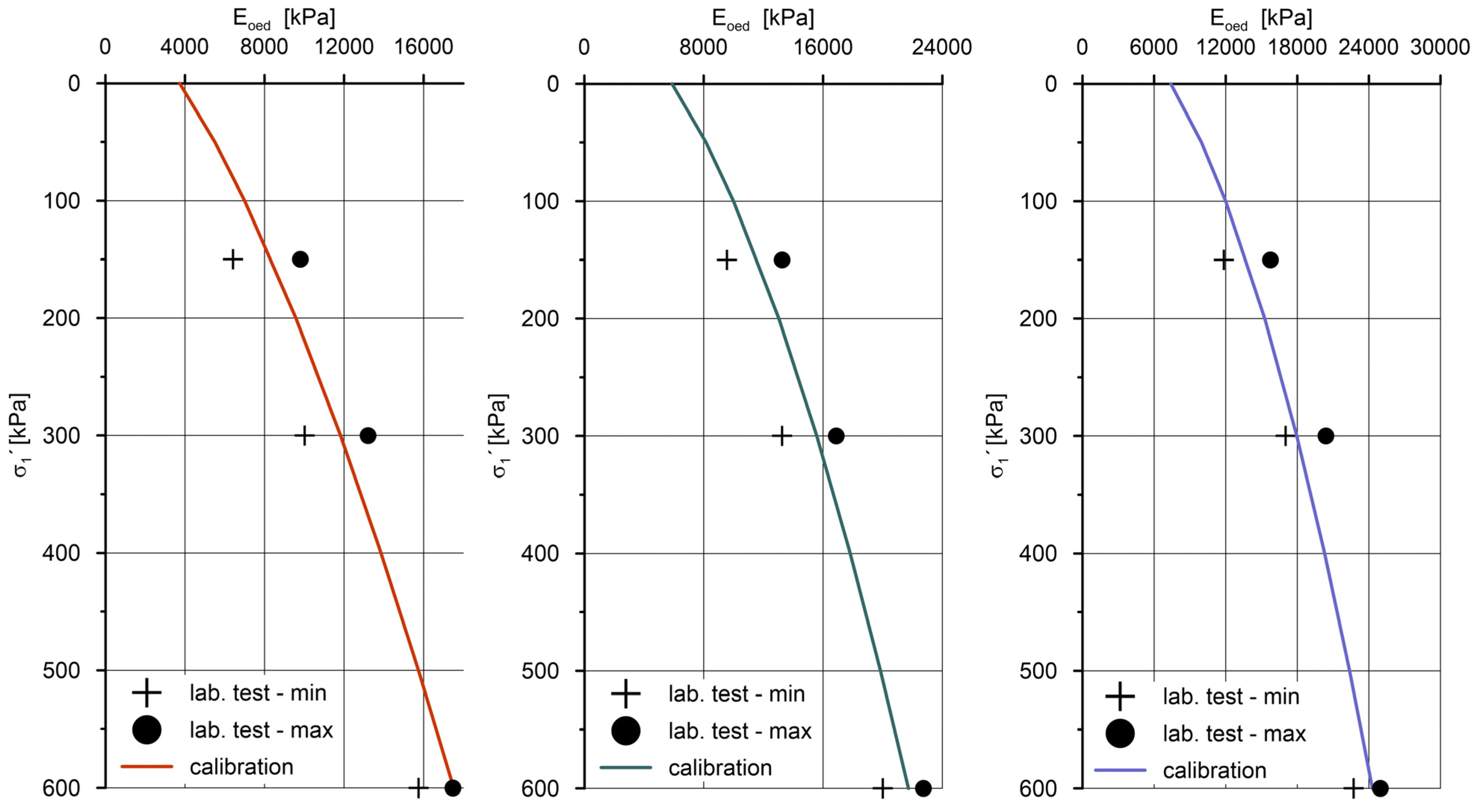
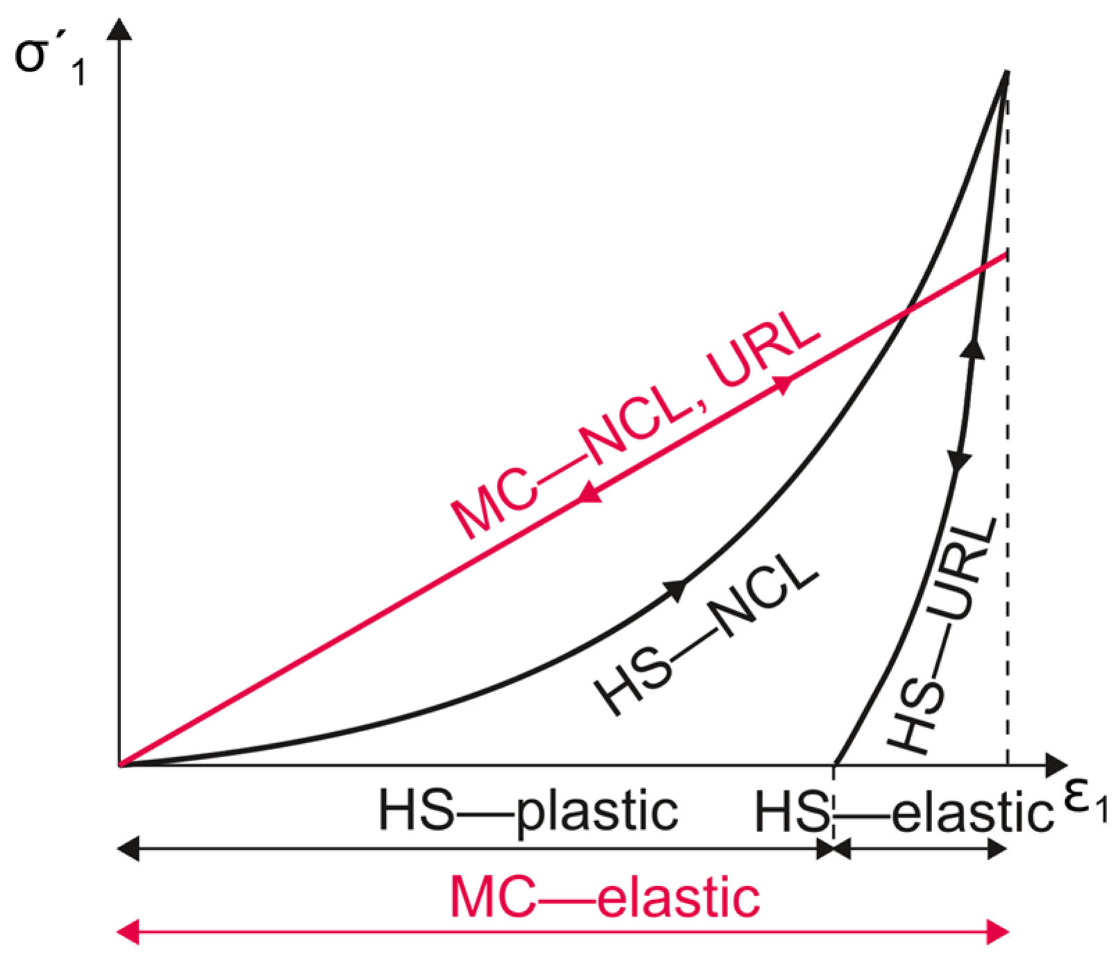
3.1. Material Models Used in Simulation

The constitutive model, or material model generally, shows the relation between two physical quantities that is specific to a material. The material model in the mathematical analyses in this paper describes the relation between stress increment and strain increment. Two material models were utilized throughout the analyses to describe soils and MSW:
  • The linear elastic—perfectly plastic Mohr–Coulomb MC model (MC);
  • The Hardening Soil Model (HS)—an elastoplastic model with shear and volumetric hardening [68].
The MC model was used to describe the MSW and a soil used to modify the terrain before the liner installation. The HS model was used to simulate the behavior of the subgrade layers. The definition of HS model was based on the non-linear (hyperbolic) relationship between axial strain and the deviatoric strain in pioneering works [69,70]. These non-linear elastic constitutive models were later complemented by shear and compression yield surfaces. Non-associated plasticity was adopted in the case of shear hardening. The associated plasticity was utilized to predict plastic volumetric changes during compression hardening. The basic features of both material models are graphically compared in Figure 4 and Figure 5 for isotropic and deviatoric loading, respectively.
NCL and URL stand for the normally consolidated line and the unloading–reloading line. E is the modulus of elasticity adopted in the MC model. The response of the HS model is governed by three stiffness parameters: E50 is the secant stiffness in the standard drained triaxial test, Eur is the unloading/reloading stiffness, and Eoed is the tangent stiffness for the primary oedometer loading. All stiffness modules are stress-dependent; thus, their values for the reference stress level pref present inputs for the material model.
Eoed is important in the displacement analysis of large embankments, and therefore, the adopted stress–stiffness formulation is stated below. The friction angle φ and cohesion c are the shear strength parameters, m is the power for the stress-level dependence of stiffness, and K0nc is the K0 value for normal consolidation (K0nc = 1 – sin φ ):
E oed = E oed ref ( c ´ cos φ ´ σ ´ 3 K 0 nc sin φ c ´ cos φ ´ + p ref sin φ ) m
The performed analyses account for not only the plastic deformations inferred by waste disposal loading, but also for the consolidation processes associated with the dissipation of excess pore pressures in the geological layers underlying the landfill. The consolidation is a coupled hydro–mechanical problem. The change in porosity is influenced by the change in the effective stress state, which means that a hydraulic problem is influenced by a mechanical problem. On the contrary, the change in pore pressures, and hence the effective stresses, is controlled by the hydraulic model, which means that the mechanical model depends on the hydraulic one. Both the equilibrium conditions and continuity equations are linked and solved simultaneously:
[ K L L T S ] [ dv dt dp n dt ] = [ 0 0 0 H ] [ v p n ] + [ df n dt q n ]
where K is the stiffness matrix, L is the coupling matrix, S is the compressibility matrix, H is the permeability matrix, ν is the nodal displacements vector, pn is the nodal excess pore pressure vector, fn is the incremental load vector, and qn is the vector due to the prescribed flow at the boundary.
An elastoplastic material model [71] was used for the description of the stress–strain dependence in the geogrid element simulating the liner. The axial stiffness of the geogrid element EA1 = 309 kN/m and the characteristic tensile strength Np,1k = 34 kN/m were determined according to [72]. The characteristic value was decreased by a reduction coefficient RFCR = 1.5, which considers the creep behavior of the material. The design value of the tensile strength after this adjustment is Np,1d = 22.6 kN/m.

3.2. Input Values of Soil and Waste Material Parameters
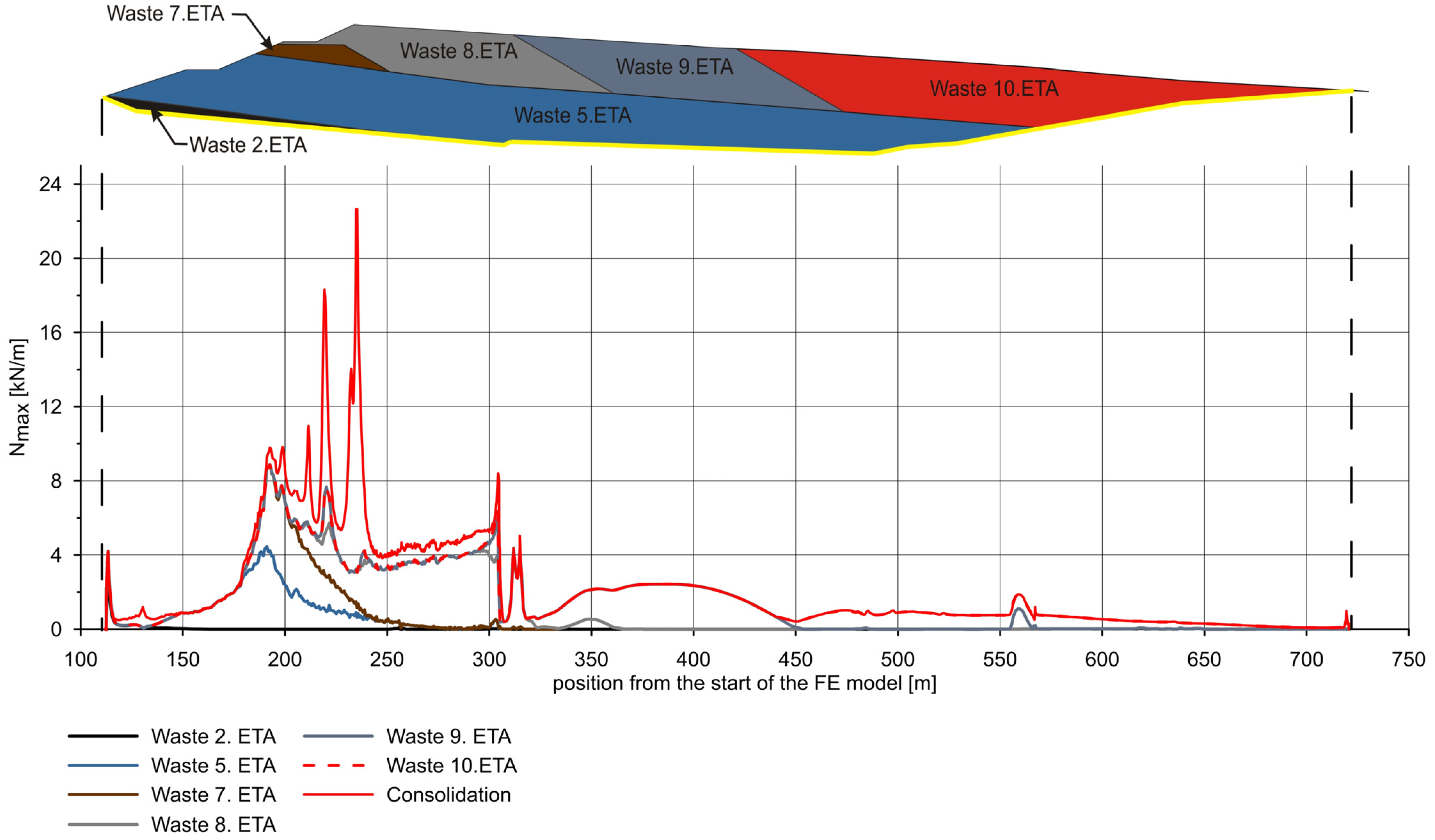
A summary of the key engineering parameters of MSW can be found in the literature [73]. MSW consists of different types of materials that are different in their mechanical and chemical properties. Some of these materials decompose over time through ongoing chemical and biological processes, while the properties of others do not change. The classical concepts of soil mechanics themselves have limitations in the modeling of such a complex material as MSW [74]. However, many studies show that, despite the heterogeneous nature of the waste, its mechanical properties change predictably depending on the stress state [73]. This can be observed, for example, in the increasing stiffness of MSW confirmed by dynamic probing performed during surveying of the landfill. (Note: in situ methods can generally be considered very suitable tools for the investigation of landfills [75], whose characteristics can vary considerably in space). The results of probing are mentioned in the following paragraph.
The thickness of MSW was determined by the heavy dynamic probing to be between 3.9 and 29.6 m. The stiffness was also determined based on the above-mentioned penetration tests. In the upper layer of the deposited MSW, which is up to 5 m thick where the waste has not yet been homogenized by biochemical processes and its subsequent consolidation, the E oed ref values vary in the range of 5 to 15 MPa (with one outlier E oed ref   = 64 MPa probably caused by the presence of a locally buried obstacle composed of material of relatively higher stiffness). In the deeper part of the landfill, the E oed ref values range between 10 and 20 MPa. The single value E oed ref = 10 MPa was considered in calculations, which seems to be reasonable in terms of fitting within the intervals of the measured values and which is also on the safe side in terms of calculating the MSW settlements. The unit weight of municipal solid waste is also an important parameter in engineering analyses of landfill performance, but there is currently significant uncertainty about its value. The data show that individual landfills have characteristic unit weight profiles [76,77]. The bulk density of MSW depends on its specific gravity [78] and the degrees of decomposition and compaction. The values of 1000 to 1200 kg/m3 were considered in the present case according to the relationship based on the critical review of published field research data [76]. It is possible to find the results of shear box tests [6] in the literature aimed at determining the shear parameters of waste [6], e.g., [79,80]. Although MSW is an inherently variable substance, the published values of the shear strength parameters appear to be relatively consistent. Values between 0 to 30 kN/m2 for cohesion and the range of 20 to 35 degrees for a friction angle can be considered reasonable for design purposes according to [6]. The values of effective strength parameters of the MSW determined according to the results of the undrained full-scale shear test published in [81] were considered in the presented analysis and are summarized in Table 4. Determining the filtration coefficient of MSW also poses a major challenge, as it is largely dependent on pore structure, which is directly affected by compression stress and degradation [82,83,84,85]. Based on the published results of an extensive review of the characteristics of landfilled MSW in several countries [86], the values of the permeability coefficient range from k = 3.5 × 10⁻⁴ to 5.0 × 10⁻¹⁰ m/s, which is also consistent with the results of other researchers [87,88]. The value of the permeability coefficient k = 1.0 × 10⁻⁵ m/s was considered in the presented analyses, which is in accordance with the above referenced studies. In addition to MSW, the disposal of flue gas residues, namely, solidified fly ash (FGT), is also planned in an area of the newly constructed landfill. The mechanical and hydraulic parameters of solidified fly ash FGT used in the presented paper were taken from [89]. The values of strength, hydraulic and index parameters of materials used in analyses are summarized in Table 4.
The reference value of tangent stiffness for primary oedometer loading E oed ref and the m parameters that govern the stress-level dependency of stiffness according to Equation (6) were determined based on available 1D compression tests. Graphs of the increase in stiffness with the effective normal stress based on the laboratory test results for natural soils are shown in Figure 6. The results of odometric tests [64] do not show an overconsolidation of the soils tested. Therefore, the values OCR = 1 and POP = 0 kPa were considered in the analysis. The input values of the stiffness parameters of the materials used in the model are summarized in Table 5.

4. Results

The axial force in the geomembrane and the settlement measured at the level of the liner were calculated for each phase. Graphs with the values of these variables plotted along the length of the analyzed individual section are shown in Figure 7, Figure 8, Figure 9, Figure 10 and Figure 11. Only the settlement of the subgrade induced by the load of the newly deposited waste is relevant for the evaluation of the new landfill liner. Therefore, the settlement graphs show only the sum of vertical deformations starting from phase 4, which simulates the installation of the liner in the analyses.
Reducing the shear strength of the geomembrane–soil interface Rinter = 0.5 caused the shear strength of that interface to be reached in the section between 170 and 250 m from the start of the model. This was reflected in the occurrence of unrealistic axial force oscillations during the consolidation stage (Figure 8).
Figure 9 shows that the rate of filling is significantly higher than the permeability of the underlaying layers would allow. Therefore, a substantial increase in settlement during the period of primary consolidation can be expected. The increase in axial forces in the geomembrane is mainly due to a non-uniform layering of a waste material. According to the Figure 7, the change in the axial forces during consolidation is small when compared to the phase of waste deposition.
The settlement of the crown of the newly built landfill utot = 4.52 m in the case of the model of longitudinal section A–A′ and utot = 2.73 m in the case of the cross-sectional model B–B′ were calculated at the time after the minimum excess pore pressure 1 kPa was reached.

5. Discussion

Settlement is one of the main factors for the development of tensile stresses in the geomembrane in landfill applications. Recently, studies have been published that investigate the development of tensile strains in the geomembrane using the FEM method [46,90]. The landfills modelled in these studies simulated ideal conditions for the setting and filling of new landfill. This means that the subsoil of the modelled landfills is made of competent rock and the waste is deposited in a controlled manner in evenly distributed layers. In some areas, it is sometimes inevitable to build landfills on soft subgrade settlement. In Xu et al.’s paper [91], such a landfill with a flat bottom was analyzed. If a new landfill project is being developed, a suitable site is selected for its construction and filling is properly managed further. However, this may not always be the case for existing landfills. Some case studies regarding the redevelopment of MSW landfills were published, e.g., [92,93], but they are not based on numerical modeling. The purpose of this paper was to numerically analyze a real-life case with initial geological and geometrical conditions predetermined by the previous development of an originally unmanaged and subsequently rehabilitated landfill site considering the realistic filling plan and to analyze results influenced by these conditions.
The results of the numerical analyses showed that the expected axial force does not exceed the design strength Np,1d = 22.6 kN/m of the geomembrane planned to be incorporated into the composite liner. A significant increase in the axial force can be observed where the liner transitions from the area of the current landfill to the area of the extended landfill (see, e.g., the section between 175 and 250 m from the start in the mathematical model B–B′ in Figure 8). In other words, the peak values in the axial force are observed in the sections where the subsurface properties change abruptly. The increases in axial forces in the geomembrane are also due to non-uniform layering of MSW given by the filling plan prescribed by the landfill operator.
The influence of the value of the strength reduction factor Rinter on the results was also evaluated. Without the strength reduction (Rinter = 1.0), the maximum axial force 7.2 kN/m was calculated in the model of longitudinal section A–A′. Reducing the shear strength of the geomembrane-soil interface caused the shear strength to be reached in the section between 170 and 250 m in the mathematical model of cross-section A–A′. This was reflected in the occurrence of unrealistic axial force oscillations during the consolidation stage of calculation. The actual Rinter value selection considers the weakest interface in the geomembrane–geotextile–drainage layer system. From these three interfaces, the geomembrane–geotextile contact is usually the weakest one. As the final choice of the composition of the sealing layer was not made in the initial phase of the project, it was not possible to perform an analysis with a particular value of Rinter. Since the value of Rinter affects the stresses induced in the geomembrane, further research regarding the modeling of this detail is still required.
As part of the preliminary considerations for the use of the area of the planned landfill after it has finished operation in the future, it should be considered that settlement at the level of the future landfill crown will be in the order of meters (utot = 2.7 m to utot = 4.5 m in the cross-sections presented). Most studies are concerned with the settlement of the MSW layer itself, but not with the settlement of a subgrade. As the results of the analyses conducted show, subgrade settlement can be a non-negligible component of total settlement. The settlement of only subgrade uy = 3.75 m in the case of longitudinal section A–A′ represents 83% of the total settlement utot = 4.52 m, including the settlement of a 47 m thick MSW layer. This value is dependent on the constitutive model used for the description of the MSW behavior within the analysis. If the settlement of the MSW layer to the order of 25% to 50% of the initial thickness was theoretically considered, as reported by the results of referenced studies [49,50,51,52,53], the settlement of the originally 47 m thick layer would be uMSW = 11.75 m or uMSW = 23.5 m, respectively. Still, the total settlement of subgrade uy = 3.75 m would represent 32% of theoretical total settlement or 16%, respectively. Moreover, the settlement distribution is highly non-uniform along the cross-sections, due to the non-evenly deposited MSW layers.
According to the referenced literature, 80% of the settlement of MSW layer should take place within the first 30 years after its deposition. Compared to the time needed for the settlement of the MSW, the time for reaching the final primary consolidation settlement of subgrade is longer. Only 25% of primary consolidation settlement of subsoil is expected to be reached during the 28 years of operation of the new landfill in the case of cross-section B–B′, and 27% in the case of cross-section A–A′.
Deformations of the subgrade beneath the landfill body also result in uplifting of the terrain at the landfill perimeter during the filling and in a settlement during the consolidation phase. Thus, a fixed position of the anchor trench in the space that is assumed in analytical methods for the design of anchor trenches is not guaranteed.
The synergistic effect of MSW settlement and the settlement of the landfill subgrade on membrane stresses requires further studies, adopting eventually different constitutive models for MSW and different strength reductions of the interface between the geomembrane and adjacent materials.

Author Contributions

J.Š. prepared the mathematical models and took part in performing calculations. J.Š. wrote the manuscript. J.C. calibrated the input parameters for simulations. J.C. also took part in performing calculations and visualized the results of analyses. All authors have read and agreed to the published version of the manuscript.

Funding

The APC was funded by the EU’s programme Erasmus+ project KA2—Higher education strategic partnerships number 2018-1-RO01-KA203-049214, “Rehabilitation of the Built Environment in the Context of Smart City and Sustainable Development Concepts for Knowledge Transfer and Lifelong Learning”—RE-BUILT.

Institutional Review Board Statement

Not applicable.

Informed Consent Statement

Not applicable.

Data Availability Statement

Not applicable.

Acknowledgments

The authors thank Petr Moric from the company Aqautis Ltd. for providing the engineering geological survey reports and for the opportunity to participate in the Vinča landfill remediation project.

Conflicts of Interest

The authors declare no conflict of interest.

References

  1. Ashford, S.A.; Visvanathan, C.; Husain, N.; Chomsurin, C. Design and construction of engineered municipal solid waste landfills in Thailand. Waste Manag. Res. J. Sustain. Circ. Econ. 2000, 18, 462–470. [Google Scholar] [CrossRef]
  2. Cvetkovic-Mrkic, S.; Janjic, I. Environmental aspects of interaction between structures and geologic milieu. In Proceedings of the International Symposium on Engineerin Geology and the Environment, Athens, Greece, 23 June 1997; The Greek International Group of IAEG. Volume 3, pp. 2647–2652. [Google Scholar]
  3. Samadder, S.; Prabhakar, R.; Khan, D.; Kishan, D.; Chauhan, M. Analysis of the contaminants released from municipal solid waste landfill site: A case study. Sci. Total Environ. 2017, 580, 593–601. [Google Scholar] [CrossRef] [PubMed]
  4. Cai, G.; Liu, S.; Tong, L.; Du, G. Assessment of direct CPT and CPTU methods for predicting the ultimate bearing capacity of single piles. Eng. Geol. 2009, 104, 211–222. [Google Scholar] [CrossRef]
  5. Han, Z.; Ma, H.; Shi, G.; He, L.; Wei, L.; Shi, Q. A review of groundwater contamination near municipal solid waste landfill sites in China. Sci. Total Environ. 2016, 569–570, 1255–1264. [Google Scholar] [CrossRef] [PubMed]
  6. Sarsby, R. Environmental Geotechnics, 2nd ed.; ICE Publishing: London, UK, 2013; pp. 231–284. [Google Scholar]
  7. Helping Belgrade Redevelop Its Previously Unmanaged Vinca Landfill, Including New Waste-to-Energy Project. Available online: https://www.arup.com/projects/vinca-landfill-redevelopment-serbia (accessed on 25 April 2022).
  8. Milanovic, A.; Kovacevic-Majkic, J.; Milivojevic, M. Water quality analysis of Danube river in Serbia: Pollution and protection problems. Glas. Srp. Geogr. Drus. 2010, 90, 47–68. [Google Scholar] [CrossRef]
  9. Brboric, M.; Stepanov, B.; Radonic, J.; Turk-Sekulic, M. Danube sediment contamination with polychlorinated biphenyls: New interpretation of sediment quality assessment. Acta Period. Technol. 2019, 43–50. [Google Scholar] [CrossRef] [Green Version]
  10. Sretenović, B.; Arnaut, F.; Vasiljević, I.; Cvetkov, V. 2D geoelectrical resistivity tomography application at the former city waste dump “Ada Huja”: Eco-geological problem. Podzemn. Rad. 2019, 59–76. [Google Scholar] [CrossRef]
  11. Bagchi, A. Design, Construction and Monitoring of Landfills, 2nd ed.; Wiley: New York, NY, USA, 1994; pp. 1–376. [Google Scholar]
  12. Karanac, M.; Jovanovic, M.; Timmermans, E.; Mulleneers, H.; Mihajlovic, M.; Jovanovic, J. Impermeable layers in landfill design. Hem. Ind. 2013, 67, 961–973. [Google Scholar] [CrossRef]
  13. Laner, D.; Crest, M.; Scharff, H.; Morris, J.; Barlaz, M. A review of approaches for the long-term management of municipal solid waste landfills. Waste Manag. 2012, 32, 498–512. [Google Scholar] [CrossRef]
  14. Josimović, B.; Marić, I.; Milijić, S. Multi-criteria evaluation in strategic environmental assessment for waste management plan, a case study: The city of Belgrade. Waste Manag. 2015, 36, 331–342. [Google Scholar] [CrossRef]
  15. Jovanovic, D.; Zivkovic, T. Public-private partnership as a possibility for improving municipal waste management. Spatium 2019, 41–48. [Google Scholar] [CrossRef] [Green Version]
  16. Nikolic, A.; Mikic, M.; Naunovic, Z. Broadening the urban sustainable energy diapason through energy recovery from waste: A feasibility study for the capital of Serbia. Renew. Sustain. Energy Rev. 2017, 69, 1–8. [Google Scholar] [CrossRef] [Green Version]
  17. Lee, U.; Han, J.; Wang, M. Evaluation of landfill gas emissions from municipal solid waste landfills for the life-cycle analysis of waste-to-energy pathways. J. Clean. Prod. 2017, 166, 335–342. [Google Scholar] [CrossRef]
  18. Alivojvodic, V.; Stanojevic, M.; Antonijevic, D. Belgrade solid waste management optimization—Potential of landfill gas recovery. Environ. Eng. Manag. J. 2015, 14, 2979–2984. [Google Scholar] [CrossRef]
  19. Ubavin, D.; Maoduš, N.; Milovanovič, D.; Stege, G.; Leatherwood, C. Preliminary estimate of methane production at Belgrade MSW landfill “Vinča”. In Proceedings of the 6th PSU-UNS International Conference on Engineering and Technology (ICET-2013), Novi Sad, Serbia, 15–17 May 2013. [Google Scholar]
  20. Beo Čista Energija d.o.o. Vinča Energy-From-Waste Facility, Construction of the New Landfill and Remediation of the Existing Landfill: Environmental and Social Impact Assessment, Non-Technical Sumary; Version 6; BC Beo Čista Energia: Beograd, Serbia, 2018; pp. 1–15. [Google Scholar]
  21. Pandey, L.; Shukla, S. An insight into waste management in Australia with a focus on landfill technology and liner leak detection. J. Clean. Prod. 2019, 225, 1147–1154. [Google Scholar] [CrossRef]
  22. Allen, A. Containment landfills: The myth of sustainability. Eng. Geol. 2001, 60, 3–19. [Google Scholar] [CrossRef]
  23. Rowe, R.; Sangam, H. Durability of HDPE geomembranes. Geotext. Geomembr. 2002, 20, 77–95. [Google Scholar] [CrossRef]
  24. Lavoie, F.; Kobelnik, M.; Valentin, C.; da Silva, J. Durability of HDPE Geomembranes: An Overview. Quím. Nova 2020, 43, 656–667. [Google Scholar] [CrossRef]
  25. Abdelaal, F.; Rowe, R.; Brachman, R. Brittle rupture of an aged HPDE geomembrane at local gravel indentations under simulated field conditions. Geosynth. Int. 2014, 21, 1–23. [Google Scholar] [CrossRef]
  26. Rowe, R.; Abdelaal, F. Antioxidant depletion in high-density polyethylene (HDPE) geomembrane with hindered amine light stabilizers (HALS) in low-pH heap leach environment. Can. Geotech. J. 2016, 53, 1612–1627. [Google Scholar] [CrossRef]
  27. Rowe, R.; AbdelRazek, A. Effect of interface transmissivity and hydraulic conductivity on contaminant migration through composite liners with wrinkles or failed seams. Can. Geotech. J. 2019, 56, 1650–1667. [Google Scholar] [CrossRef]
  28. Seymour, K. Landfill Lining for Leachate Containment. Water Environ. J. 1992, 6, 389–396. [Google Scholar] [CrossRef]
  29. Benson, C.; Daniel, D.; Boutwell, G. Field Performance of Compacted Clay Liners. J. Geotech. Geoenviron. Eng. 1999, 125, 390–403. [Google Scholar] [CrossRef]
  30. Marcotte, B.; Fleming, I. Design guidance for protection of geomembrane liners in landfill applications. Can. Geotech. J. 2022, 59, 743–757. [Google Scholar] [CrossRef]
  31. Gupt, C.; Bordoloi, S.; Sahoo, R.; Sekharan, S. Mechanical performance and micro-structure of bentonite-fly ash and bentonite-sand mixes for landfill liner application. J. Clean. Prod. 2021, 292, 126033. [Google Scholar] [CrossRef]
  32. Zhang, T.; Cai, G.; Liu, S. Assessment of mechanical properties in recycled lignin-stabilized silty soil as base fill material. J. Clean. Prod. 2018, 172, 1788–1799. [Google Scholar] [CrossRef]
  33. Rajesh, S.; Gourc, J.; Viswanadham, B. Evaluation of gas permeability and mechanical behaviour of soil barriers of landfill cap covers through laboratory tests. Appl. Clay Sci. 2014, 97–98, 200–214. [Google Scholar] [CrossRef]
  34. Leroueil, S.; Bihan, J.; Bouchard, R. Remarks on the design of clay liners used in lagoons as hydraulic barriers. Can. Geotech. J. 1992, 29, 512–515. [Google Scholar] [CrossRef]
  35. Marcotte, B.; Fleming, I. The role of undrained clay soil subgrade properties in controlling deformations in geomembranes. Geotext. Geomembr. 2019, 47, 327–335. [Google Scholar] [CrossRef]
  36. Brummermann, K.; Blumerl, W.; Stoewahse, C. Protection layers for geomembranes: Effectiveness and testing procedures. In Proceedings of the 5th Internation Conference on Goetextiles, Geomembranes and Related Products, Singapore, 5–9 September 1994. [Google Scholar]
  37. Reddy, K.; Bandi, S.; Rohr, J.; Finy, M.; Siebken, J. Field Evaluation of Protective Covers for Landfill Geomembrane Liners Under Contruction Loading. Geosynth. Int. 1996, 3, 679–700. [Google Scholar] [CrossRef]
  38. Zanzinger, H. Efficiency of Geosynthetic Protection Layers for Geomembrane Liners: Performance in a Large-Scale Model Test. Geosynth. Int. 1999, 6, 303–317. [Google Scholar] [CrossRef]
  39. Tognon, A.; Rowe, R.; Moore, I. Geomembrane Strain Observed in Large-Scale Testing of Protection Layers. J. Geotech. Geoenviron. Eng. 2000, 126, 1194–1205. [Google Scholar] [CrossRef]
  40. Koerner, R.; Soong, T. Analysis and design of veneer cover soils. Geosynth. Int. 2005, 12, 28–49. [Google Scholar] [CrossRef]
  41. Singh, M.; Fleming, I. Application of a hyperbolic model to municipal solid waste. Géotechnique 2011, 61, 533–547. [Google Scholar] [CrossRef]
  42. Krase, V.; Bente, S.; Kowalsky, U.; Dinkler, D. Modelling the stress–deformation behaviour of municipal solid waste. Géotechnique 2011, 61, 665–675. [Google Scholar] [CrossRef]
  43. Yin, D.; Wu, H.; Cheng, C.; Chen, Y. Fractional Order Constitutive Model of Geomaterials Under the Condition of Triaxial Test. In Proceedings of the 2011 ASME/IEEE International Conference on Mechatronic and Embedded Systems and Applications, Washington, DC, USA, 28–31 August 2011; Volume 3, pp. 257–265. [Google Scholar] [CrossRef]
  44. Kumar, G.; Reddy, K.; Foster, C. Modeling elasto-visco-bio-plastic mechanical behavior of municipal solid waste in landfills. Acta Geotech. 2021, 16, 1061–1081. [Google Scholar] [CrossRef]
  45. Kumar, G.; Reddy, K. Constitutive models for municipal solid waste in landfills. In Geotechnical Engineering in the XXI Century: Lessons Learned and Future Challenges, Proceedings of the XVI Pan-American Conference on Soil Mechanics and Geotechnical Engineering (XVI PCSMGE), Cancun, Mexico, 17–20 November 2019; IOS Press: Amsterdam, The Netherlands, 2019; pp. 654–662. [Google Scholar]
  46. Gao, W.; Kavazanjian, E. A constitutive model for municipal solid waste considering mechanical creep and biodegradation-induced compression. Acta Geotech. 2022, 17, 37–63. [Google Scholar] [CrossRef]
  47. Machado, S.; Vilar, O.; Carvalho, M. Constitutive model for long term municipal solid waste mechanical behavior. Comput. Geotech. 2008, 35, 775–790. [Google Scholar] [CrossRef]
  48. Feng, S.; Cao, B.; Bai, Z.; Yin, Z. Constitutive model for municipal solid waste considering the effect of biodegradation. Géotech. Lett. 2016, 6, 244–249. [Google Scholar] [CrossRef]
  49. Sivakumar Babu, G.; Reddy, K.; Chouskey, S.; Kulkarni, H. Prediction of long-term municipal solid waste landfill settelment using constitutive model. Pract. Period. Hazard. Toxic Radioact. Waste Manag. 2010, 14, 139–150. [Google Scholar] [CrossRef] [Green Version]
  50. Sharma, H.D.; De, A. Municipal Solid Waste Landfill Settlement: Postclosure Perspectives. J. Geotech. Geoenviron. Eng. 2007, 133, 619–629. [Google Scholar] [CrossRef]
  51. Bareither, C.A.; Breitmeyer, R.J.; Benson, C.H.; Barlaz, M.A.; Edil, T.B. Deer Track Bioreactor Experiment: Field-Scale Evaluation of Municipal Solid Waste Bioreactor Performance. J. Geotech. Geoenviron. Eng. 2012, 138, 658–670. [Google Scholar] [CrossRef]
  52. Wu, G.; Chen, Y.; Zhan, L.; Bian, X. Engineering properties for high kitchen waste content municipal solid waste. J. Rock Mech. Geotech. Eng. 2015, 7, 646–658. [Google Scholar] [CrossRef] [Green Version]
  53. Wu, G.; Xu, W.; Bian, X.; Chen, Y. A practical approach for calculating the settlement and storage capacity of landfills based on the space and time discretization of the landfilling process. Waste Manag. 2017, 69, 202–214. [Google Scholar] [CrossRef]
  54. Nobel, J.J.; Nunez-MCnally, T.; TanseL, B. The effects of mass transfer on landfill stabilisation rates. In Proceedings of the 43rd Annual Purdue Industrial Waste Conference, West Lafayette, IN, USA, 10–12 May 1988. [Google Scholar]
  55. Jessberger, H. Geotechnical aspects of landfill design and construction. Part 2: Material parameters and methods. Proc. ICE J. Geotech. Eng. 1994, 107, 105–113. [Google Scholar] [CrossRef]
  56. Cooke, S.; Walker, N.; Thomas, R. Calibrated waste settlement prediction data from numerical modelling of waste processes at some UK landfill sites. In Proceedings of the Sardinia 2007: 11th International Landfill Symposium, Sardinia, Italy, 1–5 October 2007; CISA (Environmental Sanitary Engineering Centre): Cagliari, Italy, 2007. [Google Scholar]
  57. Brachman, R.; Gudina, S. Gravel contacts and geomembrane strains for a GM/CCL composite liner. Geotext. Geomembr. 2008, 26, 448–459. [Google Scholar] [CrossRef]
  58. Fleming, I.; Sharma, J.; Jogi, M. Shear strength of geomembrane–soil interface under unsaturated conditions. Geotext. Geomembr. 2006, 24, 274–284. [Google Scholar] [CrossRef]
  59. Feng, S.-J.; Lu, S.-F. Repeated shear behaviors of geotextile/geomembrane and geomembrane/clay interfaces. Environ. Earth Sci. 2016, 75, 273. [Google Scholar] [CrossRef]
  60. Fox, P.J.; Kim, R.H. Effect of Progressive Failure on Measured Shear Strength of Geomembrane/GCL Interface. J. Geotech. Geoenviron. Eng. 2008, 134, 459–469. [Google Scholar] [CrossRef]
  61. Ling, H.I.; Pamuk, A.; Dechasakulsom, M.; Mohri, Y.; Burke, C. Interactions between PVC Geomembranes and Compacted Clays. J. Geotech. Geoenviron. Eng. 2001, 127, 950–954. [Google Scholar] [CrossRef]
  62. Palmeira, E.M. Soil–geosynthetic interaction: Modelling and analysis. Geotext. Geomembr. 2009, 27, 368–390. [Google Scholar] [CrossRef]
  63. McCartney, J.S.; Zornberg, J.G.; Swan, R.H. Analysis of a Large Database of GCL-Geomembrane Interface Shear Strength Results. J. Geotech. Geoenviron. Eng. 2009, 135, 209–223. [Google Scholar] [CrossRef] [Green Version]
  64. Šestak, A.; Stanimirovič, B. Report on Construction of Boreholes and Monitoring Wells with the Aim of Conducting Chemical and Geotechnical Testing of Groundwater and Soil in the Field of Communal Landfill Vinča in Belgrade: According to the Contract No. 7177062; Nikole Tesle No. 15, 22300; Institude MOL Ltd.: Stara Pazova, Serbia, 2016; pp. 1–269. [Google Scholar]
  65. Zivanovic, M. Report on Results of Geotechnical Investigation for Belgrade Solid Waste Treatment and Disposal PPP—Site Investigation Consultant—ECA PPP Team; TECHNOHIDROSFERA d.o.o.: Beočin, Serbija, 2016; pp. 1–232. [Google Scholar]
  66. Moric, P. Vinča Landfill: Preliminary Engineering Geology Investigation Report; Aquatis a.s.: Brno, Czech Republic, 2016; pp. 1–42. (In Czech) [Google Scholar]
  67. PLAXIS 2D: Reference Manual; Version 2018; build 9462; Plaxis: Delft, The Netherlands, 2016; pp. 2–494.
  68. Schanz, T.; Vermeer, P.; Bonnier, P. The hardening soil model: Formulation and verification: Formulation and verification. In Beyond 2000 in Computational Geotechnics: Ten Years of PLAXIS International, Proceedings of the International Symposium, Amsterdam, The Netherlands, 18–20 March 1999; Balkema: Rotterdam, The Netherlands, 1999; pp. 281–296. [Google Scholar]
  69. Duncan, J.; Chang, C. Nonlinear analysis of stress and strain in soils. J. Soil Mech. Found. Div. 1970, 96, 1629–1653. [Google Scholar] [CrossRef]
  70. Kondner, R.L.; Zelasko, J.S. A hyperbolic stress-strain formulation for sands. In Proceeding of the 2nd Pan American Conference on Soil Mechanics and Foundation Engineering, Sao Paulo, Brazil, 16–24 July 1963; Volume 1, pp. 289–324. [Google Scholar]
  71. Plaxis 2D: Material Models Manual; Version 201; build 9462; Plaxis: Delft, The Netherlands, 2016; pp. 1–256.
  72. Koerner, R. Designing with Geosynthetics, 5th ed.; Pearson Prentice Hall: Upper Saddle River, NJ, USA, 2005; pp. 1–818. [Google Scholar]
  73. Dixon, N.; Jones, D. Engineering properties of municipal solid waste. Geotext. Geomembr. 2005, 23, 205–233. [Google Scholar] [CrossRef]
  74. Machado, S.; Carvalho, M.; Vilar, O. Constitutive Model for Municipal Solid Waste. J. Geotech. Geoenviron. Eng. 2002, 128, 940–951. [Google Scholar] [CrossRef]
  75. Castelli, F.; Maugeri, M. Mechanical properties of Municipal Solid Waste by SDMT. Waste Manag. 2014, 34, 256–265. [Google Scholar] [CrossRef]
  76. Zekkos, D.; Bray, J.; Kavazanjian, E.; Matasovic, N.; Rathje, E.; Riemer, M.; Stokoe, K. Unit Weight of Municipal Solid Waste. J. Geotech. Geoenviron.Eng. 2006, 132, 1250–1261. [Google Scholar] [CrossRef]
  77. Hartwell, J.; Mousavi, M.; Eun, J.; Bartelt-Hunt, S. Assessment of in situ properties of municipal solid waste with a large-diameter borehole method. Waste Manag. Res. J. Sustain. Circ. Econ. 2021, 9, 987–997. [Google Scholar] [CrossRef]
  78. Yesiller, N.; Hanson, J.; Cox, J.; Noce, D. Determination of specific gravity of municipal solid waste. Waste Manag. 2014, 34, 848–858. [Google Scholar] [CrossRef] [Green Version]
  79. Bray, J.; Zekkos, D.; Kavazanjian, E.; Athanasopoulos, G.; Riemer, M. Shear Strength of Municipal Solid Waste. J. Geotech. Geoenviron. Eng. 2009, 135, 709–722. [Google Scholar] [CrossRef] [Green Version]
  80. Zhan, T.; Chen, Y.; Ling, W. Shear strength characterization of municipal solid waste at the Suzhou landfill, China. Eng. Geol. 2008, 97, 97–111. [Google Scholar] [CrossRef]
  81. Koelsch, F. Shear Strength of waste. In Proceedings of the Third International Workshop “Hydro-Physico Mechanics of Landfills”, Braunschweif, Germany, 10–13 March 2009; pp. 1–10. [Google Scholar]
  82. Zeng, G.; Liu, L.; Xue, Q.; Wan, Y.; Ma, J.; Zhao, Y. Experimental study of the porosity and permeability of municipal solid waste. Environ. Prog. Sustain. Energy 2017, 36, 1694–1699. [Google Scholar] [CrossRef]
  83. Zhang, Z.; Wang, Y.; Xu, H.; Fang, Y.; Wu, D. Influence of effective stress and dry density on the permeability of municipal solid waste. Waste Manag. Res. J. Sustain. Circ. Econ. 2018, 36, 471–480. [Google Scholar] [CrossRef] [PubMed]
  84. Jie, Y.; Xu, W.; Dunzhu, D.; Wei, Y.; Peng, T.; Zhou, Z. Laboratory testing of a densified municipal solid waste in Beijing. J. Cent. South Univ. 2013, 20, 1953–1963. [Google Scholar] [CrossRef]
  85. Miguel, M.; Mortatti, B.; da Paixão Filho, J.; Pereira, S. Saturated Hydraulic Conductivity of Municipal Solid Waste Considering the Influence of Biodegradation. J. Environ. Eng. 2018, 144. [Google Scholar] [CrossRef]
  86. Yang, R.; Xu, Z.; Chai, J. A Review of Characteristics of Landfilled Municipal Solid Waste in Several Countries: Physical Composition, Unit Weight, and Permeability Coefficient. Pol. J. Environ. Stud. 2018, 27, 2425–2435. [Google Scholar] [CrossRef]
  87. Durmusoglu, E.; Sanchez, I.; Corapcioglu, M. Permeability and compression characteristics of municipal solid waste samples. Environ. Geol. 2006, 50, 773–786. [Google Scholar] [CrossRef]
  88. Machado, S.; Karimpour-Fard, M.; Shariatmadari, N.; Carvalho, M.; Nascimento, J. Evaluation of the geotechnical properties of MSW in two Brazilian landfills. Waste Manag. 2010, 30, 2579–2591. [Google Scholar] [CrossRef] [Green Version]
  89. Travar, I. The Use of Air Pollution Control Residues in Landfill Covers and for Soil Stabilization. Ph.D. Thesis, Department of Civil, Environmental and Natural Resources Engineering, Geosciences and Environmental Engineering, Luleå University of Technology, Luleå, Sweden, 2015. [Google Scholar]
  90. Yu, Y.; Rowe, R.K. Development of geomembrane strains in waste containment facility liners with waste settlement. Geotext. Geomembr. 2018, 46, 226–242. [Google Scholar] [CrossRef]
  91. Xu, C.; Xiao, Y.Y.; Liao, X.Y.; Chen, T.T. Influence of Waste and Subgrade Settlement on Landfill Linier Stability and Integrity. In Geosynthetics in Civil and Environmental Engineering; Springer: Berlin/Heidelberg, Germany, 2009; pp. 564–568. ISBN 978-3-540-69312-3. [Google Scholar] [CrossRef]
  92. Shelton, D.A.; Schoenwolf, D.A.; Mohanan, N.P. Redevelopment of a Municipal Solid Waste Landfill: Engineering Design Challenges. In Proceedings of the 6th International Conference on Case Histories in Geotechnical Engineering, Arlington, VA, USA, 11–16 August 2008. [Google Scholar]
  93. Jedele, L.P.; Buschmeier, B. Ground Improvement for Redevelopment of Former Landfill. In Proceedings of the 7th International Conference on Case Histories in Geotechnical Engineering, Chicago, IL, USA, 29 April–4 May 2013. [Google Scholar]
Figure 1. Geographic position of the analyzed landfill on the map.
Sustainability 14 07647 g001
Figure 2. An engineering geological map of the quaternary deposits with indications of the main geotechnical types of soil and with the position of the analyzed cross-section B–B′ and longitudinal section A–A′.
Sustainability 14 07647 g002
Figure 3. Mathematical models with material description and FEM mesh: (a) model of longitudinal section A–A′; (b) model of cross-section B–B′.
Sustainability 14 07647 g003
Figure 4. Isotropic loading.
Sustainability 14 07647 g004
Figure 5. Shear loading.
Sustainability 14 07647 g005
Figure 6. Calibrated and measured dependence between effective stress σ1′ and E oed ref for soils PRGd (left), Gj (middle), GLj (right).
Sustainability 14 07647 g006
Figure 7. Distribution of axial forces along the longitudinal section A–A′ for the individual phase of calculation—full contact in the geomembrane and adjacent layer (Rinter = 1.0).
Sustainability 14 07647 g007
Figure 8. Distribution of axial forces along the longitudinal section A–A′ for the individual phase of calculation—reduced contact in the geomembrane and adjacent layer (Rinter = 0.5).
Sustainability 14 07647 g008
Figure 9. Distribution of settlement of the new landfill subgrade along the longitudinal section A–A′.
Sustainability 14 07647 g009
Figure 10. Distribution of axial forces along the cross-section B–B′ for the individual phase of calculation.
Sustainability 14 07647 g010
Figure 11. Distribution of settlement of the new landfill subgrade along the cross-section B–B′.
Sustainability 14 07647 g011
Table 1. Dimensions of the mathematical models.
FE ModelModel Width [m]Model Height [m]Number of Finite Elements [-]Number of Nodes [-]
Longitudinal section A–A′1580258508141,143
Cross
Section B–B′
920202308124,987
Table 2. Sequence of calculation phases of the model for longitudinal section A–A′.
No.DescriptionType of Calculation
01Calculation of the original stress state before the current landfill began operation.Gravity loading
02Loading of the original valley by the weight of the waste deposited up to the moment before the landfill reconstruction.Plastic
03Ground zone of new landfill modification.Plastic
04Activation of geogrid finite elements simulating the installation of the liner systemPlastic
05“Waste 2. ETA”—waste storage in the new landfill between the 2nd and 4th year of operationConsolidation 2 years
06“Waste 4 ETA”—waste storage in the new landfill between the 6th and 9th year of operationConsolidation 3 years
07“Waste 5. ETA”—waste storage in the new landfill between the 9th and 14th year of operationConsolidation 5 years
08“Waste 7. ETA”—waste storage in the new landfill between the 18th and 19th year of operationConsolidation 1 year
09“Waste 8. ETA”—waste storage in the new landfill between the 19th and 23rd year of operationConsolidation 4 years
10“Waste 9. ETA”—waste storage in the new landfill between the 23rd and 26th year of operationConsolidation 3 years
11“Waste 9. ETA”—waste storage in the new landfill between the 26th and 28th year of operationConsolidation 2 years
12Simulation of the consolidation process until the dissipation of pore pressuresConsolidation
Table 3. Sequence of calculation phases of the model for cross-section B–B′.
No.DescriptionType of Calculation
01Calculation of the original stress state before the current landfill began operation.Gravity loading
02Loading of the original valley by the weight of the waste deposited up to the moment before the landfill reconstruction.Plastic
03Ground zone of new landfill modification.Plastic
04Activation of geogrid finite elements simulating the installation of the liner systemPlastic
05“Waste FGT Ash”—deposition of solidified FGT fly ashPlastic
06“Waste 01. ETA”—storage of waste in the new landfill between the 1st and 2nd year of operationConsolidation 2 years
07“Waste 10. ETA”—waste storage in the new landfill between the 26th and 28th year of operationConsolidation 2 years
08Simulation of the consolidation process until the dissipation of pore pressuresConsolidation
Table 4. Values of input parameters: index, strength and permeability parameters.
MaterialMass Unit WeightCohesion/Angle of Internal FrictionHydraulic Conductivity Coefficient
γunsat
[kN/m3]
γsat
[kN/m3]
C′
[kPa]
φ′
[°]
kx,y sat
[m/day]
Modified terrain11.012.013.533.00.864
MSW11.012.013.533.00.864
FGT Ash15.015.034.029.00.864
Clay; Gj19.421.024.321.61.36 × 10−6
Marly clay; GLj19.621.026.020.51.36 × 10−6
Loess (silty clay); PRGd19.7521.025.021.01.36 × 10−6
Table 5. Values of input parameters: index, strength and permeability parameters.
MaterialMCHS
E′
[MPa]
ν′
[-]
Eoed,ref
[MPa]
E50,ref
[MPa]
Eur,ref
[MPa]
m
[-]
Modified terrain10.00.35
MSW10.00.35
FGT Ash15.00.35
Clay; Gj 10.010.030.00.55
Marly clay; GLj 12.012.036.00.50
Loess (silty clay); PRGd 7.07.021.00.65
Publisher’s Note: MDPI stays neutral with regard to jurisdictional claims in published maps and institutional affiliations.

