Coordinated Design of Type-2 Fuzzy Lead–Lag-Structured SSSCs and PSSs for Power System Stability Improvement
Abstract
1. Introduction
- i.
- A new controller structure, known as type-2 fuzzy lead–lag (T2FLL), is proposed in this paper for PSS- and SSSC-based controllers for power system stability improvement.
- ii.
- The design task is taken as an optimization problem, and controller parameters are optimized by a recently proposed hADE-PS method.
- iii.
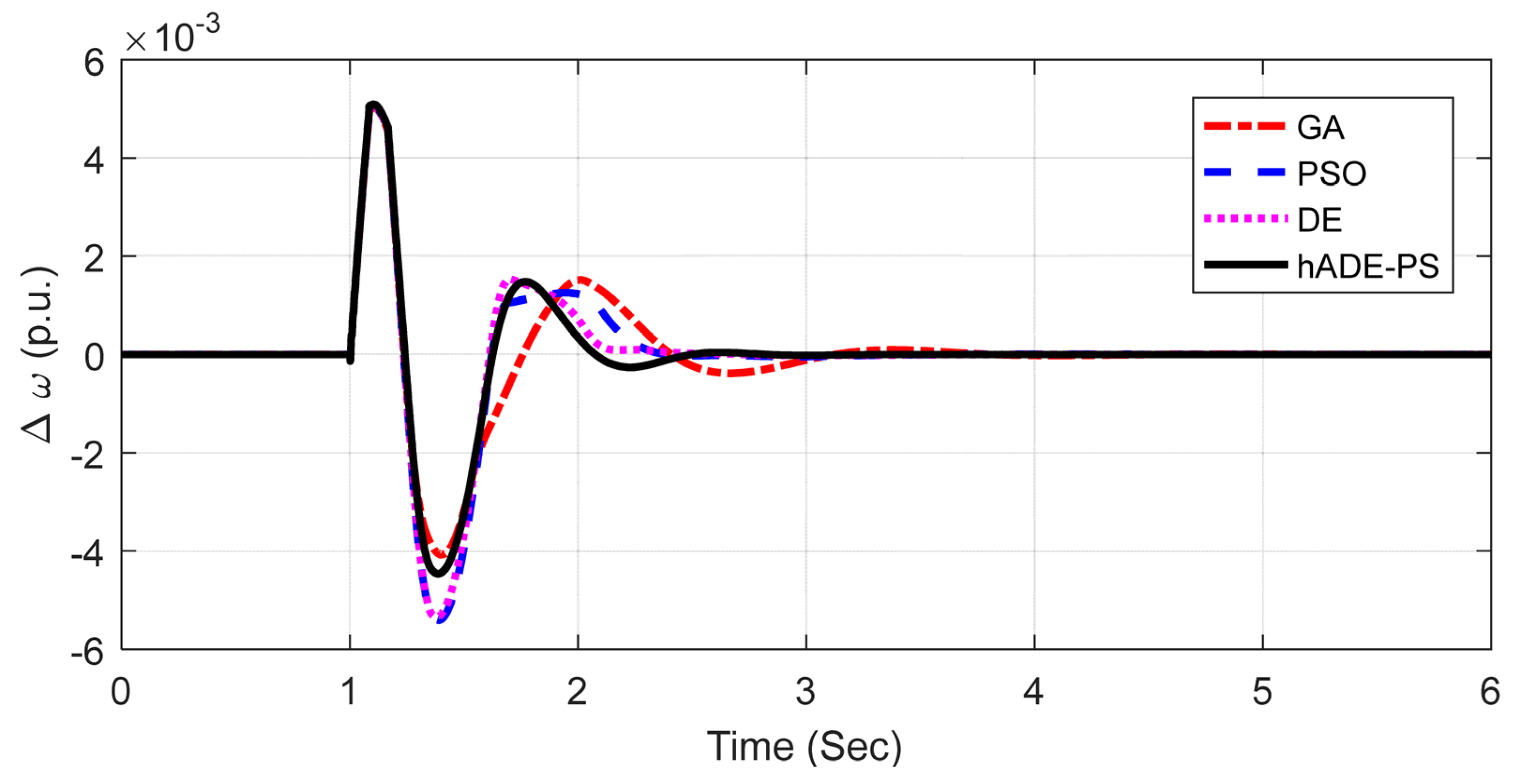
- Technique-wise, the hDE-PS method is compared with GA, PSO, and DE methods, and controller-wise, T2FLL is compared with type-1 fuzzy lead–lag (T1FLL) and widely used lead–lag (LL) controllers.
- iv.
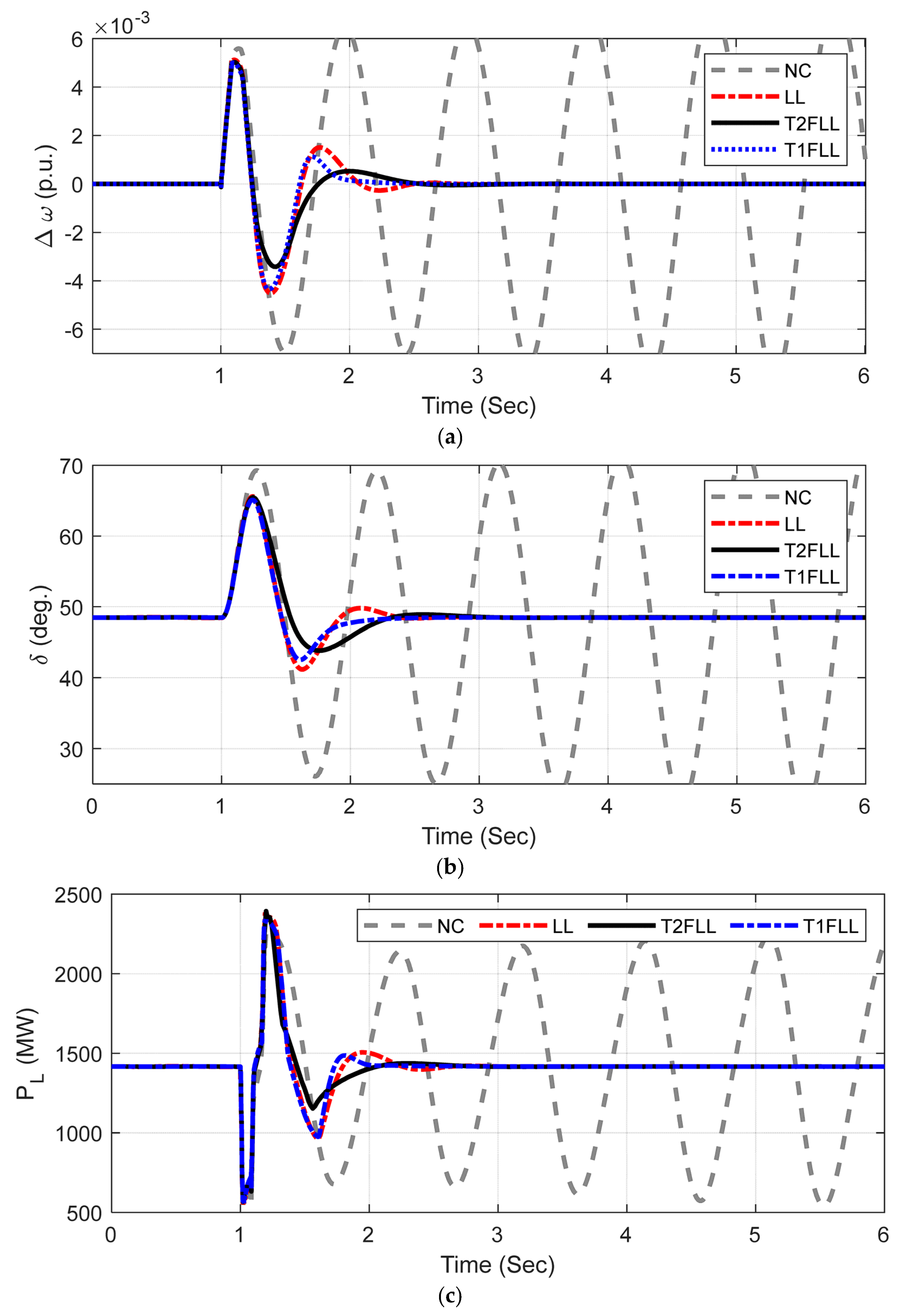
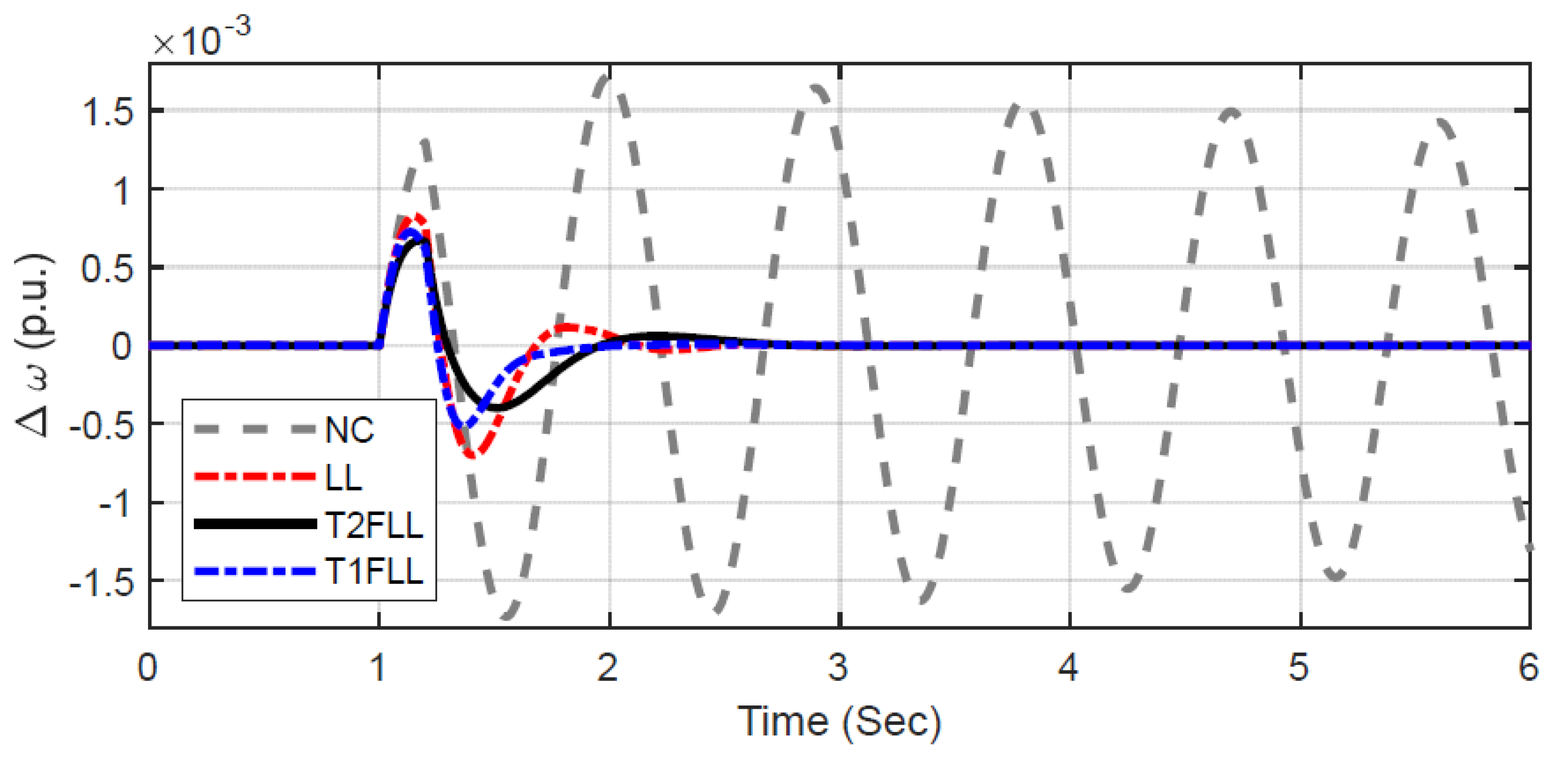
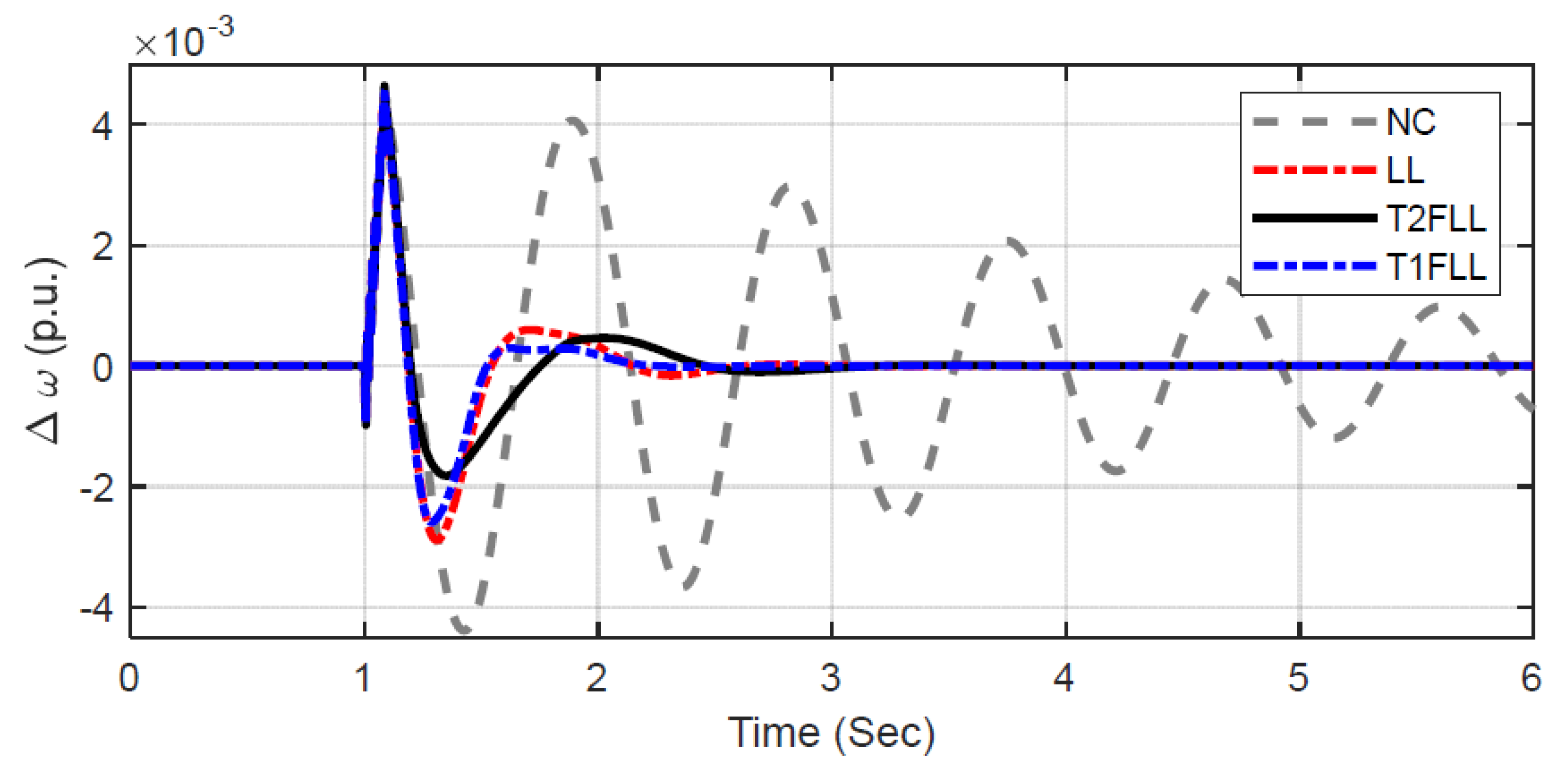
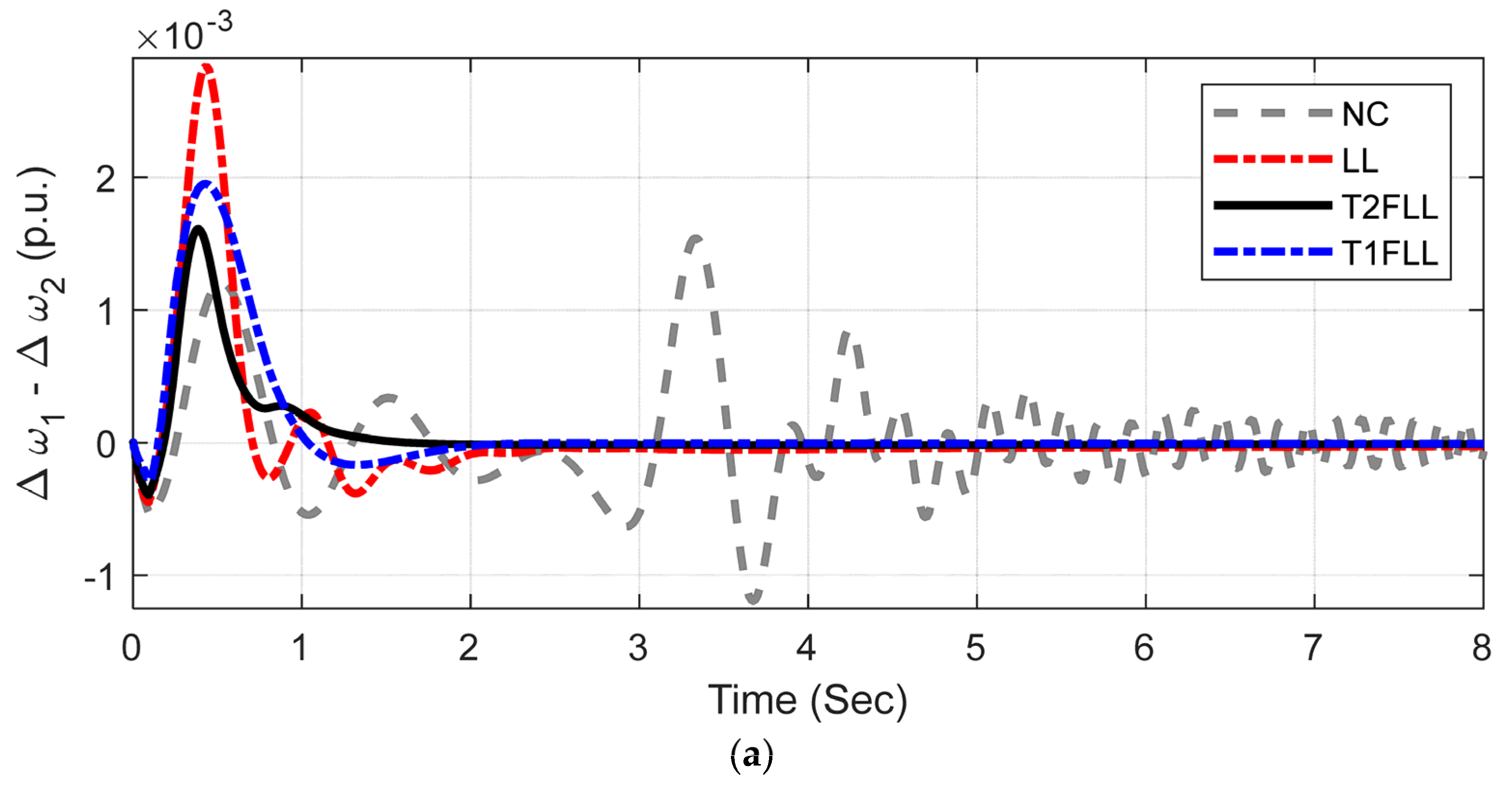
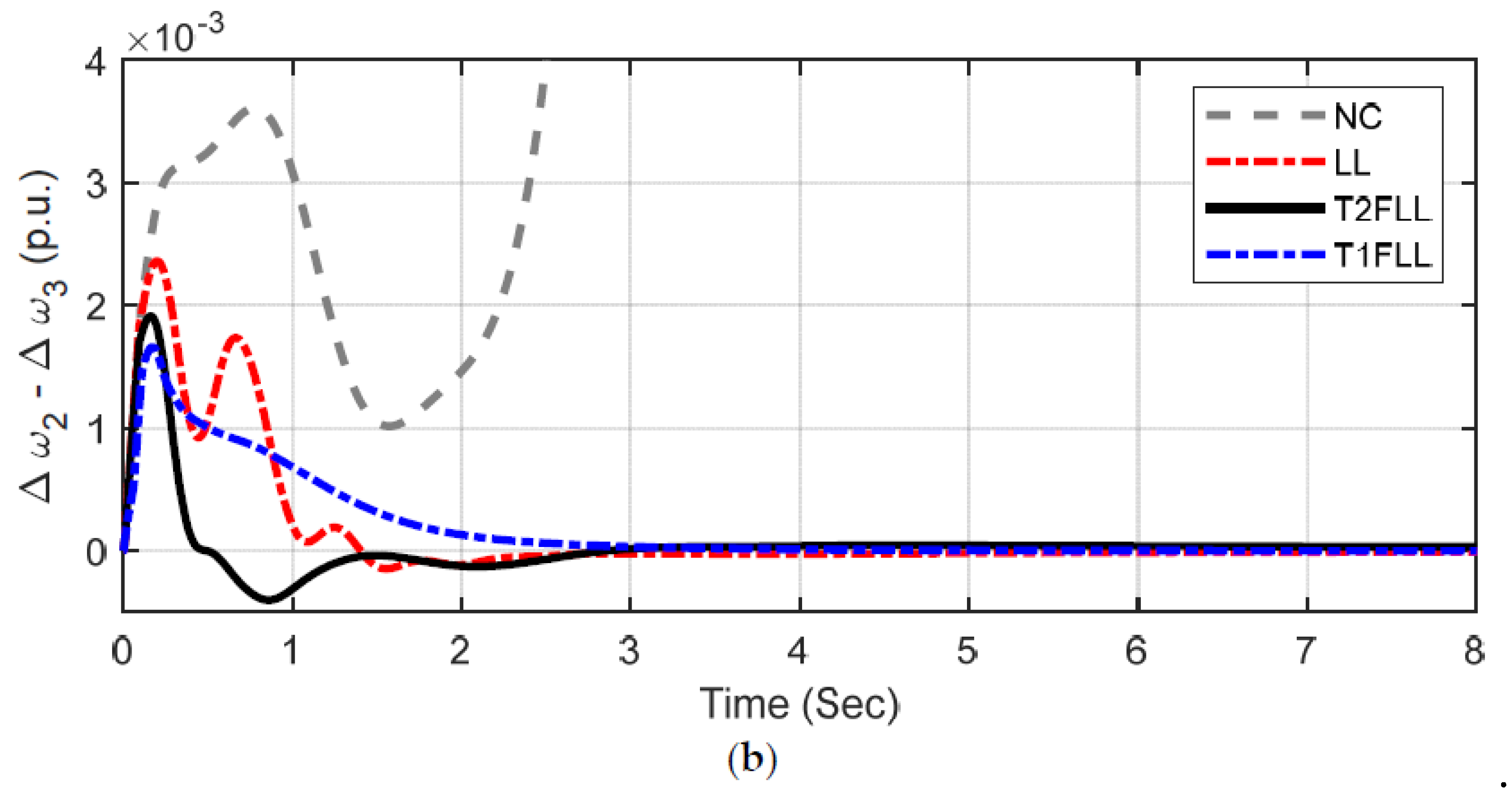
- Various disturbance scenarios and changed loading/fault locations are simulated for both single-machine infinite-bus (SMIB) and MMPS, and it is seen that improved damping is attained with T2FLL related to T1FLL and LL controllers for all scenarios.
2. Systems under Investigation
2.1. The SMIB System
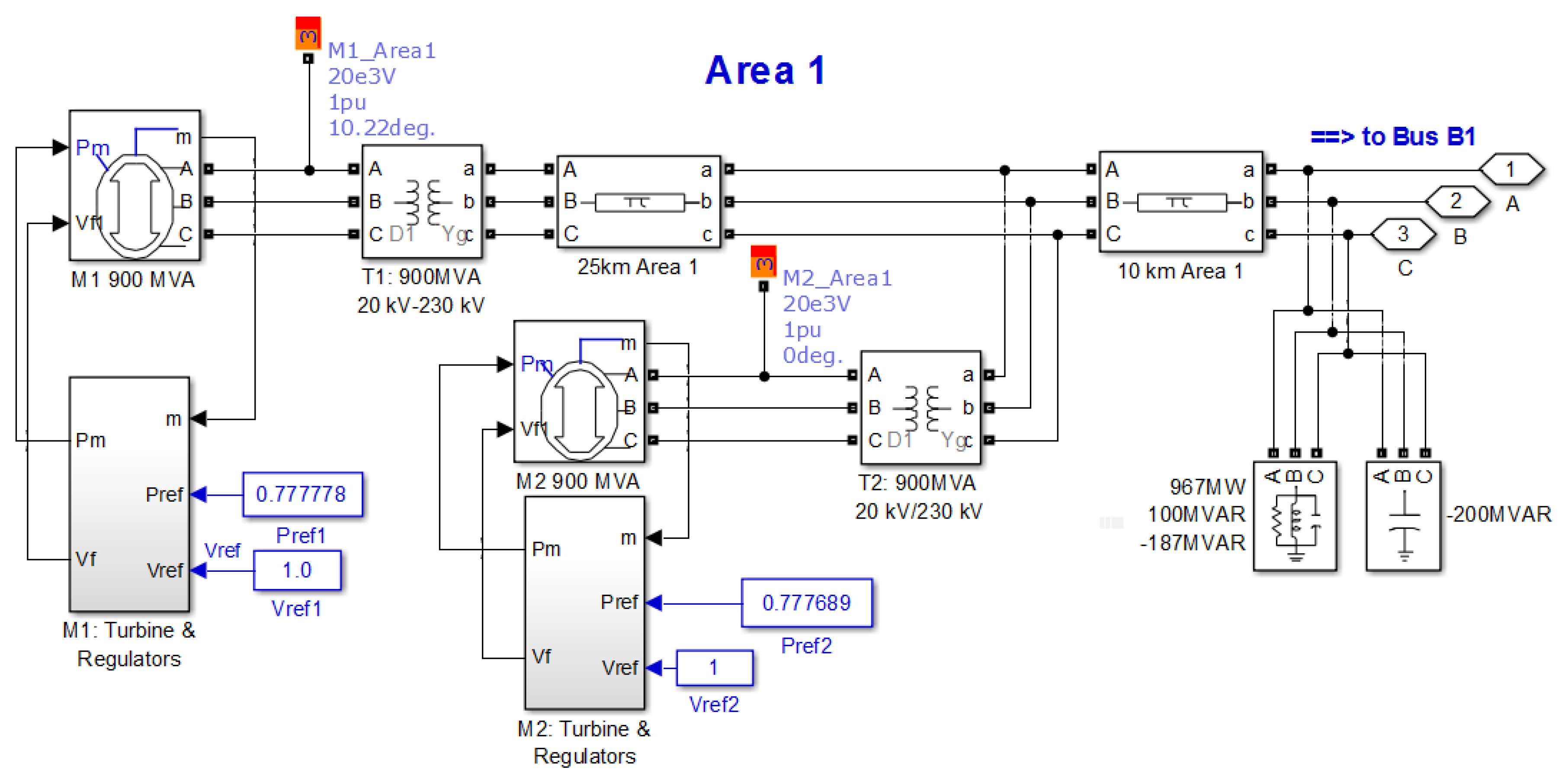
2.2. Kundur’s Test System (Four-Machine Two-Area)
3. The Proposed Approach
3.1. Type-2 Fuzzy Logic Overview
3.2. Structure of T2FLL Controller
3.3. Optimization Problem
4. Overview of Hybrid Adaptive DE and PS Technique
4.1. Mutation
4.2. Crossover
4.3. Selection
5. Outcomes
5.1. SMIB System
5.1.1. Scenario 1: Large Disturbance Condition
5.1.2. Scenario 2: Small Disturbance Condition
5.1.3. Scenario 3: Changed Loading Condition and Fault Location
5.2. Extension to Multi-Machine System (MMPS)
5.2.1. Scenario 1: Three Phase Fault Disturbance Condition
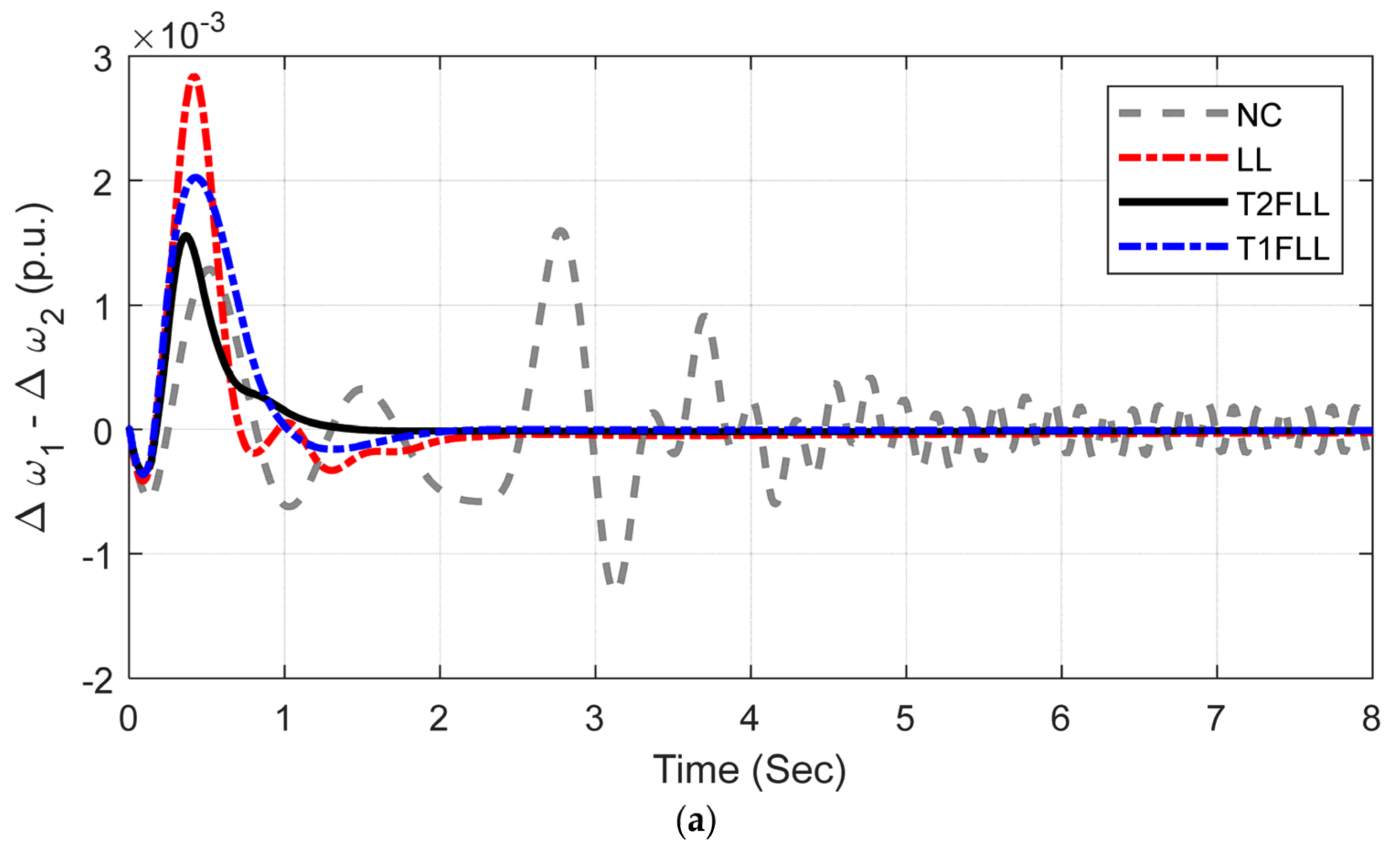
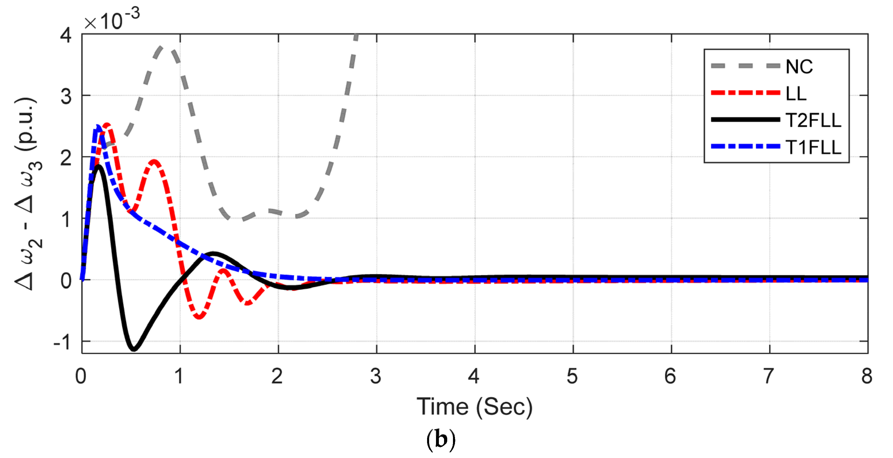
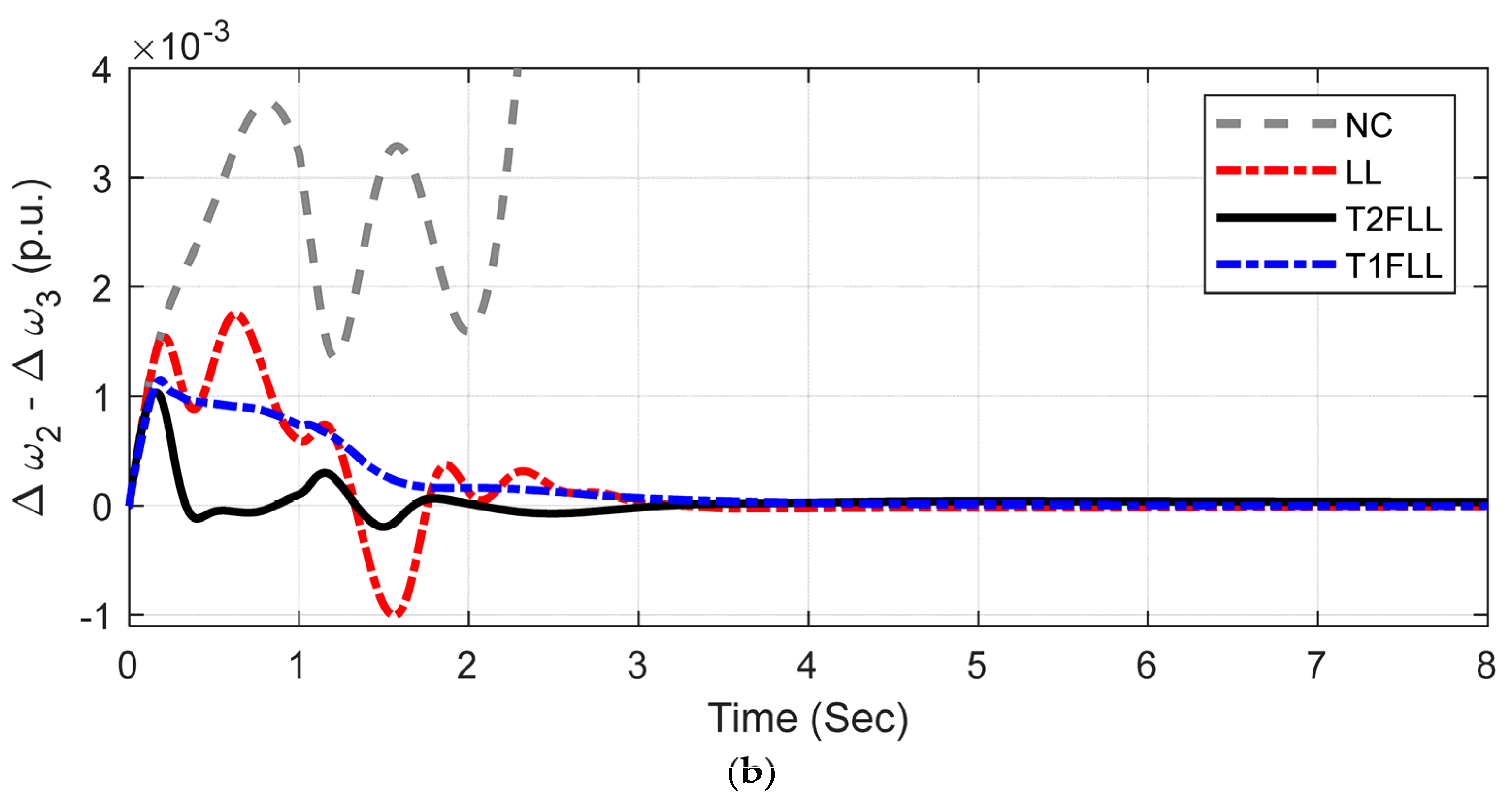
5.2.2. Scenario 2: Line Outage Disturbance Condition
5.2.3. Scenario 3: Small Disturbance Condition
6. Conclusions
Author Contributions
Funding
Institutional Review Board Statement
Informed Consent Statement
Data Availability Statement
Acknowledgments
Conflicts of Interest
Appendix A
| SMIB Parameters |
| Generator: Nominal power (SB),voltage (VB) and frequency (f): 2100 MVA, 13.8 kV, 60 Hz Parameters: Stator resistance (RS): 2.8544 × 10⁻³, Reactances: Xd = 1.305, Xq = 0.474, X’d = 0.296, X’q = 0.243, X’’d = 0.252, X’’q = 0.18, Td = 1.01s, T’d = 0.053s, T’’qo = 0.1s. Inertia constant (H) and pole pairs (p): 3.7 s and 32 Excitation System: Gains (KA) and time constant (TA) of regulator: 200 and 0.001 s Gains (Ke) and time constant (Te) of exciter: 1 and 0 s Gains (Kf) and time constant (Tf) of damping filter: 0.001 and 0.1 s Low-pass filter time constant (TLP): = 0.02 s, Transient gain reduction (Tb, Tc): 0 Regulator output limits (Efmax/Efmin) and gain (Kp): 7/0 and 0 Hydraulic Turbine and Governor: Gains (Ka) and time constant (Ta) of Servo-motor: 3.33 and 0.07 s Limits of Gate opening (Gmax/Gmin and Vgmax/Vgmin): 0.97518/0.01 and 0.01/−0.1 pu/s Permanent droop (Rp): = 0.05, Hydraulic turbine: = 0, = 2.67 sPID regulator (Kp, Ki, Kd, Td): 1.163, 0.105, 0, 0.01 s Transformer: Nominal power (SB) = 2100 MVA, Winding connection: D1/Yg, Primary and secondary voltage (V1/V2): 13.8/500 kV, Resistance (R): 0.002 p.u., Inductances (L1/L2): 0/0.12, Magnetization resistance (Rm) and reactance (Lm): 500 Ω Transmission line: Line length and no. of phases: 300 km, 3-Ph, Resistance per unit length (R1/R0): 0.02546/0.3864 Ω/ km, Inductance per unit length (L1/L0): 0.9337 × 10⁻³ /4.1264 × 10−3 H/km, Capacitance per unit length (C1/C0): 12.74 × 10⁻⁹/7.751 × 10−9 F/ km Load at Bus2: 250 MW (500 kV, 60 Hz, Y-grounded) |
| Kundur’s 4-machine 2-area system |
| Generator: Nominal powers: 900 MVA each, Nominal voltages: 20 kV each, frequency (f): 60 Hz Parameters: Stator resistance (RS): 2.8544 × 10⁻³, Reactances: Xd = 1.8, Xq = 1.7, X’d = 0.3, X’q = 0.55, X’’d = 0.25, X’’q = 0.25, T’do = 8 s, T’’do = 0.03 s, T’qo = 0.4 s, T’’qo = 0.05 s, Stator resistance (RS): 0.0025 Ω Excitation Systems: Each same as SMIB system Steam Turbine and Governor: Regulator Gain (Kp) = 1, Permanent drooop (Rp): 0.05, Dead zone (Dz): 0, Speed relay and servo-motor time constants (Tsr/Tsm): 0.001/0.15 s, Limits of gate opening (Gmax/Gmin and Vgmax/Vgmin): 4.496/0 and 0.01/−0.1 pu/s, time constants of steam turbine (T1, T2, T3, T4): 0, 10, 3.3, 0.5 s, Turbine torque fractions (F1, F2, F3, F4): 0, 0.36, 0.36, 0.28 Transformers: Nominal powers = 900 MVA each, Winding connection: D1/Yg, Primary and secondary voltage (V1/V2): 20/230 kV, Resistance (R): 1 × 10⁻⁶, Inductances (L1/L2): 0/0.15, Magnetization resistance (Rm) and reactance (Lm): 500 Ω Transmission lines: Distributed parameter line (110 km line sections) and PI section line (10 km and 25 km line sections) Line length and n0. of phases: 300 km, 3-Ph, Resistance per unit length (R1/R0): 0.0529/1.61 Ω/km, Inductance per unit length (L1/L0): 0.0014/0.0061 H/km, Capacitance per unit length (C1/C0): 8.7749 × 10⁻⁹/5.2489 × 10−9 F/km Loads: Area-1: Active power: 967 MW, Inductive reactive power: 100 MVAR, Capacitive reactive power: 387 MVAR Area-2: Active power: 1767 MW, Inductive reactive power: 100 MVAR, Capacitive reactive power: 537 MVAR |
| SSSC Data |
| Converter rating: = 100 MVA, Nominal voltage: 500 kV, Frequency (f): 60 Hz, Maximum rate of change in reference voltage = 3 pu/s, Converter impedances (R/L): 0.00533/0.16, DC link voltage: 40 kV, DC link equivalent capacitance: 375 × 10−6 F, Injected Voltage regulator gains (KP /KI): 0.00375/0.1875, DC Voltage regulator gains (KP/KI ): 0.1 × 10⁻³/20 × 10−3, Limits of injected voltage: ± 0.2 |
References
- Yu, Y.N. Electric Power System Dynamics; Academic Press: New York, NY, USA, 1983. [Google Scholar]
- Sauer, P.W.; Pai, M.A. Power System Dynamics and Stability; Prentice-Hall: Englewood Cliffs, NJ, USA, 1998. [Google Scholar]
- Gyugyi, L.; Schauder, C.D.; Sen, K.K. Static synchronous series compensator: A solid-state approach to the series compensation of transmission lines. IEEE Trans. Power Deliv. 1997, 12, 406–417. [Google Scholar] [CrossRef]
- Panda, S.; Ardil, C. Robust coordinated design of multiple power system stabilizers using particle swarm optimization technique. Int. J. Electr. Syst. Sci. Eng. 2008, 1, 41–48. [Google Scholar]
- Panda, S.; Padhy, N.P. Robust power system stabilizer design using particle swarm optimization technique. Int. J. Electr. Syst. Sci. Eng. 2008, 1, 2260–2267. [Google Scholar]
- Abdel-Magid, Y.L.; Abido, M.A.; Al-Baiyat, S.; Mantawy, A.H. Simultaneous stabilization of multi-machine stabilizers via genetic algorithm. IEEE Trans. Power Syst. 1999, 14, 1428–1439. [Google Scholar] [CrossRef]
- Sebaa, K.; Boudour, M. Optimal locations and tuning of robust power system stabilizer using genetic algorithms. Int. J. Electr. Power Syst. Res. 2009, 79, 406–416. [Google Scholar] [CrossRef]
- Paul, S.; Roy, P.K. Oppositional cuckoo optimization algorithm for optimal tuning of power system stabilizers. In Proceedings of the Michael Faraday IET International Summit, Kolkata, India, 12–13 September 2015; pp. 176–181. [Google Scholar]
- Abido, M.A. Robust design of multi-machine power system stabilizers using simulated annealing. IEEE Trans Energy Convers. 2000, 15, 297–304. [Google Scholar] [CrossRef]
- Abdel-Magid, Y.L.; Abido, M.A.; Mantawy, A.H. Robust tuning of power system stabilizers in multi-machine power systems. IEEE Trans Power Syst. 2000, 15, 735–740. [Google Scholar] [CrossRef]
- Mishra, S.; Tripathy, M.; Nanda, J. Multi-machine power system stabilizer design by rule based bacteria foraging. Int. J. Electr. Power Syst. Res. 2007, 77, 1595–1607. [Google Scholar] [CrossRef]
- Jolfaei, M.G.; Sharaf, A.M.; Shariatmadar, S.M.; Poudeh, M.B. A hybrid PSS–SSSC GA-stabilization scheme for damping power system small signal oscillations. Electr. Power Energy Syst. 2016, 75, 337–344. [Google Scholar] [CrossRef]
- Falehi, A.D.; Rostami, M.; Doroudi, A.; Ashrafian, A. Optimization and coordination of SVC-based supplementary controllers and PSSs to improve power system stability using a genetic algorithm. Turk. J. Elec. Eng. Comp. Sci. 2012, 20, 639–654. [Google Scholar]
- Khadanga, R.K.; Satapathy, J.K. Time delay approach for PSS and SSSC based coordinated controller design using hybrid PSO–GSA algorithm. Int. J. Electr. Power Energy Syst. 2015, 71, 262–273. [Google Scholar] [CrossRef]
- Tripathy, M.; Mishra, S. Coordinated tuning of PSS and TCSC to improve hopf bifurcation margin in multi-machine power system by a modified bacteria foraging algorithm. Int. J. Electr. Power Energy Syst. 2015, 66, 97–109. [Google Scholar] [CrossRef]
- Ali, E.S.; Abd-Elazim, S.M. Coordinated design of PSSs and TCSC via bacterial swarm optimization algorithm in a multi-machine power system. Int. J. Electr. Power Energy Syst. 2012, 36, 84–92. [Google Scholar] [CrossRef]
- Shayeghi, H.; Safari, A.; Shayanfar, H.A. PSS and TCSC damping controller coordinated design using PSO in multi-machine power system. Energy Convers Manag. 2010, 51, 2930–2937. [Google Scholar] [CrossRef]
- Dadfar, S.; Wakil, K.; Khaksar, M.; Rezvani, A.; Miveh, M.R.; Gandomkar, M. Enhanced control strategies for a hybrid battery/photovoltaic system using FGS-PID in grid-connected mode. Int. J. Hydrog. Energy 2019, 44, 14642–14660. [Google Scholar] [CrossRef]
- Khaksar, M.; Rezvani, A.; Moradi, M.H. Simulation of novel hybrid method to improve dynamic responses with PSS and UPFC by fuzzy logic controller. Neural Comput. Appl. 2018, 29, 837–853. [Google Scholar] [CrossRef]
- Rezvani, A.; Esmaeily, A.; Etaati, H.; Mohammadinodoushan, M. Intelligent hybrid power generation system using new hybrid fuzzy-neural for photovoltaic system and RBFNSM for wind turbine in the grid connected mode. Front. Energy 2019, 13, 131–148. [Google Scholar] [CrossRef]
- Ray, P.K.; Paital, S.R.; Mohanty, A.; Eddy, F.Y.S.; Krishnan, A.; Gooi, H.B.; Amaratunga, G.A.J. A hybrid firefly-swarm optimized fractional order interval type-2 fuzzy PID-PSS for transient stability improvement. IEEE Trans. Ind. Appl. 2019, 55, 6486–6498. [Google Scholar] [CrossRef]
- Elazim, S.M.A.; Ali, E.S. Optimal power system stabilizers design via cuckoo search algorithm. Int. J. Electr. Power Energy Syst. 2016, 75, 99–107. [Google Scholar] [CrossRef]
- Ali, E.S. Optimization of power system stabilizers using BAT search algorithm. Int. J. Electr. Power Energy Syst. 2014, 61, 683–690. [Google Scholar] [CrossRef]
- Elazim, S.M.A.; Ali, E.S. Optimal location of STATCOM in multimachine power system for increasing loadability by cuckoo search algorithm. Int. J. Electr. Power Energy Syst. 2016, 80, 240–251. [Google Scholar] [CrossRef]
- Abdelaziz, A.Y.; Ali, E.S. Static VAR compensator damping controller design based on flower pollination algorithm for a multi-machine power system. Electr. Power Compon. Syst. 2015, 43, 1268–1277. [Google Scholar] [CrossRef]
- Abd Elazim, S.M.; Ali, E.S. Optimal SSSC design for damping power systems oscillations via gravitational search algorithm. Int. J. Electr. Power Energy Syst. 2016, 82, 161–168. [Google Scholar] [CrossRef]
- Elazim, S.M.A.; Ali, E.S. Coordinated design of PSSs and SVC via bacteria foraging optimization algorithm in a multi-machine power system. Int. J. Electr. Power Energy Syst. 2012, 41, 44–53. [Google Scholar] [CrossRef]
- Stron, R.; Price, K. Differential evolution—A simple and efficient adaptive scheme for global optimization over continuous spaces. J. Glob. Optim. 1997, 11, 341–359. [Google Scholar] [CrossRef]
- Sahu, R.K.; Gorripotu, T.S.; Panda, S. A hybrid DE–PS algorithm for load frequency control under deregulated power system with UPFC and RFB. Ain Shams Eng. J. 2015, 6, 893–911. [Google Scholar] [CrossRef]
- Mohanty, P.; Sahu, R.K.; Panda, S. A novel hybrid many optimizing liaisons gravitational search algorithm approach for AGC of power systems. Autom. J. Control. Meas. Electron. Comput. Commun. 2020, 61, 158–178. [Google Scholar] [CrossRef]
- Khadanga, R.K.; Kumar, A.; Panda, S. A hybrid shuffled frog-leaping and pattern search algorithm for load frequency controller design of a two-area system composing of PV grid and thermal generator. Int. J. Numer. Modeling 2020, 33, e2694. [Google Scholar] [CrossRef]
- Rout, B.D.; Pati, B.B.; Panda, S. A hybrid modified differential evolution-pattern search approach for SSSC based damping controller design under communication constraints. Int. J. Syst. Assur. Eng. Manag. 2018, 9, 962–971. [Google Scholar] [CrossRef]
- Zhang, J.; Sanderson, A.C. JADE: Adaptive differential evolution with optional external archive. IEEE Trans Evol. Comput. 2009, 13, 945–958. [Google Scholar] [CrossRef]
- Wang, Y.; Cai, Z.; Zhang, Q. Differential evolution with composite trial vector generation strategies and control parameters. IEEE Trans Evol. Comput. 2011, 15, 55–66. [Google Scholar] [CrossRef]
- Tanabe, R.; Fukunaga, A. Success-history based parameter adaptation for differential evolution. In Proceedings of the IEEE CEC, Cancun, Mexico, 20–23 June 2013; pp. 71–78. [Google Scholar]
- Mohanty, P.; Sahu, R.K.; Sahoo, D.K.; Panda, S. Adaptive differential evolution and pattern search tuned fractional order fuzzy PID for frequency control of power systems. Int. J. Model. Simul. 2022, 42, 240–254. [Google Scholar] [CrossRef]
- SimPowerSystems 4.3 User’s Guide. Available online: http://www.mathworks.com/products/simpower/ (accessed on 3 March 2022).
- Kundur, P. Power System Stability and Control; McGraw-Hill: Irvine, CA, USA, 1994; p. 813, Example 12.6. [Google Scholar]
- Chintu, J.M.; Sahu, R.K.; Panda, S. Adaptive differential evolution tuned hybrid fuzzy PD-PI controller for automatic generation control of power systems. Int. J. Ambient. Energy 2019, 17, 1–6. [Google Scholar] [CrossRef]
- Liu, J.; Lampinen, J. A fuzzy adaptive differential evolution algorithm. Soft Comput. 2005, 9, 448–462. [Google Scholar] [CrossRef]
- Gamperle, R.; Muller, S.D.; Koumoutsakos, P. A parameter study for differential evolution. Adv. Intell. Syst. Fuzzy Syst. Evol. Comput. 2002, 10, 293–298. [Google Scholar]
- Ali, M.M.; Torn, A. Population set-based global optimization algorithms: Some modifications and numerical studies. Comput. Oper. Res. 2004, 31, 1703–1725. [Google Scholar] [CrossRef]
- Biswas, P.P.; Suganthan, P.N.; Wu, G.; Amaratunga, G.A. Parameter estimation of solar cells using datasheet information with the application of an adaptive differential evolution algorithm. Renew. Energy 2019, 132, 425–438. [Google Scholar] [CrossRef]
- Panda, S.; Padhy, N.P. Comparison of Particle Swarm Optimization and Genetic Algorithm for FACTS-based Controller Design. Appl. Soft Comput. 2008, 8, 1418–1427. [Google Scholar] [CrossRef]
- Mohanty, B.; Panda, S.; Hota, P.K. Controller parameters tuning of differential evolution algorithm and its application to load frequency control of multi-source power system. Int. J. Electr. Power Energy Syst. 2014, 54, 77–85. [Google Scholar] [CrossRef]
- Swain, S.C.; Panda, S.; Mahapatra, S. A multi-criteria optimization technique for SSSC based power oscillation damping controller design. Ain Shams Eng. J. 2016, 7, 553–565. [Google Scholar] [CrossRef]
- Panda, S.; Yegireddy, N. Multi-input single output SSSC based damping controller design by a hybrid improved differential evolution-pattern search approach. ISA Trans. 2015, 58, 173–185. [Google Scholar] [CrossRef] [PubMed]
- Panda, S.; Kiran, S.H.; Dash, S.S.; Subramani, C. A PD-type multi input single output SSSC damping controller design employing hybrid improved differential evolution-pattern search approach. Appl. Soft Comput. 2015, 32, 532–543. [Google Scholar] [CrossRef]





| ė | EXN | LN | ZER | LP | EXP | |
|---|---|---|---|---|---|---|
| e | ||||||
| EXN | EXN | EXN | LN | LN | ZER | |
| LN | EXN | LN | EXN | ZER | LP | |
| ZER | LN | LN | ZER | LP | LP | |
| LP | LN | ZER | LP | LP | EXP | |
| EXP | ZER | LP | LP | EXP | EXP | |
| Technique | Controller | Ki | T1i | T2i | T3i | T4i | J Value × 10−3 |
|---|---|---|---|---|---|---|---|
| GA | SSSC | 74.0740 | 0.4286 | 0.0511 | 0.4523 | 1.1098 | 44.3216 |
| PSS | 19.8294 | 0.1415 | 0.0011 | 0.0630 | 1.2736 | ||
| PSO | SSSC | 38.5588 | 1.0653 | 0.3218 | 0.6751 | 0.7496 | 40.9781 |
| PSS | 24.2563 | 1.5546 | 1.4223 | 0.0134 | 0.4930 | ||
| DE | SSSC | 50.1218 | 0.8175 | 1.1379 | 1.4961 | 0.4326 | 37.7718 |
| PSS | 16.0860 | 0.1553 | 0.7317 | 1.7974 | 1.7974 | ||
| hADE-PS | SSSC | 71.5265 | 1.2006 | 1.3051 | 0.0011 | 0.0012 | 33.7926 |
| PSS | 18.2475 | 0.0011 | 0.5204 | 0.0011 | 0.4981 |
| Controller | KSF1 | KSF2 | Ki | T1i | T2i | T3i | T4i | J Value × 10−3 |
|---|---|---|---|---|---|---|---|---|
| T2FLL controller | ||||||||
| SSSC | 0.0105 | 0.1824 | 79.5279 | 1.9974 | 1.5774 | 1.0292 | 0.4604 | 28.6961 |
| PSS | 0.0104 | 0.7241 | 49.9350 | 0.0622 | 1.6995 | 0.0012 | 1.9974 | |
| T1FLL controller | ||||||||
| SSSC | 1.9093 | 1.4684 | 14.2391 | 0.0154 | 0.4538 | 1.9974 | 0.9935 | 31.9342 |
| PSS | 0.3209 | 1.2285 | 30.5106 | 0.2421 | 1.7827 | 0.4172 | 1.9974 | |
| Scenario/Controller | ISE (×10−6) | ITAE (×10−2) | ITSE (×10−3) | IAE (×10−6) | Overshoots in Δω (×10−3) | Undershoots in Δω (×10−3) | |
|---|---|---|---|---|---|---|---|
| Scenario 1 | NC | 256.6942 | 244.0563 | 43.0972 | 1493.7607 | 7.786 | −8.6124 |
| LL | 7.7379 | 3.3792 | 2.3878 | 10.1409 | 5.0881 | −4.4641 | |
| T1FLL | 6.8863 | 3.1934 | 2.0871 | 8.8434 | 4.998 | −4.3516 | |
| T2FLL | 5.8701 | 2.86961 | 2.0413 | 7.4721 | 5.0363 | −3.3831 | |
| Scenario 2 | NC | 9.3642 | 42.5216 | 8.1817 | 45.9841 | 1.7148 | 1.7312 |
| LL | 0.1951 | 0.4901 | 0.3586 | 0.2514 | 0.8321 | −0.7049 | |
| T1FLL | 0.1668 | 0.4862 | 0.3398 | 0.2163 | 0.7148 | −0.5189 | |
| T2FLL | 0.1162 | 0.4618 | 0.3142 | 0.1528 | 0.6732 | −0.3972 | |
| Scenario 3 | NC | 19.6749 | 30.5829 | 9.0338 | 48.6916 | 4.6224 | −4.3954 |
| LL | 2.6978 | 1.825 | 1.3121 | 3.3519 | 4.5324 | −2.8929 | |
| T1FLL | 2.4873 | 1.8011 | 1.2967 | 3.0572 | 4.5324 | −2.2581 | |
| T2FLL | 2.2042 | 1.8169 | 1.2816 | 2.73604 | 4.5324 | −1.8272 | |
| Controller | Ki | T1i | T2i | T3i | T4i |
|---|---|---|---|---|---|
| SSSC | 92.8460 | 0.0885 | 0.0308 | 4.5494 | 7.4982 |
| PSS1 | 46.8908 | 0.0430 | 0.0182 | 2.7794 | 8.8044 |
| PSS2 | 48.0950 | 0.0114 | 0.0155 | 3.9735 | 3.5212 |
| PSS3 | 45.8967 | 0.0712 | 0.0128 | 3.7749 | 3.2167 |
| PSS4 | 27.6544 | 0.0974 | 0.0319 | 3.8884 | 3.2087 |
| Controller | KSF1 | KSF2 | Ki | T1i | T2i | T3i | T4i |
|---|---|---|---|---|---|---|---|
| T2FLL controller | |||||||
| SSSC | 0.0102 | 0.0148 | 41.0552 | 0.0990 | 0.0064 | 1.5070 | 2.9408 |
| PSS1 | 0.7591 | 0.0126 | 24.6432 | 0.0193 | 0.0066 | 2.4321 | 2.3374 |
| PSS2 | 1.9797 | 0.0468 | 16.5071 | 0.0394 | 0.0104 | 1.9728 | 1.5423 |
| PSS3 | 0.0765 | 0.0284 | 37.0997 | 0.0992 | 0.0059 | 2.4474 | 3.0812 |
| PSS4 | 1.2245 | 0.2568 | 11.0542 | 0.0155 | 0.0051 | 1.7857 | 0.9991 |
| T1FLL controller | |||||||
| SSSC | 0.2323 | 0.5164 | 2.7141 | 0.0103 | 0.0101 | 4.9493 | 2.0462 |
| PSS1 | 1.0206 | 0.0871 | 11.7451 | 0.0194 | 0.0066 | 3.2127 | 3.8817 |
| PSS2 | 1.5428 | 0.4353 | 40.6019 | 0.0415 | 0.0383 | 2.3425 | 3.8154 |
| PSS3 | 0.9495 | 0.0100 | 49.4935 | 0.0121 | 0.0060 | 4.2398 | 4.4935 |
| PSS4 | 1.4140 | 0.0492 | 35.8082 | 0.0115 | 0.0239 | 2.4098 | 3.6268 |
| Scenario/Controller | Scenario 1 (×10−3) | Scenario 2 (×10−3) | Scenario 3 (×10−3) |
|---|---|---|---|
| NC | 20,806.0798 | 21,201.1951 | 21,040.6094 |
| LL | 14.5224 | 12.8586 | 17.4648 |
| T1FLL | 12.6361 | 11.8245 | 13.8912 |
| T2FLL | 9.9952 | 10.6961 | 10.5976 |
Publisher’s Note: MDPI stays neutral with regard to jurisdictional claims in published maps and institutional affiliations. |
© 2022 by the authors. Licensee MDPI, Basel, Switzerland. This article is an open access article distributed under the terms and conditions of the Creative Commons Attribution (CC BY) license (https://creativecommons.org/licenses/by/4.0/).
Share and Cite
Khampariya, P.; Panda, S.; Alharbi, H.; Abdelaziz, A.Y.; Ghoneim, S.S.M. Coordinated Design of Type-2 Fuzzy Lead–Lag-Structured SSSCs and PSSs for Power System Stability Improvement. Sustainability 2022, 14, 6656. https://doi.org/10.3390/su14116656
Khampariya P, Panda S, Alharbi H, Abdelaziz AY, Ghoneim SSM. Coordinated Design of Type-2 Fuzzy Lead–Lag-Structured SSSCs and PSSs for Power System Stability Improvement. Sustainability. 2022; 14(11):6656. https://doi.org/10.3390/su14116656
Chicago/Turabian StyleKhampariya, Prabodh, Sidhartha Panda, Hisham Alharbi, Almoataz Y. Abdelaziz, and Sherif S. M. Ghoneim. 2022. "Coordinated Design of Type-2 Fuzzy Lead–Lag-Structured SSSCs and PSSs for Power System Stability Improvement" Sustainability 14, no. 11: 6656. https://doi.org/10.3390/su14116656
APA StyleKhampariya, P., Panda, S., Alharbi, H., Abdelaziz, A. Y., & Ghoneim, S. S. M. (2022). Coordinated Design of Type-2 Fuzzy Lead–Lag-Structured SSSCs and PSSs for Power System Stability Improvement. Sustainability, 14(11), 6656. https://doi.org/10.3390/su14116656


