Article

Determination and Comparative Analysis of Critical Velocity for Five Objects of Railway Vehicle Class

by
Krzysztof Zboinski
and
Milena Golofit-Stawinska
*
Faculty of Transport, Warsaw University of Technology, Koszykowa 75, 00-662 Warsaw, Poland
*
Author to whom correspondence should be addressed.
Sustainability 2022, 14(11), 6649; https://doi.org/10.3390/su14116649
Submission received: 29 March 2022 / Revised: 20 April 2022 / Accepted: 25 April 2022 / Published: 29 May 2022
(This article belongs to the Special Issue Sustainable Operation and Maintenance of Railway Systems)

Abstract

:
The purpose of this article is to determine the critical velocities for five railway vehicle objects and to find possible generalizations of these results. It is done in the context of increasing the safety of travel on modern railways. The article discusses four methods of determining these velocities, and then the results obtained, mainly using one of the methods, are presented in tabular and graphical form. The chosen method is supplemented with the second one when higher accuracy or certainty is necessary. Finally, the results are discussed and the similarities and differences between them for different groups of railway vehicle class objects are shown.

1. Introduction

The authors of this article focus their general studies on the lateral dynamics (motion) of rail vehicles that move along the transition curve (TC) section. A need exists in these general studies to determine the critical velocity(ies) of the objects representing railway vehicles. The purpose of the studies discussed in the present article and the article itself is meant to determine the critical velocities (vn) for five railway vehicle objects: three bogies (25TN bogie of a freight car, a bogie with averaged parameters, and a bogie of the MKIII passenger car) and two 2-axle freight cars (the car with averaged parameters and the hsfv1 car). Moreover, the results of a 4-axle passenger car MKIII from [1] are considered as well. Note in this context that very often researchers focus on a single object and try to learn about or find a solution for it. The present paper is different, the authors are not attached to and restricted by such a single object. They consider six objects of different classes that cover a wide range of real railway vehicles. Then they look for similarities and differences between these objects rather than for any restricted solution for a particular object. The authors are on their way to hopefully finding some generalizations or showing honestly that they do not exist or at the current stage cannot be formulated. Papers with such an approach are rather exceptional in the field studied. The paper’s purpose and scope just formulated are also different from the authors’ earlier papers. For example, in [1], just two objects were of interest and just one was identical to discussed here. In [2], the objects’ non-linear behaviour was of interest. The critical velocity was neither of the main interest nor compared for different objects. Determining the critical velocity in the context of the dynamics of rail vehicles in TCs and their vicinity, especially at velocities higher than the critical velocity, is important for modern railways. Everyone expects that rail vehicles will travel at higher and higher velocities. Railway vehicles as a rule are built so that their range of exploitation velocities is below the critical velocity. On the other hand, exceeding critical velocity does not at once means some unacceptable or dangerous state. It is usually just a less favourable state than motion below the critical velocity. However, the higher the velocity above the critical one, the higher amplitudes of vehicle hunting motion occur. At some stage, these are so high that a real danger of vehicle derailment can appear. These basic features of critical velocity connected with motion below and above the critical value of velocity explain its importance both for vehicle construction, modernization, and exploitation as well as safety of motion.
Despite the simplicity of the above-described features, some difficulties appear when it comes to their practical utilization. These are connected with the accuracy of critical and derailment velocities determination, which arises from imperfections of railway vehicle models. It is obvious as models are always some approximation of reality. The methods of critical velocity determination can be divided into two groups. The first are analytical methods, while the second are simulation methods. The analytical methods have some serious limitations. Namely, they are efficient for low dimensions of the models. In practice, it is 1 or 2 degrees of freedom (DOFs) only. They are valid in the small vicinity of the system equilibrium position. Moreover, they often make use of linear models, which makes these models even less credible. The main advantage of the simulation methods is the possibility of their use for high dimension systems (of many DOFs), which actually correspond to railway vehicle models. Many non-linearities of the system can be taken into account as well. On the other hand, these methods are still based on some mathematical models converted next into numerical (simulation) models with their limitations concerning accuracy. Concluding, the limited accuracy of the critical velocity determination with limited ability to project derailment processes with the simulation methods makes results from both groups of methods useful in a qualitative but not quantitative sense. This means that qualitative comparisons between particular vehicle variants or between different vehicles are sensible and credible while the quantitative determination of critical or derailment velocity is burdened with too high a possible error.
High critical velocities in straight track (ST), resulting in high exploitation velocities, and good driving performance in a circular curve (CC), resulting in reduced wheel–rail wear and increased safety, are the features that are difficult to reconcile. It is the reason why the modern approach to rail vehicles’ stability refers to looking for stable periodic solutions (hunting motion) both in ST and CCs. Correspondingly, the issue of critical velocity determination concerns nowadays ST and CCs, taking account of different the curves’ radii R. It should be noted that periodic stable solutions may appear only in the case of these two track sections, i.e., ST and CC, as they are sections of the route with fixed motion conditions. Such fixed conditions cannot be expected in the case of TC, where the radius of curvature and superelevation (considering the route in general as 3-dimensional) change continuously along the entire TC length. Therefore, in the case of the TC one not only cannot expect, but it is also of no sense to look for, stable periodic (limit cycles) and stable stationary solutions, which is the essence of the analysis of the rail vehicles stability. Going further, also the critical velocity in the TC cannot be calculated. Nevertheless, the transition nature of the phenomena in the TC and studying them allows for the recognition of non-linear dynamic features of rail vehicle class systems, which are difficult to detect in case of motion in ST and CC. One should remember, however, that any solution, even non-stationary or non-periodic, can be checked for stability. Thus, also for solutions in the TC, it is possible to introduce a series of small disturbances (e.g., non-zero initial conditions) into the system and check whether the newly obtained solutions are close enough to the solution adopted as a model solution. If yes, the solution in the TC will be stable.

2. The Basics of the Motion Stability Analysis

The connection of the rail vehicle stability issue with the studies of dynamics in TCs was explained in the previous section. This issue is treated by the authors in a manner called the bifurcation approach and, as most often in the literature, this applies to the so-called non-linear lateral stability. The term non-linear means non-linear models of rail vehicles, but also the so-called non-linear methods of stability testing. The term “lateral” means the interest in lateral displacements and rotation angles around the vertical axis (yaw angles) of vehicle elements. In practice, it is limited to the leading wheelsets most often. The subject of the stability study of non-linear systems is the search for the critical value of the bifurcation parameter as well as the nature and value of solutions for the entire range of its changes. In the case of rail vehicles, the major bifurcation parameter is velocity, while its critical value corresponds to the non-linear critical velocity vn.
As discussed, among others, in [3,4,5,6], the theory of self-excited vibrations [7] can be used to describe the hunting motion of a wheelset as well.
In stability theory, the bifurcation plots present non-linear features (the behaviour) of an object (system) represented by its non-linear model. In particular, the bifurcation of solutions is presented. On these plots, the values of the model coordinate directly or their maximum values (in the case of vibrations) subject to observation are presented in the function of the bifurcation parameter. An example of the most typical bifurcation graph for rail vehicles in CC, assuming the subcritical features [2,8,9] of the system, is shown in Figure 1. Example figures for ST can be found in [8,9]. It must be highlighted here that Figure 1 is not the general case. It is one of the simplest possible cases. On the other hand, quite many real vehicles (their models) possess features as shown in Figure 1. Example solutions of a character different than in Figure 1 can be found in [10,11,12].
Figure 1 includes two types of critical velocities which are denoted with vc and vn and called the linear and non-linear critical velocity, respectively. They are related to Hopf’s bifurcation and saddle-node bifurcation (e.g., [8,13]), respectively. This in fact means they are different physical quantities. The linear speed vc is defined by the place where the stable stationary solution bifurcates. For the subcritical system, it bifurcates into unstable periodic and unstable stationary solutions (Figure 1). The stable solutions are presented in Figure 1 by a solid line and the unstable solutions by a dashed line. For a supercritical system, the stable stationary solution bifurcates at velocity vc into unstable stationary and stable periodic solutions, while vn = vc, e.g., [13]. The linear velocity vc can be calculated with the use of linear stability analysis methods, analytically (e.g., by testing the eigenvalues of the system) or numerically, applying simulation of the motion of linear rail vehicles models (in particular the linear description of the wheel–rail contact). In the last case, velocity vc is considered the one where the hunting motion no longer tends to disappear. On the other hand, non-linear velocity vn is the lowest velocity at which in the mechanical system represented by a non-linear dynamic model of a rail vehicle (in particular with a non-linear description of the wheel–rail contact), stable periodic solutions may occur, i.e., at the state where the vehicle begins hunting motion reaching the limit cycle. Velocities vn cannot be determined using linear models of rail vehicles, especially with linear wheel–rail contact. Moreover, there are no general, effective analytical methods for testing the stability of non-linear systems, especially those with large dimensions (large number of DOFs). Thus velocity vn is most often determined by simulation (numerical) methods.
In Figure 1, at the end of the stable periodic solutions line, a point is shown corresponding to the velocity marked as vs. This velocity, understood just as in [5], represents the value at which numerical simulations stop for whatever reason. Such a stop may be arbitrary by the software operator, e.g., when the velocity values reach unrealistically large values. The calculation may also be stopped for computational reasons. The latter situation is sometimes referred to as “numerical derailment” and the velocity vs can then be referred to as “velocity of numerical derailment” [5].
When using the term “critical velocity” later in this article, the authors always mean the non-linear critical velocity vn.

3. Methods of Determining the Value of Critical Velocity

In [5], the classification is presented concerning methods of determining the value of the non-linear critical velocity vn, based on the papers related to this issue. Four available methods are mentioned.
The first method, which is used e.g., in [1,14,15,16], is an approach that leads to an approximate determination of the critical velocity vn. The method is based on formulating the stability problem as a problem of stability for a stable periodic solution. It requires, for each velocity v being considered, to sweep over the values of the initial conditions and check whether the same solution was obtained despite their different values. Approximate values of vn in this method can result from a non-complete search for sets of solutions over the initial conditions, and application of not necessarily small the velocity v interval. This results in a relatively fast calculation of velocity vn.
The second method, i.e., the one called the extended method [9] of determining the velocity vn, refines the results of the first method and leads to exact results. The procedure applied therein is the same as in the first method, but without any simplifications. Here, the solution sets over the initial conditions are carefully searched for and a small velocity interval is used.
The advantage of the third method, i.e., the ramping method described or applied in [2,5,17,18,19,20,21,22,23,24], is the possibility to calculate vn during a single simulation with variable velocity. This method may lead to results that are approximate or even inaccurate as compared to other methods. Basically, when increasing and decreasing the velocity v the obtained values of the critical velocity are different. In such circumstances, for the right action for determining vn, there are simulations for the decreasing velocity v. The use of this method requires experience, and in a technical sense, it may sometimes be necessary to perform several simulations to ensure that the result is correct. Moreover, the serious practical trouble with the use of this method in CCs is described in [5].
The fourth method of determining the critical velocity is based on a series of simulations for decreasing velocities, where the results of the preceding simulation constitute the initial conditions for the current simulation. These are so-called continuation methods. The method was referred to by W. Schiehlen in [25] and H. True in [22,26,27,28]. As in the third method, this method is only valid for descending v, but it offers the possibility of a very precise calculation of the vn. This accuracy depends on the velocity v sampling step (interval) for subsequent simulations. The accuracy of this method and the second method are potentially the same. The authors have not found the publication where the fourth method was used for vn determination in CCs so far.

4. Critical Velocity Determined for the Objects Tested

4.1. The Method Used

As regards this article, calculation of the critical velocity vn in ST and CC with different radii R was primarily realized with the first method. This is due to obtaining the result relatively quickly and generally small differences in vn between the first (approximate) and the second (exact) method shown in [9]. However, some elements of the second method were utilized as well. First, the second method was used occasionally when in doubt about the character and accuracy of the results. Second, the element regularly used was the dense variation of the velocity while approaching the critical value vn (with an interval of up to 0.1 m/s). Searching the range of solutions with sweeping over the initial conditions has been significantly limited in the present paper. The justification for this limitation is a very thorough study of the stability properties of the objects (vehicles) of interest in the present paper, carried out e.g., in [1,3,5,8,9,14,15,16,21] by their authors. This practically means that features of these objects related to critical velocity determination are already known to the authors of the present paper.
The authors determined the values of the non-linear critical velocity vn for three tested bogies (25TN, with averaged parameters, and of the MKIII car) and two 2-axle wagons (with averaged parameters and hsfv1). Additionally, the data on the velocity vn for the 4-axle vehicle (passenger MKIII car) is quoted further on basing on the results presented in [1].

4.2. Models of the Considered Objects

In fact, discrete models of the vehicle-track system are used. Thus, each of the models of the six above-mentioned objects represented with rigid bodies is supplemented with the same discrete models of laterally and vertically flexible track.
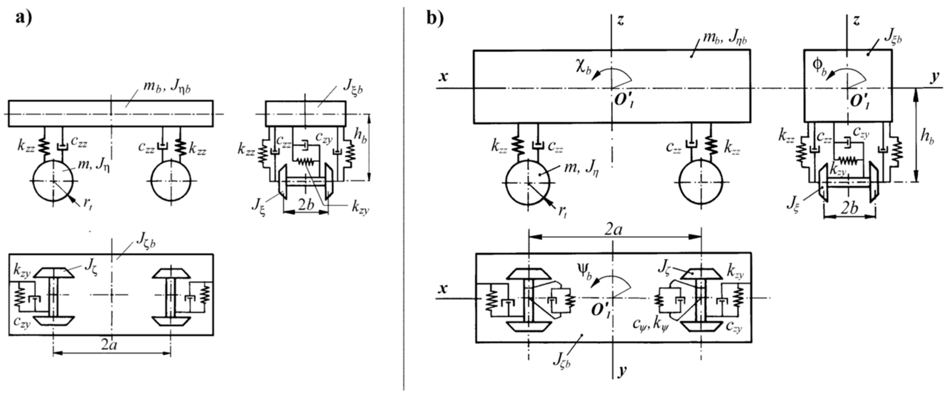
The structure of the studied 2-axle bogies is shown in Figure 2a [2], while of the 2-axle freight cars in Figure 2b [3,5]. Actually, the structure of the bogie of passenger car MKIII, bogie of averaged parameters, and both 2-axle freight cars is the same. It means the same number of DOFs, which together with track equals 18. The exception is the structure of the 25TN bogie of freight cars. Here, the number of DOFs equals 16. Two constraints that reduce this number from 18 to 16 are those causing yaw rotation of wheelsets relative to bogie frame impossible.
The structure of the 4-axle passenger car MKIII is shown in Figure 3 [1,5,21]. Including the track model, it has 38 DOFs.
The structure of the track model’s lateral flexibility is shown in Figure 4a [5,29], while the model’s vertical flexibility is shown in Figure 4b [5,29]. The model of track flexible laterally increases the DOFs by 1 for each wheelset, compared to the stiff track model. The model of track flexible vertically increases the DOFs by 2 for each wheelset and reduces them by 2 at the same time due to constraints in a wheelset–track system [5]. Finally, both track models increase the DOFs by 1 for each wheelset existing in the vehicle, as compared to the stiff track model.
The most convenient source of parameters for the above models of objects of railway vehicle class as well as the track is [2]. All the parameters are collected there. On the other hand, the primary sources for these parameters are earlier publications [3,5].
Tangential contact forces in the vehicle models are non-linear and calculated with the use of a simplified theory of rolling contact as described in [30] and implemented in the FASTSIM program. Non-linear contact geometry taking account of real wheel and rail profiles is calculated according to [31] in a form implemented in the RSGEO program.
A generalized approach to modelling is applied in terms of conditions of motion, i.e., the same model of a particular system is used in straight track, circular curve, and transition curve sections. Proper adaptation of the model to these different conditions is achieved by kinematical quantities determined for different track shapes correspondingly. All non-linear kinematics terms are included in the dynamical equations of motion, while these latter are built with relative motion methods. This enables taking account of the inertia terms arising from motion in a curved track (circular and transition sections) very accurately. It obviously also includes centrifugal forces. These issues are broadly described and explained in [32]. The lateral components in a track plane of the gravity forces due to superelevation are obviously taken into consideration as well. The components crucially important for the proper curving dynamics description are those in the longitudinal and spin creepages that take account of the track curvature. These are, of course, taken into consideration in the equations of motion. Thanks to them the creep forces, especially longitudinal ones governing vehicle dynamics, are properly adapted to conditions of motion in a curved track.

4.3. Conditions of the Critical Velocity Determination and Example Simulation Results

Conditions under which non-linear critical velocity vn has been determined are presented in Table 1 and Table 2. Table 1 and Table 2 show the route parameters for which the tests were performed, i.e., for the bogies and 2-axle vehicles, respectively. The route consisted of ST only in the case of determining the critical velocity for ST. On the other hand, in the case of determining the critical velocity for a CC, that section was preceded by ST and TC.
The model was subject to excitations in the form of initial conditions, i.e., at the beginning of the ST section, which here were almost always yi(0) = 0.0045 m, a value imposed on lateral displacements of wheelsets, bogie frames, and vehicle body. This concerns both vn determination in ST and CCs. The choice of such value arises from the already stated experience and knowledge of the objects’ properties gathered in the earlier studies. Results in [1,3,5,8,9,14,15,16,21] showed that such a value is enough high to start periodic motion if it exists. The higher values of the initial conditions give a bigger chance for the system to take periodic behaviour than the smaller ones that could lead to stationary behaviour in the range vn < v < vc. As explained in Section 4.1, variation of the initial condition was performed in case of doubts, too. The length of ST was always l = 500 m. The length of CC was always l = 500 m. The radii R of the curve ranging from R = 300 m to R = 10,000 m were tested, with exact discrete values R = 300, 600, 900, 1200, 2000, 4000, 6000, and 10,000 m. The superelevation h was chosen so that the equilibrium between lateral components in the track plane of gravity and centrifugal forces was provided at velocity v, being the maximum velocity allowed by regulations in the CC of R = 600 m. If the value of h calculated this way exceeded the maximum allowed value (hmax = 150 mm) then hmax was applied. The interesting and justifying result in this context by the lead author is presented in [14]. It was shown that taking the variable h guarantees the equilibrium in each simulation, i.e., for each value of velocity v does not influence values of the critical velocities in ST and CC of different radii R. It was actually done for the hsfv1 car also studied in the present paper. Moreover, such h adoption leads to unnaturally high values, exceeding those allowed by regulations several times. This fact triggered strong criticism from railway practitioners. Indeed, the superelevation of the real track cannot be freely changed during exploitation. All these caused the authors to resign from this idea and take the superelevation value as it is done in this paper.
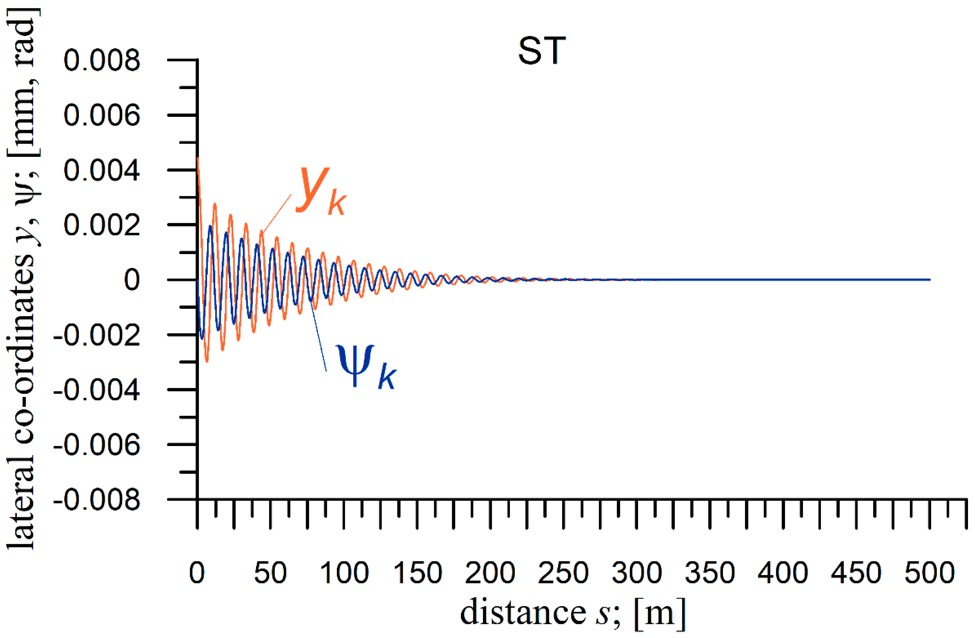
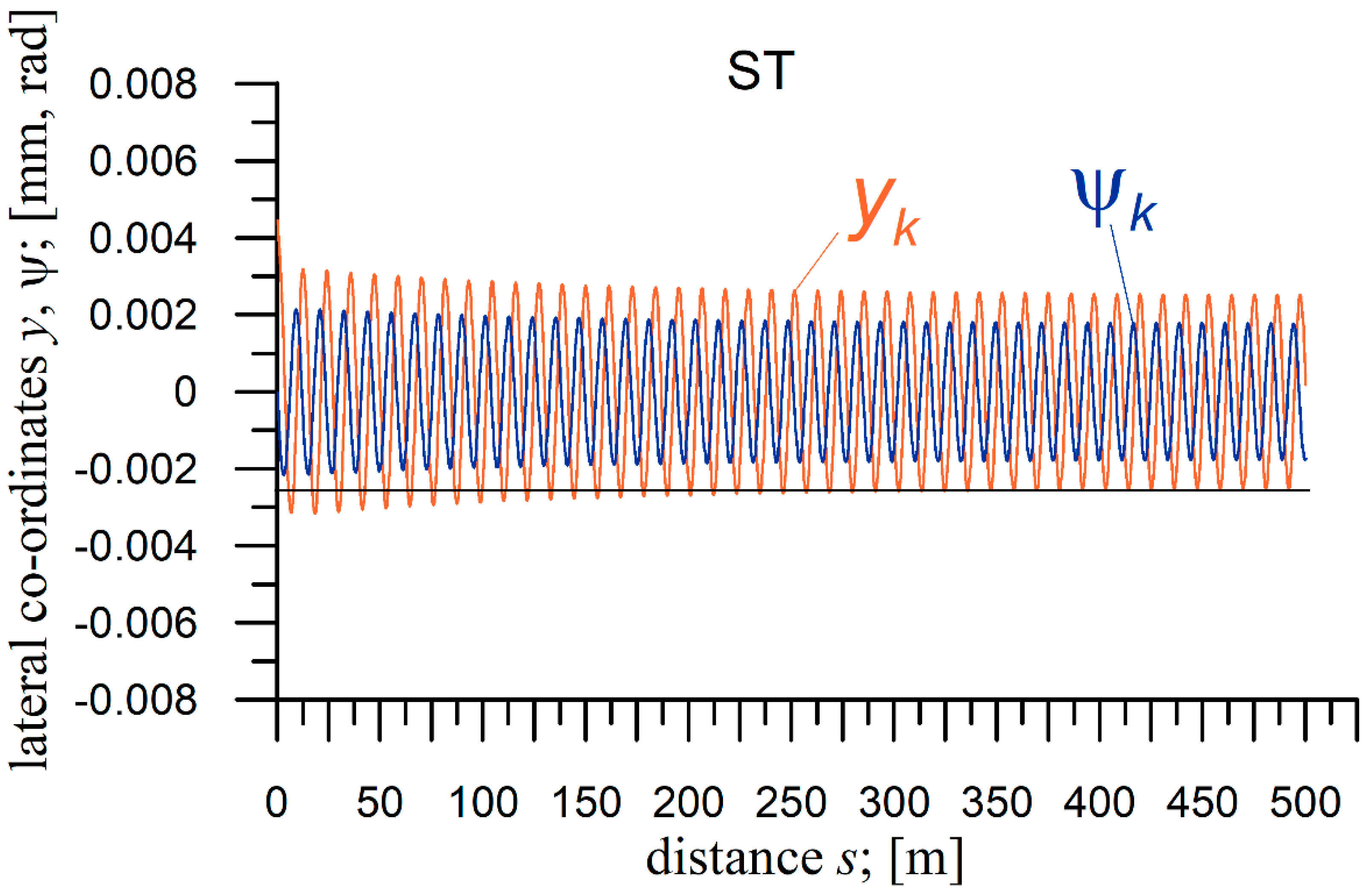
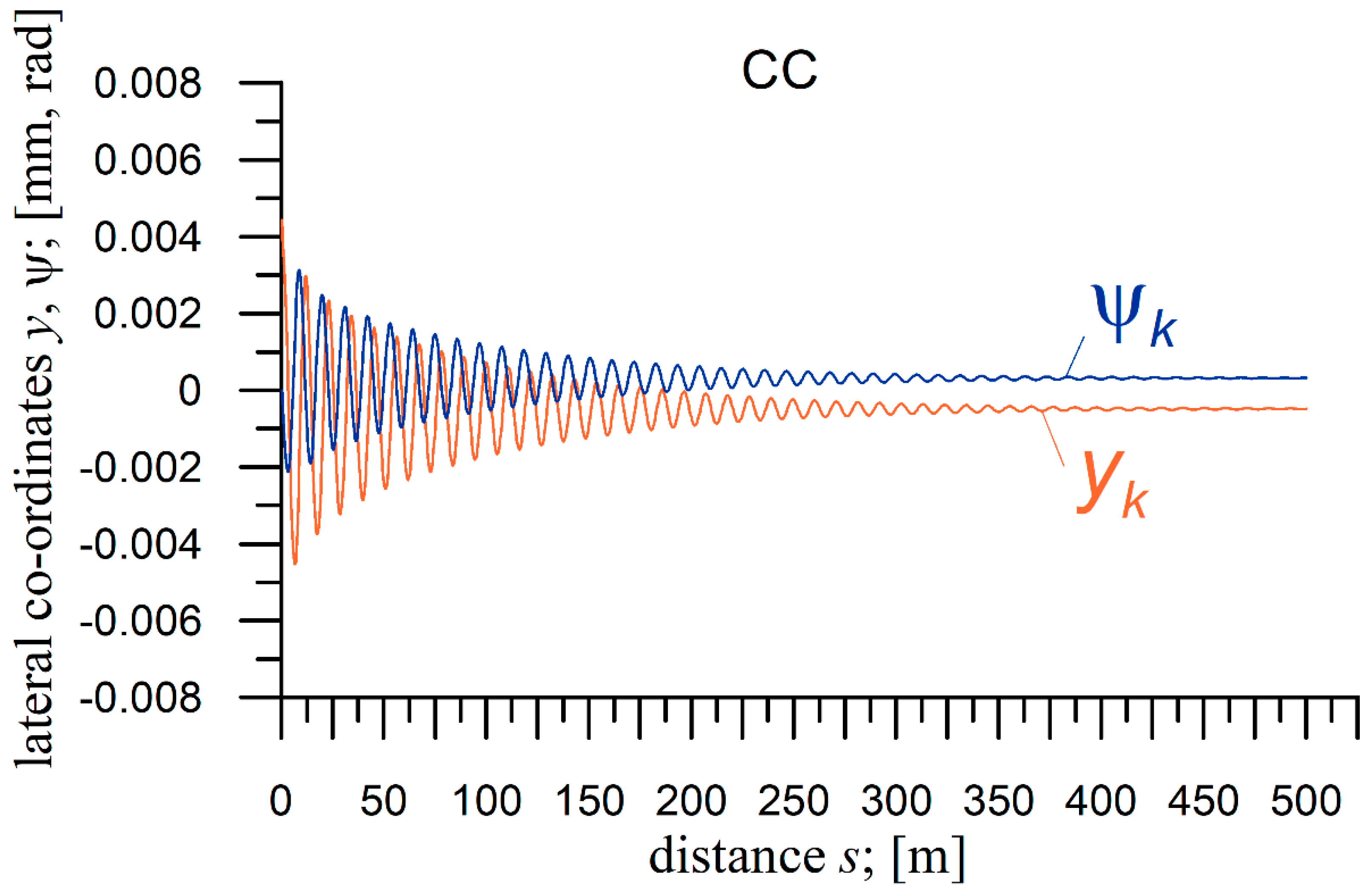
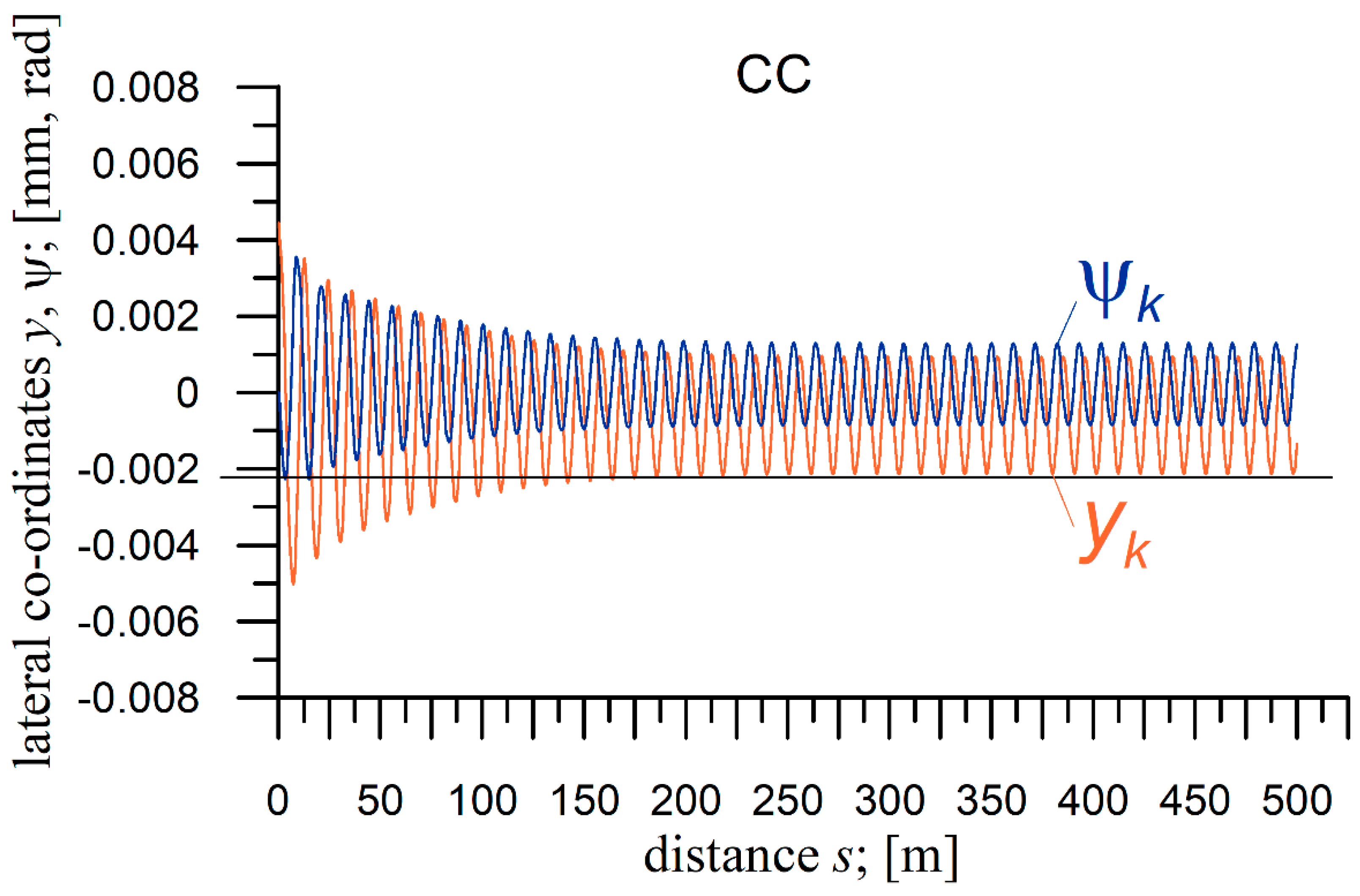
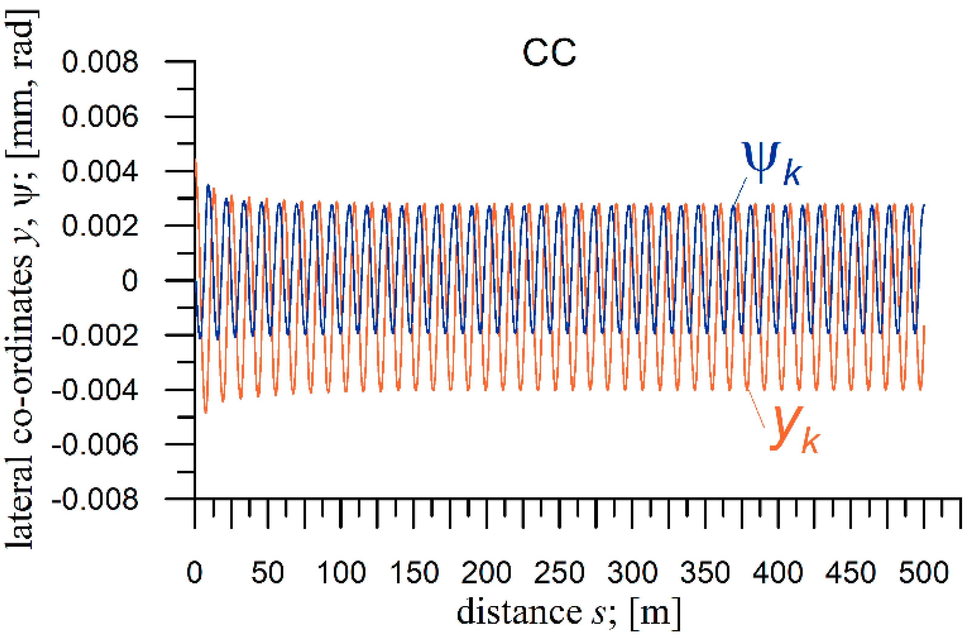
In order to better visualize the technique of critical velocity determination, the present subchapter also includes six exemplary graphs (simulation test results) for a bogie of the MKIII car. The first three are obtained for an ST (Figure 5, Figure 6 and Figure 7), while the second three are for a CC (Figure 8, Figure 9 and Figure 10). Results in Figure 5, Figure 6, Figure 7, Figure 8, Figure 9 and Figure 10 represent vehicle lateral dynamics coordinates. These are lateral displacements y and yaw angles ψ. The index accompanying just mentioned coordinates is k which refers to the trailing wheelset. Formally, all the wheelsets must be observed. However, the one or ones producing the lowest vn are decisive. Similar graphs were made for all the objects for ST and CCs sections of different R for conditions and parameters given in Table 1 and Table 2. They were also made for the range of the object’s velocity v. However, due to paper volume limitation, just three velocities for the above-mentioned graphs were selected for ST and three for CC. In each tire, in some of the figures, the velocities are selected to be in order lower, equal, and higher than the critical velocity. Moreover, Figure 8, Figure 9 and Figure 10 have a simplified form. They represent motion in CC only, while in fact the compound route of ST, TC, and CC was used when vn was determined in CC. The horizontal lines in Figure 6 and Figure 9 make it possible to recognize the stable periodic solution (limit cycle). On that occasion, one can note that solutions in Figure 5, Figure 6 and Figure 7 (ST), including limit cycle, are symmetrical relative to the track centre line, while in Figure 8, Figure 9 and Figure 10 (CC) are shifted laterally i.e., are asymmetric relative to the track centre line.
Figure 6 and Figure 9 actually show the source results for the critical velocity vn determination. According to the definition in Section 2, the value of vn is indicated by the figure in Figure 6 or Figure 9, obtained at the smallest velocity for which a stable periodic solution still exists. In Figure 6, Figure 7, Figure 9 and Figure 10 the limit cycles (stable periodic solutions) can be observed. Their amplitudes are higher for the higher velocities. In Figure 5 and Figure 8, stable stationary solutions appear resulting from the decaying vibrations.

4.4. Results of the Critical Velocity Determination

The values of the velocity vn determined in the studies have been presented in Table 3 and Table 4. These tables show the results for five tested vehicles, i.e., for three bogies and two 2-axle vehicles, respectively. The values of vn in Table 3 and Table 4 obviously match the conditions specified in Table 1 and Table 2, correspondingly.
For the sake of correctness, it should be noted that the results for the hsfv1 car have been obtained for a reduced value of the longitudinal stiffness in the primary suspension, kzx = 206.7 kN/m. For the nominal stiffness, the kzx = 2067 kN/m value of the critical velocity in the ST vn = 64.5 m/s [3].
In order to make the analysis of the results for vn easier, Figure 11 and Figure 12 were elaborated on based on data from Table 3 and Table 4, respectively. The changes in the value of vn depending on the CC radius R are illustrated in Figure 11 and Figure 12 for the bogies and 2-axle vehicles, respectively.
Additional results for the 4-axle MKIII passenger car invoked from [1] are shown in Figure 13. The result for this vehicle is limited to a graphic illustration of the changes in vn depending on the radius R shown. To make the information complete it has to be noted that this result was obtained for the higher than the nominal value of the longitudinal stiffness in the secondary suspension, kpzx = 1000 kN/m. For the nominal value, kpzx = 10 kN/m, while [1] gives the critical velocity vn for the ST only. It is vn = 19.1 m/s. This result was confirmed by these authors’ own study. Moreover, the study by the authors determined the value of vn of the MKIII vehicle with nominal parameters in the CC of R = 600 m as vn = 40 m/s.

5. Discussion of the Results and Conclusions

5.1. Detailed Discussion of the Results

As mentioned earlier in the paper, the first (simplified) method was used with some elements of the second (extended) method to determine the non-linear critical velocities vn for five objects (three bogies and two 2-axle wagons). As a result, it was possible to determine these velocities relatively quickly, and the method turned out to be very effective. On the other hand, the results of vn in [1] for the MKIII passenger car invoked in the present paper were also obtained based on the combination of the first and second methods of vn determination. A similar conclusion can be formulated from [1], then.
In the first group of tests concerning bogies (Table 3), for the bogie of the MKIII car and the curve radii R= 600, 900, 1200, 2000, 4000, 6000 and 10,000 m, the results of the critical velocity values in a circular curve were successfully obtained. For the smallest radius, the value of the critical velocity is the lowest one and amounts to vn= 35 m/s. As the radius increases, the values of this velocity also increase. The increase is initially faster, and then at the larger curve radii, it is slower to finally reach the value of vn = 45.2 m/s for the largest curve radius R. However, in the range of the radii of the curve from R = 1200 m to R = 10,000 m, the difference in the values of the critical velocities is small and amounts up to only 1.2 m/s (see also Figure 11). The velocity vn for ST was also successfully found as vn = 45.5 m/s. It is visible both in Table 3 and Figure 11. One should also realize that result v = vn= 44.0 m/s for R = 2000 m shown in Figure 9 as well as result v = vn= 45.3 m/s for ST shown in the Figure 6 do coincide with the results in Table 3 and Figure 11. One can conclude from all these sources that critical velocity for bogie of MKIII car is in ST higher (Figure 6, Table 3, and Figure 11) than vn values for all curve radii R (Figure 9, Table 3, and Figure 11).
For the second tested bogie, the bogie with averaged parameters, the results are inconsistent and somewhat surprising (Table 3). Initially, for the two CCs with the smallest values of the curve radius, i.e., R = 600 and 1200 m (no tests were performed for R = 900 m), the vehicle numerically derailed before a periodic solution appeared. It happened so for the smaller radius at v = 42 m/s, and for the larger radius at v = 59 m/s. It also means that the critical velocity vn was not reached. It might be a bit surprising that for the next radius R = 2000 m the critical velocity vn = 47.1 m/s was obtained while it is lower than the derailment velocity for the radius R = 1200 m. The successive values of critical velocities obtained for successively increasing radii are decreasing, which is still strange (see also Figure 11). One could rather expect that the greater the radius R, the higher the value of the critical velocity vn. A similar rather unexpected result was also obtained in the group of 2-axle vehicles. The potential for such a feature was also revealed in [2] for the 25TN bogie. The reasons, or rather conditions, favourable to such a feature have not been explained by the authors yet. So, for R = 4000 m—vn = 46.3 m/s, R = 6000 m—vn = 45.8 m/s, and for R = 10,000 m—vn = 45.2 m/s. For the ST, the critical velocity vn = 45.8 m/s and is equal to the critical velocity for a CC with the R = 6000 m and lower than the critical velocity for the largest CC of R = 10,000 m (Figure 11). Again, such a result is not obvious but rather surprising. On the other hand, the differences between vn for ST and CC of R = 6000 and 10,000 are not big. In addition, the critical velocity values for this object can be described as relatively high for the whole range of the periodic solutions’ existence.
For the third bogie, namely, the 25TN bogie, values of the critical velocities are really constant. Regardless of the radius of the circular curve, the value of the critical velocity is alternately either vn = 29.1 m/s or 29.2 m/s (Table 3). Considering this feature, the critical velocity for the ST does not seem to be a surprise. Its value is vn = 29.2 m/s (see also Figure 11).
In the second group of tests for 2-axle vehicles (Table 4), for the hsfv1 car and radii R from 300 to 10,000 m, rather expected values of critical velocities in a circular curve were obtained. For the smallest radius R = 300 m, the vehicle derailed numerically at v = 39 m/s. This is an expected result for such a tight circular curve. For the next tested radius, R = 600 m, the critical velocity is vn = 40 m/s and then vn grows with the increase of the radius R, which is a rather obvious feature. The difference in the values of the critical velocities is small and amounts up to 2.6 m/s for the entire range of the tested circular curves (see also Figure 12). The critical velocity for ST is vn 42.6 m/s, which is 0.2 m/s higher than the largest radius tested R = 10,000 m (see Figure 12). For this vehicle, the behaviour is described as predictable and the graph of the critical velocity values is similar to that obtained for the bogie of the MKIII car (compare Figure 12 to Figure 11).
For the second tested 2-axle railway vehicle, the vehicle with average parameters (Table 4), the results are inconsistent and somewhat surprising. For the smallest curve radius R = 300 m, the vehicle derails numerically at the velocity of v = 10.2 m/s. For the next value of the CC radius R = 600 m, we yet obtain the critical velocity of vn = 41.0 m/s. The same critical velocity is obtained for two successive circular curve radii R = 900 and 1200 m. Then, starting from CC with the radius of R= 2000 m, the critical velocity decreases with the increase of the radius. The lowest value of the critical velocity is for the radius R = 10,000 m and it is vn = 40.0 m/s (see also Figure 12). The same value of the critical velocity was obtained for ST. These results are rather surprising, because for this vehicle, by analogy to the hsfv1 car, the highest velocity vn in ST was expected. Thus, that result is opposite to the generally expected situation. Moreover, an increase of vn with R increase in the range R = 2000 to 10,000 m would also be expected, by the same analogy to the hsfv1 car.
As a supplement to the results discussed above obtained for the five tested objects, the paper invoked results [1] obtained previously for the sixth vehicle, namely the 4-axle MKIII passenger car (see Figure 13). Here we are dealing with completely different solutions. First, for small values of the radii of the curve, the critical velocity vn increases with the R increase, reaching the highest value for the radius R = 2000 m. Then it begins to decrease with the increase of the radius R. The lowest velocity vn = 36.5 m/s was recorded for ST i.e., for R = ∞ (see Figure 13).

5.2. General Conclusions

The most varied results obtained in the studies are those for the car bogies. The best proof of that is the entirely different shapes of the courses in Figure 11. The change of vn versus R has got convex shape for the bogie of the MKIII passenger car. Opposite it, the shape of the bogie with averaged parameters is convex. To make the matter even more complicated, the shape of the 25TN bogie of a freight car is a horizontal line, which means a constant vn value in the whole range of R, including ST. The 25TN bogie has a slightly different structure than the other two bogies, which could potentially explain the difference. On the other hand, the most surprising is the difference between the bogie of the MKIII car and the bogie with averaged parameters. They both have the same structure and differ in their parameters only. Generally, these differences might be subjectively recognized as rather small.
Some similarities to the group of bogies can be seen in the group of 2-axle freight cars, namely the hsfv1 and that with averaged parameters. They both have the same structure and differ in the parameters only. Again, the differences in the parameters could be treated as small. This result and the result for two bogies of the same structure might prove that even small differences in the vehicle parameters can have a significant influence on the critical velocity change not only for ST (to what extent is not known) but also for the entire range of CC radii R, including ST (R = ∞).
The result for the 4-axle passenger car is different than for all bogies and 2-axle cars. That, of course, makes trials for some generalizations even more difficult. The initial increase, next maximum value, and then decrease of vn with the R increase is unique among all objects of the railway vehicle class considered in the present paper. Interesting, here, might be looking at the results of the isolated bogie of the MKIII car (Figure 11) and the complete MKIII car possessing two such bogies (Figure 13). Unfortunately, the shapes of courses in these objects are entirely different. Even critical velocities in ST vary for both these objects considerably, i.e., equal 45.3 and 36.5 m/s, respectively. This confirms the importance of the secondary suspension in the case of 4-axle vehicles equipped with bogies.
The authors noted some similarities between individual vehicles in different groups of results. In the first group (bogies), the expected critical velocity plot was obtained for the bogie of the MKIII car. A graph with a similar course of vn increasing with R increase was also obtained in the second group of objects (2-axle vehicles) for the hsfv1 car. In turn, unexpected results were obtained for the bogie with average parameters (bogie) and vehicle with average parameters (car). In both cases, with the increase of the radius R, the critical velocity vn decreased and corresponding graphs follow a similar course, they are just decreasing. Some but a slight exception, here, is the result for bogie with averaged parameters in ST. The third case was obtained for one object, namely the 25TN bogie. There, the graph resembles a straight line, parallel to the x-axis, which means the results are almost identical. The fourth type of plot is obtained for the 4-axle MKIII car. It can be described as two-stage one, initially increasing and then decreasing with the R increase. Summing up, it is unfortunately not possible to generalize these test results to all vehicles or a group of vehicles, because the results are too varied for individual vehicles and for vehicles within the groups as well.
It seems that further, deeper studies with an intensive variation of the objects’ suspension parameters, either performed separately for vn or in conjunction with wider stability studies, could bring some explanation and, thus, a better understanding of the diversity of the result obtained in the present paper.

Author Contributions

K.Z. and M.G.-S. equally contributed to the simulation, data analysis, and writing. All authors have read and agreed to the published version of the manuscript.

Funding

This research received no external funding.

Institutional Review Board Statement

Not applicable.

Informed Consent Statement

Not applicable.

Data Availability Statement

Not applicable.

Conflicts of Interest

The authors declare no conflict of interest.

References

  1. Zboinski, K.; Dusza, M. Bifurcation analysis of 4-axle rail vehicle models in a curved track. Nonlinear Dyn. 2017, 89, 863–885. [Google Scholar] [CrossRef]
  2. Zboinski, K.; Golofit-Stawinska, M. Investigation into nonlinear phenomena for various railway vehicles in transition curves at velocities close to critical one. Nonlinear Dyn. 2019, 98, 1555–1601. [Google Scholar] [CrossRef] [Green Version]
  3. Zboiński, K. Dynamical investigation of railway vehicles on a curved track. Eur. J. Mech. Part A Solids 1998, 17, 1001–1020. [Google Scholar] [CrossRef]
  4. Knothe, K.; Bohm, F. History of Stability of Railway and Road Vehicles. Veh. Syst. Dyn. 1999, 31, 283–323. [Google Scholar] [CrossRef]
  5. Zboinski, K. Nieliniowa Dynamika Pojazdow Szynowych w Luku; Wydawnictwo Naukowe Instytutu Technologii Eksploatacji-Państwowego Instytutu Badawczego (ITE PIB): Warszawa-Radom, Poland, 2012; p. 371. ISBN 98-83-7789-129-2. [Google Scholar]
  6. Knothe, K.; Stichel, S. Rail Vehicle Dynamics; Springer: Cham, Switzerland, 2017. [Google Scholar]
  7. Ding, W. Self-Excited Vibration: Theory, Paradigms, and Research Methods; Springer: Berlin/Heidelberg, Germany, 2012; p. 399. ISBN 978-3540697404. [Google Scholar]
  8. Zboinski, K.; Dusza, M. Self-exciting vibrations and Hopf’s bifurcation in non-linear stability analysis of rail vehicles in curved track. Eur. J. Mech. Part A Solids 2010, 29, 190–203. [Google Scholar] [CrossRef] [Green Version]
  9. Zboinski, K.; Dusza, M. Extended study of rail vehicle lateral stability in a curved track. Veh. Syst. Dyn. 2011, 49, 789–810. [Google Scholar] [CrossRef]
  10. Gasch, R.; Moelle, D. Nonlinear Bogie Hunting. In Proceedings of the 7th IAVSD Symposium on Dynamics of Vehicles on Roads and Tracks, Cambridge, UK, 7–11 September 1981; Swets & Zeitlinger: Lisse, The Netherlands, 1982; pp. 455–467. [Google Scholar]
  11. Goodall, R.M.; Iwnicki, S. Non-linear Dynamic Techniques v. Equivalent Conicity Methods for Rail Vehicle Stability Assessment. In Proceedings of the 18th IAVSD Symposium on Dynamics of Vehicles on Roads and Tracks, Vehicle System Dynamics, Kanagawa, Japan, 24–30 August 2003; Taylor & Francis: London, UK, 2004; Volume 41, pp. 791–799. [Google Scholar]
  12. Hoffmann, M. Dynamics of European Two-Axle Freight Wagons; Technical University of Denmark, Informatics and Mathematical Modelling: Lyngby, Denmark, 2006. [Google Scholar]
  13. Xu, G.; Steindl, A.; Troger, H. Nonlinear stability analysis of a bogie of a low-platform wagon. Veh. Syst. Dyn. 1992, 20 (Suppl. S1), 653–665. [Google Scholar] [CrossRef]
  14. Zboinski, K.; Dusza, M. Analysis and method of the analysis of non-linear lateral stability of railway vehicles in curved track. Veh. Syst. Dyn. 2004, 41, 222–231. [Google Scholar]
  15. Dusza, M. The study of track gauge influence on lateral stability of 4-axle rail vehicle model. Arch. Transp. 2014, 30, 7–20. [Google Scholar] [CrossRef]
  16. Zboinski, K.; Dusza, M. Development of the method an analysis for non-linear lateral stability of railway vehicles in curved track. Veh. Syst. Dyn. 2006, 44 (Suppl. S1), 147–157. [Google Scholar] [CrossRef]
  17. True, H.; Jensen, J.C. Chaos and asymmetry in railway vehicle dynamics. Period. Polytech. Ser. Transp. Eng. 1994, 22, 55–68. [Google Scholar]
  18. Schupp, G. Computational Bifurcation Analysis of Mechanical Systems with Applications to Railway Vehicles. In Proceedings of the 18th IAVSD Symposium on Dynamics of Vehicles on Roads and Tracks, Vehicle System Dynamics, Kanagawa, Japan, 24–30 August 2003; Taylor & Francis: London, UK, 2004; Volume 41, pp. 458–467. [Google Scholar]
  19. Iwnicki, S. Handbook of Railway Vehicle Dynamics; CRC Press: Boca Raton, FL, USA; Taylor & Francis Group: Oxfordshire, UK, 2006. [Google Scholar]
  20. Hoffmann, M.; True, H. The dynamics of European two-axle railway freight wagons with UIC standard suspension. Veh. Syst. Dyn. 2008, 46 (Suppl. S1), 225–236. [Google Scholar] [CrossRef]
  21. Dusza, M.; Zboinski, K. Comparison of Two Different Methods for Identification of Railway Vehicle Critical Velocity. In Proceedings of the 12th Mini Conference on Vehicle System Dynamics, Identification and Anomalies, Budapest, Hungary, 8–10 November 2010; pp. 161–170. [Google Scholar]
  22. True, H. Multiple attractors and critical parameters and how to find them numerically: The right, the wrong and the gambling way. Veh. Syst. Dyn. 2013, 51, 443–459. [Google Scholar] [CrossRef]
  23. Iwnicki, S.; Stichel, S.; Orlova, A.; Hecht, M. Dynamics of railway freight vehicles. Veh. Syst. Dyn. 2015, 53, 995–1033. [Google Scholar] [CrossRef] [Green Version]
  24. Toumi, M.; Chollet, H.; Yin, H. Effect of Elasto-Plasticity on the Creep Force Characteristic and the Railway Vehicle Stability. In The Dynamics of Vehicles on Roads Track; CRC Press: Boca Raton, FL, USA, 2016; pp. 1015–1025. [Google Scholar]
  25. Schiehlen, W. Dynamical Analysis of Vehicle Systems: Theoretical Foundations and Advanced Applications; Springer Wien: New York, NY, USA; Udine, Italy, 2007. [Google Scholar]
  26. True, H. Does a Critical Speed for Railroad Vehicles Exist? In Proceedings of the ASME/IEEE Joint Railroad Conference, Chicago, IL, USA, 22–24 March 1994; pp. 125–131. [Google Scholar]
  27. True, H. On the theory of nonlinear dynamics and its applications in vehicle systems dynamics. Veh. Syst. Dyn. 1999, 31, 393–421. [Google Scholar] [CrossRef]
  28. True, H. Recent advances in the fundamental understanding of railway vehicle dynamics. Int. J. Veh. Des. 2006, 40, 251–264. [Google Scholar] [CrossRef]
  29. Zboinski, K.; Woznica, P. Optimization of railway transition curves’ shape with use of vehicle-track dynamical model. Arch. Transp. 2010, 22, 387–407. [Google Scholar] [CrossRef]
  30. Kalker, J.J. A fast algorithm for the simplified theory of rolling contact. Veh. Syst. Dyn. 1982, 11, 1–13. [Google Scholar] [CrossRef]
  31. Kik, W. Comparison of the behaviour of different wheelset-track models. Vehicle Syst. Dyn. 1992, 20 (Suppl. S1), 325–339. [Google Scholar] [CrossRef]
  32. Zboinski, K. Modelling dynamics of certain class of discrete multi-body systems based on direct method of the dynamics of relative motion. Meccanica 2012, 47, 1527–1551. [Google Scholar] [CrossRef] [Green Version]
Figure 1. Typical bifurcation graph for a wheelset in CC [2].
Sustainability 14 06649 g001
Figure 2. Structure of nominal models of: (a) bogies [2]; (b) 2-axle cars [2,5].
Sustainability 14 06649 g002
Figure 3. Structure of nominal model of MKIII passenger car [1,2,5].
Sustainability 14 06649 g003
Figure 4. Structure of nominal models of track: (a) flexible laterally [5,29]; (b) flexible vertically [5,29].
Sustainability 14 06649 g004
Figure 5. Lateral coordinates y and ψ of the wheelset of the bogie of the MKIII car on the ST section; v = 40.0 m/s < vn; yi(0) = 0.0045 m.
Sustainability 14 06649 g005
Figure 6. Lateral coordinates y and ψ of the wheelset of the bogie of the MKIII car on the ST section; vn = 45.3 m/s; yi(0) = 0.0045 m.
Sustainability 14 06649 g006
Figure 7. Lateral coordinates y and ψ of the wheelset of the bogie of the MKIII car on the ST section; v = 50.0 m/s > vn; yi(0) = 0.0045 m.
Sustainability 14 06649 g007
Figure 8. Lateral coordinates y and ψ of the wheelset of the bogie of the MKIII car on the CC section; R = 2000 m; h = 0.0450 m; v = 40.0 m/s < vn; yi(0) = 0.0045 m.
Sustainability 14 06649 g008
Figure 9. Lateral coordinates y and ψ of the wheelset of the bogie of the MKIII car on the CC section; R = 2000 m; h = 0.0450 m; vn = 44.0 m/s; yi(0) = 0.0045 m.
Sustainability 14 06649 g009
Figure 10. Lateral coordinates y and ψ of the wheelset of the bogie of the MKIII car on the CC section; R = 2000 m; h = 0.0450 m; v = 46.0 m/s > vn; yi(0) = 0.0045 m.
Sustainability 14 06649 g010
Figure 11. Change of the value of the critical velocity vn of the bogies depending on the curve radius.
Sustainability 14 06649 g011
Figure 12. Change of the value of the critical velocity vn of 2-axle vehicles depending on the curve radius; for the hsfv1 car reduced value of longitudinal stiffness in the primary suspension kzx = 206.7 kN/m.
Sustainability 14 06649 g012
Figure 13. Change of the value of the critical velocity vn of 4-axle vehicle depending on the curve radius; the reduced value [14] of longitudinal stiffness of the secondary suspension kpzx = 1000 kN/m.
Sustainability 14 06649 g013
Table 1. The route parameters while determining the critical velocity for the bogies.
ObjectInitial Conditions
yi(0) (m)
ST
Length; l (m)
CC
Length; l (m)
CC
Radius; R (m)
Superelevation
h (m)
Bogie of MKIII car,
Bogie with averaged parameters
0.0045500--0
0.0045-5006000.1500
0.0045-50012000.0750
0.0045-50020000.0450
0.0045-50040000.0225
0.0045-50060000.0150
0.0045-50010,0000.0090
25TN bogie0.0045500--0
0.0045-5003000.1500
0.0045-5006000.1500
0.0045-5009000.1420
0.0045-50012000.0750
0.0045-50020000.0450
0.0045-50040000.0225
0.0045-50060000.0150
0.0045-50010,0000.0090
Table 2. The route parameters while determining the critical velocity for the 2-axle vehicles.
ObjectInitial Conditions
yi(0) (m)
ST
Length
l (m)
CC
Length
l (m)
CC
Radius
R (m)
Superelevation
h (m)
hsfv1 car,
Vehicle with averaged parameters
0.0045500--0
0.0045-5003000.1500
0.0045-5006000.1500
0.0045-5009000.1420
0.0045-50012000.0750
0.0045-50020000.0450
0.0045-50040000.0225
0.0045-50060000.0150
0.0045-50010,0000.0090
Table 3. Values of critical velocities vn of bogies for ST and CCs of different radii.
ObjectST;
vn (m/s)
CC;
R (m)
CC;
vn (m/s)
Bogie of MKIII car45.3--
60035.0
90041.0
120044.0
200044.0
400045.0
600045.1
10,00045.2
Bogie with averaged parameters45.8--
600n. derailment—at 42 *
1200n. derailment—at 59 *
200047.1
400046.3
600045.8
10,00045.2
25TN bogie29.2--
30029.1
60029.1
90029.2
120029.1
200029.1
400029.2
600029.1
10,00029.2
* vehicle velocity for which so-called numerical derailment occurred below the velocity vn.
Table 4. Values of critical velocities vn of 2-axle vehicles for ST and CCs of different radii.
ObjectST
vn (m/s)
CC
R (m)
CC
vn (m/s)
hsfv1 car **42.8--
300n. derailment—at 39.0 *
60040.0
90041.5
120042.0
200042.3
400042.3
600042.4
10,00042.6
Vehicle with averaged parameters40.0--
300n. derailment—at 10.2 *
60041.0
90041.0
120041.0
200040.9
400040.3
600040.1
10,00040.0
* vehicle velocity for which a numerical derailment occurred below the critical velocity vn. ** reduced value of the longitudinal stiffness of in the primary suspension kzx = 206.7 kN/m.
Publisher’s Note: MDPI stays neutral with regard to jurisdictional claims in published maps and institutional affiliations.