Article

Carbonation Resistance in Ordinary Portland Cement Concrete with and without Recycled Coarse Aggregate in Natural and Simulated Environment

Department of Civil Engineering, NED University of Engineering and Technology, Karachi 75270, Pakistan
*
Author to whom correspondence should be addressed.
Sustainability 2022, 14(1), 437; https://doi.org/10.3390/su14010437
Submission received: 26 November 2021 / Revised: 20 December 2021 / Accepted: 21 December 2021 / Published: 31 December 2021

Abstract

:
This research aims to examine the effect of carbonation on the strength properties and carbonation depth of ordinary Portland cement (OPC) concrete using two different water to cement ratios (w/c) and two different replacement percentages of natural coarse aggregate (NCA) with recycled coarse aggregate (RCA). Two concrete mixes were prepared using w/c of 0.4 and 0.43. The two concrete mixes were subdivided into two subgroups based on the use of NCA and 30% RCA. The first concrete mix having w/c of 0.4 was contained NCA and from this concrete, 42 cylinders of 100 mm dia. and 200 mm height were cast. Six out of 42 cylinders served as control specimens and were not exposed to CO2. A total of 18 out of the remaining 36 cylinders was exposed to the simulated environment and the rest were exposed to the natural environment. The second concrete mix having a w/c of 0.4 contained 30% RCA/70% NCA, and using this concrete, 42 cylinders of similar size were cast. A similar scheme was adopted for w/c of 0.43 and, in total, 84 cylinders using four mix designs were cast. After casting and 28 days of curing, six out of 42 cylinders cast from each concrete mix design were tested for compression and splitting tensile strength, following ASTM C39 and ASTM C496 without any exposure to carbon dioxide (CO2). A total of 18 out of the remaining 36 cylinders was exposed to the simulated environment in a carbonation chamber for an equivalent time duration of 90, 180 and 365 days following CEN test guidelines and the other 18 cylinders were kept in the natural environment for a period of 90, 180 and 365 days. After the completion of simulated and natural exposure periods, these cylinders were distributed equally to test for compressive strength and splitting tensile strength to observe the effect of carbon dioxide (CO2) at each time duration (i.e., 90, 180 and 365 days), and replacement percentage of RCA (i.e., 0 and 30%), which showed that carbonation depth increases incrementally with the w/c ratio and CO2 exposure duration. In both the simulated and the natural environment, the use of RCA in concrete cast using a w/c of 0.4 increased carbonation depth up to 38% and 46%, whereas, in the case of the concrete cast using a w/c ratio of 0.43, the use of RCA increased the carbonation depth up to 16% and 25%. In general, the use of RCA in the concrete exposed to the natural environment significantly affected the compressive strength of concrete, due to multiple interfaces and the porous structure of RCA, and the variation in the temperature, humidity and content of carbon dioxide (CO2) present in the actual environment. The maximum compressive strength variation prepared from the mixes M0-0.4, M30-0.43, M0-0.43 and M30-0.43 differed by 5.88%, 7.69%, 16.67% and 20% for an exposure period up to 365 days. Similarly, the results of splitting tensile strength tests on cylinders prepared from the same mixes exposed to the natural environment differ by 7.4%, 27.6%, 25.41% and 18.2% up to 365 days of exposure, respectively, as compared to the simulated environment.

1. Introduction

Reinforced concrete structures have been investigated over the years to study their performance depending on the durability of the material [1,2]. Recently, the performance and reliability of concrete containing recycled coarse aggregate have also been investigated [3,4]. The reported results [3,4] of recycled concrete aggregate (RCA) properties make it acceptable in the construction industry for the production of recycled aggregate concrete (RAC). Although, it has been agreed, in general, by several researchers [3,5] that there is a loss in mechanical and durability properties of RAC as compared to conventional concrete. The reason can be associated with the use of recycled aggregates, which make the microstructure significantly complex and, therefore, the mechanical properties of RAC are somewhat different from normal Portland concrete [6]. In the case of RAC, a variety of interfaces exist in concrete containing RCA, as compared to concrete containing natural aggregates. Furthermore, the interfacial transition zone (ITZ) between the aggregates and the adhered mortar of RCA, and an additional new ITZ between the adhered mortar and the new mortar causes a complicated microstructure of RAC. Thus, it is very challenging to understand the failure mechanism and durability of RAC [6]. Durability, conversely, is an indispensable subject as it permits the understanding of concrete material performance throughout the service life of any structure. It is to be noted that the less durable concrete may prompt external agents from the environment or internal agents within the concrete to attack [7].
Among various degradation phenomena of reinforced concrete, the most important is corrosion of reinforcement, which significantly affects the durability and performance of reinforced concrete structures [8,9]. The hydration process of cement results in alkalinity, which naturally protects reinforcement by forming a passive layer around it, and any chemical or physical change in the alkaline environment of cement paste enables external aggressive agents to act. The two major reinforcement corrosion-initiating phenomena are carbonation and chloride ingress, which destroy the natural passive layer around it [10]. Carbonation, in particular, represents one of the most frequent deterioration mechanisms observed in European structures [11]. This issue has now become newsworthy with the growing concentration of carbon dioxide (CO2) during the past 30 to 40 years.
This study investigates the effect of carbonation on the compressive strength, carbonation depth and pull-out strength of concrete. Carbonation is a frequently diffused phenomenon in old reinforced concrete structures, commonly built without specific design guidelines against degradation. In the carbonation process, the atmospheric carbon dioxide (CO2) enters through the capillary pores of the concrete cover and reacts with calcium hydroxide (Ca(OH)2), which is a hydration product of calcium silicate compounds present in the clinker and is responsible for the pH value reduction causing the formation of calcium carbonate as follows:
Ca(OH)2 + CO2 ⟶ CaCO3 + H2O
Additionally, CO2 may also react with the calcium silicate hydrate (C-S-H) network to form added CaCO3 [12]. The pH of the recycled aggregate is dependent on the amount of Portlandite (Ca(OH)2) in the concrete mass. The pH value of the recycled aggregate rises to 12 and is generally ranged from 11 to 13 due to the dissolution of Ca(OH)2 and the production of OH¯ in water [13]. In the carbonation process, the presence of water is essential for the movement of hydrated cement products in the pore solution and permits the CO2 to dissolve and form carbonic acid (H2CO3). This weak acid attacks Portlandite (Ca(OH)2) and forms CaCO3 using the following mechanism:
Ca(OH)2 + H2CO3 ⟶ CaCO3 + 2H2O
Fung [14] and Silva et al. [15] reported that the carbonation depth of RAC increases with the increase in the replacement percentage of natural aggregates by the recycled aggregates in a concrete mix. Otsuki et al. [16] assessed the effect of the water/cement (w/c) ratio on the carbonation depth of RAC and reported an increase in the carbonation depth with the increase in the w/c ratio. In another study, Ryu [17] reported that there is no clear effect of the properties of RCA (i.e., the quality and the amount of mortar adhered to the RCA) on the recycled aggregate concrete. Salomon and Paulo [18] mentioned that RAC exhibits approximately the same, and occasionally better, carbonation resistance as compared to the same strength of normal concrete. Other researchers [18,19] confirmed the slight inferior carbonation resistance of RAC compared with NAC due to the increased porosity resulting from the high amount of adhered mortar on the surface of RCA. Kou and Poon [20] observed an increase in the carbonation depth with an increasing replacement rate of natural aggregates with recycled aggregates. Xiao et al. [6] reported an increase in the carbonation resistance with the use of 100% RCA, which is conflicting due to other parameters associated with the concrete composition.
From this overview, it can be established that the majority of experiment-based studies carried out were rather random, which is why the reported test results were incomparable with each other. Besides, contradictions were observed among the drawn conclusions in the studies, as carbonation resistance analysis of RAC did not account for the influence of the stress level. Moreover, microscopic cracks caused by the tensile stress increase the pathways of CO2 diffusion in many cases of RAC. As the carbonation behavior of RAC is not yet well agreed upon; therefore, more research is required to understand the resistance of RAC to carbonation activities precisely. This paper is an attempt to contribute to the existing literature in this regard; the effect of the water/cement (w/c) ratio on the compressive strength, carbonation depth and pull-out strength of concrete is analyzed in detail with the help of understanding microstructure.

2. Experimental Program
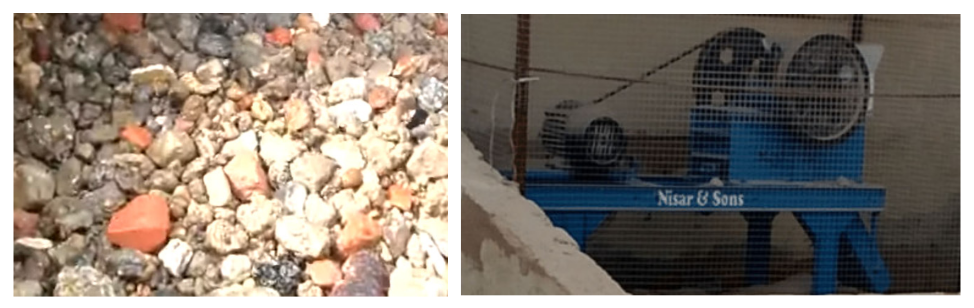
2.1. Materials

Recycled concrete aggregates (RCA) were obtained from the available debris of tested beams used in past research work conducted at the Department of Civil Engineering, NED University of Engineering and Technology. As mentioned by Meng et al. [3], RAC has a greater scattering of properties due to variability of the properties of RCA, therefore, the strength and batch of concrete beams cast to acquire RCA were consistent in this study. The compressive strength of the tested beams to acquire RCA was 20.68 MPa [9] and had no previous exposure to carbonation. The recycled coarse aggregates were crushed in a jaw crusher, as shown in Figure 1.
The crushed product was then used in two sizes. The first size of RCA used was kept between 20 to 15 mm and comprised 40% of the total weight of coarse aggregate, whereas the remaining 60% of the total weight of coarse aggregate was kept between 15 mm and 5 mm in size. The same size and proportion of natural aggregate were used in the preparation of concrete either with or without RCA. A higher proportion, comprised of 15 mm to 5 mm coarse aggregate, was used to achieve a good bond between cement and aggregate by reducing the number of voids in concrete, which eventually results in higher compressive and tensile strength [21]. The physical properties of RCA are mentioned in Table 1.
The specific gravity and water absorption for recycled aggregate were determined as per ASTM C127-15 [22], while crushing value and impact value were determined as per B. 812–110 [23] and ASTM C131-20 [24]. It can be found that crushing value and water absorption percentage for recycled aggregate is not within a standard range, which might be due to the porous structure of RCA. The old mortar adhered to the aggregate is responsible for the high porosity of aggregate [25].
The natural aggregates used for the research work were crushed granite coarse aggregates obtained from a local quarry site. The fine aggregate used was river sand with a fineness modulus of 2.6. The varying amount of Superplasticizer in the range from 1 to 2% was used to achieve the targeted slump of 100 to 125 mm. This slump value was chosen due to the reason that a slump greater than 125 mm is nearer to collapse, and less than 100 mm is unsuitable for closely placed reinforcement bars. The concrete was prepared by following the mixing technique mentioned in ASTM C-192 [26]. Ordinary Portland cement (OPC) meeting ASTM standard for Portland cement Type I [27] and tap water free from impurities were used for the preparation of concrete for this research work.

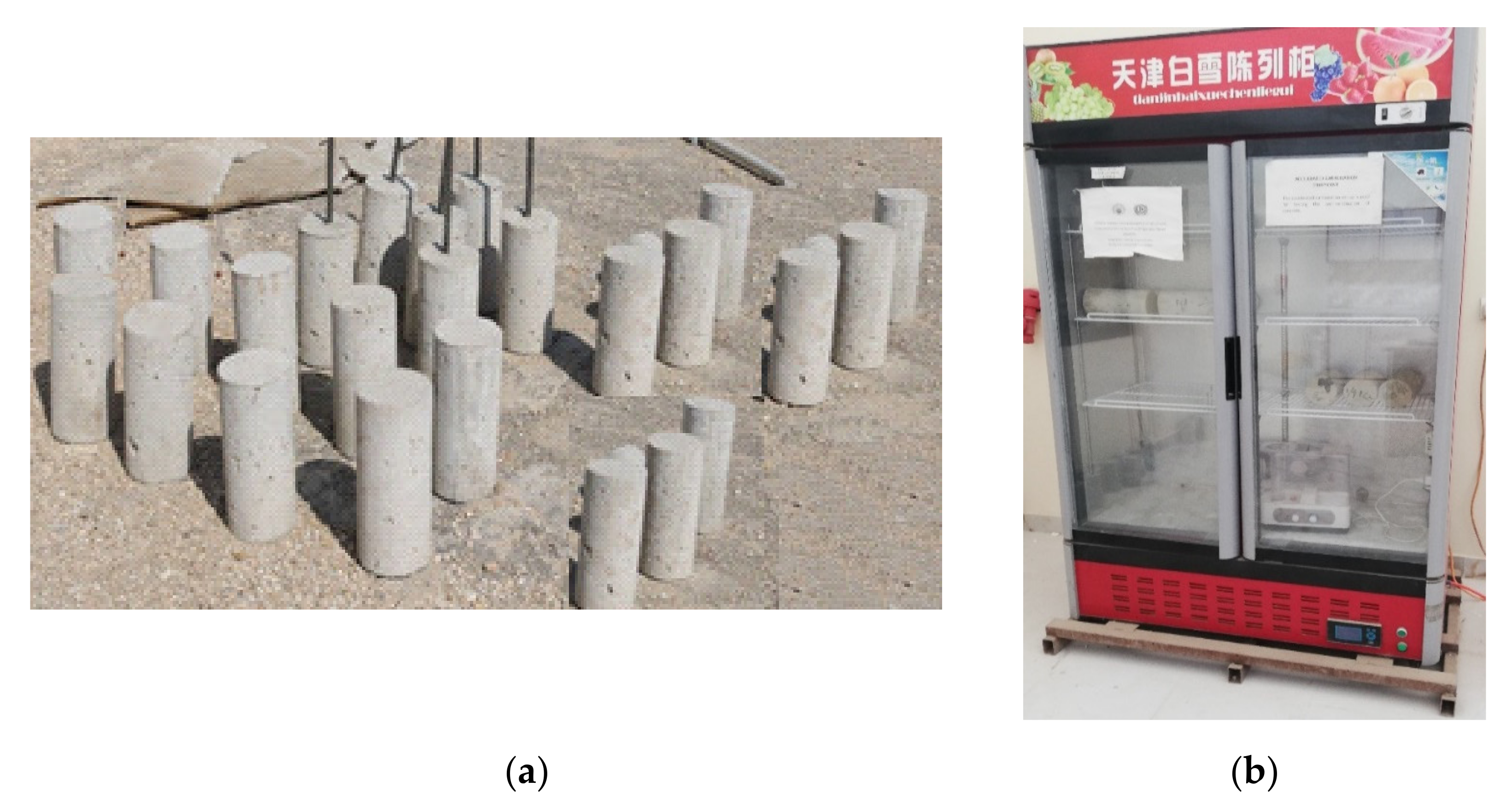
2.2. Mix Design of Concrete and Sample Preparation

Two types of concrete mix batches were prepared using a w/c ratio of 0.4 and 0.43. Each batch is further divided into two subgroups depending on the replacement percentage of RCA, i.e., 0 and 30% or 100% and 70% of NCA. Thus, a total 4 mixes were prepared and named as M0-0.4 (mix containing no RCA or 100% NCA prepared using w/c ratio = 0.4), M30-0.4 (mix containing 30% RCA or 70% NCA prepared using w/c ratio = 0.4), M0-0.43 (mix containing no RCA or 100% NCA prepared using w/c ratio = 0.43) and M30-0.43 (mix prepared using w/c ratio = 0.4 containing 30% RCA or 70% NCA). The mix design is summarized in Table 2. The design mix for a water-cement ratio of 0.43 has been adapted from [28].
Using the mix designs mentioned in Table 2, a total of 168 cylinders were cast in the oiled steel molds of 100 mm dia. and 200 mm height. The detail of the cylinders dedicated for the mechanical properties test is mentioned in Table 3.

3. Exposure Conditions

The concrete cylinders were unmolded after 24 h casting and soaked in a curing tank for a period of 28 days of initial curing. Subsequently, 6 cylinders from each 4 concrete mixes (refer to Table 3) were tested for compression and splitting tensile strength following ASTM C39 [29] and ASTM C496 [30] without exposure to CO2. As mentioned in Table 3, a total of 18 cylinders from each mix design were stored in the carbonation chamber, whereas 18 cylinders were kept in an open environment for a natural exposure of 90, 180 and 365 days. The detail of exposure is further discussed in detail in the next section.

3.1. Simulated Environment

As mentioned earlier, 72 cylinders (18 cylinders from mixes M0-0.4, M30-0.4. M0-0.43 and M30-0.43 were stored in a carbonation chamber at 20 ± 2 °C and 57% relative humidity (RH), as recommended by Leeman and Loser [31] for the simulated environment. The cylinders were exposed to carbon dioxide (CO2) gas of around 350 ± 50 ppm and RH of 65 ± 5%, as recommended by Jones et al. [32] and kept for 33.6, 67.2, and 134.4 h, which is equivalent to the exposure age of 90, 180 and 365 days. It is noteworthy that the exposure period of 11.2 h in the carbonation chamber is equivalent to 1 month as per Jones et al. [32]; therefore, the simulated exposure period of 33.6, 67.2, and 134.4 h is equivalent to 3 months (or 90 days), 6 months (or 180 days) and 12 months (or 365 days). The cylinders placed in the carbonation chamber were unreinforced.

3.2. Natural Environment

For natural exposure, 72 cylinders were placed in an open environment of the Department of Civil Engineering, NED University of Engineering & Technology for 90, 180 and 365 days. The temperature, humidity and content of carbon dioxide (CO2) present in the actual environment were noted 3 times a day, in the morning around 8:30 am, in the evening after 4:00 pm and at night before 9 pm using a thermohygrometer (refer to Figure 2a) and carbon dioxide meter (refer to Figure 2b). The selected timings were assumed as the peak traffic hours of traffic in Karachi. The cylinders placed in simulated or simulated and natural environments are shown in Figure 3. The recorded data for temperature, humidity and CO2 concentration in the atmosphere for the period of 365 days has been summarized in Table 4.
Table 4 shows that the CO2 concentration, temperature and humidity in the natural environment were found to be higher than the parameters kept constant in the carbonation chamber for carbonation curing.

4. Experimental Tests and Results
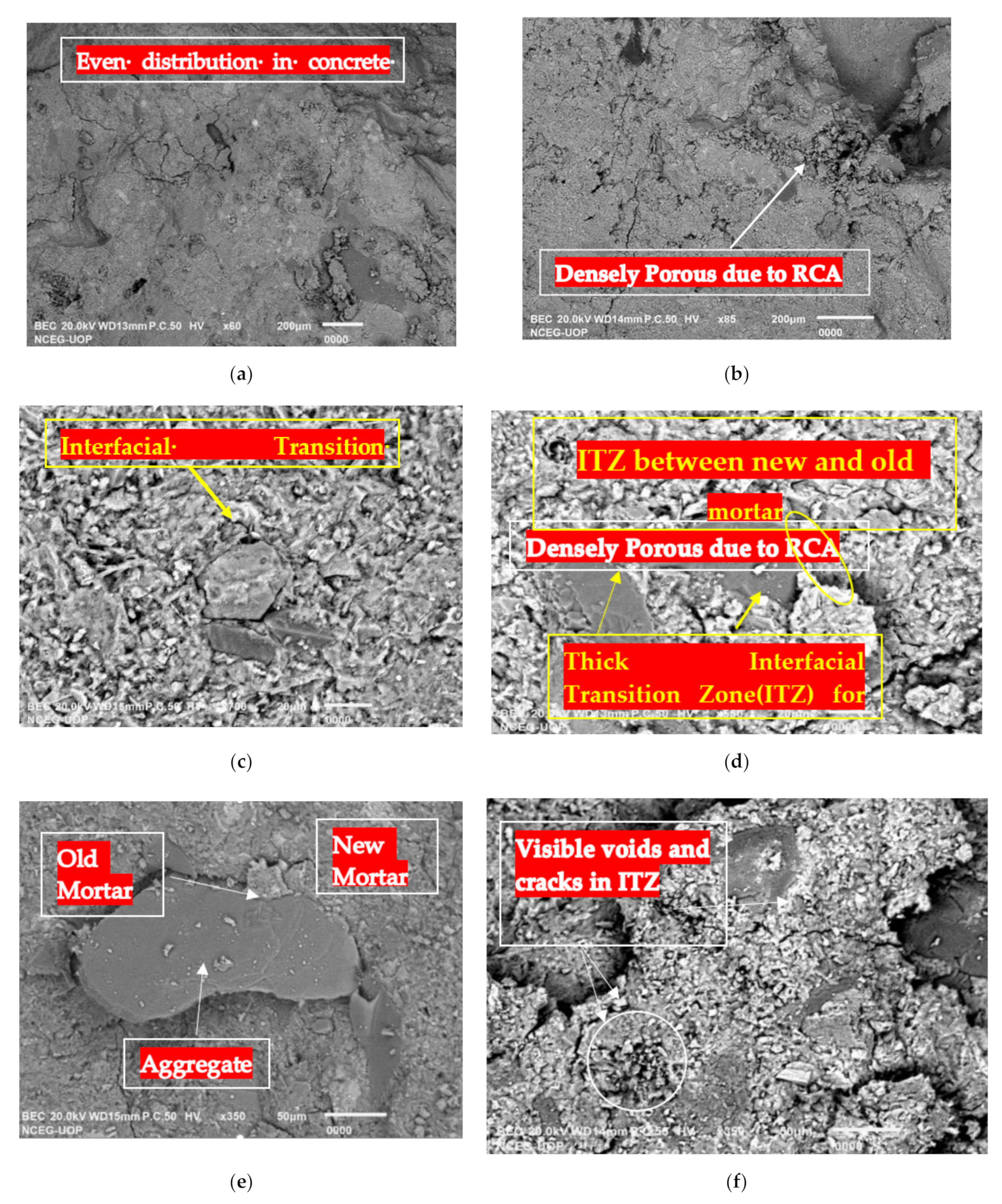
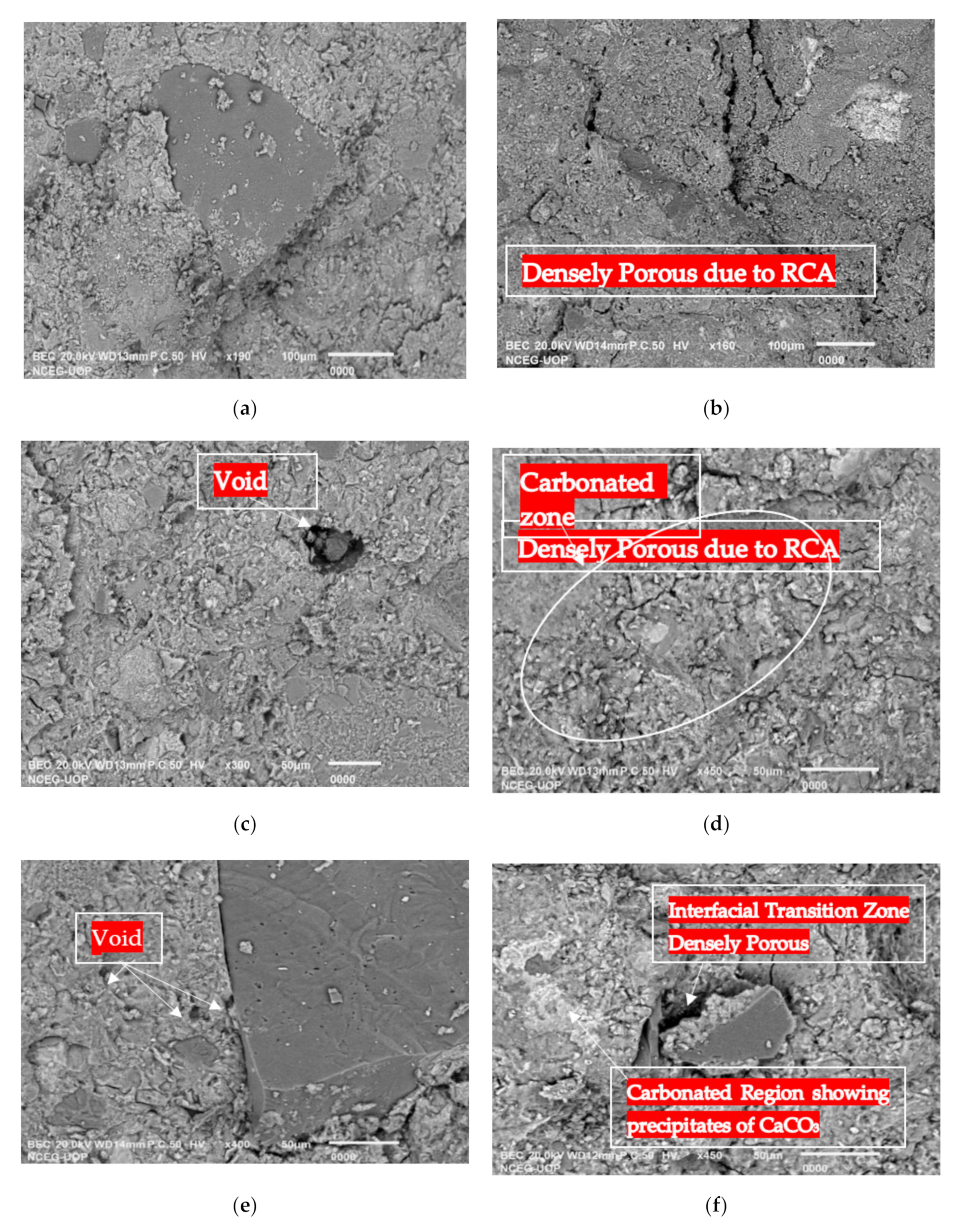
After completion of the curing period, 3 cylinders made from each of the 4 concrete mixes (refer to Table 3) were tested for compression, and the other 3 cylinders were tested for splitting tensile strength following ASTM C39 [29] and ASTM C496 [30] without exposure to CO2. These 6 cylinders were control specimens used to compare the strength results before and after exposure.
After the completion of exposure to the simulated environment for 33.6 h, which is equivalent to a 3 month, 24 cylinders were taken out of the carbonation chamber and tested (i.e., 6 cylinders representative of each mix design) for determining the compressive and splitting tensile strengths following ASTM C39 [29] and ASTM C496 [30]. A similar procedure was followed once the exposure to the simulated environment for 67.2 and 134.4 h, which is equivalent to 6 months (or 180 days) and 12 months (or 365 days) was completed.
After the compression test, the samples of unexposed concrete and concrete exposed to simulated and natural environments were acquired to examine the microstructure, which is presented in the next section. Additionally, phenolphthalein was sprayed on the exposed surfaces of split cylinders after split tension tests to determine the carbonation depth.

4.1. Microstructure

The concrete microstructure was captured using a scanning electron microscope (SEM). The microstructure of non-carbonated and carbonated concretes with and without RCA and produced using w/c ratio of 0.4 and 0.43 is shown in Figure 4 and Figure 5 for an exposure period of 90 days. Figure 4 shows the microstructure of carbonated concrete with and without recycled aggregate with a w/c ratio of 0.4 exposed to simulated and natural environments. The microstructure shown in Figure 6 shows that mixes containing natural coarse aggregates (i.e., M0-0.4) are less porous than those containing 30% RCA. Overall, the microstructure of concrete exposed to a natural environment contains visible pores and cracks in comparison with the natural environment. This may lead to inferior performance and strength results for the mixes exposed to the natural environment. The microstructure of non-carbonated and carbonated concrete with and without RCA produced using a w/c ratio of 0.43 is shown in Figure 5, and a similar observation as indicated in Figure 4 was found. ITZ between cement mortar and aggregate is the most important interface, particularly in the case of recycled aggregate concrete. The reason is that concrete containing RCA has more interfaces than conventional concrete [33]. This includes ITZ between actual aggregate and old mortar and the other interface between the adhered old and new mortar (refer to Figure 4d and Figure 5f).
In Figure 4 and Figure 5, the non-carbonated region of each concrete mix can be visualized at the micro-level for the mixes prepared using a w/c ratio of 0.4 and 0.43. The non-carbonated concrete does not contain any visible cracks and pores, whereas, the ITZ of aggregate seems to be changed in the carbonated samples indicate that penetration of CO2 influences the ITZ of NCA and RCA. Further, the concrete exposed to the natural environment exhibited more porous microstructure as compared to the concrete exposed to the simulated environment, indicating the severity of CO2 in the natural environment; this can be confirmed from Table 4, which shows that CO2 percentage, temperature and humidity content in the natural environment changes and fluctuates daily while these three parameters remained constant in the carbonation chamber. A high humidity allowed CO2 gas to form more carbonic acid after penetrating concrete in a natural environment and as a result, more calcium carbonate (CaCO3) precipitated and can be seen in Figure 4 and Figure 5. The quality of CaCO3 is its finer particles size as compared to the cement particles, which leads to particle packing of concrete but CaCO3 reduces the compressive strength at later ages [34]. The strength comparison of concrete exposed to simulated and natural exposure can be further explained comprehensively after chemical investigation due to the reason that the concrete is exposed to other harmful substances present in the natural environment apart from CO2.
In the case of concrete containing RCA, ITZ is composed of old mortar and new mortar. The old mortar was found to be more porous and cracked, which influenced the mechanical and durability properties of concrete. Similarly, the comparison of microstructure exposed to the simulated and natural environment (refer to Figure 4 and Figure 5) showed that the concrete mixes containing NCA exposed to the simulated environment in the carbonation chamber were found to be less carbonated than concrete containing RCA. The concrete containing RCA resulted in more pores, in general, as compared to the concrete containing RCA, and the ITZ was also affected in this case. Rao et al. [33] also confirmed that concrete containing RCA exhibits more pores and less dense ITZ as compared to the concrete containing NCA.

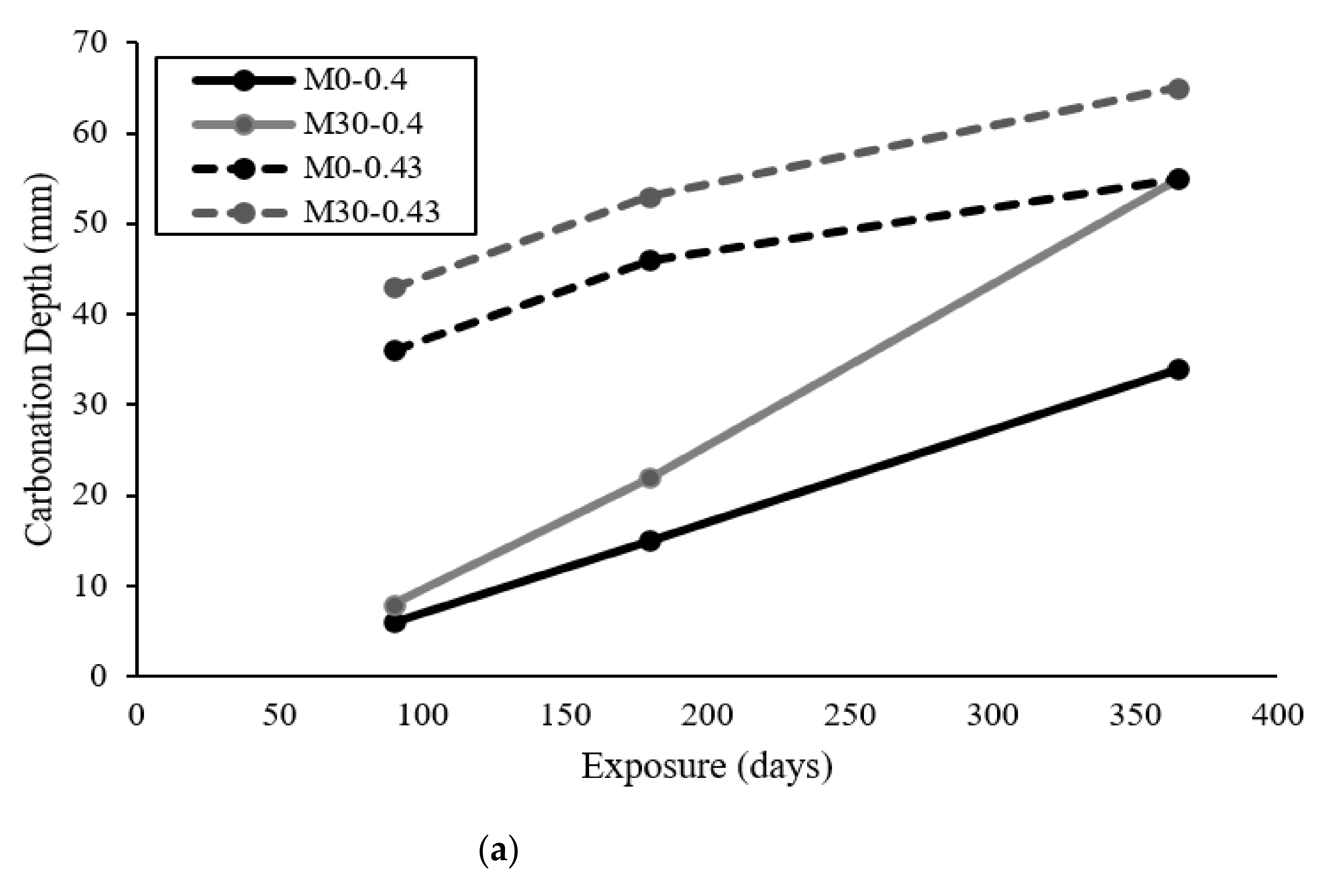
4.2. Carbonation Depth

The 36 cylinders exposed in the carbonation chamber and the natural environment for the duration of 90, 180 and 365 days were split into two pieces under a Universal testing machine (refer to Figure 6a) that tested for splitting tensile strength. The split pieces were used to determine the carbonation depth as per the provision of the CEN test [32]. The phenolphthalein was sprayed on the split pieces of the cylinders exposed to the simulated environment to observe the change in the color from bright pink/purple to colorless or light pink. As shown in Figure 6b, the colorless or light pink region is representative of carbonated concrete; therefore, the depth of the carbonated region was measured using a scale. A typical view of carbonated cylinders exposed to simulated and natural environments is shown in Figure 6c,d). The values of carbonation depth for mixes M0-0.4, M30-0.4, M0-0.43 and M30-0.43 exposed to the simulated and natural environments are shown in Figure 7a,b).
It can be observed in Figure 7 that less carbonation depth was observed in the mix, which was produced using less w/c ratio (i.e., 0.4) and natural aggregates (i.e., Mix M0-0.4), whereas the highest carbonation depth was observed in the mix cast using w/c = 0.43 and recycled concrete aggregates (i.e., Mix M30-0.43). These results are coherent with the results reported in the literature by Fung [14] and Silva et al. [15], who reported that the carbonation depth of RAC increases with the increase in the replacement percentage of natural aggregates by the recycled aggregates in a concrete mix. The increase in the carbonation depth in the case of recycled aggregate can be associated with the porosity of RCA (in the paste adhered with the actual aggregate) which may have a profound influence on the carbonation depth.
The concrete mixes M0-0.4 and M30-0.4 exhibited more carbonation resistance than mixes M0-0.43 and M30-0.43. The results shown in Figure 7 are also coherent with the one reported by Otsuki et al. [16], who reported an increase in the carbonation depth with the increase in the w/c ratio. In a simulated environment, mix M30-0.4 (mix containing 30% RAC and w/c = 0.4) increased the carbonation depth by 25%, 31.82% and 38.2% at equivalent exposure of 90, 180 and 365 days as compared to the mix M0-0.4 (mix containing natural aggregates and w/c = 0.4). Similarly, mix M30-0.43 (mix containing 30% RAC and w/c = 0.43) increased the carbonation depth as 16.23%, 13.21% and 15.4% at 90, 180 and 365 days as compared to the mix M0-0.43 (mix containing natural coarse aggregates and w/c = 0.43). In the natural environment, mix M30-0.4 increased the carbonation depth as 46.43%, 37.21% and 33% at equivalent exposure of 90, 180 and 365 days as compared to the mix M0-0.4. Similarly, mix M30-0.43 increased the carbonation depth by 7.32%, 24.59% and 14.86% at 90, 180 and 365 days as compared to the mix M0-0.43.
Similarly, the use of a higher w/c ratio reduced the carbonation resistance by increasing the porosity of the concrete. As the water-cement ratio increases, it influences the porosity of the concrete, resulting in reduced resistance for carbonation [23]. This is also confirmed by the microstructure evidence discussed in the previous section.
The comparison of Figure 6c with Figure 6d shows that there is a more colorless region in cylinders exposed to the natural environment and the non-carbonated area shrinks to the central portion of the concrete cylinder. Therefore, it can be concluded that in a simulated environment due to constant exposure parameters such as concentration of CO2, temperature and humidity, the cylinders may undergo less carbonation effect as compared to the natural environment. The same behavior can be seen in the study conducted by Kim et al. [35]. The reason is the significant changes in the concentration of CO2, temperature and humidity throughout the natural exposure period. The results of carbonation depth also confirm that a higher carbonation depth is observed in the natural environment.

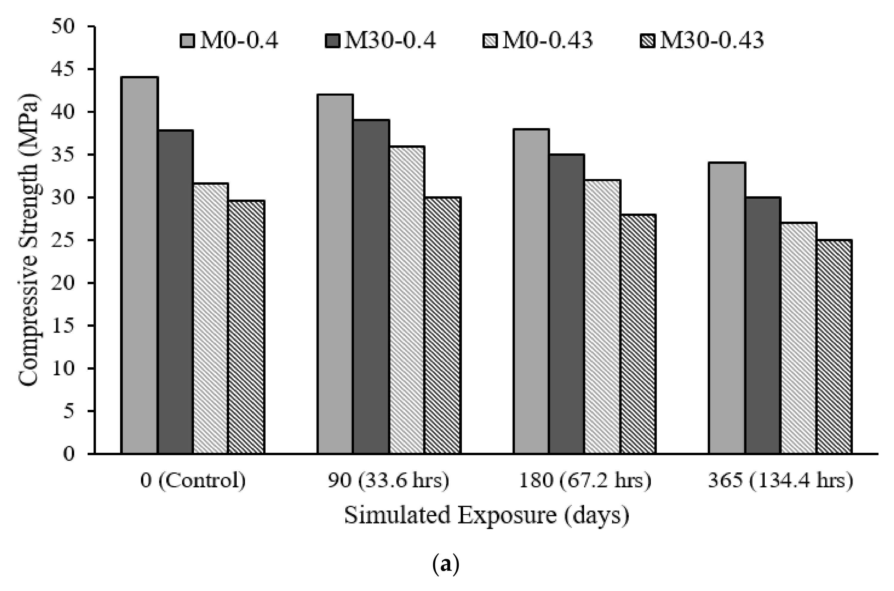
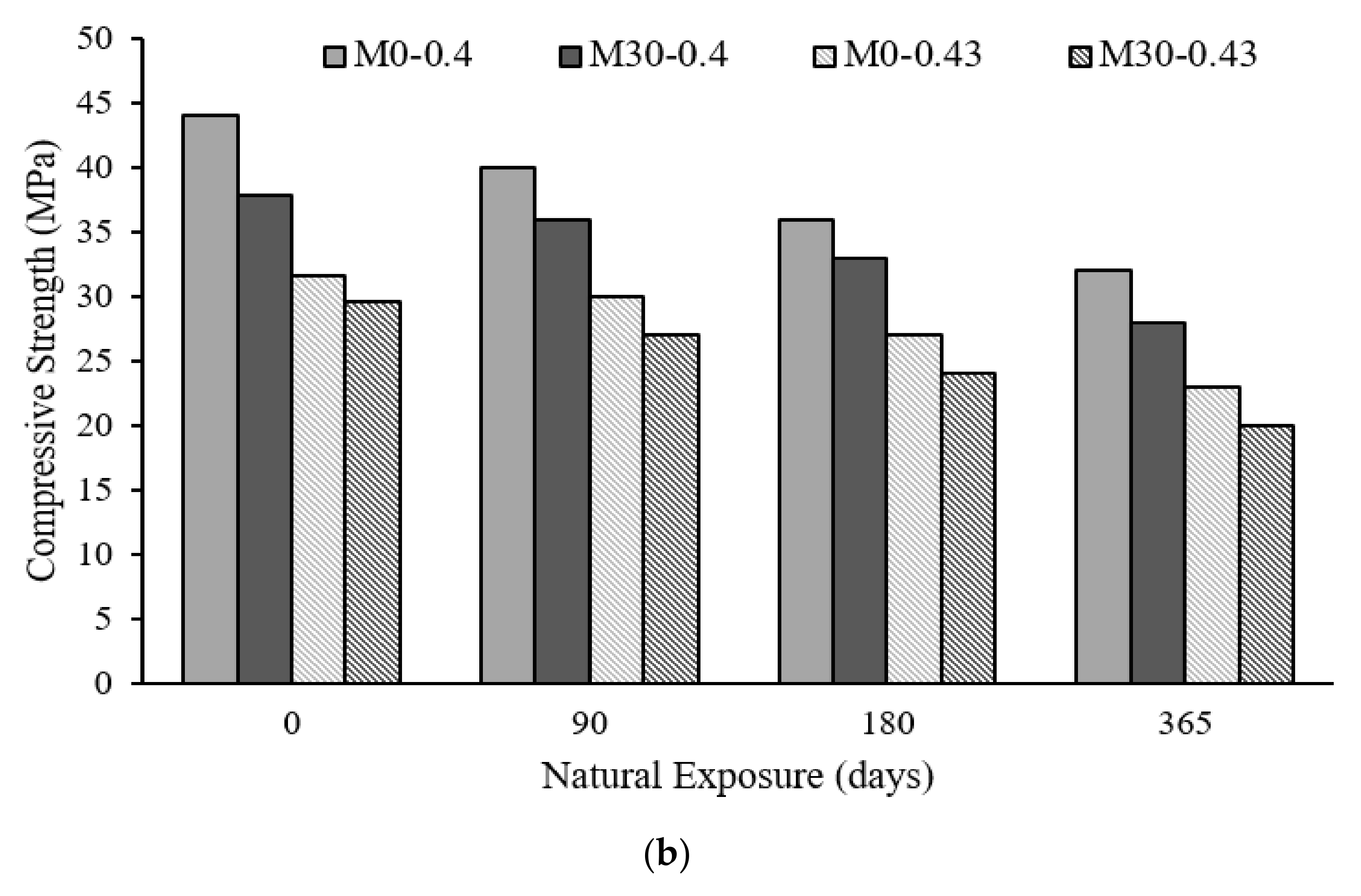
4.2.1. Compressive Strength

Three identical cylinders of 100 mm diameter and 200 mm in height, cast from concrete mixes M0-0.4, M30-0.4, M0-0.43 and M30-0.43 (refer to Table 3) and exposed to simulated and natural exposure to CO2 were tested for compressive strength of concrete as per the provisions of ASTM C39 [19]. The compression test was performed after equivalent exposure of cylinders in the carbonation chamber for 33.6, 67.2 and 134.4 h, which is equivalent to the exposure age of 90, 180 and 365 days [32]. Additionally, the compression test was performed for the cylinders kept in an open environment for a period of 90, 180 and 365 days. It was earlier mentioned that three cylinders were also tested at 28 days to compare the results of compressive strength before and after exposure to the natural and simulated environment. The results for the compressive strength for the simulated environment and natural environment are shown in Figure 8a,b.
From Figure 8a, it can be concluded that cylinders exposed to the simulated environment were found to have slightly higher compressive strength as compared to the one exposed in the natural environment. In general, the long exposure period affected the compressive strength. A similar observation is also reported by Ali et al. [34], who reported that the CaCO3 reduces the compressive strength of a matured concrete as compared to the one without CaCO3.
It is further observed that concrete with a 30% replacement percentage of NCA with RCA resulted in a reduced compressive strength as compared to the one containing 100% NCA. In a comparison of results, it can be reported that concrete with a higher water-cement ratio, i.e., concrete mix having a w/c ratio of 0.43, was found to have reduced compressive strength as compared to mix-0.4. The same trend of results was reported in the experimental study [36], which reported that the use of RCA reduces the compressive strength and that the strength reduction increases as the use of RCA increases.
The compressive strength of non-carbonated and carbonated cylinders prepared from mixes M0-0.4 and M30-0.4, exposed to the simulated environment was found to differ by 4.54%, 13.64% and 22.72% at 90, 180 and 365 days’ exposure, respectively. In the case of mixes M30-0.4, M0-0.43 and M30-0.43, the compressive strength of carbonated concrete reduced up to 20%, 14.56% and 15.54% at an exposure equivalent to 365 days in the simulated environment.
The reduction in the compressive strength of concrete mixes M0-0.4, M30-0.4, M0-0.43 and M30-0.43 exposed to the natural environment was found to be as high as 27.3%, 26%, 27.22% and 32.43% at 365 days. It is noteworthy that the lowest compressive strength and maximum reduction in the compressive strength as compared to an unexposed concrete was observed in mix M30-0.43. The reason can be associated with the use of RCA and higher w/c ratio as mentioned in [37] that numerous factors impact the compressive strength of concrete containing RCA concrete, including the w/c ratio, which has an inverse relationship with the compressive strength of concrete containing RCA. Moreover, as previously mentioned, the use of RCA reduces compressive strength [36].
Comparing the results of the mixes exposed to the simulated and natural environments, it was observed that the compressive strength of carbonated cylinders exposed to the natural environment is slightly lower than those exposed to the simulated environment. The microstructure of the concrete is exposed to the natural environment and contains RCA-evident pores, CaCO3 precipitation, which causes the lowering of pH of concrete and disintegration of concrete (refer to Figure 4 and Figure 5). The maximum compressive strength variation prepared from mixes M0-0.4, M30-0.43, M0-0.43 and M30-0.43 was differed by 5.88%, 7.69%, 16.67 and 20% for an exposure period up to 365 days. The results analysis showed that the carbonation resistance of concrete containing RCA was significantly reduced at later ages. The reduction in the compressive strength at later ages was also reported by Ali et al. [34]. This might be due to the variation in RH, temperature and CO2 concentration in the natural environment, which led to the variation in the results.

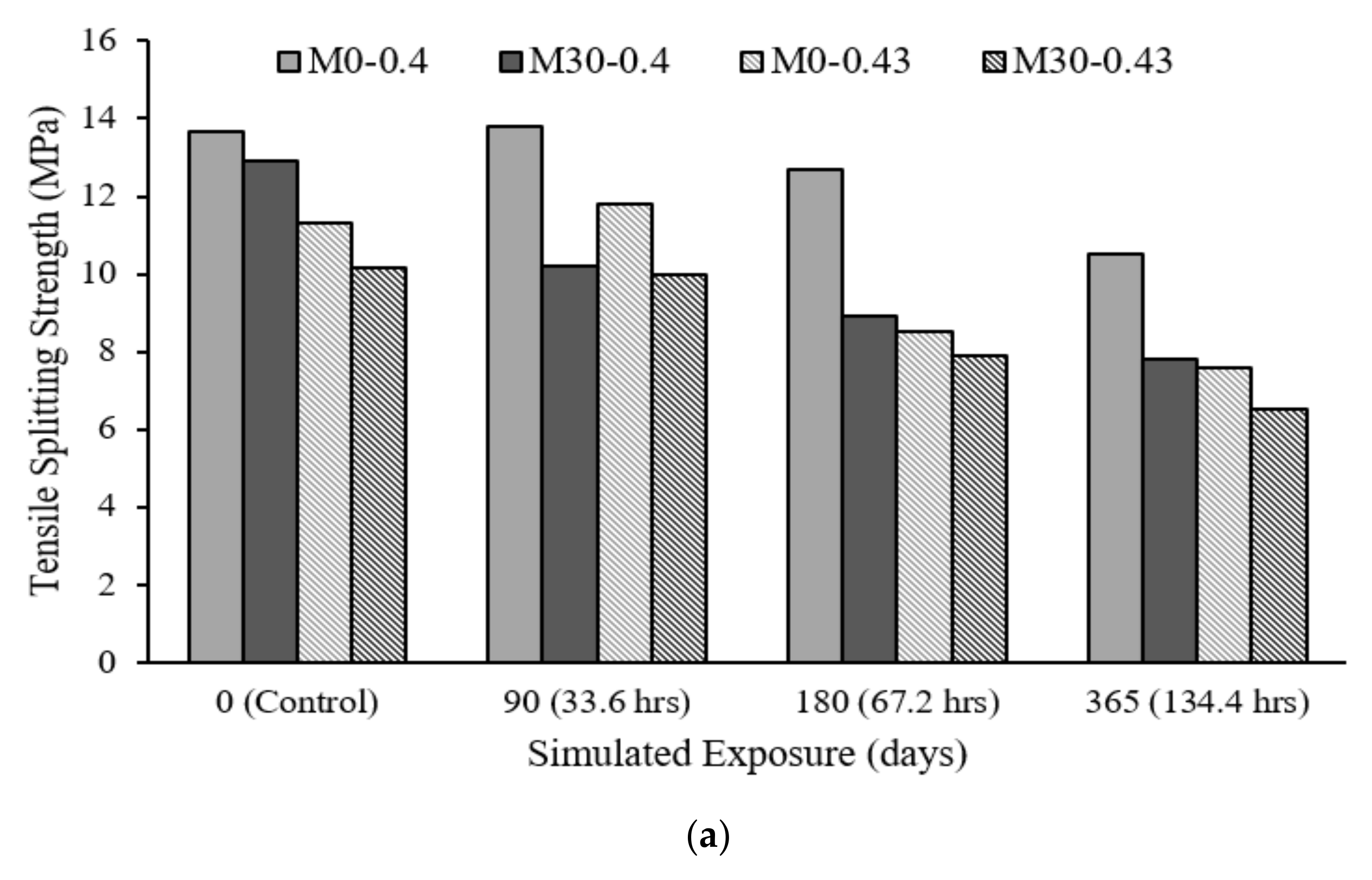
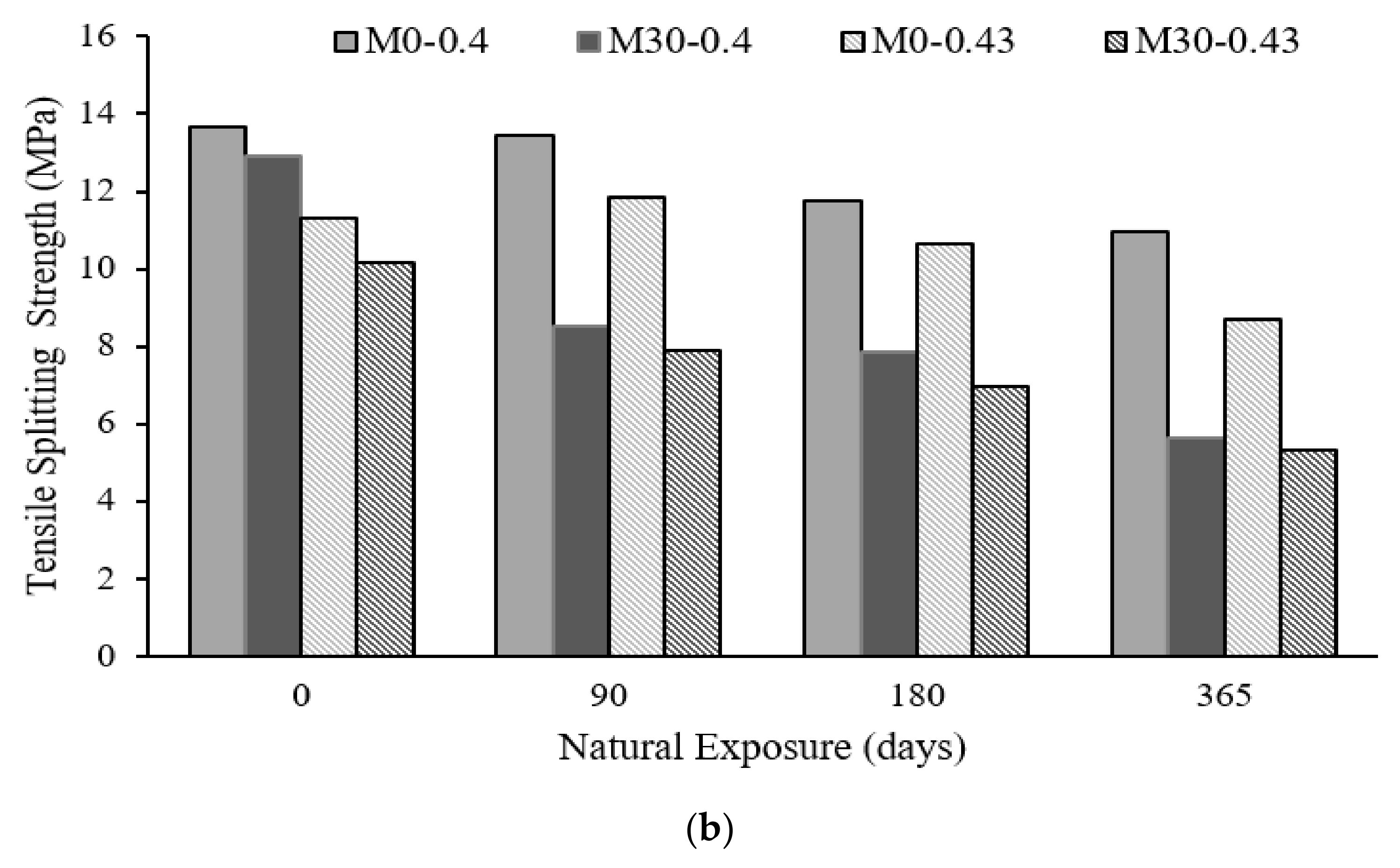
4.2.2. Splitting Tensile Strength

The concrete cylinders of each batch of mix prepared using w/c ratio of 0.4 and 0.43 were tested for splitting tensile strength as per ASTM C496/496M procedure [20] after the exposure to carbonation in both simulated and natural environments. The results for concrete cylinders exposed to the simulated and natural environment for both batches of concrete are shown in Figure 9a,b. From the following figures, it can be observed that the splitting tensile strength in concrete decreases as the exposure duration increases which is due to the presence of RCA in the concrete batch. Also, mixes M0-0.4 and M0-0.43 exhibited higher splitting tensile strengths as compared to mixes M30-0.4 and M30-0.43 at all ages of carbonation exposure due to the presence of natural coarse aggregates.
The reduction in the splitting tensile strength of concrete mixes M0-0.4, M30-0.4, M0-0.43 and M30-0.43 exposed to the natural environment was found to be as high as 23.13%, 39%, 32.7% and 36% at 365 days. It is to note that the lowest splitting tensile strength and maximum reduction in the splitting tensile strength as compared to an unexposed concrete was observed in mix M30-0.43. The reason can be associated with the use of RCA and higher w/c ratio as mentioned in [37].
Similarly, mixes M0-0.4 and M30-0.4 resulted in higher splitting tensile strength as compared to mixes M0-0.43 and M30-0.43 due to the reduced w/c ratio. The cylinders exposed to the natural environment possess reduced splitting tensile strength as compared to the simulated environment. The reason might be the presence of a higher CO2 percentage concentration, RH and temperature in the natural environment.
The results of splitting tensile strength tests of cylinders cast from w/c ratio of 0.4 and 0.43 exposed to both natural and simulated environments were analyzed. It has been found that for the mix cast by using w/c ratio of 0.4, the results of splitting tensile strength of cylinders prepared from mixes M0-0.4, M30-0.4, M0-0.43 and M30-0.43 exposed to natural environment differ by 7.4%, 27.6%, 25.41% and 18.2% up to 365 days of exposure, respectively, as compared to the simulated environment.

5. Conclusions

The carbonation resistance of concrete is highly influenced by environmental exposure conditions such as temperature, humidity and CO2 concentration. In a highly aggressive environment, the w/c ratio may enhance the effect of carbonation in concrete due to higher porosity. From this experimental study, the influence of w/c ratio, replacement percentage of NCA with RCA and environmental exposure conditions on the microstructure, carbonation depth, compressive and splitting tensile strength was analyzed, which can be concluded as:
  • The microstructure examination of the mixes containing natural coarse aggregates (i.e., M0-0.4) is less porous than those containing 30% RCA. Overall, the microstructure of concrete exposed to a natural environment contained visible pores and cracks in comparison with the simulated environment. Concrete mix can be visualized at the micro-level for the mixes prepared using a w/c ratio of 0.4 and 0.43. The non-carbonated concrete does not contain any visible cracks and pores, whereas, the ITZ of aggregate seems to be changed in the carbonated samples, which indicates that the penetration of CO2 influences the ITZ of NCA and RCA.
  • The use of a higher w/c ratio reduced the carbonation resistance by increasing the porosity of concrete. The water-cement ratio increases; it influences the porosity of concrete, which results in reduced resistance for carbonation. A lower carbonation depth was observed in the mix that was produced using less w/c ratio of 0.4 and contained NCA (i.e., Mix M0-0.4), whereas the highest carbonation depth was observed in the mix cast using w/c of 0.43 and recycled concrete aggregates (i.e., Mix M30-0.43).
  • Concrete containing 30% RCA resulted in a reduced compressive strength as compared to the one containing 100% NCA. In a comparison of results, it can be reported that concrete with a higher water-cement ratio, i.e., the concrete mix having a w/c ratio of 0.43 was found to be more carbonated, with reduced compressive strength as compared to mix-0.4. The compressive strength of non-carbonated and carbonated cylinders prepared from mixes M0-0.4 and M30-0.4, exposed to the simulated environment, was found to differ by 4.54%, 13.64% and 22.72% at 90, 180 and 365 days exposure, respectively. In the case of mixes M30-0.4, M0-0.43 and M30-0.43, the compressive strength of carbonated concrete reduced up to 20%, 14.56% and 15.54% at an exposure equivalent to 365 days in the simulated environment. The reduction in the compressive strength of concrete mixes M0-0.4, M30-0.4, M0-0.43 and M30-0.43 exposed to the natural environment was found to be as maximum as 27.3%, 26%, 27.22% and 32.43% at 365 days.
  • The reduction in the splitting tensile strength of concrete mixes M0-0.4, M30-0.4, M0-0.43 and M30-0.43 exposed to the natural environment was found to be as high as 23.13%, 39%, 32.7% and 36% at 365 days. It is noteworthy that the lowest splitting tensile strength and maximum reduction in the splitting tensile strength as compared to an unexposed concrete was observed in mix M30-0.43. due to the use of RCA and higher w/c ratio.

Author Contributions

Conceptualization, W.M. and T.A.; Data curation, W.M.; Formal analysis, W.M. and T.A.; Funding acquisition, T.A. and A.-u.-R.K.; Investigation, W.M.; Methodology, W.M. and T.A.; Supervision, T.A. and A.-u.-R.K.; Validation, W.M. and T.A.; Writing—original draft, W.M. and T.A.; Writing—review & editing, T.A., A.-u.-R.K. and W.M. All authors have read and agreed to the published version of the manuscript.

Funding

This research received no external funding.

Institutional Review Board Statement

Not applicable.

Informed Consent Statement

Not applicable.

Data Availability Statement

The data presented in this study are available on request from the corresponding author.

Acknowledgments

All those who supported the smooth conductance of experimental work.

Conflicts of Interest

The authors declare no conflict of interest.

References

  1. Al Nuaimi, N.; Sohail, M.G.; Hawileh, R.; Abdalla, J.A.; Douier, K. Durability of Reinforced Concrete Beams Externally Strengthened with CFRP Laminates under Harsh Climatic Conditions. J. Compos. Constr. 2021, 25, 04021005. [Google Scholar] [CrossRef]
  2. Varlamov, A.; Rimshin, V.; Davydov, A.; Minnatov, A.R.; Kurbatov, A.M. Research of the Degradation Process of Reinforced Concrete Structures. IOP Conf. Series Mater. Sci. Eng. 2021, 1079, 062005. [Google Scholar] [CrossRef]
  3. Meng, D.; Wu, X.; Quan, H.; Zhu, C. A strength-based mix design method for recycled aggregate concrete and consequent durability performance. Constr. Build. Mater. 2021, 281, 122616. [Google Scholar] [CrossRef]
  4. Dehvari, A.G.; Miri, M.; Sohrabi, M.R. Reliability-Based Design Optimization of Recycled Coarse Aggregates Used in Corrosive Environment. J. Mater. Civ. Eng. 2021, 33, 04021042. [Google Scholar] [CrossRef]
  5. Padmini, A.; Ramamurthy, K.; Mathews, M. Influence of parent concrete on the properties of recycled aggregate concrete. Constr. Build. Mater. 2009, 23, 829–836. [Google Scholar] [CrossRef]
  6. Xiao, J.; Lei, B.; Zhang, C. On carbonation behavior of recycled aggregate concrete. Sci. China Ser. E Technol. Sci. 2012, 55, 2609–2616. [Google Scholar] [CrossRef]
  7. Neville, A.M.; Brooks, J.J. Concrete Technology, 2nd ed.; Pearson: London, UK, 2010. [Google Scholar]
  8. Neves, R.; Branco, F.; de Brito, J. A method for the use of accelerated carbonation tests in durability design. Constr. Build. Mater. 2012, 36, 585–591. [Google Scholar] [CrossRef]
  9. Silva, A.; Neves, R.; de Brito, J. Statistical modelling of carbonation in reinforced concrete. Cem. Concr. Compos. 2014, 50, 73–81. [Google Scholar] [CrossRef]
  10. Hussain, R.R.; Ishida, T. Development of numerical model for FEM computation of oxygen transport through porous media coupled with micro-cell corrosion model of steel in concrete structures. Comput. Struct. 2010, 88, 639–647. [Google Scholar] [CrossRef]
  11. Zanini, M.A.; Faleschini, F.; Pellegrino, C. Probabilistic seismic risk forecasting of aging bridge networks. Eng. Struct. 2017, 136, 219–232. [Google Scholar] [CrossRef]
  12. Peter, M.; Muntean, A.; Meier, S.; Böhm, M. Competition of several carbonation reactions in concrete: A parametric study. Cem. Concr. Res. 2008, 38, 1385–1393. [Google Scholar] [CrossRef] [Green Version]
  13. Lee, J.-C.; Song, T.-H.; Lee, S.-H. Leaching behavior of toxic chemicals in recycled aggregates and their alkalinity. J. Mater. Cycles Waste Manag. 2012, 14, 193–201. [Google Scholar] [CrossRef]
  14. Fung, W. Durability of concrete using recycled aggregates. Presented at the SCCT Annual Concrete Seminar, Hong Kong, 3 February 2005. [Google Scholar]
  15. Silva, R.; Neves, R.; de Brito, J.; Dhir, R. Carbonation behaviour of recycled aggregate concrete. Cem. Concr. Compos. 2015, 62, 22–32. [Google Scholar] [CrossRef] [Green Version]
  16. Otsuki, N.; Miyazato, S.-I.; Yodsudjai, W. Influence of Recycled Aggregate on Interfacial Transition Zone, Strength, Chloride Penetration and Carbonation of Concrete. J. Mater. Civ. Eng. 2003, 15, 443–451. [Google Scholar] [CrossRef]
  17. Ryu, J. An experimental study on the effect of recycled aggregate on concrete properties. Mag. Concr. Res. 2002, 54, 7–12. [Google Scholar] [CrossRef]
  18. Levy, S.M.; Helene, P. Durability of recycled aggregates concrete: A safe way to sustainable development. Cem. Concr. Res. 2004, 34, 1975–1980. [Google Scholar] [CrossRef]
  19. Lovato, P.S.; Possan, E.; Molin, D.C.C.D.; Masuero, B.; Ribeiro, J.L. Modeling of mechanical properties and durability of recycled aggregate concretes. Constr. Build. Mater. 2012, 26, 437–447. [Google Scholar] [CrossRef]
  20. Kou, S.-C.; Poon, C.S. Long-term mechanical and durability properties of recycled aggregate concrete prepared with the incorporation of fly ash. Cem. Concr. Compos. 2013, 37, 12–19. [Google Scholar] [CrossRef]
  21. Ogundipe, O.M.; Olanike, A.O.; Nnochiri, E.S.; Ale, P.O. Effects of coarse aggregate size on the compressive strength of concrete. Civ. Eng. J. 2018, 4, 836–842. [Google Scholar] [CrossRef] [Green Version]
  22. ASTM. Standard Test Method for Relative Density (Specific Gravity) and Absorption of Coarse Aggregate; ASTM International: West Conshohocken, PA, USA, 2015. [Google Scholar]
  23. BS 812-110:1990. Testing Aggregates—Part 110: Methods for Determination of Aggregate Crushing Value (ACV); British Standards Institution: London, UK, 1990. [Google Scholar]
  24. ASTM C131/C131M—20. Standard Test Method for Resistance to Degradation of Small-Size Coarse Aggregate by Abrasion and Impact in the Los Angeles Machine; ASTM International: West Conshohocken, PA, USA, 2020. [Google Scholar]
  25. Xiao, J. Recycled Aggregate Concrete Structures; Springer: Berlin/Heidelberg, Germany, 2018; pp. 65–98. [Google Scholar]
  26. Designation, A. C192/C192M-18. Standard Practice for Making and Curing Concrete Test Specimens in the Laboratory; ASTM International: West Conshohocken, PA, USA, 2018. [Google Scholar]
  27. ASTM. Cement; ASTM C 150/C 150M. Type I. 1; ASTM International: West Conshohocken, PA, USA, 2021. [Google Scholar]
  28. Khan, A.-U.; Khan, M.S.; Fareed, S.; Xiao, J. Structural Behaviour and Strength Prediction of Recycled Aggregate Concrete Beams. Arab. J. Sci. Eng. 2019, 45, 3611–3622. [Google Scholar] [CrossRef]
  29. ASTM. C39/C39M-18. Standard Test Method for Compressive Strength of Concrete; ASTM International: West Conshohocken, PA, USA, 2020. [Google Scholar]
  30. ASTM. C496/C496M-17. Standard Test Method for Splitting Tensile Strength of Cylindrical Concrete Specimens; ASTM International: West Conshohocken, PA, USA, 2020. [Google Scholar]
  31. Leemann, A.; Loser, R. Carbonation resistance of recycled aggregate concrete. Constr. Build. Mater. 2019, 204, 335–341. [Google Scholar] [CrossRef]
  32. Jones, M.; Dhir, R.K.; Newlands, M.D.; Abbas, A.M.O. A study of the CEN test method for measurement of the carbonation depth of hardened concrete. Mater. Struct. 2000, 33, 135–142. [Google Scholar] [CrossRef]
  33. Rao, M.C.; Bhattacharyya, S.K.; Barai, S.V. Microstructure of recycled aggregate concrete. In Systematic Approach of Characterisation and Behaviour of Recycled Aggregate Concrete; Springer: Singapore, 2019; pp. 209–247. [Google Scholar]
  34. Ali, M.; Abdullah, M.S.; Saad, S.A. Effect of Calcium Carbonate Replacement on Workability and Mechanical Strength of Portland Cement Concrete. Adv. Mater. Res. 2015, 1115, 137–141. [Google Scholar] [CrossRef]
  35. Kim, J.-K.; Kim, C.-Y.; Yi, S.-T.; Lee, Y. Effect of carbonation on the rebound number and compressive strength of concrete. Cem. Concr. Compos. 2009, 31, 139–144. [Google Scholar] [CrossRef]
  36. Uche, O. Influence of recycled concrete aggregate (RCA) on compressive strength of plain concrete. Cont. J. Eng. Sci. 2008, 3, 30–38. [Google Scholar]
  37. McNeil, K.; Kang, T.H.-K. Recycled concrete aggregates: A review. Int. J. Concr. Struct. Mater. 2013, 7, 61–69. [Google Scholar] [CrossRef] [Green Version]
Figure 1. Crushed RCA (on left) and Jaw Crusher (on right).
Sustainability 14 00437 g001
Figure 2. (a) Thermohygrometer (b) Carbon dioxide meter.
Sustainability 14 00437 g002
Figure 3. (a) Cylinders exposure to the natural environment area at Department of Civil Engineering, NEDUET (b) Cylinders placed in carbonation chamber for the simulated test.
Sustainability 14 00437 g003
Figure 4. Microstructure of non-carbonated and carbonated concrete mix containing w/c-0.4 and exposed to the simulated and natural environment (a) M0-0.40 (Non-carbonated cylinder) (b) M30-0.40 (Non-carbonated cylinder) (c) M0-0.4 (exposed to the simulated environment) (d) M30-0.4 (exposed to the simulated environment) (e) M30-0.4 (exposed to the natural environment) (f) M0-0.4 (exposed to the natural environment).
Sustainability 14 00437 g004
Figure 5. Microstructure of non-carbonated and carbonated concrete mix containing w/c-0.43 and exposed to the simulated and natural environment. (a) M0-0.43 (Non-carbonated cylinder) (b) M30-0.43 (Non-carbonated cylinder) (c) M0-0.43 (exposed to simulated environment) (d) M30-0.43 (exposed to simulated environment) (e) M0-0.43 (exposed to the natural environment) (f) M30-0.43 (exposed to the natural environment).
Sustainability 14 00437 g005
Figure 6. (a) Experimental setup to split the cylinder of concrete mixes to measure carbonation depth (b) Procedure of measurement of carbonation depth on the concrete cylinders (typical) (c) Carbonated region for the cylinder exposed to the simulated environment (d) Carbonated region for the cylinder exposed to the natural environment exposure.
Sustainability 14 00437 g006
Figure 7. Carbonation depth results measured on the bifurcated cylinders with and without RCA exposed to (a) simulated environment (b) natural environment.
Sustainability 14 00437 g007aSustainability 14 00437 g007b
Figure 8. Compressive strength results with and without RCA exposed to (a) simulated environment (b) natural environment.
Sustainability 14 00437 g008aSustainability 14 00437 g008b
Figure 9. Splitting tensile strength results with and without RCA exposed to (a) simulated environment (b) natural environment.
Sustainability 14 00437 g009aSustainability 14 00437 g009b
Table 1. Physical Properties of RCA.
Physical PropertiesTest ResultsStandard Range
Specific Gravity SSD (gm/cm3)2.432.5–3 [22]
Crushing Value (%)47.82<30 [23,24]
Water Absorption (%)4.50.1–2 [22]
Impact Value (%)39.97<45 [24]
Table 2. Mix proportion for concrete mix-0.4 with and without RCA.
MixAggregate Replacement Percentage (%)w/c RatioCement (kg/m3)Fine (kg/m3)NCA (kg/m3)RCA (kg/m3)Water (kg/m3)Superplasticizer (%)
M0-0.400.40454.01567.511183.260181.61.6
M30-0.4300.40454.01536.34782.79335.48181.61.5
M0-0.4300.43454.01567.511183.260195.221.6
M30-0.43300.43454.01536.34782.79335.48195.221.5
Table 3. Sample details for simulated and natural exposure testing.
Exposure TypeExperimental TestsCylinder SizeNo. of Cylinder(s)Remarks
w/c = 0.40w/c = 0.43
M0-0.4M30-0.4M0-0.43M0-0.43
UnexposedCompressive Strength100 mm dia. × 200 mm height03030303Three out of nine cylinders were exposed to the simulated environment in a carbonation chamber for an equivalent 90, 180 and 365 days of exposure, whereas three out of nine cylinders were kept for natural exposures to study the effect of carbonation based on exposure type and to compare with and without CO2 exposure
Split Tensile Strength and Carbonation Depth100 mm dia. × 200 mm height03030303
SimulatedCompressive Strength100 mm dia. × 200 mm height09090909
Split Tensile Strength and Carbonation Depth100 mm dia. × 200 mm height09090909
NaturalCompressive Strength100 mm dia. × 200 mm height09090909
Split Tensile Strength and Carbonation Depth100 mm dia. × 200 mm height09090909
Note: Three cylinders from each mix were dedicated for an exposure period of 90, 180 and 365 days.
Table 4. Natural environment curing conditions.
Month-YearConcentration of Carbon Dioxide (ppm)Humidity (%)Temperature (°C)
February-2020433.13429.7
March-202041036.530
April-2020483.753.632.3
May-2020434.256233.5
June-2020455.665.534.6
July-2020458.868.235.2
August-2020466.6774.3230.7
September-2020432.568.1131.2
October-2020467.7863.5634
November-2020433.553.224.5
December-2020472.455.619.5
January-202148145.921
Publisher’s Note: MDPI stays neutral with regard to jurisdictional claims in published maps and institutional affiliations.

