
Analysis of EMG Electrode Locations Using 3D Body Scanning for Digital Pattern Construction of a Smart EMG Suit


Abstract
:1. Introduction
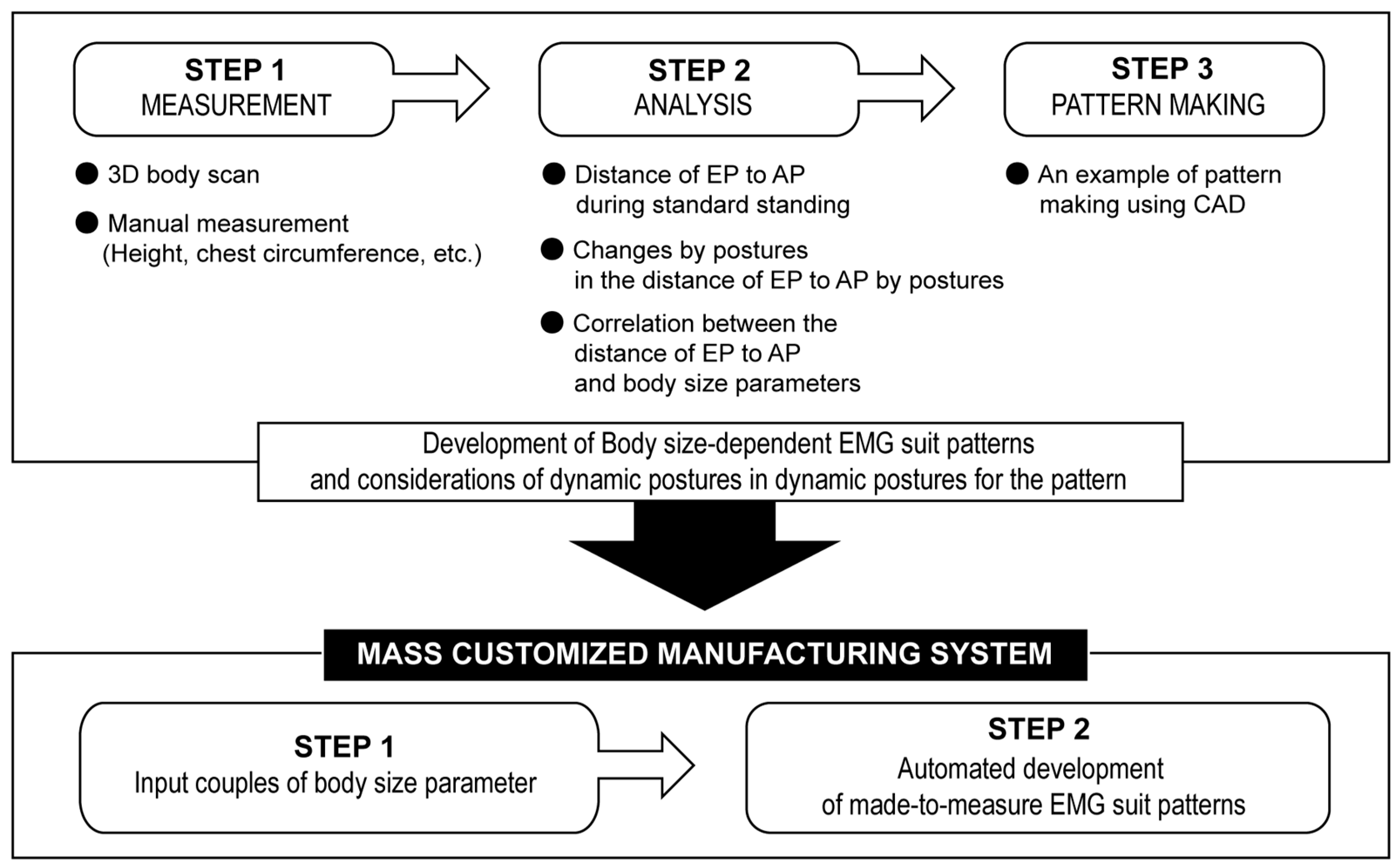
2. Methods
2.1. Subjects
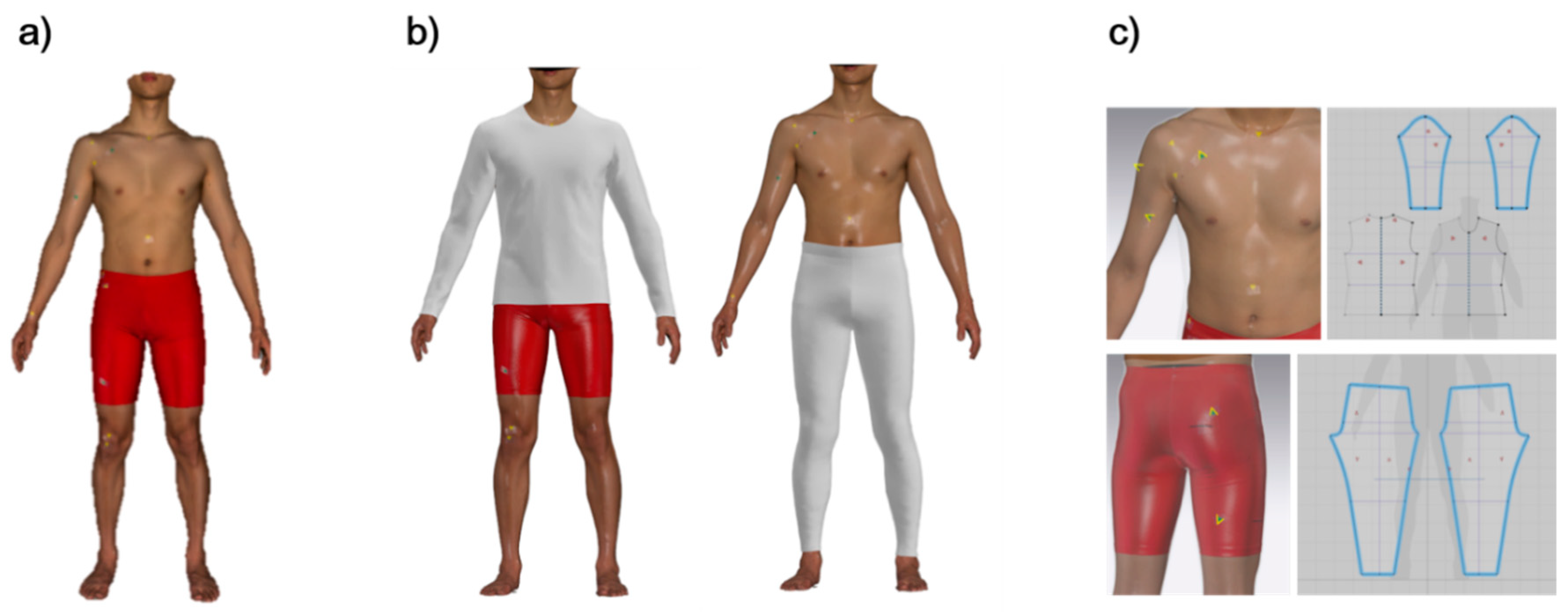
2.2. 3D Body Scanning Protocol
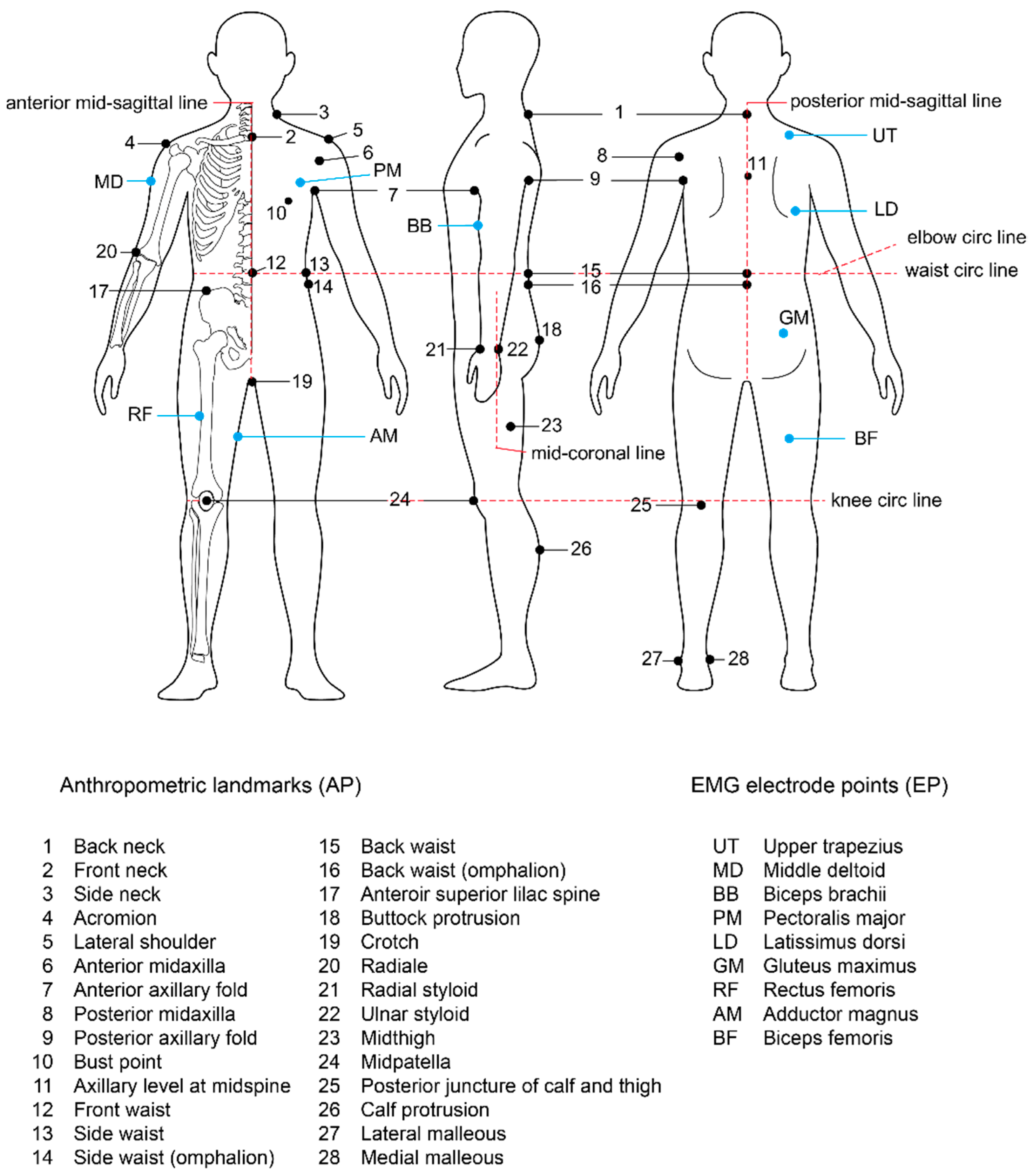
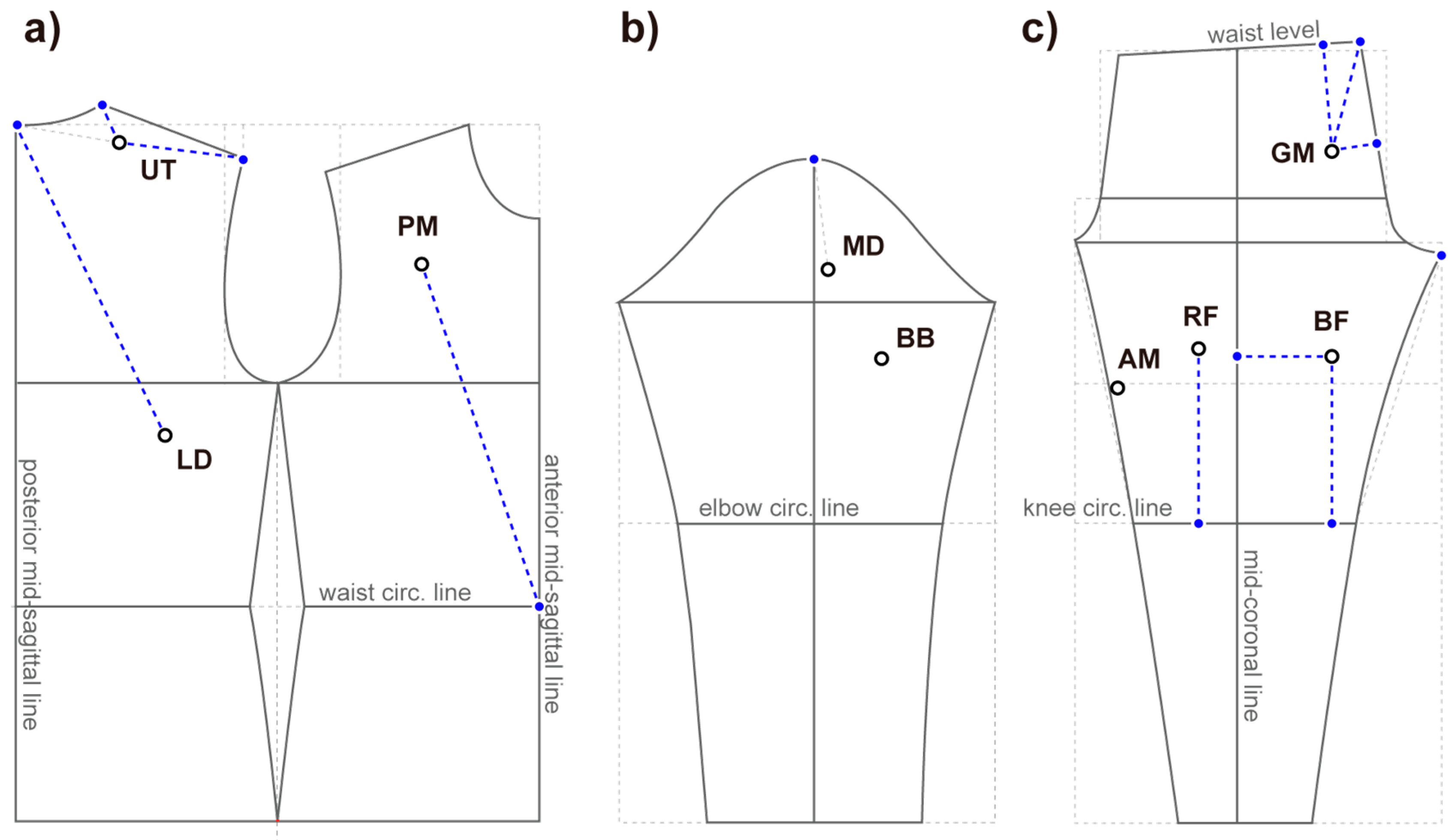
2.3. Landmarks: Anthropometric Points (AP) and EMG Electrode Attachment Points (EP)
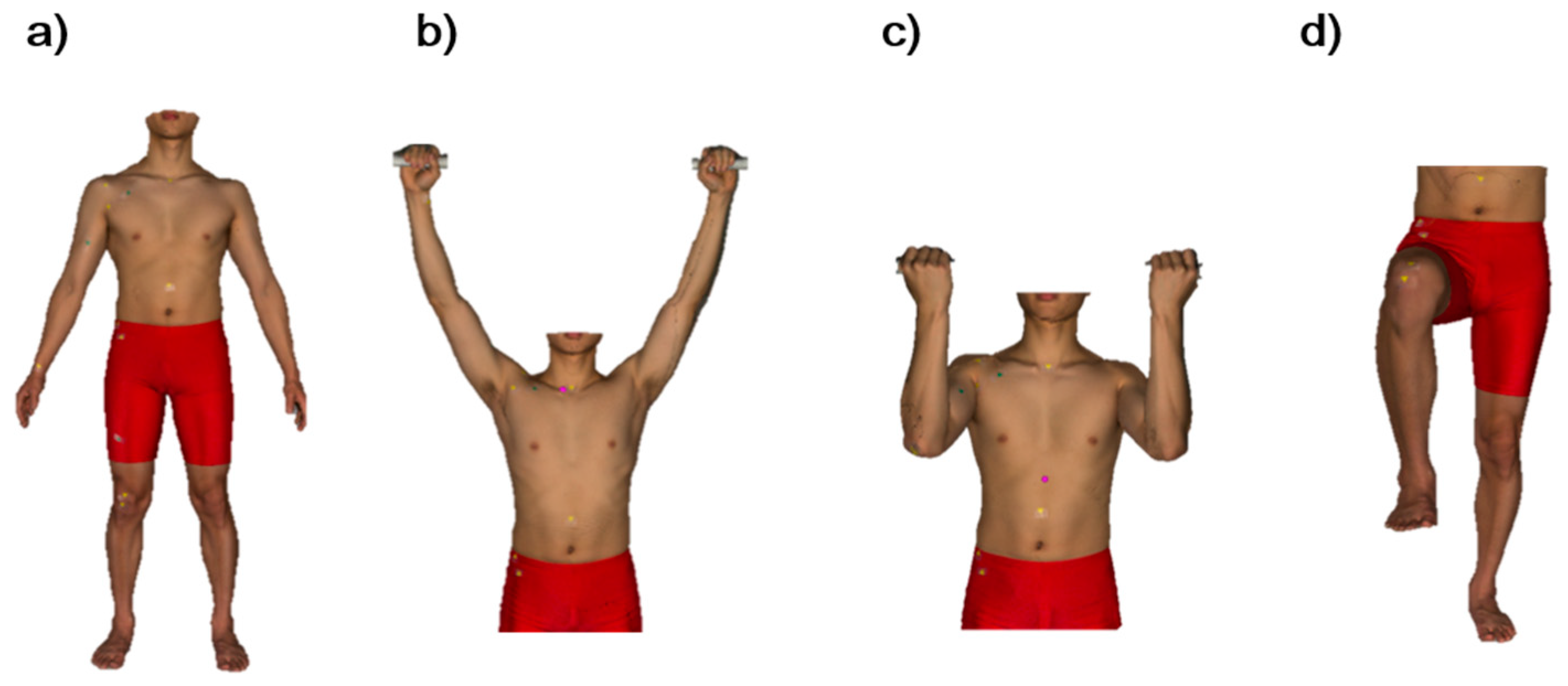
2.4. 3D Body Scan Postures
2.5. Manual Measurement for the Body Size Parameters
2.6. Data Analysis
2.7. Pattern Making
3. Results
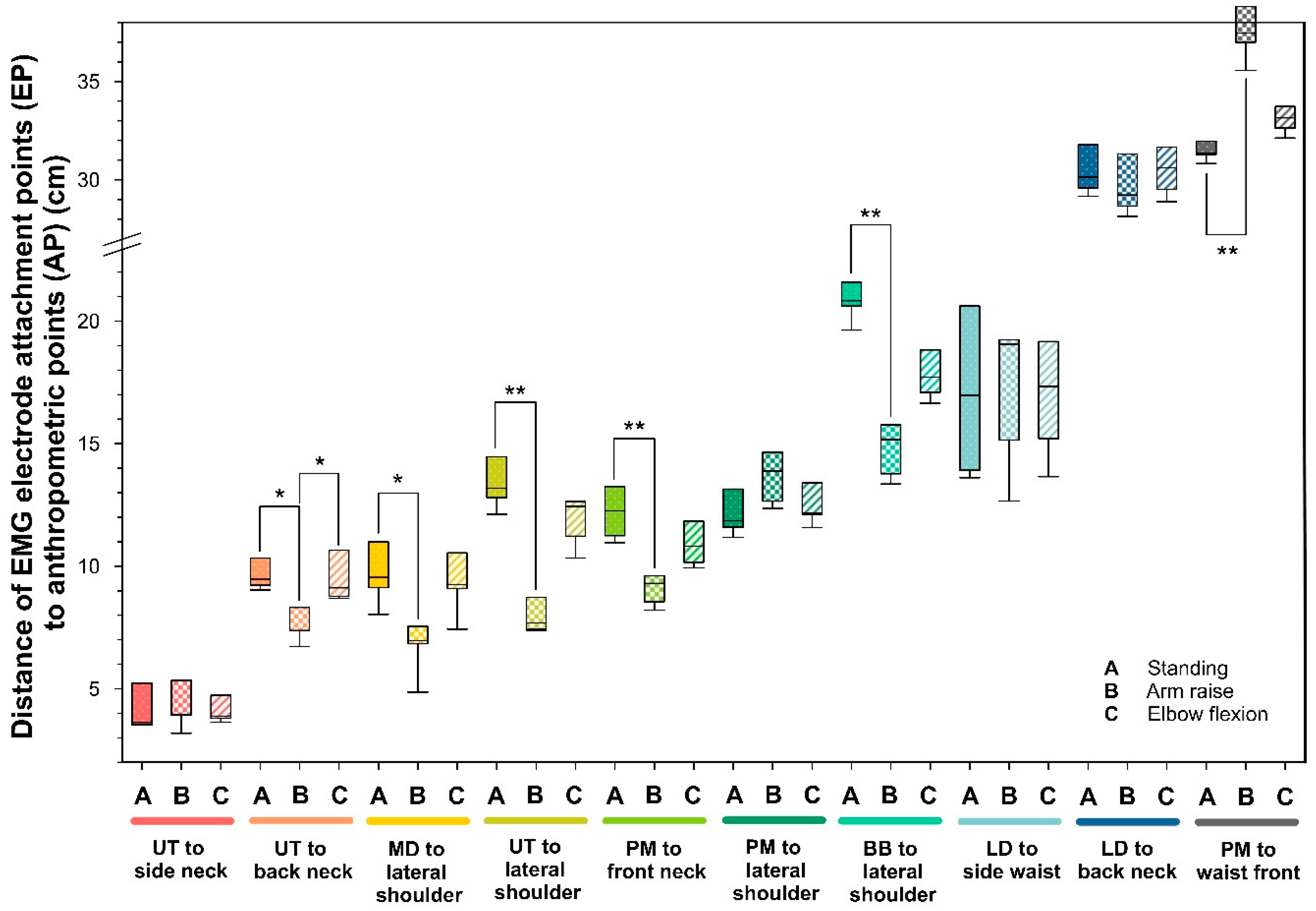
3.1. Distance from AP to EP in a Standard Standing Posture and Changes by Dynamic Postures
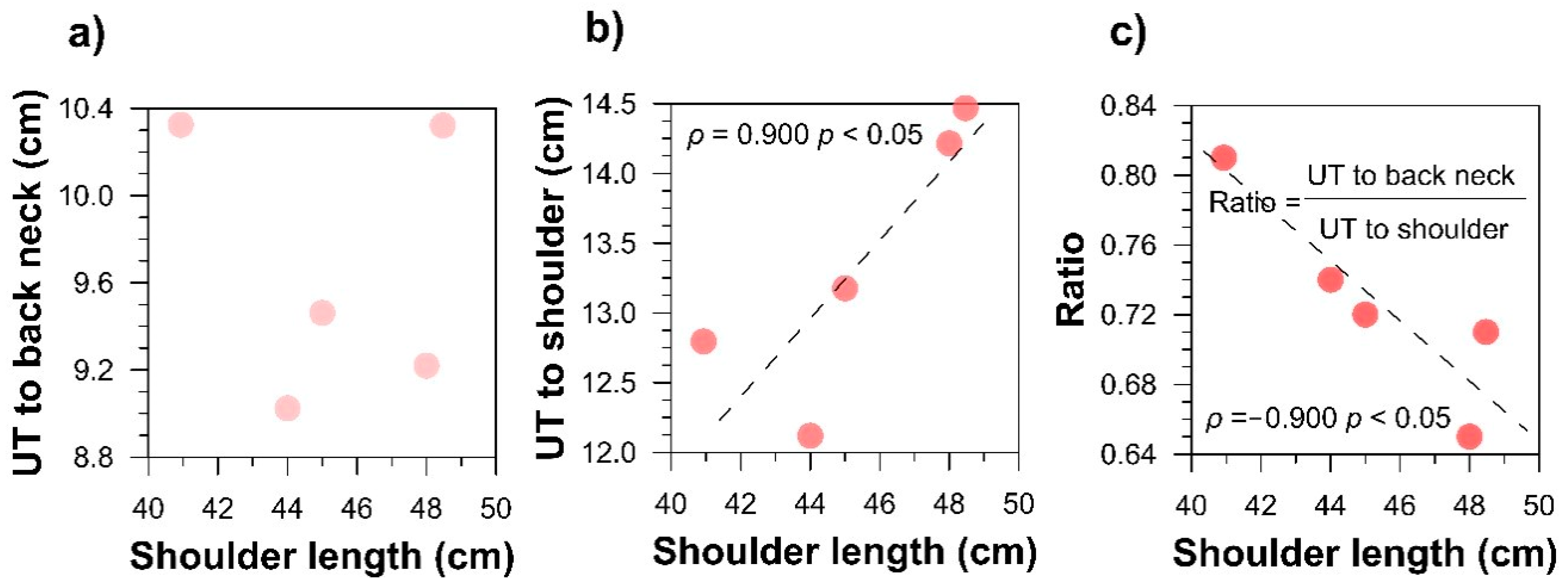
3.2. Relationship between EP and Body Size Parameters
3.3. Specifying the EMG Electrodes’ Location on Clothing Pattern
4. Discussion
4.1. Overview of the Results
4.2. Pattern Development including the EMG Electrodes
4.3. Movement of the Location of EPs by Postures
5. Conclusions
- (a)
- Locations of EPs in the upper body are less stable against the dynamic body postures than those of the lower body. In particular, the arm raise postures significantly decreased the distance between UT to the back neck and lateral shoulder, which makes UT vulnerable to the dynamic body postures. Any wrinkles of the fabric can generate more noise in EMG signals.
- (b)
- A consistency between recommended EMG electrode locations for the high EMG signal yield and morphologically appropriate electrode locations may be not easily found. For instance, the electrode of UT is better to be placed 2 cm lateral to the midpoint between the processus prominens (back neck point) and acromion. However, that region may not be appropriate in a perspective of stability of electrode–skin surface contact. Follow-up studies should seek a sound compromise between them.
- (c)
- According to the correlation between the body size parameters and distance of EP and AP, it is considered that the height can be the most useful independent variable to estimate the electrode locations of various muscles: UT, PM, GM, AM, and BF. When considering that a size-dependent design strategy is essential for producing made-to-measure clothing in a mass customization system, the variables which showed significant correlations with distance of EP to AP should be revisited to develop substantive equations that can be used in pattern design.
- (d)
- At last, an example of a clothing pattern, including the EMG electrode location, was suggested in this study, based on basic patterns because the basic pattern can be applied in various clothing patterns through a transformation. Potent anthropometric variables and valid issues were noted. However, to realize a completion of clothing pattern design for smart EMG suits, lines that showed a significant correlation with the body size parameters in Table 2 should be revisited soon to develop substantive equations.
Author Contributions
Funding
Institutional Review Board Statement
Informed Consent Statement
Data Availability Statement
Conflicts of Interest
Abbreviations
| AM | Adductor magnus |
| AP | Anthropometric points (landmarks) |
| BB | Biceps brachii |
| BF | Biceps femoris |
| CAD | Computer-aided design |
| ECG | Electrocardiogram |
| EMG | Electromyography |
| EP | EMG electrode attachment points |
| GM | Gluteus maximus |
| ICT | Information and communication technology |
| IoT | Internet of things |
| LD | Latissimus dorsi |
| MD | Middle deltoid |
| PM | Pectoralis major |
| RF | Rectus femoris |
| UT | Upper trapezius |
References
- Ahsan, M.; Hon, S.T.; Albarbar, A. Development of novel big data analytics framework for smart clothing. IEEE Access 2020, 8, 146376–146394. [Google Scholar] [CrossRef]
- Acar, G.; Ozturk, O.; Golparvar, A.J.; Elboshra, T.A.; Bohringer, K.; Yapici, M.K. Wearable and flexible textile electrodes for biopotential signal monitoring: A review. Electronics 2020, 8, 479. [Google Scholar] [CrossRef] [Green Version]
- Catherwood, P.A.; Donnelly, N.; Anderson, J.; McLaughlin, J. ECG motion artefact reduction improvements of a chest-based wireless patient monitoring system. In Proceedings of the 2010 Computing in Cardiology, Belfast, UK, 26–29 September 2010; Volume 37, pp. 557–560. [Google Scholar]
- Hug, F.; Dorel, S. Electromyographic analysis of pedaling: A review. J. Electromyogr. Kinesiol. 2009, 19, 182–198. [Google Scholar] [CrossRef] [PubMed]
- Lynn, S.K.; Watkins, C.M.; Wong, M.A.; Balfany, K.; Feeney, D.F. Validity and reliability of surface electromyography measurements from a wearable athlete performance system. J. Sports Sci. Med. 2018, 17, 205–215. [Google Scholar] [PubMed]
- Colyer, S.L.; McGuigan, P.M. Textile electrodes embedded in clothing: A practical alternative to traditional surface electromyography when assessing muscle excitation during functional movements. J. Sports Sci. Med. 2018, 17, 101–109. [Google Scholar]
- Finni, T.; Hu, M.; Kettunen, P.; Vilavno, T.; Cheng, S. Measurement of EMG activity with textile electrodes embedded into clothing. Physiol. Meas. 2020, 28, 1405–1419. [Google Scholar] [CrossRef] [PubMed]
- Winter, D.A.; Fuglevand, A.J.; Archer, S.E. Crosstalk in surface electromyography: Theoretical and practical estimates. J. Electromyogr. Kinesiol. 1994, 4, 15–26. [Google Scholar] [CrossRef]
- Bengs, D.; Jeglinsky, I.; Surakka, J.; Hellsten, T.; Ring, J.; Kettunen, J. Reliability of measuring lower-limb-muscle electromyography activity ratio in activities of daily living with electrodes embedded in the clothing. J. Sport Rehabil. 2017, 26. [Google Scholar] [CrossRef] [PubMed] [Green Version]
- Merletti, R.; Hermens, H.J. Detection and conditioning of the surface EMG signal. In Electromyography—Physiology, Engineering, and Noninvasive Applications, 1st ed.; Merletti, R., Parker, P., Eds.; John Wiley & Sons, Inc.: Hoboken, NJ, USA, 2004; p. 124. [Google Scholar]
- Aquino, J.; Roper, J. Intraindividual variability and validity in smart apparel muscle activity measurements during exercise in men. Int. J. Exerc. Sci. 2018, 11, 516–525. [Google Scholar] [PubMed]
- Cho, H.; Cho, S. A study of sensing locations for self-fitness clothing base on EMG measurement. Fashion Text. Res. J. 2016, 18, 755–765. [Google Scholar] [CrossRef] [Green Version]
- Lee, H. Evaluation of muscle activity as influenced by shape and arrangement of the EMG electrodes in the musculature of the upper and lower extremities. Korean J. Hum. Ecol. 2017, 26, 445–457. (In Korean) [Google Scholar] [CrossRef]
- Kim, S.; Lee, S.; Jeong, W. EMG measurement with textile-based electrodes in different electrode sizes and clothing pressures for smart clothing design optimization. Polymers 2020, 12, 2406. [Google Scholar] [CrossRef]
- An, X.; Tangsirinaruenart, O.; Stylios, G.K. Investigating the performance of dry textile electrodes for wearable end-uses. J. Text. Inst. 2019, 110, 151–158. [Google Scholar] [CrossRef]
- Piller, F.T. Mass customization: Reflections on the state of the concept. Int. J. Flex. Manuf. Syst. 2004, 16, 313–334. [Google Scholar] [CrossRef]
- Lim, H.; Istook, C.L. Automatic pattern generation process for made-to-measure. J. Text. Appar. Technol. Manag. 2012, 7, 1–11. [Google Scholar]
- Ju, N.; Lee, K.-H. Consumer resistance to innovation: Smart clothing. Fash. Text. 2020, 7, 1–19. [Google Scholar] [CrossRef]
- Lu, J.; Wang, M. Automated anthropometric data collection using 3D whole body scanners. Expert Syst. Appl. 2008, 35, 407–414. [Google Scholar] [CrossRef]
- Size Korea. Available online: https://sizekorea.kr/board/article/view/4/8496 (accessed on 10 April 2018).
- ISO 8559-1. Size Designation of Clothes. Anthropometric Definitions for Body Measurement; ISO: Geneva, Switzerland, 2017. [Google Scholar]
- Louhevaara, V.; Long, A.; Owen, P.; Alckin, C.; McPhee, B. Local muscle and circulatory strain in load lifting, carrying and holding tasks. Int. J. Ind. Ergon. 1990, 6, 151–162. [Google Scholar] [CrossRef]
- Perotto, A.O. Anatomical Guide for the Electromyographer: The Limbs and Trunk, 5th ed.; Charles C Thomas Pub Ltd.: Springfield, IL, USA, 2011; pp. 99–119. [Google Scholar]
- Lehman, G.J.; MacMillan, B.; MacIntyre, I.; Chivers, M.; Fluter, M. Shoulder muscle EMG activity during push up variations on and off a swiss ball. Dyn. Med. 2006, 5, 7. [Google Scholar] [CrossRef] [PubMed] [Green Version]
- Cram, J.R.; Steger, J.C. EMG scanning in the diagnosis of chronic pain. Biofeedback Self Regul. 1983, 8, 229–241. [Google Scholar] [CrossRef]
- Rainoldi, A.; Melchiorri, G.; Caruso, I. A method for positioning electrodes during surface EMG recordings in lower limb muscles. J. Neurosci. Methods 2004, 134, 37–43. [Google Scholar] [CrossRef]
- Saito, A.; Watanabe, K.; Akima, H. Coordination among thigh muscles including the vastus intermedius and adductor magnus at different cycling intensities. Hum. Mov. Sci. 2015, 40, 14–23. [Google Scholar] [CrossRef]
- Hides, J.A.; Beall, P.; Franettovich Smith, M.M.; Stanton, W.; Miokovic, T.; Richardson, C. Activation of the hip adductor muscles varies during a simulated weight-bearing task. Phys. Ther. Sport 2016, 17, 19–23. [Google Scholar] [CrossRef] [PubMed] [Green Version]
- Bourne, M.N.; Williams, M.D.; Opar, D.A.; Najjar, A.A.; Kerr, G.K.; Shield, A.J. Impact of exercise selection on hamstring muscle activation. Br. J. Sports Med. 2016, 51, 1021–1028. [Google Scholar] [CrossRef] [PubMed] [Green Version]
- Roodbandi, A.S.J.; Naderi, H.; Hashenmi-Nejad, N.; Choobineh, A.; Baneshi, M.R.; Feyzi, V. Technical report on the modification of 3-dimensional non-contact human body laser scanner for the measurement of anthropometric dimensions: Verification of its accuracy and precision. J. Lasers. Med. Sci. 2018, 8, 22–28. [Google Scholar] [CrossRef] [PubMed] [Green Version]
- Kim, J.Y.; Ha, H.J. Developing slim-fit t-shirts pattern for men in their 20s. J. Korea Des. Forum 2014, 44, 471–486. (In Korean) [Google Scholar]
- Jeong, Y.H. Pattern development of skate pants allowing for dynamic movement and postures. Korean J. Hum. Ecol. 2006, 17, 115–126. (In Korean) [Google Scholar] [CrossRef] [Green Version]
- Kim, S.M.; Kang, T.J. Garment pattern generation from body scan data. Comput. Aided Des. 2003, 35, 611–618. [Google Scholar] [CrossRef]
- Choi, J.; Hong, K. 3D skin length deformation of lower body during knee joint flexion for the practical application of functional sportswear. Appl. Ergon. 2015, 48, 186–201. [Google Scholar] [CrossRef]
- Yoon, M.K.; Nam, Y.J.; Choi, K.M. 2D lower body flat pattern of the women in their twenties using 3D scan data. J. Korean Soc. Cloth. Text. 2007, 31, 692–704. (In Korean) [Google Scholar] [CrossRef]
- Mathiassen, S.E.; Winkel, J.; Hägg, G.M. Normalization of surface EMG amplitude from the upper trapezius muscle in ergonomic studies—A review. J. Electromyogr. Kinesiol. 1995, 5, 197–226. [Google Scholar] [CrossRef]
- Jensen, C.J.; Vasseligen, O.; Westgaard, R.H. The influence of electrode position on bipolar surface electromyogram recordings of the upper trapezius muscle. Eur. J. Appl. Physiol. 1993, 67, 266–273. [Google Scholar] [CrossRef] [PubMed]
- Kirk, W.; Ibrahim, S.M. Fundamental relationship of fabric extensibility to anthropometric requirements and garment performance. Text. Res. J. 1966, 36, 37–47. [Google Scholar] [CrossRef]


| Body Region | Muscle | Anthropometric Landmarks and Lines a | Body Size Parameter |
|---|---|---|---|
| Upper body (trunk) | UT | back neck, side neck, lateral shoulder | height, chest circ., back length, shoulder length |
| PM | front neck, side neck, lateral shoulder, front waist, front waist (omphalion), anterior mid-sagittal line | ||
| LD | back neck, axillary level at midspine, side waist, back waist, side waist (omphalion), back waist (omphalion), posterior mid-sagittal line | ||
| Upper body (sleeve) | MD | lateral shoulder | height, arm length, chest circ. |
| BB | lateral shoulder, elbow circ. line | ||
| Lower body | GM | side waist, back waist, lateral waist (omphalion), back waist (omphalion), crotch, waist circ. line | height, waist circ., hip circ., thigh circ. |
| RF | crotch, knee circ. line, coronal plane | ||
| AM | crotch, knee circ. line | ||
| BF | crotch, knee circ. line, mid-coronal line |
| Region | Muscle | Distance of EP to AP | Body Size Parameter | Spearman’s Rho | p-Value |
|---|---|---|---|---|---|
| Upper body (Trunk) | UT | UT to side neck | Height | −0.821 | 0.089 |
| UT to shoulder | Shoulder length | 0.900 | 0.037 | ||
| PM | PM to front waist (omphalion) | Height | 0.975 | 0.005 | |
| PM to front waist | Chest circumference | −0.900 | 0.037 | ||
| LD | LD to back neck | Back length | −0.900 | 0.037 | |
| Lower body | GM | GM to back waist | Height | 0.975 | 0.005 |
| GM to waist line | Height | 0.821 | 0.089 | ||
| GM to back waist (omphalion) | Height | 0.821 | 0.089 | ||
| GM to mid-sagittal line | Height | 0.821 | 0.089 | ||
| RF | RF to knee line | Height | 0.975 | 0.005 | |
| AM | AM to knee | Height | −0.821 | 0.089 | |
| BF | BF to mid-coronal line | Height | −0.821 | 0.089 | |
| BF to knee | Waist circumference | −0.900 | 0.037 |
Publisher’s Note: MDPI stays neutral with regard to jurisdictional claims in published maps and institutional affiliations. |
© 2021 by the authors. Licensee MDPI, Basel, Switzerland. This article is an open access article distributed under the terms and conditions of the Creative Commons Attribution (CC BY) license (http://creativecommons.org/licenses/by/4.0/).
Share and Cite
Lee, S.; Kim, S.; Lim, D.; Kim, D.-E.; Jeong, W. Analysis of EMG Electrode Locations Using 3D Body Scanning for Digital Pattern Construction of a Smart EMG Suit. Sustainability 2021, 13, 2654. https://doi.org/10.3390/su13052654
Lee S, Kim S, Lim D, Kim D-E, Jeong W. Analysis of EMG Electrode Locations Using 3D Body Scanning for Digital Pattern Construction of a Smart EMG Suit. Sustainability. 2021; 13(5):2654. https://doi.org/10.3390/su13052654
Chicago/Turabian StyleLee, Sojung, Siyeon Kim, Daeyoung Lim, Dong-Eun Kim, and Wonyoung Jeong. 2021. "Analysis of EMG Electrode Locations Using 3D Body Scanning for Digital Pattern Construction of a Smart EMG Suit" Sustainability 13, no. 5: 2654. https://doi.org/10.3390/su13052654
APA StyleLee, S., Kim, S., Lim, D., Kim, D.-E., & Jeong, W. (2021). Analysis of EMG Electrode Locations Using 3D Body Scanning for Digital Pattern Construction of a Smart EMG Suit. Sustainability, 13(5), 2654. https://doi.org/10.3390/su13052654