Abstract
This work presents an alternative to the conventional photovoltaic maximum power point tracking (MPPT) methods, by using an opposition-based learning firefly algorithm (OFA) that improves the performance of the Photovoltaic (PV) system both in the uniform irradiance changes and in partial shading conditions. The firefly algorithm is based on fireflies’ search for food, according to which individuals emit progressively more intense glows as they approach the objective, attracting the other fireflies. Therefore, the simulation of this behavior can be conducted by solving the objective function that is directly proportional to the distance from the desired result. To implement this algorithm in case of partial shading conditions, it was necessary to adjust the Firefly Algorithm (FA) parameters to fit the MPPT application. These parameters have been extensively tested, converging satisfactorily and guaranteeing to extract the global maximum power point (GMPP) in the cases of normal and partial shading conditions analyzed. The precise adjustment of the coefficients was made possible by visualizing the movement of the particles during the convergence process, while opposition-based learning (OBL) was used with FA to accelerate the convergence process by allowing the particle to move in the opposite direction. The proposed algorithm was simulated in the closest possible way to authentic operating conditions, and variable irradiance and partial shading conditions were implemented experimentally for a 60 [W] PV system. A two-stage PV grid-connected system was designed and deployed to validate the proposed algorithm. In addition, a comparison between the performance of the Perturbation and Observation (P&O) method and the proposed method was carried out to prove the effectiveness of this method over the conventional methods in tracking the GMPP.
1. Introduction
The exponential growth of the world population has been accompanied by an increase in the consumption of electrical energy and in the levels of environmental pollution. In this context, solar energy is a promising alternative for generating electrical energy without a significant environmental impact; hence, research and new investments into the use of solar energy are of vital importance. The main research topics in solar energy applications are to improve the efficiency of the systems converting solar energy into electricity, and the efficiency of the electronic equipment utilizing and processing solar power [1].
The generation of electrical energy from solar energy by means of photovoltaic panels (PV) has numerous advantages. However, the efficiency levels of the conversion process are still low, with a maximum recorded efficiency of 25%, using silicon cells [2]. In addition, the initial cost of purchasing and installing PV systems is still high in many countries. Maximizing the energy efficiency of these systems is thus the focus of much current investment and study in the research and development field [3].
One approach traditionally utilized for this purpose is the various techniques for maximum power point tracking (MPPT) which seeks to extract the maximum power available in the PV array.
In grid-connected PV systems, the supply of electricity to the grid is directly affected by variations in irradiance or temperature, hence causing fluctuations in the maximum available power, and the MPPT algorithm thus needs to operate in shifting the system back to its MPP. The PV modules have only one point of operation, current and voltage—a point allowing the extraction of the maximum power obtainable at any given temperature and level of irradiance [4]. The use of power converters allows the maximum power to be extracted from the PV modules [4,5,6].
In recent years, several MPPT strategies have been proposed. Some require prior information about the PV panel, and others are able to obtain the MPP even without previously knowing the panel’s technical characteristics [6,7]. To list the methods that use technical data from the panel, they are the constant voltage method [8,9], constant current method [8], curve fitting based on irradiance and temperature information on the module [10], look-up table, which maps MPP points for different situations [10,11,12], artificial intelligence with a neuron training period [13] and current scan [10,12]. By contrast, there is the perturbation and observation method (P&O), which, based on the observation of the generated power, defines increases or decreases in the voltage of the PV panel [10,14,15,16,17] and incremental inductance [12,18,19], and which is a method that does not require knowledge of the panel’s technical characteristics.
The P&O algorithm stands out, as it does not need a database, training or study about the temperature and irradiance of the place. The algorithm is hence more versatile and can be applied directly within the system, while the need for prior information or temperature and irradiance sensors is dispensed with, thus allowing a cheaper implementation than other methods. Due to its versatility and easy application, several modifications have been proposed for P&O, such as hill climbing [20,21], and adaptive P&O [10,14,15,16,17]. The incremental conductance (IC) method is widely used for its effectiveness and performs well under rapidly varying weather conditions. IC is based on the fact that the slope of the solar panel’s power curve is zero in the MPP, positive on the left and negative on the right. This method seeks the MPP in the same way as the P&O method, and it also uses two sensors, one for current and the other for voltage, but it is not necessary to calculate the power of the panel once the MPP is reached. There are no oscillations in the PV power, and the increment step determines the speed of the method.
Modifications to these techniques have already been proposed to reduce the oscillation around the MPP [12]. Such methods have the simplicity of implementation, but under certain operational conditions in the PV system, these techniques can perform unsatisfactorily. The PV array can be subjected to partial shading conditions, that is, it can receive non-uniform solar irradiance. In this condition, the PV system can track, in its characteristic output curve, some point of the maximum local power (LMPP) instead of the point of the maximum global power (GMPP) [13,14,15,16,17,18].
Methods based on artificial intelligence (AI), such as fuzzy logic, are also in use. The fuzzy logic control method can work without a need for prior knowledge of the PV characteristics, does not require a mathematical model and works with non-linearities. In addition, it works well with irradiance variations, but the effectiveness of this method is intrinsically linked to the experience of the designer, who must choose the error calculation method appropriately and be skilled in assembling the rules table.
Another AI-based method, the neural network, employs strategies that the human brain uses to learn and adapt, in order to obtain the MPP in photovoltaic panels. Neural networks commonly have three layers, the input, the hidden layer and the output. The number of nodes in each layer is dependent on the designer.
Different photovoltaic panels have different characteristics; thus, the neural network is trained for a specific panel and periodically re-trained due to meteorological changes. In addition, the aging of the panels also requires re-training the MPPT algorithm.
All the aforementioned methods are applicable in uniform solar irradiance. However, depending on the climatic conditions or the place where the PV array is installed, a condition such as partial shading may occur. Partial shading can be caused by natural conditions or any other situation in which there is an obstruction in the passage of sunlight, with light reaching only part of a PV array. When this PV array makes use of devices such as bypass diodes, in the event of partial shading, its power–voltage (P-V) output characteristic curve has multiple points of maximum power, being classified as a global maximum point (GMPP) and other local maximum points (LMPP), resulting in the inability of conventional MPPT techniques to distinguish such MPP, which implies energy losses in the PV system [19].
On this point, meta-heuristic optimization methods were proposed in the literature to address the problems associated with partial shading in PV systems. MPPT techniques based on particle swarm optimization (PSO), gray wolf optimization (GWO), ant colony optimizer (ACO) and simulated annealing (SA) have been presented in [20,21,22,23,24,25,26,27,28,29,30]. It is important to mention that, although they guarantee the search for the GMPP, the meta-heuristic methods have random behaviors in transients, increasing the time of convergence to the GMPP; in addition, during any abrupt change in climatic conditions, the search for the GMPP can be re-started randomly, producing large oscillations which can affect system performance.
The classifications of the MPPT techniques are summarized as shown in Table 1.

Table 1.
Techniques grouped according to their classification.
This work thus presents an MPPT technique based on the opposition-based learning firefly algorithm (OFA), a bio-inspired algorithm, which can outperform the other meta-heuristic algorithms. In order to evaluate the performance of the OFA MPPT algorithm, different partial shading patterns were used to investigate the efficacy of this method in extracting the GMPP under all these varying pattern conditions. A comparison was also made between the OFA, FA and the traditional P&O method MPPT algorithm. The performance comparisons of the various methods were undertaken, firstly, under standard test conditions and, secondly, under conditions of partial shading.
2. PV Model
The equivalent circuit of an ideal photovoltaic cell is given by a current source (Ipv) connected in parallel with a diode (through which the Id current flows), where the diode represents the cell structure in the dark [31]. However, the association of photovoltaic cells to form a PV panel results in a series Rs resistance and parallel Rsh resistance in the equivalent circuit, which represent, respectively, the equivalent series resistance and the equivalent parallel resistance of the associated cells (Figure 1).
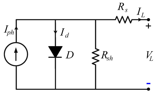
Figure 1.
PV equivalent circuit.
The output current IL generated by a cell or photovoltaic panel varies according to the voltage generated VL, due to the characteristics of the semiconductor material used in its manufacture. The current IL is the result of the current of the diode Id, which has an exponential characteristic, subtracted from the current Iph, which is the current generated by the incident light, as can be observed by the nodal analysis of the circuit shown in Figure 2, disregarding the current passing through Rsh.
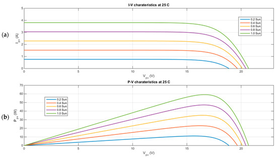
Figure 2.
Current-voltage and power-voltage characteristics of PV array at 25 °C andvarious irradiance levels.
Thus, the equation that describes the I–V curve that represents an ideal photovoltaic cell is [31]
in which the Ipv current generated by the incident light is given by
where
- Isc—panel short-circuit current [A];
- G—solar radiation [W/m²];
- Gnominal—nominal solar radiation [W/m²];
and Id represents Shockley’s equation, which describes the general characteristics of a semiconductor diode [32]:
where
- Io—leakage current or reverse saturation of the diode [A];
- q—electron charge (1.60217646 × 10⁻¹⁹ C);
- k—Boltzmann constant (1.3806503 × 10⁻²³ J/K);
- T—junction temperature p–n [K];
- A—diode ideality factor (1 ≤ to ≤2).
The addition of the Rsh and RS parameters to obtain the equivalent circuit of a real photovoltaic panel results in the addition of additional terms to Equation (1):
where NS is the number of cells connected in series and Vt is the panel thermal voltage given by
The panel temperature T is different from the ambient temperature (Tamb), and can be calculated by
where NOCT is the normal cell operating temperature when the irradiation is 800 W/m² and the ambient temperature is 20 °C.
The voltage and current levels generated by a photovoltaic panel vary according to solar irradiation conditions, temperature, time, day of the year, the orientation of the panels, panel inclination, geographic latitude and shading, among other factors. The electrical power P provided by photovoltaic panels is given by the multiplication of V by I and varies mainly according to solar irradiation (G) and temperature (T), as shown in Equations (2)–(5) and as shown in Figure 2a,b.
A PV module is subject to partial shading conditions when irradiation levels are not uniform in PV modules, as shown in Figure 3. Among the main consequences of partial shading in the PV arrangement are: losses due to heating and the appearance of several peaks in the PV curve, which directly affect the output power efficiency, as shown in Figure 4. For the losses due to heating in the PV arrangement, bypass and blocking diodes are used as a solution. Partial shading on a PV panel, whose PV cells are in series, transforms the shaded cells into charges for the other cells that act as sources. This causes the appearance of reverse currents, generating hot spots in the module and damaging it. Thus, it is normal to connect an antiparallel bypass diode to the PV cells. The bypass diode deflects the current from the PV cell, avoiding hot spots, and therefore limits the heat dissipation in the shaded cells.
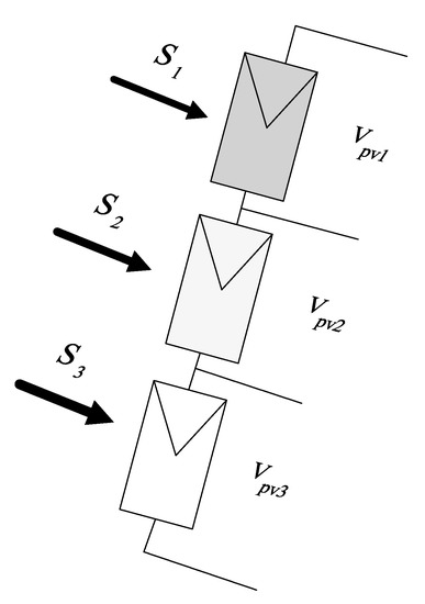
Figure 3.
PV under partial shading.
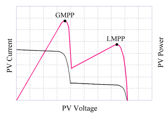
Figure 4.
PV V–I and V–P characteristics under partial shading.
The bypass diode method is the strategy most used in commercial devices. Although it manages to adequately deal with the phenomenon of hot spots and to preserve the life of the modules, there is still a serious problem related to the deformation of the P–V curve. This aspect is illustrated in Figure 4, in which the energy recovery provided by the method is observed, as well as the distortion of the P–V curve. In addition, it can be seen that, due to the distortion of the power curve, traditional MPPT methods such as P&O and IC are inefficient in this situation, as they can easily get lost in any of the several LMPPs, hence the need for more appropriate strategies to address this problem.
3. Firefly Algorithm
The FA is a recently studied population-based static heuristic, inspired by the social behavior of insects such as fireflies. Flashing lights are produced through thermal flashes, and each species has a unique flashing pattern. This pattern is used for mating or to attract possible prey, while the rhythm, the speed and the duration of the flash constitute a set of characteristics used for communication between individuals of the same kind. In some species, females can observe the signs of bioluminescence and even imitate the flashing patterns of other species, allowing them to attract males of other species to serve as food. In the FA algorithm, introduced by [33,34], the flashing patterns are used to simulate the mechanisms of communication between individuals of the same species. In this algorithm, the flashes of light and their intensity are associated with the value of the objective function to be optimized. For simplicity, three basic rules were considered in the elaboration of the algorithm: (a) fireflies are attracted to each other regardless of gender; (b) the attraction is proportional to intensity and decreases as the distance between two individuals increases, so fireflies of lesser brightness are attracted by fireflies of greater brightness; (c) the intensity of the flash is determined by the value of the objective function to be optimized, that is, I (x)/f (x).
The attraction is β proportional to the intensity of the flash. However, given that light is absorbed by the medium, the intensity decreases with the distance from the source. Considering a medium with a constant absorption coefficient γ, one can calculate the attraction between two adjacent fireflies using any decreasing monotone function, as shown in the following generalized model. Ideally, the light emitted by a source should be visible at any distance with the same intensity as that emitted. However, as the distance between the source and the observer increases, the intensity of the visible light decreases. This effect can be described by the law of the inverse of the square of the distance, presented in Equation (7) [34]:
In Equation (7), I(r) is the light intensity seen by the observer at a distance r from the source and Is is the light intensity at the source.
Another factor that also influences the light intensity seen by the observer is the absorption of light by the air, which also varies depending on the distance. This effect can be described by Equation (8).
In Equation (8), is the air absorption coefficient, a factor that determines the convergence of the algorithm, being able to assume values in the interval [0; ∞].
The attractiveness must be a monotonically decreasing function, being formulated according to the behavior of the light intensity in relation to the distance, considering the absorption of the air. Therefore, the attraction existing between a pair of fireflies can be formulated based on Equation (8), being given by Equation (9) [35]:
In Equation (9), β0 is the attractiveness at r = 0, being one of the parameters of the algorithm. For most problems, β0 = 1 can be used [35]. In turn, the distance between two fireflies i and j in positions xi and xj is given by Equation (10):
where xi;k is the k-th element of the spatial coordinate xi of the i-th particle and d is the number of dimensions. To determine the movement of firefly i in the direction of firefly j with greater brightness, Equation (10) is used [36]:
As in the other optimization methods, the firefly method optimizes a search that can be found in an n-dimensional space, even though the search for the GMPP is one-dimensional.
There are countless works involving the FA algorithm in solving different optimization problems such as: the synchronization of sensors in a network [37], power system stabilizers [38], the wireless network design [39], the optimization of mathematical functions [40], the resolution of an inverse problem of heat conduction, the treatment of optimization problems with the presence of reliability [41], structural optimization with mixed variables [42], the optimization of energy distribution systems [43], the design of mechanical systems [44], the selection of parameters in mechanical processes [45] and the optimization of shapes and sizes of mechanical structures [46].
Using FA in solving optimization problems overcomes the problem of having a large number of optimization algorithms which have constant parameters during the search process. Optimization algorithms with constant parameters affect the efficiency of the search in the real-time optimization process. In this context, the proposed method uses variable parameters with the ability to search in the opposite direction. Moreover, FA can always be able to find the optimal global solution for engineering systems.
In the firefly algorithm, there is no step to calculate the comparative individual aptitude values. Therefore, the particles do not return to their original position when no benefits result from their first move, always then moving again towards their closest best neighbor. To overcome this drawback, the opposition-based learning method allows FA to search for the optimal point in the opposite direction of the current search. Figure 5 shows the flowchart for the firefly optimization method, where VPV is the measured PV voltage, VPV_MPP is the voltage at the maximum power point and PPV is the PV power.
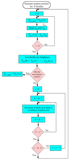
Figure 5.
Flowchart for maximum power point tracking using firefly optimization.
4. Opposition-Based Learning Method (OBL)
The OBL was used as an easy implementation technique allowing the bio-inspired algorithms to search for the optimal point in the opposite direction of the last search. The basic idea of this technique is that when performing a local search in one direction, it is important to also consider what lies in the opposite direction [47,48]. In this way, the OBL method allows us to improve the quality of the solution and preserve the diversity of the swarm. The OBL approach is based on the concept of the opposite number, defined by Equation (12):
x is an actual number defined in the range [a; b] and is the opposite number of x. This stage is also valid for N-dimensional points xi defined in the range [ai; bi], i = 1; 2; …; N.
The OBL technique was used with genetic algorithms in which the concept of anti-gene accelerates the search process. In this sense, OBL was also applied to artificial neural networks with the same idea of inverting the network weight in the training of artificial neural networks, and this improved the results [39]. Recently, the OBL technique has also been applied to different applications and different optimization methods such as differential evolution algorithms (DE) [49], optimization by ant colony [50] and PSO [42,51].
In the OFA, the opposite value of xi in Equation (10) is calculated for all values from i = 1 to N and then the best solution of xi and xopposite is used to find the Vpv_MPP shown in the flowchart in Figure 6.
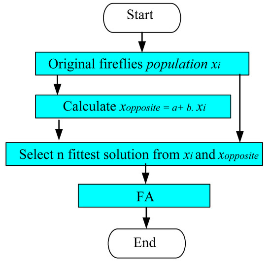
Figure 6.
Opposition-based learning process, OBL-FA.
5. System Description
The block diagram of the actual PV grid-connected system studied in this paper is shown in Figure 7. The system consists of a 60 Wp PV panel, which is connected to the DC-AC inverter by a boost converter. The DC-AC conversion is performed by the inverter, and the inverter is joined to the grid by a connection filter. The inverter regulates the DC-link voltage and adjusts the power factor of the sinusoidal output current to unity. The controller consists of two loops in which the outer loop is the DC-link voltage controller, and the inner is the output current controller. The boost converter controls the PV output power to track the maximum power point, by adjusting the PV voltage to the optimum point. The MPPT algorithm generates a reference current Vpv* that is then applied to a PI controller to maintain the PV array’s output voltage to the optimum value. The block diagrams of the boost converter and inverter controllers are shown in Figure 8a,b.
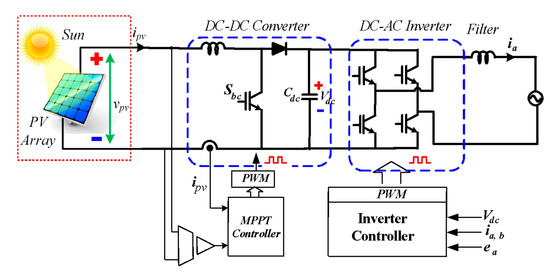
Figure 7.
PV grid-connected system.
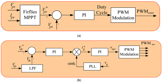
Figure 8.
PV control system: (a) DC-DC converter, (b) DC-AC inverter.
6. Experimental Results
To evaluate the performance of the firefly method, an experimental setup was implemented using DSpace (Microlabbox) and utilizing the PLL algorithms, the DC-link voltage controller and the DC-DC and DC-AC current (PI) controllers of the PV system, as shown in Figure 9 [52]. Insulated Gate Bipolar Transistor (IGBT) modules (SK40GB 123, SEMIKRON) with their respective drivers make up the complete bridge inverter connected to the network. The switching frequencies of the inverter, as well as the DC-DC boost converter, were fixed at 10 kHz. In addition, current (LEM LA 100-P) and voltage (LEM LV 25-P) transducers were used to measure the current and voltage quantities. Figure 8 demonstrates the experimental setup.

Figure 9.
PV system setup.
The MPPT algorithms were evaluated under three different operating conditions of the PV system. In the first (Criteria 1), the irradiance level was kept constant, while under the second and third conditions (Criteria 2 and 3), the PV array operated in conditions of partial shading. Figure 10 shows the P–V characteristic curves for Criteria 1, Criteria 2 and Criteria 3, respectively.
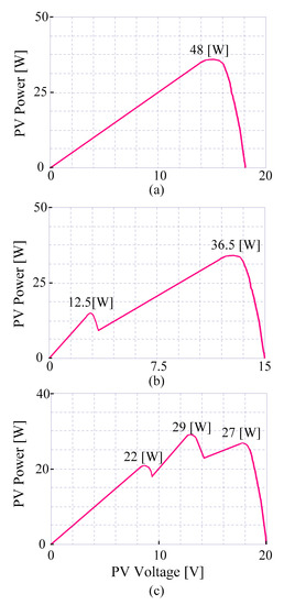
Figure 10.
PV characteristics: (a) Criteria 1, (b) Criteria 2, (c) Criteria 3.
Figure 11 illustrates the PV voltage, current and power during constant irradiance conditions. From the PV array characteristics, it can be seen that all MPPT methods achieved a GMPP of 48 [W]. The OFA algorithm presented the shortest convergence time, as shown in Figure 11a. When FA was used alone, the convergence time increased due to the continuous search for the GMPP, as shown in Figure 11b. The P&O algorithm took longer to reach the MPPT point and suffered from continuous oscillations around the MPP, as shown in Figure 11c.
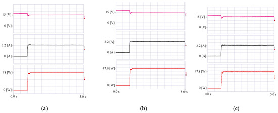
Figure 11.
Experimental results of maximum power point tracking (MPPT) techniques considering Criteria 1 for the algorithms: (a) OFA; (b) FA; (c) P&O.
Table 2 summarizes the experimental results involving the three MPPT algorithms operating under conditions of uniform solar irradiance.
Table 2.
Summary of OFA, FA and P&O performance comparison (Criteria 1).
For Criteria 2, Figure 12a–c show the powers extracted from the photovoltaic array using the OFA, FA and P&O MPPT techniques, respectively. It was observed that the GMPP was almost achieved in all the MPPT methods, and of the hybrid methods, the OFA presented the fewest power oscillations and the shortest convergence time in achieving the GMPP. The average power of the FA and P&O was slightly less than that of the OFA.
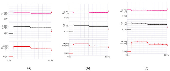
Figure 12.
Experimental results of MPPT techniques considering Criteria 2 for the algorithms: (a) OFA; (b) FA; (c) P&O.
It was also noticed that even after reaching the steady state, the MPPT-P&O method exhibited the longest convergence time and also an oscillation around the tracked power point. On the other hand, the power extracted using the MPPT-OFA method showed the smallest power oscillation of all the methods. From the experimental results, it is noticeable that OFA MPPT converged quickly to the GMPP and not to the LMPP.
Table 3 summarizes the main results obtained from the experiments involving the three MPPT algorithms operating under Criteria 2.
Table 3.
Summary of OFA, FA and P&O performance comparison (Criteria 2).
The OFA method uses random variables with the ability to reverse the search direction by the OBL algorithm to scan the curve of the PV array, converging to points close to the GMPP.
The powers extracted for Criteria 3, shown in Figure 13a–c, show that the MPPT-P&O method tracked a local maximum point, E, with a power of 21.5 W. The MPPT-OFA method was able to track the maximum global power available in the photovoltaic array, whose approximate power was 29 W.
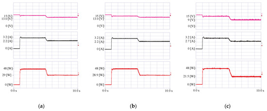
Figure 13.
Experimental results of MPPT techniques considering Criteria 3 for the algorithms: (a) OFA; (b) FA; (c) P&O.
Table 4 summarizes the main results obtained from the experiment involving the three MPPT algorithms operating under partial shading conditions (Criteria 3).
Table 4.
Summary of OFA, FA and P&O performance comparison (Criteria 3).
The OFA MPPT method stood out with the best overall performance, justifying the use of this algorithm. The advantage of applying this combined optimization technique is that it can determine the tracking performed by the random search approaching the tracked point of the GMPP, thus increasing the effectiveness of the algorithm. In addition, the algorithm is able to keep GMPP tracked even with small changes in climatic conditions since there is scope for the random search to restart, which is not possible through techniques based only on meta-heuristic optimization. Thus, losses are minimized, and the performance of the algorithm becomes superior.
7. Conclusions
This paper presented an opposition-based learning firefly-based (OFA) MPPT algorithm for extracting the maximum power from photovoltaic arrays. The MPPT implementation does not require sensors over and above those used by the control structure. The proposed MPPT was also analyzed under various levels of irradiance, and under partial shading conditions. The efficiency of the algorithm presented was validated by comparison with the FA and P&O algorithms. From the results obtained using the real experimental system, it was demonstrated that the OFA MPPT algorithm was able to quickly converge to the GMPP when the photovoltaic arrangement was operating in standard conditions, as well as when it was subjected to partial shading conditions. The efficiency of the OFA in searching the MPP was always close to 100% in all the patterns tested, with a power oscillation of less than 1%. Using FA without the ability to search in the opposite direction affected the efficiency, which was about 99.8% during uniform irradiance and became 99% during partial shading. The P&O method a exhibited high efficiency of 99.6% under conditions of uniform irradiance and became 74.2% under partial shading conditions, when the MPPT was stuck in an LMPP. Another advantage of the OFA MPPT method lies in the algorithm’s ability to refine the MPPT scan and thus achieve the GMPP very quickly. In addition, the OFA was able to search for the GMPP during small variations in solar irradiance, without the need to perform a completely new search on the characteristic curve of the PV arrangement. Thus, the OFA MPPT algorithm showed reduced power oscillations under steady-state conditions and greater tracking efficiency in the search for the GMPP. In this way, the proposed MPPT reached the MPP quickly, accurately and without adding costs to the PV systems.
Author Contributions
Conceptualization, A.G.A.-K. and W.A.; methodology, A.G.A.-K.; software, I.M.A.; validation, M.A. and A.-R.A.-Q.; formal analysis, W.A.; investigation, M.A.; resources, M.A.; data curation, W.A.; writing—original draft preparation, A.G.A.-K.; writing—review and editing, A.-R.A.-Q.; visualization, I.M.A.; supervision, W.A.; project administration, M.A.; funding acquisition, W.A. All authors have read and agreed to the published version of the manuscript.
Funding
This research received no external funding.
Institutional Review Board Statement
Not applicable.
Informed Consent Statement
Not applicable.
Data Availability Statement
The used or generated data and the result of this study are available upon request from the corresponding author.
Acknowledgments
The authors extend their appreciation to the Deputyship for Research and Innovation, Ministry of Education in Saudi Arabia, for funding this research work through project number (IFP-2020-04).
Conflicts of Interest
The authors declare no conflict of interest.
References
- Almutairi, A.; Abo-Khalil, A.G.; Sayed, K.; Albagami, N. MPPT for a PV grid-connected system to improve efficiency under partial shading conditions. Sustainability 2020, 12, 310. [Google Scholar] [CrossRef]
- De Brito, M.A.G.; Galotto, L.; Sampaio, L.P.; Melo, G.D.A.E.; Canesin, C.A. Evaluation of the Main MPPT Techniques for Photovoltaic Applications. IEEE Trans. Ind. Electron. 2013, 60, 1156–1167. [Google Scholar] [CrossRef]
- Premkumar, M.; Sumithira, T.R.; Sowmya, R. Implementation of Solar PV Based Microconverter With Optimal Mppt Control. J. Electr. Eng. 2018, 18, 1–12. [Google Scholar]
- Pakkiraiah, B.; Sukumar, G.D. Research Survey on Various MPPT Performance Issues to Improve the Solar PV System Efficiency. J. Sol. Energy 2016, 2016, 1–20. [Google Scholar] [CrossRef]
- Abokhalil, A.G.; Awan, A.B.; Al-Qawasmi, A.R. Comparative study of passive and active islanding detection methods for PV grid-connected systems. Sustainability 2018, 10, 1798. [Google Scholar] [CrossRef]
- Hohm, D.P.; Ropp, M.E. Comparative study of maximum power point tracking algorithms. Prog. Photovolt. Res. Appl. 2003, 11, 47–62. [Google Scholar] [CrossRef]
- Ahmed, J.; Salam, Z. An Enhanced Adaptive P&O MPPT for Fast and Efficient Tracking Under Varying Environmental Conditions. IEEE Trans. Sustain. Energy 2018, 9, 1487–1496. [Google Scholar] [CrossRef]
- Elgendy, M.A.; Zahawi, B.; Atkinson, D.J. Assessment of Perturb and Observe MPPT Algorithm Implementation Techniques for PV Pumping Applications. IEEE Trans. Sustain. Energy 2012, 3, 21–33. [Google Scholar] [CrossRef]
- Masood, B.; Siddique, M.S.; Asif, R.M.; Zia-ul-Haq, M. Maximum power point tracking using hybrid perturb & observe and incremental conductance techniques. In Proceedings of the 2014 4th International Conference on Engineering Technology and Technopreneuship (ICE2T), Kuala Lumpur, Malaysia, 27–29 August 2014; pp. 354–359. [Google Scholar]
- Safari, A.; Mekhilef, S. Incremental conductance MPPT method for PV systems. In Proceedings of the 24th Canadian Conference on Electrical and Computer Engineering(CCECE), Niagara Falls, ON, Canada, 8–11 May 2011; pp. 345–347. [Google Scholar]
- Hussein, K.H.; Muta, I.; Hoshino, T.; Osakada, M. Maximum Photovoltaic Power Tracking: An Algorithm for Rapidly Changing Atmospheric Conditions. IEEE Proc. Gener. Transm. Distrib. 1995, 142, 59–64. [Google Scholar] [CrossRef]
- Yu, B.; Abo-Khalil, A.G. Current Estimation-Based Maximum Power Point Tracker of Grid Connected PV. Power Electronics and Drives Systems (PEDS). In Proceedings of the 2013 IEEE 10th International Conference on Power Electronics and Drive Systems (PEDS), Kitakyushu, Japan, 22–25 April 2013. [Google Scholar]
- Yu, B.; Abo-Khalil, A.G.; Matsui, M.; Yu, G. Sensorless Fuzzy Logic Controller for Maximum Power Point Tracking of Grid- Connected PV system. In Proceedings of the International Conference on Electrical Machines and Systems ICEMS, Tokyo, Japan, 15–18 November 2009. [Google Scholar]
- Kottas, T.L.; Boutalis, Y.S.; Karlis, A.D. New maximum power point tracker for PV arrays using fuzzy controller in close cooperation with fuzzy cognitive networks. IEEE Trans. Energy Convers 2006, 21, 793–803. [Google Scholar] [CrossRef]
- Abo-Khalil, A.G.; Lee, D.C.; Choi, J.W.; Kim, S.G. Maximum Power Point Tracking Controller Connecting PV System to Grid. J. Power Electron. 2006, 6, 226–234. [Google Scholar]
- Syafaruddin, E.; Karatepe, T. Hiyama Artificial neural network-polar coordinated fuzzy controller based maximum power point tracking control under partially shaded conditions. IET Renew. Power Gener. 2009, 3, 239–253. [Google Scholar] [CrossRef]
- Veerachary, M.; Senjyu, T.; Uezato, K. Neural-network-based maximum-power-point tracking of coupled-inductor interleaved-boost converter- supplied PV system using fuzzy controller. IEEE Trans. Ind. Electron. 2003, 50, 749–758. [Google Scholar] [CrossRef]
- Eltamaly, A.M.; Al-Saud, M.S.; Abo-Khalil, A.G.; Farah, H. Simulation and Experimental Validation of Fast Adaptive Particle Swarm Optimization Strategy for Photovoltaic Global Peak Tracker under Dynamic Partial Shading. Renew. Sustain. Energy Rev. 2020, 124, 109719. [Google Scholar] [CrossRef]
- Eltamaly, A.M.; Al-Saud, M.S.; Abo-Khalil, A.G. Performance Improvement of PV Systems’ Maximum Power Point Tracker Based on a Scanning PSO Particle Strategy. Sustainability 2020, 12, 1185. [Google Scholar] [CrossRef]
- Putri, R.I.; Wibowo, S.; Rifa’I, M. Maximum Power Point Tracking for Photovoltaic Using Incremental Conductance Method. Energy Procedia 2015, 68, 22–30. [Google Scholar] [CrossRef]
- Yu, B.G.; Abo-Khalil, A.G.; Matsui, M.; Yu, G.J. Support Vector Regression Based Maximum Power Point Tracking for PV Grid-Connected System. In Proceedings of the 2009 34th IEEE Photovoltaic Specialists Conference (PVSC), Philadelphia, PA, USA, 7–12 June 2009. [Google Scholar]
- Eltamaly, A.M.; Al-Saud, M.S.; Abokhalil, A.G.; Farh, H.M. Photovoltaic maximum power point tracking under dynamic partial shading changes by novel adaptive particle swarm optimization strategy. Trans. Inst. Meas. Control. 2019, 42, 104–115. [Google Scholar] [CrossRef]
- Abo-Khalil, A.G. Maximum Power Point Tracking for a PV System Using Tuned Support Vector Regression by Particle Swarm Optimization. J. Eng. Res. 2020, 8, 139–152. [Google Scholar] [CrossRef]
- Pilakkat, D.; Kanthalakshmi, S. An improved P&O algorithm integrated with artificial bee colony for photovoltaic systems under partial shading conditions. Sol. Energy 2019, 178, 37–47. [Google Scholar] [CrossRef]
- Eltamaly, A.M.; Al-Saud, M.S.; Abo-Khalil, A.G. A Novel Bat Algorithm Strategy for Maximum Power Point Tracker of Photovoltaic Energy Systems under Dynamic Partial Shading. IEEE Access 2020, 8, 10048–10060. [Google Scholar] [CrossRef]
- Messalti, A.H.S. Variable step size modified P&O MPPT algorithm using GA-based hybrid offline/online PIDcontroller. Renew Sustain. Energy Rev. 2015, 49, 1247–1260. [Google Scholar]
- Abo-Khalil, A.G.; Lee, D.-C.; Seok, J.-K.; Choi, J.-W.; Kim, H.-G. Maximum Power Point Tracking for Photovoltaic System Using Fuzzy Logic Controller. In Proceedings of the KIPE Power Electronics Annual Conference, Hyundai Seongwoo Resort, Gangwon, Korea, 14–17 June 2003; Volume 2, pp. 503–507. [Google Scholar]
- Eltamaly, A.M.; Farh, H.M.H.; Abokhalil, A.G. A novel PSO strategy for improving dynamic change partial shading photovoltaic maximum power point tracker. Energy Sources Part A Recover. Util. Environ. Eff. 2020, 1–15. [Google Scholar] [CrossRef]
- Farh, H.M.H.; Othman, M.F.; Eltamaly, A.M.; Al-Saud, M.S. Maximum Power Extraction from a Partially Shaded PV System Using an Interleaved Boost Converter. Energies 2018, 11, 2543. [Google Scholar] [CrossRef]
- Seyedmahmoudian, M.; Rahmani, R.; Mekhilef, S.; Oo, A.M.T.; Stojcevski, A.; Soon, T.K.; Ghandhari, A.S. Simulation and Hardware Implementation of New Maximum Power Point Tracking Technique for Partially Shaded PV System Using Hybrid DEPSO Method. IEEE Trans. Sustain. Energy 2015, 6, 850–862. [Google Scholar] [CrossRef]
- Eltamaly, M.A.; Farh, H.M.H.; Al Saud, M.S. Impact of PSO reinitialization on the accuracy of dynamic global maximum power detection of variant partially shaded PV systems. Sustainability 2019, 11, 2091. [Google Scholar] [CrossRef]
- Chao, R.-M.; Nasirudin, A.; Wang, I.-K.; Chen, P.-L. Multicore PSO Operation for Maximum Power Point Tracking of a Distributed Photovoltaic System under Partially Shading Condition. Int. J. Photoenergy 2016, 2016, 1–19. [Google Scholar] [CrossRef]
- Yang, X.-S. Multiobjective firefly algorithm for continuous optimization. Eng. Comput. 2013, 29, 175–184. [Google Scholar] [CrossRef]
- Yang, X.-S. Chaos-Enhanced Firefly Algorithm with Automatic Parameter Tuning. Int. J. Swarm Intell. Res. 2011, 2, 1–11. [Google Scholar] [CrossRef]
- Yang, X.S. A New Metaheuristic Bat-Inspired Algorithm. In Nature Inspired Cooperative Strategies for Optimisation; Gonzalez, J.R., Ed.; Springer: Berlin/Heidelberg, Germany, 2010; pp. 65–74. [Google Scholar]
- Yang, X.S. Firefly algorithm, stochastic test functions and design optimization. Int. J. Bio-Inspired Comput. 2010, 2, 78–84. [Google Scholar] [CrossRef]
- Werner-Allen, G.; Tewari, G.; Patel, A.; Welsh, M.; Nagpal, R. Firefly-inspired sensor network synchronicity with realistic radio effects. In Proceedings of the 3rd International Conference on Embedded Networked Sensor Systems, New York, NY, USA, 2–4 November 2005; pp. 142–153. [Google Scholar]
- Das, T.K.; Venayagamoorthy, G.K. Bio-inspired algorithms for the design of multiple optimal power system stabilizers: SPPSO and BFA. In Proceedings of the Conference Record of the 2006, IEEE Industry Applications Conference, Forty-First IAS Annual Meeting, Tampa, FA, USA, 8–12 October 2006; Volume 2, pp. 635–641. [Google Scholar]
- Leidenfrost, R.; Elmenreich, W. Establishing wireless time-triggered communication using a firefly clock synchronization approach. In Proceedings of the 2008 International Workshop on Intelligent Solutions in Embedded Systems, Regensburg, Germany, 10–11 July 2008; pp. 1–18. [Google Scholar]
- Yang, X.S. Nature-Inspired Metaheuristic Algorithms; Luniver Press: Bristol, UK, 2008. [Google Scholar]
- Coelho, L.S.; Mariani, V.C. Combining of chaotic differential evolution and quadratic programming for economic dispatch optimization with valve-point effect. IEEE Trans. Power Syst. 2006, 21, 989–996. [Google Scholar]
- Gandomi, A.H.; Yang, X.-S.; Alavi, A.H. Mixed variable structural optimization using Firefly Algorithm. Comput. Struct. 2011, 89, 2325–2336. [Google Scholar] [CrossRef]
- Coello, C.A.C.; Becerra, R.L. Efficient evolutionary optimization through the use of a cultural algorithm. Eng. Optim. 2004, 36, 219–236. [Google Scholar] [CrossRef]
- Baykasouglu, A.; Ozsoydan, F.B. Adaptive firefly algorithm with chaos for mechanical design optimization problems. Applied Soft Computing 2015, 36, 152–164. [Google Scholar] [CrossRef]
- Shukla, R.; Singh, D. Selection of parameters for advanced machining processes using firefly algorithm. Eng. Sci. Technol. Int. J. 2017, 20, 212–221. [Google Scholar] [CrossRef]
- Lieu, Q.X.; Do, D.T.; Lee, J. An adaptive hybrid evolutionary firefly algorithm for shape and size optimization of truss structures with frequency constraints. Comput. Struct. 2018, 195, 99–112. [Google Scholar] [CrossRef]
- Tizhoosh, H.R. Opposition-based learning: A new scheme for machine intelligence. In Proceedings of the International Conference on Computational Intelligence for Modelling, Control and Automation, Vienna, Austria, 28–30 November 2005; pp. 695–701. [Google Scholar]
- Alqunaieer, F.; Tizhoosh, H.; Rahnamyan, S. Opposition based computing—A survey. In Proceedings of the International Joint Conference on Neural Networks, Barcelona, Spain, 18–23 July 2010; pp. 1098–7576. [Google Scholar]
- Rahnamayan, S.; Tizhoosh, H.R.; Salama, M.M. Opposition versus randomness in soft computing techniques. Appl. Soft Comput. 2008, 8, 906–918. [Google Scholar] [CrossRef]
- Malisia, A. Applying opposition-based ideas to the ant colony system. In Proceedings of the IEEE Swarm Intelligence Symposium, Honolulu, HI, USA, 1–5 April 2007; pp. 182–189. [Google Scholar]
- Eltamaly, A.M.; Al-Saud, M.S.; Sayed, K.; Abo-Khalil, A.G. Sensorless Active and Reactive Control for DFIG Wind Turbines Using Opposition-Based Learning Technique. Sustainability 2020, 12, 3583. [Google Scholar] [CrossRef]
- Abo-khalil, A.G.; Al-Qawasmi, A.; Eltamaly, A.M.; Yu, B.G. Condition Monitoring of DC-Link Electrolytic Capacitors in PWM Power Converters Using OBL Method. Sustainability 2020, 12, 3719. [Google Scholar] [CrossRef]
Publisher’s Note: MDPI stays neutral with regard to jurisdictional claims in published maps and institutional affiliations. |
© 2021 by the authors. Licensee MDPI, Basel, Switzerland. This article is an open access article distributed under the terms and conditions of the Creative Commons Attribution (CC BY) license (http://creativecommons.org/licenses/by/4.0/).