Abstract
Construction Progress monitoring noticed recent expansions by adopting vision and laser technologies. However, inspectors need to personally visit the job-site or wait for a time gap to process data captured from the construction site to use for inspection. Recent inspection methods lacks automation and real-time data exchange, therefore, it needs inspection manpower for each job-site, the health risk of physical interaction between workers and inspector, loss of energy, data loss, and time consumption. To address this issue, a near real-time construction work inspection system called iVR is proposed; this system integrates 3D scanning, extended reality, and visual programming to visualize interactive onsite inspection for indoor activities and provide numeric data. The iVR comprises five modules: iVR-location finder (finding laser scanner located in the construction site) iVR-scan (capture point cloud data of job-site indoor activity), iVR-prepare (processes and convert 3D scan data into a 3D model), iVR-inspect (conduct immersive visual reality inspection in construction office), and iVR-feedback (visualize inspection feedback from job-site using augmented reality). An experimental lab test is conducted to verify the applicability of iVR process; it successfully exchanges required information between construction job-site and office in a specific time. This system is expected to assist Engineers and workers in quality assessment, progress assessments, and decision-making which can realize a productive and practical communication platform, unlike conventional monitoring or data capturing, processing, and storage methods, which involve storage, compatibility and time-consumption issues.
1. Introduction
The construction industry has devoted significant efforts toward sustainable construction by utilizing automation and vision technologies [1,2]. Especially, Construction progress monitoring has been leveraged to increase accuracy and time efficiency [3,4]. This includes measuring the progress through site assessments and comparisons with the project plan; in these methods, the quality of progress data completely depends on the expertise of inspection and the measurement quality [5].
Generally, manual visual observations and conventional progress tracking can be used to provide feedback on progress measurement [3], productivity rate [5], tracking devices and materials [6], and safety planning [7]. Work inspection engineers typically adhere to guidelines provided by construction quality control institutes like the International Organization for Standardization (ISO)(accessed on 22 December 2020). One of the primary aims of inspection is to evaluate dimensional (dimension and position) errors and surface defects (cracks and spalling) in activities involving concrete columns and HVAC pipes [8]. However, conventional methods for construction work inspection are time-consuming, needs inspection manpower [9], consume energy, economically, inefficient and prone to errors [10]. Therefore a more sustainable and automated construction progress monitoring needs to be developed to operate at a lower cost, less manpower, and a healthier construction environment by reducing the physical interaction between construction worker and inspector.
In South Korea, 194,947 new construction projects started in 2019 graciously according to the Korean statistical information services (accessed on 10 December 2020). Considerable amounts of these buildings are small construction projects. Inspection and continue monitoring of this considerable number of projects consume a lot of manpower, time, data management, and travel between sites which will cause pollution, energy and economic loss, and higher risk [1,9]. Therefore, remote monitoring of multiple activities at the same time using extended reality technologies might reduce the number of inspectors needed [11].
Building information modeling (BIM) technology, which is routinely used in the construction industry, is a potential solution for achieving automation in work inspection. BIM is a rich source of 3D geometry-related information like mechanical, electrical, plumbing, architectural, and structural data; BIM also facilitates knowledge-sharing of building life-cycles and resolves interoperability issues [2,11]. The advancement of contemporary technologies in project delivery has led to the cognitive development of faster and more efficient digital models [11]. These modern technologies employ digital platforms of computers, mobile devices, sensors, broadband network connections, and application platforms [10], which facilitate the sustainable growth of activities and relationships around the management office and job-site in the construction stage.
Although researchers are developing techniques to employ augmented reality (AR) for monitoring construction progress, existing practices rely on fairly manual and time-consuming inspections to assess the progress at most construction sites; however, these approaches are prone to factual errors [12]. Moreover, even after implementing BIM software, the software is not updated in real-time between the construction office and the construction site. This leads to a lack of creativity anticipated to arise from digitization and the use of 3D technologies [3].
It is challenging for engineers at the construction site to manage complicated BIM models and recognize the necessary attributes contained in digital models. As BIM models are maintained on servers or separate computers, they cannot be synchronously modified on a job-site. Thus, information transfer from the design office to the engineering office at the construction site is delayed considerably [13]. This delay can be critical in some projects, such as fast-tracked projects, where the design is developed simultaneously with the construction. Slower data exchange can result in the slowdown or rework of the project [5]. Therefore, developing a method for near real-time monitoring of construction projects and bridging the gap between indoor job-site activities and construction offices represent an urgent need in the construction industry [13]. These activities are conducted inside an enclosed space, limited to conditions of the place it is held in, the number of workers participating in it, objects being constructed, among other activities.
This article proposes one platform that can host multiple monitoring tasks and transfer data between them smoothly). This platform propose a closed loop of communication between construction job-site and construction offices during the inspection process. This study aims to minimize the gap between job sites and construction offices by developing a system that can realize work inspection and quality assessment of data in near real-time for indoor activities. The developed system prototype can: (1) capture point cloud data of constriction indoor activity, (2) convert the point cloud into 3D model, (3) monitor progress in an office using virtual reality (VR), and (4) enables workers at job-site to visualize the inspector’s report in AR. Moreover, two case studies of column and HVAC pipe quality assessment are successfully implemented to test the applicability of iVR process, and the results of the system are registered. This research scope is limited to target indoor activities excludes other monitoring aspects such as worker, surroundings, and temporary facilities.
2. Literature Review
To demonstrate the integration of 3D scanning and extended reality for onsite progress monitoring, this study considers various technical challenges of 3D laser scanning and extended reality, including interdependency, spatial site layout collision, analyses, and management, digital to a physical link, project control, and design visualization during production.
In the Construction processes, the term ’sustainability’ connotes ’efficiency’ that considers as the key aspect, integrating building automation system in construction activities, including progress monitoring to reduce workforce, increase efficiency, create a healthier and safer environment by minimizing the physical interaction between inspectors and workers in the job-site [1,4]. In more detail, a point cloud is applied for different phases with various targets, including planning and design, manufacturing and construction, and operation and maintenance. In the planning and design stage, a point cloud is used to reconstruct 3D models of the site and existing buildings [14,15]. In the manufacturing and construction phase, a point cloud is applied for automating construction equipment [13], digital reproduction [4,16], identification of safety hazards [17], monitoring of construction progress [18], and inspection of construction quality [17]. In the operation and maintenance phase, a point cloud is applied for reconstructing 3D architectural structures [15], building performance analyses [19], facility management for 3D model reconstruction [12], and inspection of building quality [18,19].
As-built point clouds can be acquired using laser scanning or image-based photogrammetry methods. The generated point clouds are co-registered with the model by using an adapted iterative-closest point (ICP) algorithm, and the as-planned model is transformed in to a point cloud by simulating the points using the recognized positions of the laser scanner. Recently, researchers have developed systems that can detect different component categories using a supervised classification based on features obtained from the as-built point cloud; after that, an object can be detected if the classification category is identical to that in the model [3,20,21].
Utilizing cameras as the acquisition tool results in lower geometric accuracy, as compared to that obtained by laser scanning point clouds. A few recent studies have detected spatial differences between time frame images [16,22] and updated the project schedule using images [7], and compare as-built to as planned BIM model. The Kinect 3D scanner employs the similar technology as that of a mid-range 3D scanner, i.e., a camera and an infrared camera to calculate the depth field of an object and its surroundings. These two “cameras” used in the Kinect enable it to scan nearly every chosen item, with decent 3D accuracy. The depth camera has been employed for the surveillance and assessment of construction sites, tracking of materials, equipment, and labor [23], safety monitoring [24], and reconstruction [2,18]. Recently, advanced technologies such as robotics and drones have been proposed in the construction site to aid or replace workers which need real time remote monitoring technology that can be integrated with its own system such as facade pick-and-place using robot arm [25], brick laying using drone [26], humanoid robotics [27], and integrating site terrain with BIM model [28].
The construction industry has explored reconstruction architectures using active scanners, 3D laser scanners, and passive cameras. However, such equipment has not been implemented in real-world applications thus far. Moreover, state-of-the-art methods necessitate high computational resources to analyze 3D points and varying dynamic scenes. However, the incorporation of Kinect low-cost scene scanners can enable the rapid replication of 3D models with improved size and resolution. Several simultaneous localization and mapping systems have used sparse maps to locate and focus on real-time tracking [24]. Moreover, other methodologies have also been used for reconstructing simple point-based representations [15]. Kinect cameras exceed such point-based representations by reconstructing surfaces that approach real-world geometry, with greater reliability [2,29].
The extended reality in construction progress monitoring Immersive simulation improves the comprehension of dynamic construction processes and promotes the assessment of different project conditions with minimal cost and intervention [30]. On top of that, Building professionals and researchers perceive the value of simulations and have been exploring the use of VR for interactive visualization. Potential experiments in this area include construction defect management [31], information delivery in the excavation stage [32,33], dynamic visualization using GPS [34,35]. Cloud-based computing represent another field that has enabled real-time coordination and empowered project teams to expand BIM from the design to planning stages. BIM-based platforms have recently facilitated real-time collaboration in cloud computing. However, cloud-based BIM data-exchange protocols, resource management, and connection to construction sites however lack real-time and user-friendly tools. Research review advances the principle of construction scheduling automation.
Although laser scanning data have been widely utilized for the dimensional and surface engineer in various civil applications and project quality checking, its integration with visual algorithms and extended reality technologies is important to explore more to encourage remote monitoring without the need to visit a job-site in person. Therefore, this paper proposes a laser scanning-based, accurate, and reliable technique for near real-time assessment of dimensional and surface quality, to reduce the gap between construction offices and job sites by integrating the Kinect 3D scanning and extended reality.
3. Methodology
The proposed framework incorporates knowledge transfer from the job-site to the construction office and vice versa. The core feature of this framework is to integrate a monitoring device with extended reality technology in one platform that syncs between the construction office and job-site in near real-time. The following research questions are asked: One, how can the inspector monitoring indoor activity remotely from the construction site using extended reality? Two, how to erect one platform that can capture activity 3d information, dispatch it to the construction office, generate inspection report, and send it back to construction site in near real time? Three, can we utilize virtual and augmented reality for activity inspection in an integrated platform.
The research methodology is divided into three sections: (1) inspection checklist, which explains the method to build the inspection agenda in VR; (2) laser scanner and extended reality-based quality inspection procedure (iVR), which addresses the system architecture of the proposed methodology; and (3) data storage and data compatibility, which discusses innovative methods of storing data exchange between job-site and construction office. The proposed system, iVR, comprises the following five modules: (1) iVR-location finder that optimizes laser scanner device location in the physical model; (2) iVR-scan which captures point cloud of target activity using 3D laser scanners; (3) iVR-prepare converts point cloud into a 3D mesh geometry; (4) iVR-inspect that let site engineer generate a quality check and feedback report using VR, and (5) iVR-feedback visualizes of inspection feedback in job-site using the AR (iVR-feedback) module.
Generally, iVR-location finder helps inspector find the best laser scanner position to monitor the targeted activity in the construction site and view how the point cloud data will look like before monitoring activity starting and pass position coordinates to iVR-scan so that the inspector position the laser scanner in the correct position in the physical site following the digital position optimized using iVR-location finder module. Next, the iVR-scan starts capturing point cloud data of target activity and passes it to iVR prepare where it converts received data into 3D mesh geometry and sends it from the construction office to iVR-inspect in the construction office. After that, the inspector measures progress checking, quality control in virtual reality mode, and sends the inspection report back to the construction site. Finally, the worker views the inspection report in augmented reality hosted inside the iVR-feedback module.
3.1. Inspection Checklist
Before performing progress monitoring, it is essential to identify the inspection checklist, which includes the attributes of activity elements that need to be inspected and their required degree of accuracy. Generally, the construction specifications of a project play a major role in determining the inspection checklist. These specifications detail the quality requirements for each component of the construction project, which can then be translated into the inspection checklist. In this study, the inspection checklist is determined based on the tolerance manual for object placement and casting tolerance in the guide for concrete columns provided by the American Concrete Institute. Table 1 displays the checklists listed, which comprise two sections: geometry and defects. Existent two characteristics for the geometry category: dimension and location of concrete components. Each dimensional function has its checklist, which is referred to as “attributes.” For instance, height, width, and thickness are characteristics of the “scale” function. The resistance of each feature differs with the form of design, item size, and product duration. It also presents tolerances for an exemplary concrete column and HVAC pipe. Each dimensional attribute should be carefully checked to ensure that its value lies within the predefined tolerance. Otherwise, the dimensional errors in each prefixed variable will aggregate in the prefix segment. There are three characteristics of defect: spalling, crack, and flatness.

Table 1.
Inspection checklists for indoor geometry.
3.2. Extended Reality Based Progress Monitoring System (iVR)
After determining the checklist and required tolerances for inspection, an inspection protocol must be conducted. iVR system comprises four modules: module 1, which involves capturing the site model using 3D laser scanners (iVR-scan), module 2, in which the point cloud is converted into a 3D mesh (iVR-prepare), module 3, which involves the quality check by the site engineer and the feedback report generation using VR (iVR-inspection), and module 4 in which the inspection feedback is visualized in job-site using AR ( iVR-feedback). In more detail, 3D laser scanners are used to capture point clouds of activities, which are then converted into 3D models and sent to the building information modeling cloud of the construction office by the iVR-prepare algorithm. Subsequently, iVR-inspect enables engineers to trace workflow, compare current project progress with blueprints, measure objects, and add text/design notes to 3D models, to leverage the quality of project site management. Finally, iVR-feedback sends inspection reports to job-site workers, who can visualize it in augmented reality mode integrated with graphical algorithms as illustrated in Figure 1. The iVR system has a predefined settings that need to be set before starting the monitoring system. The predefined settings are matching scanner position in the reality and BIM model, determining a field of view, camera resolution quality, color coding activity objects, BIM model level of details, and work breakdown structure. The point cloud density needs to be set before the monitoring process to prevent geometry data overload during data transfer between construction job-site and offices.
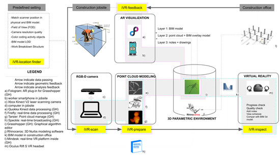
Figure 1.
System architecture for real-time information flow between construction offices and sites (near real-time monitoring of a single activity).
3.2.1. iVR-Location Finder Module
In addition to the predefined setting requirement list, this research developed a tool to aid inspectors to determine camera location before monitoring activity called iVR-location finder. This tool consists of a list of options to help the inspector control location of the scanning camera to monitor the targeted activity in the construction job-site in the planning stage of the proposed iVR system. These options are choosing a laser scanner type and brand from a drop-down list, select the date of target activity from this tool’s calendar—see Figure 2 (component 1)-, laser scanner field of view (FOV), visible and blocked angles, laser scanner camera view in BIM environment, laser scanner field of view window sphere. Once the inspector chooses the laser camera type and date, iVR location finder will generate an optimized FOV location. The optimized location is found by (a) dividing working area to equal isocurves where is construction activity daily working space-closed boundaries where is the day selected from the work-space breakdown structure schedule, (b) calculating arithmetic mean points of each isocurve, (c) connecting arithmetic mean points by an interpolated curve to generate activity area Center-line (), (d) divide by Camera Radius () divided by to generate a double amount of of cameras needed for , where k is greater than . In this research k is 2.01, which is half added amount of (0.01) to ensure that the camera FOV is covering all .
where is the radius of camera field of view and is number of needed for . After that, (e) Cull (remove) by True and False logic to divide by two and get optimized , and finally (f) draw FOV, and in the BIM model as shown in Figure 2 (component 3). All iVR-location finder process data that consist of FOV, and are overlaid in the BIM model. The physical location of the camera is synchronized with with the digital model manually to ensure an accurate overlay of as-built data with the as-planned data of BIM model in the iVR system.
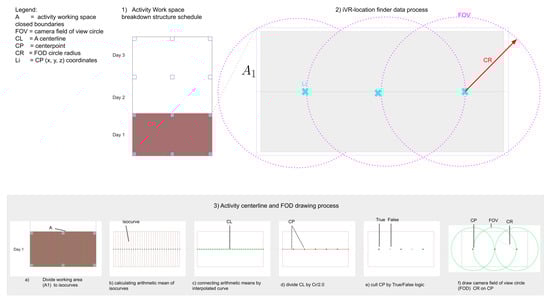
Figure 2.
iVR-Location finder module data process used to optimize camera location in the predefined set of iVR system.
3.2.2. iVR-Scan Module
Therein phase, a laser scanner is placed on the job-site to monitor a specific activity and send live scanning data to the construction office. The location, direction, type of laser scanner, software, and hardware required to accomplish successful scanning this are the primary focus of this phase as illustrated in Figure 3. The coordinates and 3D model of the construction site need to be recorded and registered in the BIM environment in advance. Subsequently, the inspector defines a clear visible location for the laser scanner called iVR-location finder.
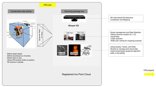
Figure 3.
iVR-scan module system architecture and data sending process from site to office.
The scanning duration depends on the following variables: (1) importance of activity: the number of times the activity needs to be monitored by project engineer; (2) daily working hours: start and end times of daily work; (3) activity location: whether the activity is conducted indoors or outdoors; and (4) scale of target objects. Therefore, the inspector should determine the duration of scanning during the planning stage of the activity, especially in the design-build delivery method, where activity implementation occurs at a faster rate, as compared to that in other delivery methods. Laser scanners can be divided into two types of hardware. The first type is stand-alone laser scanners, which are mobile and can store and transfer data to the computer after the completion of the scanning process. The second type is live scanning devices, which need to be connected to a computer during the scanning process to transfer data in real-time. This study considers the second type of scanner to reduce the gap between scanning and data processing. However, such scanners are difficult to implement in construction sites, as they require a power source and large amounts of space; these scanners have also limited mobility compared with portable scanners. Before choosing a monitoring system, utility, time efficiency, accuracy, level of automation, required preparation, training requirements, cost, and mobility of existing progress monitoring were evaluated in the literature review and analyzed. The research chose Kinect V2 as the 3D laser scanner because it offers live scanning (LIDAR + photogrammetry = Kinect 3D scan). The research component is built on a combination of cameras and sensors for target observation and distance recognition. The process of scanning the target object is as follows: (1) set up a monitoring camera in the construction site and direct it toward the target object following of iVR-location finder; and (2) connect Kinect V2 to the PC Grasshopper graphical algorithm editor incorporated with the commercially developed Rhinoceros software. Three point cloud libraries are used to manage the point cloud data and convert them into the point, color, and GPS coordinates, to process the produced model in real-time as depicted in Figure 3. The registered point cloud in the iVR-scan is then passed to iVR-prepare to start converting the point cloud to 3D mesh geometry. iVR-scan set up a timer to release live frames of point cloud every 100 ms and pass it to the next module to control data processing and computation.
3.2.3. iVR-Prepare Module
The iVR-prepare receives point cloud data from iVR-scan every 100 Milliseconds (ms) time-lapse. This module filters the point cloud converts it to a 3D mesh model and sends it to iVR-inspect using custom cloud based data transfer. The iVR-prepare algorithm processes received point cloud data from iVR-scan and process is as follows: (a) iVR-prepare received point cloud data and RGB-D images from IVR-scan every 100 ms; (b) The inspector sets the target object boundary and uses iVR-prepare to crop the targeted object from the scanned scene using color coding to reduce computational data and time required for subsequent steps; (c) iVR-scan erases all geometries located outside the targeted bounding box set prior by the inspector and keeps only point cloud data located inside it; (d) This module creates a uniform voxel grid structure to initiate 3D mesh object from point cloud; (e) iVR-prepare employs mesh marching mathematical logic and ball-pivoting algorithm (BPA) to convert the point cloud into a 3D mesh object; (f) iVR-prepare employs a bounding box to surround the produced 3D mesh to reduce computational data and time. (g) iVR-prepare sends the final 3D mesh geometry from construction job-site PC to office PC using Speckle cloud as depicted in Figure 4.
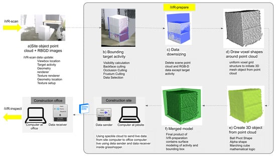
Figure 4.
The system architecture of iVR-prepare module; (a) Point cloud data received from iVR-scan in job-site; (b) Bounding box covering target activity; (c) Cropping target activity point cloud and removing rest of scene data; (d) Voxel shape around point cloud to detect neighboring points; (e) generating 3D mesh geometry from the point cloud using bull pivot; (f) Merging 3D mesh geometry and bounding box.
This study uses BPA to reconstruct a mesh from a point cloud. This logic employs a sphere to roll across the “surface” of the point cloud . The sphere scale is slightly larger than the distance between two points, to cover them inside its boundary. This sphere begins from two points and starts rolling to include additional points to generate the outer shell of the mesh. The sphere is rolled and pivoted along the edge of the triangle-shaped between two lines. After that, the ball settles at a new location; a new triangle is created from two previous vertices and a new point is attached to the mesh, forming the expansion triangle. As the sphere continues to roll and rotate, additional triangles are shaped and connected to the mesh. The sphere continues this motion until the mesh is completely shaped as shown in Figure 5.
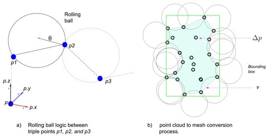
Figure 5.
Illustration of BPA and generation of closed-mesh objects from the point cloud.
The subsequent sections present a 2D BPA visualization, wherein a sphere settles among pairs of points. The two points are connected each time the sphere settles to fill in the mesh. In 3D cases, the sphere is connected among three points as shown in Figure 5.
The sphere radius, , is obtained empirically based on the size and scale of the input point cloud:
The average distance among neighboring triple points, , is divided by 2 to obtain the radius of the sphere and then increased by multiplying it with (1.05–1.25) to ensure that includes within its boundaries. All points need to be obtained within a distance of from the starting point p. To control the variance of between neighboring points, we use the voxel cube data structure. This cube has a side length of . Voxel location coordinate of a given position p with coordinates is a triplet:
To populate the voxel on , the above-mentioned equation is developed to fit the visual algorithm developed in iVR-prepare. For a point in , the x coordinate is subtracted from the voxel corner point x coordinates and divided by (similarly for ). The generated voxel of the outer shell of the mesh is then relaxed to produce a smooth surface as depicted in Figure 5.
iVR-prepare conducts an empirical analysis of the mesh produced from the point cloud and compares it with the BIM model to calculate the progress rate and quantify the achievement during that activity as shown in Figure 4 ( component d and f). Besides, iVR-prepare stores the progress data in a report and attaches it to iVR- feedback for AR visualization. Besides, the developed visual algorithm provides an option to the QA inspector to download the progress data to the local machine in Excel format.
The iVR-prepare is limited to indoor construction activities that contain one object or multiple objects and can be monitored by the field of view of a Kinect camera. It converts targeted object-captured point clouds to a light size 3d mesh and sends it to the construction office. After that, speckle cloud is used to transfer the point cloud data from the job-site to the construction office. Subsequently, the Grasshopper and Rhinoceros algorithms synchronize and update the point cloud for each period.
3.2.4. iVR-Inspect Module
In this module, the 3D mesh is received from job-site iVR-prepare using Speckle cloud data receiver. The 3D mesh generated in the iVR-prepare phase is aligned with the BIM model. The Kinect camera and 3D model in the construction job-site physical site and construction office are aligned in the predefined setting. The project engineer connects the VR headset to the Rhinoceros environment and begins inspecting the progress data received from the job-site in VR.
Generally, iVR-inspect proceeds as follows: (1) Align the 3D mesh built-in iVR-prepare with the BIM model; (2) connect a VR headset to the immersive reality and set up the quality, scale, and colors of different models; (3) Project engineer monitors the progress, building accuracy and quality check; (4)The inspector uses VR inspection tools provided by Mindesk in the virtual reality mode that include writing comments, highlights objects, taking measurements, comparing BIM model to the progress model received from iVR-prepare and provides illustrations as feedback; and (5) the iVR-inspect sends the monitoring report that includes (comments, drawings, and geometry) to iVR-feedback as illustrated in Figure 5.
This study employed the VR inspection method and BIM, instead of conventional site visits and point cloud screen checking, to award project engineer with the advantages of an immersive reality, thereby improving inspection rate, speed, and accuracy as well as the virtual feeling of being present in a job-site even when sitting in a construction office as illustrated in Figure 5. This study employs the Mindesk package of Grasshopper to control the iVR-inspection module. Mindesk comes with apart from Grasshopper, which allows your parametric model in the space of VR. 3D CAD models immersed in VR can be built, edited, and navigated without exporting the Rhino project by using this package. The current tools used in iVR-inspection include 3D navigation, multi-scale view, geometric editing, NURBS editing, surface modeling, curve modeling, text tagging, and note drawing. Mindesk functions with HTC Vive™, Oculus Rift™, and Windows Mixed Reality™ devices. It can also incorporate AR into the same platform; however, in this study, we only focus on its VR-related aspects.
After performing progress and progress checks, the project engineer provides illustrations, and adds comments, iVR-inspect sends the multilayer data, including the BIM model, overlaid model, comments and illustrations, and accomplishment report, to iVR-feedback as depicted in Figure 6.
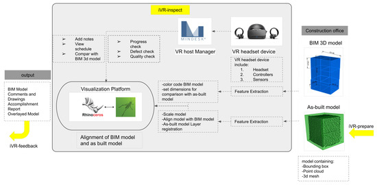
Figure 6.
The system architecture of iVR-inspection module illustrating inspecting work progress using virtual reality in the construction office.
3.2.5. iVR-Feedback Module
iVR-feedback focuses on visualizing the engineer’s reports using mixed reality in job-site by utilizing augmented reality application that synchronize BIM model in construction office with worker smart phone in real time. The workflow of iVR-feedback includes the following steps: (1) The worker phone is registered with the construction office’s Fologram tool to receive live data; (2) engineer sends the BIM model, comments and illustrations, accomplishment report, and overlaid model via the Fologram to job-site’s cell phone; and (3) job-site worker visualizes all received data in mixed reality using the cell phone as illustrated in Figure 7.
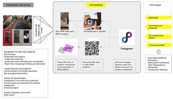
Figure 7.
The system architecture of the iVR-feedback module.
An immersive holographic instruction set is generated using parametric models representing the architecture. Fologram, which is included in Rhino and Grasshopper text, synchronizes the geometry with that developed in mixed reality devices linked via a local Wi-Fi network. If a consumer makes improvements to a pattern in Rhino or Grasshopper, these modifications are observed and transmitted to all linked mixed reality apps. Using familiar and efficient desktop CAD tools, the users can view digital models in a physical setting and on a scale when making improvements to such models. The placement of the 3D model is controlled by placing a QR code in the Rhinoceros canvas in the construction office and a corresponding code in the job-site. Once workers receive the data, they can visualize the QA inspector’s comments and overlaid the model in a near real-time manner. This system requires that the worker phone is registered in the construction office’s Fologram tool and both the construction office and job-site mobile phones need to be connected to the same Wi-Fi. As a result, engineer and job-site workers function synchronously and can receive and send near real-time data between job-site and construction sites using extended reality and 3D scanners associated with visual programming algorithms as shown in Figure 7.
3.3. Data Management
To address the application interoperability issue, primarily induced by discrepancies in the application format, this paper proposes using the Rhinoceros platform and the (.3dm) format as a unified data format between different software and hardware. The entire hardware is directly connected to the Rhinoceros modeling platform and then synchronized using the speckle cloud-based data-sharing. In job-site, Kinect V2 is connected to Grasshopper and Rhinoceros, and its point cloud data and resolution parameters are managed and stored in it. Subsequently, all the captured point cloud data are sent to the construction office’s Grasshopper and Rhinoceros using the speckle cloud tool, which maintains the synchronized and updated models in both computers. After that, the inspector assesses progress and associates the report with the model. Finally, the feedback data are sent back to the job-site cell phone using the AR synced with the office BIM model.
4. Case Study
To validate the feasibility of the proposed iVR system, a lab test is conducted to simulate a specific work inspection between the job-site and the construction office. Two case studies were built to test iVR. The first case study is column-finishing material monitoring activity and the second case study is HVAC pipe installation monitoring activity.
4.1. Case Study 1: Column Finishing Material Activity Monitoring
The first case study consists of a grid of 4 m × 4 m concrete columns with 0.4 m length × 0.4 m width. Concrete columns are designed in a BIM environment and represented by Styrofoam boxes in the lab to resemble a job-site. Before starting the work inspection experiment, an iVR-location finder was used to optimize the Kinect camera location. After that, all four phases of iVR were implemented, and the time consumed, accuracy, and practicality of these junctures are recorded for further development of the system. In this phase, a laser scanner is placed within the range of the target object (concrete columns) using an iVR-location finder, and the coordinates of its focal point are registered, for synchronization with its corresponding location in the BIM environment. In this case study, Kinect V2 is chosen from the list of 3D scanners. The user can choose the optimal scanner location based on various essential parameters, including the type of laser scanner, duration of the activity, work schedule, breakdown structure, field-of-view of the scanner, visible angles, blocked angles, perspective viewpoint of the scanner in the BIM model, and working window sphere of the scanner, as illustrated in Figure 8. Kinect V2 chosen in this case study parameters embedded in the iVR-location finder tool are outlined in Table 2. The Kinect V2 used in this case study has a horizontal range of 0.3–4500 mm, and therefore, one laser scanner location can cover two columns (Figure 8); the laser scanner’s field-of-view window sphere component in each direction is at 292°.
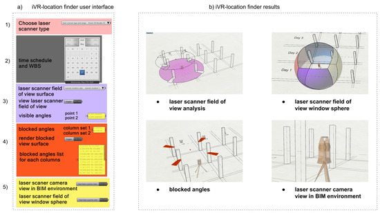
Figure 8.
iVR-location finder’s user interface and implementation in the case study of column finishing material construction; (a) user interface of iVR-location finder including scanner location finder parameters; (b) iVR-location finder possible results depending on the case study.
Table 2.
Technical specification of the Kinect sensor used in a case study.
The first case study targets monitoring finish work of column elements. The column structure consists of 12 columns distributed in 4 by 3 with 4 m by 4 m span and 0.4 m by 0.4 m cross-section as shown in Figure 9 (component a). The case study was built in the lab monitoring one column and placing the Kinect camera in the physical position corresponding to the digital position generated using iVR-location finder as shown in Figure 9 (component b). As part of predefined settings. iVR-location finder is used to generate a camera position in the digital model. The results of iVR-location finder are day one of work breakdown structure needed 4 3d scanners in the job-site to monitor 6 targeted columns, a field of view of the camera is 297 degrees, blocked fields of view are 63 degrees and laser camera view in the BIM environment as illustrated in Figure 9 (component c).
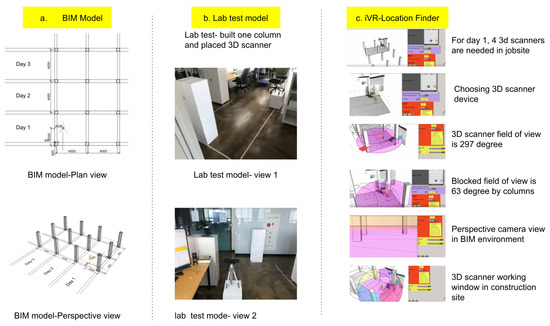
Figure 9.
Case study detailed maps and 3d model + 3D scanner location: (a) virtual BIM model of column structure consist of 12 columns 4 m by 4 m span and 0.4 by 0.4 m cross-section; (b) Lab test physical model representing 3D scanner, targeted activity ( one column), and building boundary lines; (c) iVR-location finder tool used to optimize 3D scanner locations in a virtual case study.
Lab experiment work was divided into five stages in correspondence with iVR system modules: first stage covers iVR-location finder, second stage covers iVR-scan, third stage covers iVR-prepare, fourth stage covers iVR-inspect, and final stage covers iVR-feedback. First, In the case study, the lab test is commenced by targeting one column for 3D laser scanning, capturing 3D geometry vertices, and registering the point cloud using Kinect V2 (Seconds Time). Qualla library is operated to conduct the resolution of the point clouds and manage computational data processing and the time required. Subsequently, a cropping box is built to include only the targeted objects (concrete columns for this case study) for the next step, to reduce computational time, and to exclude unnecessary objects scanned from the point cloud as described in Figure 9.
Second, the iVR-prepare registers point clouds in each interval and updates the existing point clouds as a loop. In this case study, the interval for updating existing point clouds is set to 15 min. As stated in the Methodology section, iVR-prepare converts the concrete column point clouds into a 3D mesh by using PVA. Thereafter, the 3D mesh and point cloud are sent to the construction office using a speckle cloud 3D model synchronizing tool and overlaid with the BIM model through the Grasshopper and Rhinoceros software. Third, In the construction office, the project engineer receives the point cloud and 3D mesh data using the speckle data receiver tool of Grasshopper and Rhinoceros. This study uses Oculus rift S for iVR-inspection. Inspector begins visualizing the 3D model through an immersive VR, taking measurements, writing notes, checking progress, assessing quality, acquiring snapshots of necessary details, and generating work inspection reports. Fourth, the algorithm developed by iVR-feedback lunches the inspector’s report back to the job-site using the Fologram AR tool of Grasshopper and Rhinoceros. Workers on job-site receive work inspection reports, which include the BIM model, comments and drawings, accomplishment rate, and overlaid model. It should be noted that external data can also be attached to progress monitoring reports; these data include site location work-space, task independence, schedules, and construction methods. For the AR to function appropriately, the worker’s phone should be registered in the Fologram tool in the office, and both devices should connect to the same WiFi network. In this case study, iVR-feedback successfully visualizes the feedback data in the construction site and the worker can view the inspector’s comments and the overlaid model and follow the necessary updated information recommended by the inspector without any physical interactions as described in Figure 10.
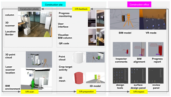
Figure 10.
Column lab test case study for work inspection using the iVR system all phases.
Changes in the mixed reality are introduced in models by associating the observed movement behaviors parametrically with the framework generated on the device. In an event-based parametric modeling interface, Buttons are created and placed in the substantial space adjacent to the construction site; these buttons can increase or decrease the current course of finishing material tiles in covering of columns without using BIM environmental show in Figure 10. The columns in the design model were clustered into courses to allow building stages to display each course as needed separately and to avoid unbuilt areas of the plan causing visual disturbances during development.
To accomplish one loop of the data process in iVR, the time needed, precision and the file size was monitored and quantified to check how the hidden layers of this system work. Before starting the case study, some parameters were fixed including target activity at job-site is selected, a 3D scanner is installed on-site and connected to site computer, office computer and site computer are connected to same wifi ID and speckle cloud ID, VR is set up and ready to use, worker mobile phone ID is registered in-office computer, and QR code in BIM model and job-site is generated, placed, and synchronized in one benchmark.
Table 3 outlines the details of the time needed to finish one loop of iVR system. To measure the pure data computational time, Table 3 excluded location finding, inspector’s comments, worker feedback time because it is variable dependent on person and activity nature. Data process time needed to finish one loop of iVR for one concrete column take place nearly 17 min, and the total time demanded to finish one loop including inspector commenting in VR, worker visualizing in AR, and iVR-location finder for the case study was nearly 40 min. Time calculated in this table is mathematically related to the computational power of the device, internet speed, data size, and activity nature. Therefore, it is a effective practice to calculate how much time a loop in iVR will take before an activity progress monitoring starts.
Table 3.
Data exchange time gap and parameters to complete one loop of the case study of iVR.
4.2. Case Study 2: HVAC Pipe Installation Activity Monitoring
In this case study, an HVAC pipe installation activity was targeted to examine the proposed system. Using iVR, inspectors can inspect HVAC pipes hanging on the ceiling easily and perceive them from a variety of angles in different scales that are difficult to do in a real job-site. Therefore, case study 2 is important to check the advantages of the proposed study. The Kinect camera location was generated using iVR-location finder and directed toward target activity as shown in Figure 11. Next, the camera started generating point clouds of the targeted HVAC pipes and surrounding objects including the wall, ceiling, and partition window. Then iVR-preparation converted the point cloud into a 3d model as shown in Figure 11. After that, the inspector could view HVAC pipes from peculiar angles that are hard to view on the job-site. iVR-inspect of HVAC pipe activity lets the inspector view the 3D model generated from the site and compare it to the BIM model while sitting in the construction office using a virtual reality tool. The inspector checks defects, the inspector writes comments, takes screenshots, checks measurements, and coordinates and views the model from different scales and angles. Finally, the iVR-feedback enables the worker in the job-site to view the inspector report in AR mode. One loop of data processing in iVR in case 2 took 11 min to complete as illustrated in Figure 12.
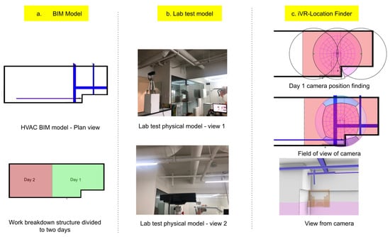
Figure 11.
A case study in the digital and physical model: (a) BIM model of HVAC pipe installation activity and space WBS divided into day 1 and 2; (b) Lab test physical model representing 3D scanner, targeted activity (HVAC pipe installation); (c) iVR-location finder tool used to optimize 3D scanner locations in a virtual case study.
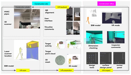
Figure 12.
case study for HVAC pipe work inspection using the iVR system all phases.
5. Discussion
This research starts with an inspection checklist and predefined setting that include synchronizing physical and digital models, setting the field of view, laser scanner resolution, and illumination, BIM model level of details, and work breakdown structure. In addition to the predefined setting, iVR-location finder aids the inspector to optimize the laser scanner device’s position using a user interface developed list that controls scanner selection, WBS data, and visualize the field of view of the laser scanner in the predefined setting before monitoring activity starting. The inspector positions the laser scanner in the exact position generated using the iVR-location finder and synchronizes its field of view both in the physical and digital model. The iVR monitoring system starts when iVR-scan registers point cloud data every 100 ms and send it to iVR-prepare on the construction site. Next iVR-prepare converts point cloud data into a 3D mesh using marching machine techniques and send generated geometry from the construction site to the construction office using Speckle cloud. After that, iVR-insect receives 3D mesh geometry from the construction site and the inspector views it exploiting a virtual environment by utilizing the Mindesk plugin. The inspector compares received an as-built model from job-site with an as-planned model in the office, check the quality, measures work progress, write comments, draw sketches, takes snapshots of specific areas and details that need to be taken care of by the worker packs it while in the virtual reality mode and send it to the iVR-feedback. Finally, the worker received an inspection report on his smartphone, uses the augmented reality of the iVR-feedback module to view it, and follow instructions written in it. The relationship between all iVR modules and data passing is tested in two case studies and delivered expected results successfully.
The results of this research include recording the timing, data transfer between modules and significant findings of each case study. The time needed finishing one loop of iVR data passing was about 17 min and the total case study needed about 40 min including the inspector writing comments and comparing BIM and the built model and the worker viewing the inspection report in augmented reality mode. The iVR-location finder targeted one column and optimized the best laser scanner location and passed location coordinates data to iVR-scan which captures point cloud and passes it to iVR-prepare. The iVR-prepare can convert point cloud data to voxel structure (low-resolution light model with rough surface and low thickness accuracy) and mesh format (the high precision model that takes a long time to generate). 3D mesh geometry data transfer from a construction site to an office is limited to small objects only and cannot handle big size geometries like a complete building.
The result of the case study on monitoring the progress of concrete columns and HVAC revealed that the proposed system can support more advanced and comprehensive activities in construction job sites. The developed iVR system successfully registered monitoring data, processed these data and enabled the inspector to generate a report and send it back to the construction job-site as feedback. In iVR- inspection, the inspector can employ VR to view concrete columns and HVAC pipes from different angles and obtain measurements that would not be possible when using conventional monitoring processes. This study argues that the use of iVR can improve decision-making in the work inspection stage and result in a better construction product in a shorter time, with limited human involvement. Moreover, this method reduces physical interactions, which helps maintain social distancing and prevents the spread of the current health pandemic.
By exploiting the advantages of VR, the inspector can orbit around the target activity, obtain measurements, magnify the structure (1/1 scale or closer), locate areas, and observe precise existing and future conditions. Besides, difficult situations to access in real life, such as the space between a false ceiling and the ceiling beams, can be monitored using this system. However, digital models may not present all the required information; thus, onsite verification needs to be performed remotely. Once onsite dimensions are verified, they can be used to inform and guide project engineers regarding future steps. Owing to the simple parametric setup of a Grasshopper environment, design engineers can adjust the capacity, size, and location of each system quickly and effortlessly. This process also enables the design engineer or the project manager to access the model, thereby facilitating collaboration between them; thus, a global model that all disciplines can observe and contribute to. This workflow can be extremely helpful for projects that require the deployment of prefabricated components as soon as they arrive, such as double-supported frame walls that occupy more space than normal.
In general, This system contributes to the automation and sustainability in the construction monitoring by reducing manpower that reduces inspection cost and logistics since the inspector is sitting in the office, remotely inspecting indoor activity without needing to examine the site personally. The innovative methods, algorithms, and technologies developed in this study distinguish it from previous research. In general, the iVR system integrates point cloud capturing devices with extended reality (VR and AR) technology for remote construction indoor activities into one platform. The most important contributions of this study are as follows: First, in this study, a 3D laser scanner is directly connected to the BIM environment and captures point cloud data inside the iVR system platform, which does not need a medium platform to handle or send point cloud data between other software. However, as the literature review stated, most current best practice work inspection requires a medium platform to convert the scanned data into point cloud or massing geometry.
Second, the iVR system eliminates file format compatibility issues, as all hardware and software are connected directly to the graphical algorithm editor of Grasshopper that this system is hosted on inside Rhinoceros3D commercially developed software. In contrast, other progress-monitoring methods mentioned in the literature review involves different scanning devices with various formats (XYZ, ply, pts, e57, las, and laz) and BIM formats (.3dm, .dwg,.obj, .ifc, .rvt, and .nwd), which result in incompatibility issues. This might even cause distortion, loss of data, and time-consuming due to the use of different versions of data processing.
Third, this system contributes to creating a healthy monitoring environment by minimizing physical interaction between workers and inspections in the job-site by proposing remote construction monitoring from the construction office without needing to be physically in the construction job-site. The time gap between the live data capturing in the construction site and construction office is about 17 min which might be impractical for intense activities like installing sensors, CCTV cameras, and pouring fast hardening materials onsite that need monitoring in live time but this time gap is good for other ordinary indoor activities.
Fourth, in iVR, data storage is managed and controlled within the BIM environment. Kinect devices, VR headset, and Fologram are attached to the BIM environment to import/export data, resulting in a lightweight and rapid system. However, in other state-of-the-art progress-monitoring approaches, data is stored on the cloud of the scanner’s manufacturer or portable devices; this is impractical because the user needs to connect all stored point cloud data to another data cloud or BIM software to monitor activity progress. Besides commercially developed construction progress tools builds as-built model by personally visiting the job-site and capture data manually then process it which take more than 24 h before being ready for inspection while in iVR the system updates the as-built model automatically in near real-time (every 17 min) as shown in Table 4.
Table 4.
comparing iVR system to the recent advanced commercially developed construction progress monitoring tools.
The applied research is deprived of some limitations; for instance, all data needs to be readily available to feed into the system prior to iVR to start performing. Next, in iVR-inspect module, data overload accrues occasionally while using virtual reality mood for inspection which causes the system to crash. Therefore, it is advised to reduce BIM model details before overlaying it with as built model inside VR environment to prevent data overload.
In addition, the iVR-scan module’s point cloud capturing device contains limitations in scanning highly reflective items, such as mirrors and highly polished surfaces; transparent items, such as glass and liquids; and items that refract and reflect light, like number plates and clothing reflective panels. Nevertheless, objects that typically do not reflect light may do so under certain conditions (such as the paint coating of cars and stainless steel); hence, additional scans will be required to obtain sufficient information regarding such objects. Besides, iVR-scan module works well in the indoor data acquisition but does not perform well in the outdoor environment due to strong sunlight lamination therefore iVR-scan can replace kinect device with other data capturing devices easily for outdoor monitoring purposes because it is built using visual programming which makes iVR-scan host different data capturing devices with a minor change in the code.
Moreover, each iVR module has certain input and output requirements to perform correctly. Therefore in case some data is not available or corrupted, the system will not work properly and the inspector needs to debug the problem. Finally, In this research, iVR-prepare target indoor activities that contain small objects that can be observed by the field of view of one Kinect camera and convert its captured point cloud to 3d mesh. Therefore point cloud density and geometry quality need be optimized and set prior to the monitoring stage to prevent data overload that might cause failure in data transfer between job-site and office. Therefore iVR-prepare works best when it transfer geometry data of objects inside activities like column finish work and HVAC pipe successfully from jobsite to office but it is unable to handle big geometry data like a full building or multiple workspaces at the same time and it needs to be separated to separate monitoring stations to prevent data overload.
6. Conclusions
Although there have been significant developments in 3D scanning and photogrammetry technologies for construction work inspection, existing progress tracking methods still require manual intervention or data processing. This significantly increases the time required for monitoring and relies on conventional methods. To address this issue, we developed and tested a near real-time construction project monitoring tool (iVR). Based on the findings, the significant benefits of iVR are as follows:
- The results indicate that the developed tool amplifies the potential to bridge the gap between the construction office and job-site by only capturing the necessary data and exchanging it to decrease computational complexity and time consumption.
- Immersive virtual and AR helps the inspector and workers to visualize the activity from different angles, which cannot be achieved via conventional methods, and provides the necessary tools for drawing, commenting, attaching data, and communicating faster without requiring physical interactions.
- Using iVR, inspectors can monitor various activities quickly without physically leaving the construction office. This can have valuable implications on the nature of work inspection, reduce human resources, increase automation in monitoring activity and increase quality and production which will reduce monitoring cost.
- Another contribution of the proposed approach is that it facilitates social distancing and reduces physical interaction between workers and the construction officer; this is expected to help curb the spread of the current pandemic and create healthier and safer environment in construction site.
In summary, the significant potential of iVR in work inspection at the construction stage was ascertained and confirmed using a lab case study. In the future, this tool can be developed as a tab plug-in to commercial software applications, thereby enhancing the entire inspection process. However, the architecture of the present methodology is limited to the geometry of the activity, such as built-in work inspection.
Hence, subsequent works should aim to expand the proposed model to include progress tracking (photogrammetry + real 3D scanner), material tracking (GPS and RFID), worker tracking (RFID), and equipment tracking (GPS and distributed sensors). iVR-scan only scans a job-site target activity; hence, it should be extended to focus on object quality assessments, human activities, as well as human recognition and skeletonizing, for identifying human figures and tracking the skeleton images of people moving within the Kinect field of view. In the future, this system will be implemented and tested on actual construction sites to elucidate the potential advantages and challenges of this system. Moreover, it is anticipated that iVR can become a communication platform between QAQC Engineer, Owner, and General Contractor during the construction stage of the project by utilizing extended reality integrated with 3D laser scanning to increase automation and efficiency as a key toward sustainability in construction. Furthermore, in iVR-prepare, the generated reports can be integrated with the targeted activity reports of the BIM schedule and provide feedback for the self-update of the 4D BIM, thereby enhancing automation in QA inspection.
Author Contributions
Conceptualization, A.K.A. and C.P.; methodology, O.J.L.; software, A.K.A.; validation, C.P., D.L.; formal analysis, C.P.; investigation, O.J.L.; resources, O.J.L.; data curation, C.P.; writing–original draft preparation, A.K.A.; writing–review and editing, C.P.; visualization, A.K.A.; supervision, C.P.; project administration, O.J.L.; funding acquisition, O.J.L. All authors have read and agreed to the published version of the manuscript.
Funding
This research was funded by the Korea Agency for Infrastructure Technology Advancement (KAIA) grant funded by the Ministry of Land, Infrastructure, and Transport (Grant 20SMIP-A158708-01). This research was also supported by Haenglim Architecture and Engineering Company. The first author would like to thank Chung Ang University and the Korean Government Scholarship program.
Institutional Review Board Statement
Not applicable.
Informed Consent Statement
Not applicable.
Data Availability Statement
The data used in this research is available in Mendeley Data to help researchers reproduce the results of this research following this link (http://dx.doi.org/10.17632/g2xh9k5yzy.2).
Acknowledgments
This work is supported by the Korea Agency for Infrastructure Technology Advancement (KAIA) grant funded by the Ministry of Land, Infrastructure, and Transport (Grant 20SMIP-A158708-01). This research was also supported by Haenglim Architecture and Engineering Company. The first author would like to thank Chung Ang University and the Korean Government Scholarship program.
Conflicts of Interest
The authors declare no conflict of interest.
References
- Forcael, E.; Ferrari, I.; Opazo-Vega, A.; Pulido-Arcas, J.A. Construction 4.0: A Literature Review. Sustainability 2020, 12, 9755. [Google Scholar] [CrossRef]
- Alizadehsalehi, S.; Yitmen, I. A concept for automated construction progress monitoring: Technologies adoption for benchmarking project performance control. Arab. J. Sci. Eng. 2019, 44, 4993–5008. [Google Scholar] [CrossRef]
- Braun, A.; Tuttas, S.; Borrmann, A.; Stilla, U. Improving progress monitoring by fusing point clouds, semantic data and computer vision. Autom. Constr. 2020, 116, 103210. [Google Scholar] [CrossRef]
- Kim, S.; Kim, S.; Lee, D.E. Sustainable Application of Hybrid Point Cloud and BIM Method for Tracking Construction Progress. Sustainability 2020, 12, 4106. [Google Scholar] [CrossRef]
- Shen, W.; Shen, Q.; Sun, Q. Building Information Modeling-based user activity simulation and evaluation method for improving designer–user communications. Autom. Constr. 2012, 21, 148–160. [Google Scholar] [CrossRef]
- Srour, I.M.; Abdul-Malak, M.A.U.; Yassine, A.A.; Ramadan, M. A methodology for scheduling overlapped design activities based on dependency information. Autom. Constr. 2013, 29, 1–11. [Google Scholar] [CrossRef]
- Chi, S.; Caldas, C.H. Image-based safety assessment: Automated spatial safety risk identification of earthmoving and surface mining activities. J. Constr. Eng. Manag. 2012, 138, 341–351. [Google Scholar] [CrossRef]
- Parhi, D.R.; Choudhury, S. Analysis of smart crack detection methodologies in various structures. J. Eng. Technol. Res. 2011, 3, 139–147. [Google Scholar]
- Mahami, H.; Nasirzadeh, F.; Hosseininaveh Ahmadabadian, A.; Nahavandi, S. Automated progress controlling and monitoring using daily site images and building information modelling. Buildings 2019, 9, 70. [Google Scholar] [CrossRef]
- Scott, S.; Assadi, S. A survey of the site records kept by construction supervisors. Constr. Manag. Econ. 1999, 17, 375–382. [Google Scholar] [CrossRef]
- Pučko, Z.; Šuman, N.; Rebolj, D. Automated continuous construction progress monitoring using multiple workplace real time 3D scans. Adv. Eng. Inform. 2018, 38, 27–40. [Google Scholar] [CrossRef]
- Azhar, S.; Ahmad, I.; Sein, M.K. Action research as a proactive research method for construction engineering and management. J. Constr. Eng. Manag. 2010, 136, 87–98. [Google Scholar] [CrossRef]
- Assaad, R.; El-adaway, I.H.; El Hakea, A.H.; Parker, M.J.; Henderson, T.I.; Salvo, C.R.; Ahmed, M.O. Contractual Perspective for BIM Utilization in US Construction Projects. J. Constr. Eng. Manag. 2020, 146, 04020128. [Google Scholar] [CrossRef]
- Albert, A.; Hallowell, M.R.; Kleiner, B.; Chen, A.; Golparvar-Fard, M. Enhancing construction hazard recognition with high-fidelity augmented virtuality. J. Constr. Eng. Manag. 2014, 140, 04014024. [Google Scholar] [CrossRef]
- Porwal, A.; Hewage, K.N. Building Information Modeling (BIM) partnering framework for public construction projects. Autom. Constr. 2013, 31, 204–214. [Google Scholar] [CrossRef]
- Xu, J.; Ding, L.; Love, P.E. Digital reproduction of historical building ornamental components: From 3D scanning to 3D printing. Autom. Constr. 2017, 76, 85–96. [Google Scholar] [CrossRef]
- Jin, R.; Zuo, J.; Hong, J. Scientometric review of articles published in ASCE’s journal of construction engineering and management from 2000 to 2018. J. Constr. Eng. Manag. 2019, 145, 06019001. [Google Scholar] [CrossRef]
- Ali, A.K.; Lee, O.J.; Park, C. Near Real-Time Monitoring of Construction Progress: Integration of Extended Reality and Kinect V2. In Proceedings of the 37th International Symposium on Automation and Robotics in Construction (ISARC), Kitakyushu, Japan, 27–28 October 2020; pp. 24–31. [Google Scholar] [CrossRef]
- Riveiro, B.; Lourenço, P.B.; Oliveira, D.V.; González-Jorge, H.; Arias, P. Automatic morphologic analysis of quasi-periodic masonry walls from LiDAR. Comput. Aided Civ. Infrastruct. Eng. 2016, 31, 305–319. [Google Scholar] [CrossRef]
- Freimuth, H.; König, M. A framework for automated acquisition and processing of As-built data with autonomous unmanned aerial vehicles. Sensors 2019, 19, 4513. [Google Scholar] [CrossRef]
- Liu, J.; Li, D.; Feng, L.; Liu, P.; Wu, W. Towards Automatic Segmentation and Recognition of Multiple Precast Concrete Elements in Outdoor Laser Scan Data. Remote Sens. 2019, 11, 1383. [Google Scholar] [CrossRef]
- Kim, D.; Kwon, S.; Cho, C.S.; García de Soto, B.; Moon, D. Automatic Space Analysis Using Laser Scanning and a 3D Grid: To Industrial Plant Facilities. Sustainability 2020, 12, 9087. [Google Scholar] [CrossRef]
- Weerasinghe, I.T.; Ruwanpura, J.Y.; Boyd, J.E.; Habib, A.F. Application of Microsoft Kinect sensor for tracking construction workers. In Proceedings of the Construction Research Congress 2012: Construction Challenges in a Flat World, West Lafayette, IN, USA, 21–23 May 2012; pp. 858–867. [Google Scholar]
- Ray, S.J.; Teizer, J. Real-time construction worker posture analysis for ergonomics training. Adv. Eng. Inform. 2012, 26, 439–455. [Google Scholar] [CrossRef]
- Ali, A.K.; Lee, O.J.; Song, H. Robot-based facade spatial assembly optimization. J. Build. Eng. 2020, 33, 101556. [Google Scholar] [CrossRef]
- Li, Y.; Liu, C. Applications of multirotor drone technologies in construction management. Int. J. Constr. Manag. 2019, 19, 401–412. [Google Scholar] [CrossRef]
- Kaneko, K.; Kaminaga, H.; Sakaguchi, T.; Kajita, S.; Morisawa, M.; Kumagai, I.; Kanehiro, F. Humanoid Robot HRP-5P: An electrically actuated humanoid robot with high-power and wide-range joints. IEEE Robot. Autom. Lett. 2019, 4, 1431–1438. [Google Scholar] [CrossRef]
- Rizo-Maestre, C.; González-Avilés, Á.; Galiano-Garrigós, A.; Andújar-Montoya, M.D.; Puchol-García, J.A. UAV BIM: Incorporation of Photogrammetric Techniques in Architectural Projects with Building Information Modeling versus Classical Work Processes. Remote Sens. 2020, 12, 2329. [Google Scholar] [CrossRef]
- Bellés, C.; Pla, F. A Kinect-Based System for 3D Reconstruction of Sewer Manholes. Comput. Aided Civ. Infrastruct. Eng. 2015, 30, 906–917. [Google Scholar] [CrossRef]
- Cheng, L.K.; Chieng, M.H.; Chieng, W.H. Measuring virtual experience in a three-dimensional virtual reality interactive simulator environment: A structural equation modeling approach. Virtual Real. 2014, 18, 173–188. [Google Scholar] [CrossRef]
- Kamat, V.R.; El-Tawil, S. Evaluation of augmented reality for rapid assessment of earthquake-induced building damage. J. Comput. Civ. Eng. 2007, 21, 303–310. [Google Scholar] [CrossRef]
- Shirazi, A.; Behzadan, A.H. Design and assessment of a mobile augmented reality-based information delivery tool for construction and civil engineering curriculum. J. Prof. Issues Eng. Educ. Pract. 2015, 141, 04014012. [Google Scholar] [CrossRef]
- Jo, B.W.; Lee, Y.S.; Kim, J.H.; Kim, D.K.; Choi, P.H. Proximity warning and excavator control system for prevention of collision accidents. Sustainability 2017, 9, 1488. [Google Scholar] [CrossRef]
- Cai, H.; Andoh, A.R.; Su, X.; Li, S. A boundary condition based algorithm for locating construction site objects using RFID and GPS. Adv. Eng. Inform. 2014, 28, 455–468. [Google Scholar] [CrossRef]
- Yang, K.; Aria, S.; Ahn, C.R.; Stentz, T.L. Automated detection of near-miss fall incidents in iron workers using inertial measurement units. In Proceedings of the Construction Research Congress 2014: Construction in a Global Network, Atlanta, GA, USA, 19–21 May 2014; pp. 935–944. [Google Scholar]
Publisher’s Note: MDPI stays neutral with regard to jurisdictional claims in published maps and institutional affiliations. |
© 2021 by the authors. Licensee MDPI, Basel, Switzerland. This article is an open access article distributed under the terms and conditions of the Creative Commons Attribution (CC BY) license (http://creativecommons.org/licenses/by/4.0/).