
Harvesting Waste Thermal Energy Using a Surface-Modified Carbon Fiber-Based Thermo-Electrochemical Cell

 ,
,  ,
,  ,
,  , ,
, ,  and
and 
Abstract
1. Introduction
2. Materials and Methods
2.1. Materials
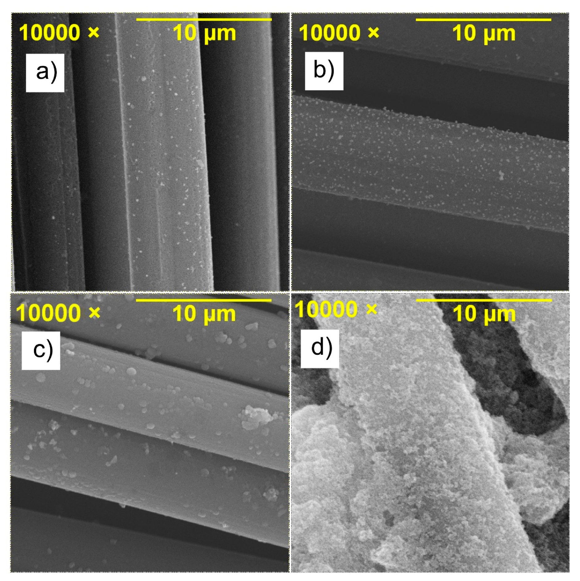
- Basic Busofit;
- Busofit with Ag magnetron sputtering;
- Busofit with Ti magnetron sputtering;
- Busofit with infiltrated dispersion of TiO2 nanoparticles.
2.2. Measurement and Characterization Technique
3. Results and Discussion
4. Conclusions
Supplementary Materials
Author Contributions
Funding
Institutional Review Board Statement
Informed Consent Statement
Data Availability Statement
Conflicts of Interest
References
- Im, H.; Kim, T.; Song, H.; Choi, J.; Park, J.S.; Ovalle-Robles, R.; Yang, H.D.; Kihm, K.D.; Baughman, R.H.; Lee, H.H.; et al. High-efficiency electrochemical thermal energy harvester using carbon nanotube aerogel sheet electrodes. Nat. Commun. 2016, 7, 10600. [Google Scholar] [CrossRef]
- Dupont, M.F.; Macfarlane, D.R.; Pringle, J. Thermo-electrochemical cells for waste heat harvesting—Progress and perspectives. Chem. Commun. 2017, 53, 6288–6302. [Google Scholar] [CrossRef]
- Burmistrov, I.; Kovyneva, N.; Gorshkov, N.; Gorokhovsky, A.; Durakov, A.; Artyukhov, D.; Kiselev, N. Development of new electrode materials for thermo-electrochemical cells for waste heat harvesting. Renew. Energy Focus 2019, 29, 42–48. [Google Scholar] [CrossRef]
- Zhang, L.; Kim, T.; Li, N.; Kang, T.J.; Chen, J.; Pringle, J.M.; Zhang, M.; Kazim, A.H.; Fang, S.; Haines, C.; et al. High Power Density Electrochemical Thermocells for Inexpensively Harvesting Low-Grade Thermal Energy. Adv. Mater. 2017, 29, 1605652. [Google Scholar] [CrossRef]
- Romano, M.S.; Li, N.; Antiohos, D.; Razal, J.M.; Nattestad, A.; Beirne, S.; Fang, S.; Chen, Y.; Jalili, R.; Wallace, G.G.; et al. Carbon Nanotube—Reduced Graphene Oxide Composites for Thermal Energy Harvesting Applications. Adv. Mater. 2013, 25, 6602–6606. [Google Scholar] [CrossRef]
- Zhou, Y.; Qian, W.; Huang, W.; Liu, B.; Lin, H.; Dong, C. Carbon Nanotube-Graphene Hybrid Electrodes with Enhanced Thermo-Electrochemical Cell Properties. Nanomaterials 2019, 9, 1450. [Google Scholar] [CrossRef]
- Hirai, T.; Shindo, K.; Ogata, T. Charge and Discharge Characteristics of Thermochargeable Galvanic Cells with an [Fe(CN)6]4−/[Fe(CN)6]3− Redox Couple. J. Electrochem. Soc. 1996, 143, 1305. [Google Scholar] [CrossRef]
- Artyukhov, D.; Kiselev, N.; Gorshkov, N.; Burmistrov, I. Research of the influence of electrolyte concentration on ther-mo-electrochemical cells efficiency. Proc. Environ. Sci. Eng. Manag. 2019, 6, 319–327. [Google Scholar]
- Duan, J.; Feng, G.; Yu, B.; Li, J.; Chen, M.; Yang, P.; Feng, J.; Liu, K.; Zhou, J. Aqueous thermogalvanic cells with a high Seebeck coefficient for low-grade heat harvest. Nat. Commun. 2018, 9, 1–8. [Google Scholar] [CrossRef]
- Hu, R.; Cola, B.A.; Haram, N.; Barisci, J.N.; Lee, S.; Stoughton, S.; Wallace, G.; Too, C.; Thomas, M.; Gestos, A.; et al. Harvesting Waste Thermal Energy Using a Carbon-Nanotube-Based Thermo-Electrochemical Cell. Nano Lett. 2010, 10, 838–846. [Google Scholar] [CrossRef]
- Salazar, P.F.; Kumar, S.; Cola, B.A. Design and optimization of thermo-electrochemical cells. J. Appl. Electrochem. 2013, 44, 325–336. [Google Scholar] [CrossRef]
- Wu, J.; Black, J.J.; Aldous, L. Thermoelectrochemistry using conventional and novel gelled electrolytes in heat-to-current thermocells. Electrochim. Acta 2017, 225, 482–492. [Google Scholar] [CrossRef]
- Zhou, H.; Liu, P. High Seebeck Coefficient Electrochemical Thermocells for Efficient Waste Heat Recovery. ACS Appl. Energy Mater. 2018, 1, 1424–1428. [Google Scholar] [CrossRef]
- Burmistrov, I.; Gorshkov, N.; Kovyneva, N.; Kolesnikov, E.; Khaidarov, B.; Karunakaran, G.; Cho, E.-B.; Kiselev, N.; Artyukhov, D.; Kuznetsov, D.; et al. High seebeck coefficient thermo-electrochemical cell using nickel hollow microspheres electrodes. Renew. Energy 2020, 157, 1–8. [Google Scholar] [CrossRef]
- Burmistrov, I.; Gorshkov, N.; Kiselev, N.; Artyukhov, D.; Kolesnikov, E.; Khaidarov, B.; Yudni, A.; Karunakaran, G.; Cho, E.-B.; Kuznetsov, D.; et al. Data on the current-voltage dependents of nickel hollow microspheres based thermo-electrochemical in alkaline electrolyte. Data Brief 2020, 31, 105770. [Google Scholar] [CrossRef]
- Gunawan, A.; Lin, C.-H.; Buttry, D.A.; Mujica, V.; Taylor, R.A.; Prasher, R.; Phelan, P. Liquid Thermoelectrics: Review of Recent and Limited New Data of Thermogalvanic Cell Experiments. Nanoscale Microscale Thermophys. Eng. 2013, 17, 304–323. [Google Scholar] [CrossRef]
- Benji, M.; Alam, K. Carbon nanotubes and nanofibers in composite materials. Sampe J. 2002, 38, 59–70. [Google Scholar]
- Miyasaka, K.; Watanabe, K.; Jojima, E.; Aida, H.; Sumita, M.; Ishikawa, K. Electrical conductivity of carbon-polymer composites as a function of carbon content. J. Mater. Sci. 1982, 17, 1610–1616. [Google Scholar] [CrossRef]
- Feng, L.; Xie, N.; Zhong, J. Carbon Nanofibers and Their Composites: A Review of Synthesizing, Properties and Applications. Materials 2014, 7, 3919–3945. [Google Scholar] [CrossRef]
- Salazar, P.F.; Kumar, S.; Cola, B.A. Nitrogen- and Boron-Doped Carbon Nanotube Electrodes in a Thermo-Electrochemical Cell. J. Electrochem. Soc. 2012, 159, B483–B488. [Google Scholar] [CrossRef]
- Alzahrani, H.A.; Buckingham, M.A.; Marken, F.; Aldous, L. Success and failure in the incorporation of gold nanoparticles inside ferri/ferrocyanide thermogalvanic cells. Electrochem. Commun. 2019, 102, 41–45. [Google Scholar] [CrossRef]
- Gong, K.; Du, F.; Xia, Z.; Durstock, M.; Dai, L. Nitrogen-Doped Carbon Nanotube Arrays with High Electrocatalytic Activity for Oxygen Reduction. Science 2009, 323, 760–764. [Google Scholar] [CrossRef]
- Bae, K.M.; Yang, H.D.; Tufa, L.T.; Kang, T.J. Thermobattery based on CNT coated carbon textile and thermoelectric electrolyte. Int. J. Precis. Eng. Manuf. 2015, 16, 1245–1250. [Google Scholar] [CrossRef]
- Im, H.; Moon, H.G.; Lee, J.S.; Chung, I.Y.; Kang, T.J.; Kim, Y.H. Flexible thermocells for utilization of body heat. Nano Res. 2014, 7, 443–452. [Google Scholar] [CrossRef]
- Macdonald, J.R.; Barsoukov, E. Impedance Spectroscopy: Theory; Experiment; and Applications, 2nd ed.; Wiley & Sons: New York, NY, USA, 2005; pp. 289–305. [Google Scholar]
- Goldsmid, H.J. Introduction to Thermoelectricity; Springer: Berlin, Germany, 2010; p. 46. [Google Scholar]
- Champier, D. Thermoelectric generators: A review of applications. Energy Convers. Manag. 2017, 140, 167–181. [Google Scholar] [CrossRef]


| Salt Bridge | Coin Cell | |||
|---|---|---|---|---|
| UOC, mV | ISC, mkA | UOC, mV | ISC, mkA | |
| Native Busofit | 71.5 | 12.0 | 11.1 | 51 |
| Busofit with Ag | 75.4 | 9.4 | 7.0 | 44 |
| Busofit with Ti | 75.4 | 17.7 | 11.3 | 1217 |
| Busofit with TiO2 | 72.6 | 21.5 | 19.0 | 682 |
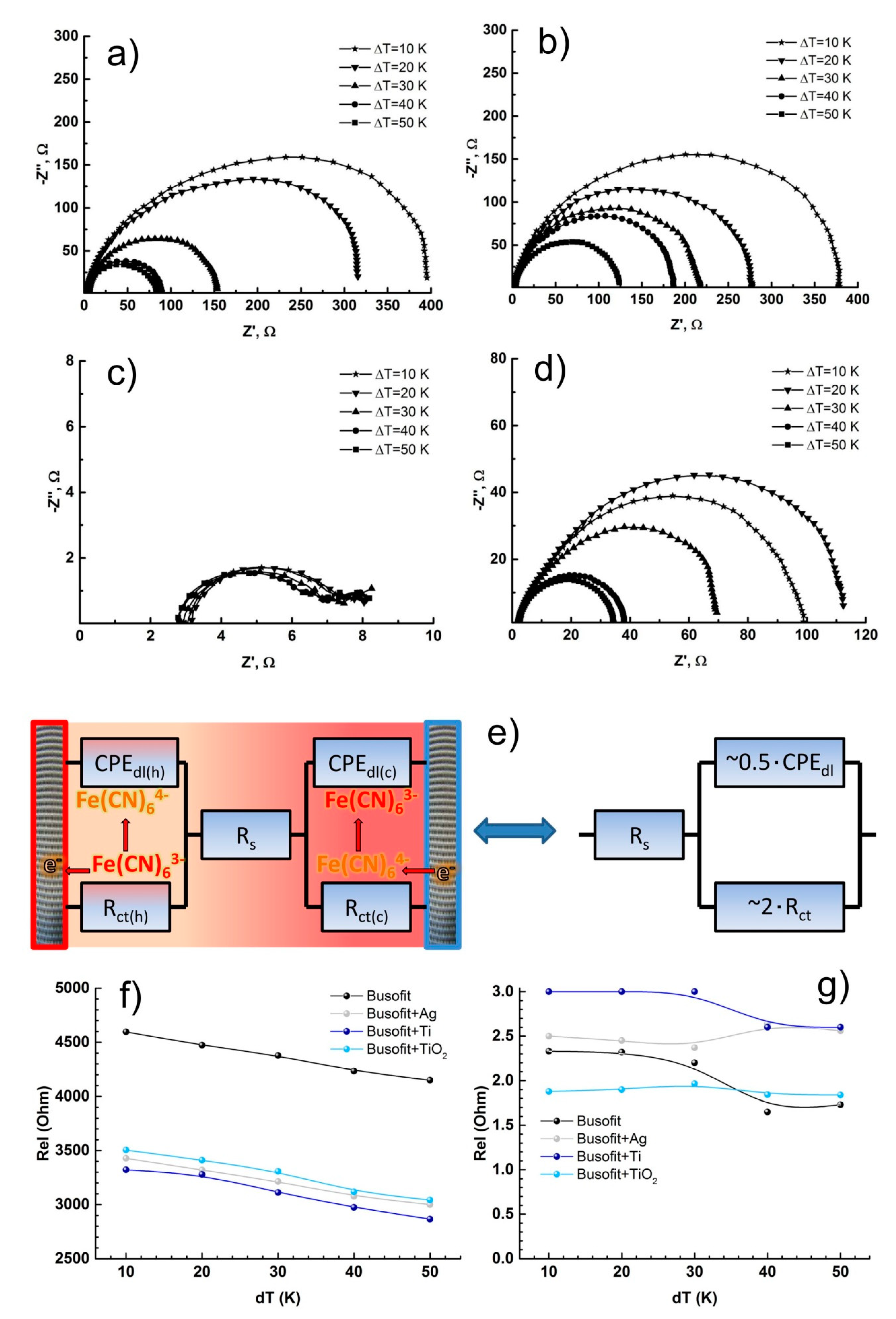
| Type of Electrodes | Rs (Ω) | Cdl (mkF) | Rct (Ω) |
|---|---|---|---|
| Busofit (Salt bridge) | 4150 | 6 | 1100 |
| Busofit (Coin cell) | 2 | 3 | 80 |
| Busofit+Ag (Salt bridge) | 3000 | 3 | 4090 |
| Busofit+Ag (Coin cell) | 2 | 3 | 120 |
| Busofit+Ti (Salt bridge) | 2870 | 3 | 201 |
| Busofit+Ti (Coin cell) | 2 | 10 | 5 |
| Busofit+TiO2 (Salt bridge) | 3040 | 6 | 430 |
| Busofit+TiO2 (Coin cell) | 2 | 3 | 30 |
Publisher’s Note: MDPI stays neutral with regard to jurisdictional claims in published maps and institutional affiliations. |
© 2021 by the authors. Licensee MDPI, Basel, Switzerland. This article is an open access article distributed under the terms and conditions of the Creative Commons Attribution (CC BY) license (http://creativecommons.org/licenses/by/4.0/).
Share and Cite
Artyukhov, D.; Kiselev, N.; Gorshkov, N.; Kovyneva, N.; Ganzha, O.; Vikulova, M.; Gorokhovsky, A.; Offor, P.; Boychenko, E.; Burmistrov, I. Harvesting Waste Thermal Energy Using a Surface-Modified Carbon Fiber-Based Thermo-Electrochemical Cell. Sustainability 2021, 13, 1377. https://doi.org/10.3390/su13031377
Artyukhov D, Kiselev N, Gorshkov N, Kovyneva N, Ganzha O, Vikulova M, Gorokhovsky A, Offor P, Boychenko E, Burmistrov I. Harvesting Waste Thermal Energy Using a Surface-Modified Carbon Fiber-Based Thermo-Electrochemical Cell. Sustainability. 2021; 13(3):1377. https://doi.org/10.3390/su13031377
Chicago/Turabian StyleArtyukhov, Denis, Nikolay Kiselev, Nikolay Gorshkov, Natalya Kovyneva, Olga Ganzha, Maria Vikulova, Alexander Gorokhovsky, Peter Offor, Elena Boychenko, and Igor Burmistrov. 2021. "Harvesting Waste Thermal Energy Using a Surface-Modified Carbon Fiber-Based Thermo-Electrochemical Cell" Sustainability 13, no. 3: 1377. https://doi.org/10.3390/su13031377
APA StyleArtyukhov, D., Kiselev, N., Gorshkov, N., Kovyneva, N., Ganzha, O., Vikulova, M., Gorokhovsky, A., Offor, P., Boychenko, E., & Burmistrov, I. (2021). Harvesting Waste Thermal Energy Using a Surface-Modified Carbon Fiber-Based Thermo-Electrochemical Cell. Sustainability, 13(3), 1377. https://doi.org/10.3390/su13031377