Article

Numerical and Experimental Investigation of a Thermoelectric-Based Radiant Ceiling Panel with Phase Change Material for Building Cooling Applications

by
Mohadeseh Seyednezhad
,
Hamidreza Najafi
* and
Benjamin Kubwimana
Department of Mechanical and Civil Engineering, Florida Institute of Technology, Melbourne, FL 32901, USA
*
Author to whom correspondence should be addressed.
Sustainability 2021, 13(21), 11936; https://doi.org/10.3390/su132111936
Submission received: 31 August 2021 / Revised: 24 October 2021 / Accepted: 26 October 2021 / Published: 28 October 2021

Abstract

:
The present paper investigates the performance of a thermoelectric (TE)-based radiant ceiling panel with an additional layer of phase change material (PCM) for building cooling application through numerical and experimental analyses. The design of the ceiling panel consisted of an aluminum sheet with TE modules installed on the back to maintain a relatively low ceiling temperature that provided cooling through radiation and convection. A three-dimensional model was developed in COMSOL Multiphysics, and the system’s performance in several different configurations was assessed. The effect of the number of TE modules, as well as incorporating different amounts of PCM under transient conditions, was investigated for two modes of operation: startup and shutdown. It was shown that for a 609.6 mm × 609.6 mm ceiling panel, the use of four TE modules reduced the average surface temperature down to the comfort range in less than 5 min while producing a relatively uniform temperature distribution across the ceiling panel. It was also shown that the addition of a 2 mm thick PCM layer to the back of the ceiling panel enhanced the system’s performance by elongating the time that it took for the ceiling panel’s temperature to exceed the comfort range when the system shut down, which in turn reduced the number of on/off cycling of the system. The numerical results demonstrated a good agreement with the experimental data. The results from this study can be used for the optimal design of a TE-based radiant ceiling cooling system as a promising technology for smart buildings.

1. Introduction

Over the last few decades, the population growth and increasing energy needs per capita have resulted in a major rise in energy demands worldwide. Higher energy demands have led to higher use of fossil fuels that are considered a threat for the environment. Energy consumption in the building sector is responsible for 40% of global energy consumption [1]. A significant portion of energy in buildings is consumed by heating, ventilation, and air conditioning (HVAC) systems. Furthermore, many heating/cooling systems rely on refrigerants, which are considered harmful to the environment. Researchers have been exploring alternative options that do not rely on refrigerants and offer good energy efficiency without sacrificing occupants’ comfort. A thermoelectric (TE) cooling module offers a solid-state technology that works based on the Peltier effect with no need for refrigerants, and has attracted increasing attention for its high controllability, environmentally friendly nature, and scalability. Additionally, TE modules are DC powered, lightweight, and portable, and do not require major mechanical parts [2,3,4].
TE modules can produce a temperature gradient when supplied with DC electricity (Peltier effect), or produce electricity when a temperature gradient is applied on their two sides (Seebeck effect). TE technology has various applications both through the Seebeck effect and Peltier effect, such as waste heat recovery [5,6], cooling systems for electronic devices [7,8,9], water desalination [10,11], and solar stills [12,13]. A comprehensive review of TE technology was carried out by Twaha et al. [14] and Sharma [15].
One of the novel applications of TE technology is in the cooling and heating systems in buildings, where it can be integrated or nonintegrated with the building envelope. The integrated system can be installed in windows [16,17] and walls [18,19,20,21]. Additionally, the nonintegrated system can be used as an individual unit, such as the ventilation system [22] or TE air coolers [23].
Several researchers have recently studied applications of thermoelectric cooling systems integrated into the ceiling [24]. The intention in applying a radiant cooling system rather than a conventional system is to provide thermal comfort for the occupants using radiant ceiling panels by increasing/decreasing the ceiling surface temperature [25]. These systems produce a cooling effect through radiation and free convection, where the former is responsible for at least half of the total heat exchange. The advantage of the radiant system over the conventional one has been discussed in many studies [26,27].
Lertsatitthanakorn et al. [28] investigated the performance of a TE-based radiant ceiling cooling panel. They used cold-water pipes as a heat sink on the hot side with constant water temperature. They showed that decreasing water temperature resulted in a better performance of the system. By evaluating the vertical temperature inside the room, they could show that the result was in the acceptable thermal comfort range. They could maintain the indoor air temperature at 27 °C and obtain a coefficient of performance (COP) value of 0.75. Since a water-cooled heat sink is an effective way to remove the heat from the hot side of TE modules, many researchers have used this method [29,30]. Cheng et al. [29] sandwiched a water channel plate between a solar panel and the hot side of a TE module. As expected, the temperature gradient between the hot and cold sides of the TE module decreased by increasing the water flow rate and reducing the inlet water temperature. Therefore, the performance of the radiant cooling system improved. Their result was in the acceptable range of thermal comfort.
Bhargava and Najafi [31] investigated the performance of a solar-driven thermoelectric cooling ceiling system and maintained the ceiling temperature in an acceptable comfort range for a simulated room. Seyednezhad and Najafi [32] conducted a feasibility study of using TE-based cooling systems for a full-scale office building in Florida through energy and economic analysis. The results showed that although the TE-based systems are significantly more expensive than their vapor-compression counterparts, they offer major advantages that allow them to become a competitive technology. Shen et al. [33] studied a TE-radiant cooling ceiling system and achieved a comparable COP value to that of the conventional HVAC system. He et al. [30] experimentally investigated both heating and cooling TE-radiant ceiling systems, and improved the COP to slightly higher than 0.45 in hot months. Liu et al. [34] developed a solar-driven TE-radiant panel for an experimental room. They evaluated the system’s performance under various operating conditions. Eventually, they achieved a COP value of 0.9 with an input voltage of 5 V in the cooling mode and a COP of 1.9 at 4 V in the heating mode.
The low COP value of most of the TE-radiant systems can cause a considerable increase in energy consumption, making it difficult to justify using TE-based technology for cooling (and heating) applications. The COP value increases with maintaining a relatively small temperature difference between the hot and cold side of the TE module. This needs to be facilitated using effective heat sink designs. Another challenge is the quick increase of the ceiling temperature when the system is turned off, which necessitates a longer operating time. A few studies recommended the integration of phase change material (PCM) as the heat sink to maintain a constant temperature [35,36]. It was shown that the PCM had the capability to store heat for an extended amount of time and, in turn, maintain a smaller temperature gradient across the module. In addition to the improved COP, PCM allows maintaining a constant temperature for an extended time after the system is turned off. Therefore, it can reduce the cooling system’s operating time and energy consumption.
Additionally, a few review studies have been conducted on the application of PCM heat storage in cooling systems in buildings [37,38]. Kang et al. [36] showed that PCM integrated with a TE-radiant ceiling system could maintain the room temperature at 19 °C for 4 h. Ansuini et al. [39] showed that a PCM integrated with a radiant floor system could save about 25% of water usage by the cooling systems and increase the indoor environment’s heat gain at a constant temperature.
The successful design and implementation of TE-based radiant ceiling systems integrated into ceilings require detailed studies of numerous aspects of the system, including but not limited to the design of the ceiling panels, energy efficiency, occupants’ comfort, and the economic aspects. As discussed earlier, studies that are focused on the detailed design of ceiling panels are scarce. The purpose of this study was to assess the design of a TE-based radiant ceiling panel, and particularly, to investigate the effect of the number of TE modules and the addition of various amounts of PCM on the performance of the system.
This paper focuses on the design and parametric study of a TE-based radiant ceiling panel with an integrated PCM for building cooling applications. For this purpose, a numerical model was developed in COMSOL to assess the system’s transient thermal performance. The goal was to maintain a uniform temperature distribution on the panel’s surface and sustain the desired temperature for an extended amount of time. A parametric study was performed to determine the optimal number and placement of the TE modules to achieve these goals. The effect of adding various amounts of PCM on the time that it took for the ceiling panel to reach the comfort level temperature during both startup and shutdown conditions also was assessed. Furthermore, the numerical model and the performance of the cooling panel were experimentally validated to ensure the accuracy of the COMSOL model. The results are discussed extensively, and can be used as a foundation for designing TE-based radiant ceiling panels and minimizing the cost for future experimental studies. This paper particularly provides insights regarding establishing a procedure to determine the optimal number of TE modules for a ceiling panel, and how the addition of PCM thermal storage can enhance the system’s performance in different modes of operation.

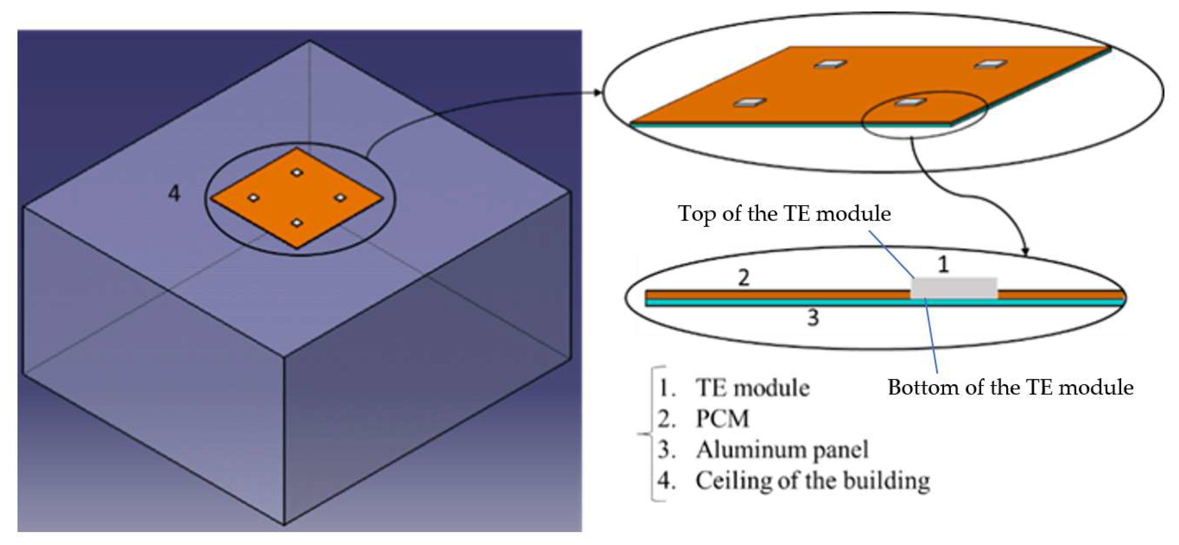
2. System Description

The system consisted of a ceiling panel composed of an aluminum sheet, TE modules, and a PCM layer. Figure 1 shows a schematic of the system.
The TE modules were mounted on the top side of the aluminum panel, and the PCM layer covered the remaining topside area. It was assumed that the top surface of the PCM layer and the entire panel’s surrounding surface area were perfectly insulated. The aluminum panel cooled down when the TE modules operated, and allowed heat exchange with the surrounding environment via radiation and natural convection. The PCM was integrated into the system to maintain a constant temperature at the desired level. Although the addition of PCM elongates the time it takes to bring down the ceiling panel’s temperature, it will help maintain it at the desired level when the system is off; therefore, it prevents the quick cycling of the system. Consequently, the optimal amount of PCM should be used to achieve the optimal balance.
An appropriate ceiling temperature for radiative cooling is 18–21 °C (291–294 K) [37]. To work efficiently, the system must reach a uniform surface temperature within the recommended range in a timely fashion and maintain the temperature for an extended time when it is not operating.
Two operating modes were considered to assess the system’s performance: in the first mode (mode-1: start-up), as the cooling system begins operating, the TE modules cool down immediately and cause a reduction of the temperature of the ceiling panel. The PCM (if used) begins solidifying (discharging) during this time while maintaining a relatively constant temperature. Over a small temperature interval, the transition process causes a gradual decrease in the ceiling temperature until all of the PCM is completely solidified. In practice, the system continues operating until the comfort conditions in space are met (temperature reaches 292 K). The system then shuts down, and as a result, the ceiling panel’s temperature gradually increases (mode-2). The ceiling gradually absorbs heat through radiation and convection, and the PCM begins melting (charging) accordingly. The ceiling panel temperature keeps increasing until it exceeds the comfort range (294 K). The system will then turn back on again to provide cooling for the occupants.

3. Numerical Analysis

The major design aspects in this study were the number of TE modules and the amount of PCM material added to the ceiling panel. A numerical analysis using COMSOL was performed to assess these design elements to achieve the system’s optimal configuration.

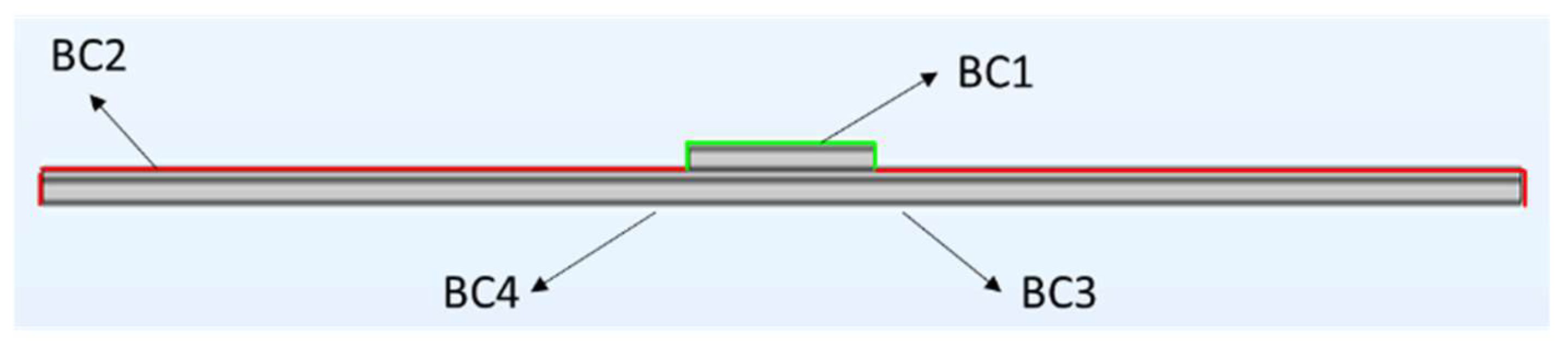
3.1. Assumptions: Initial and Boundary Conditions
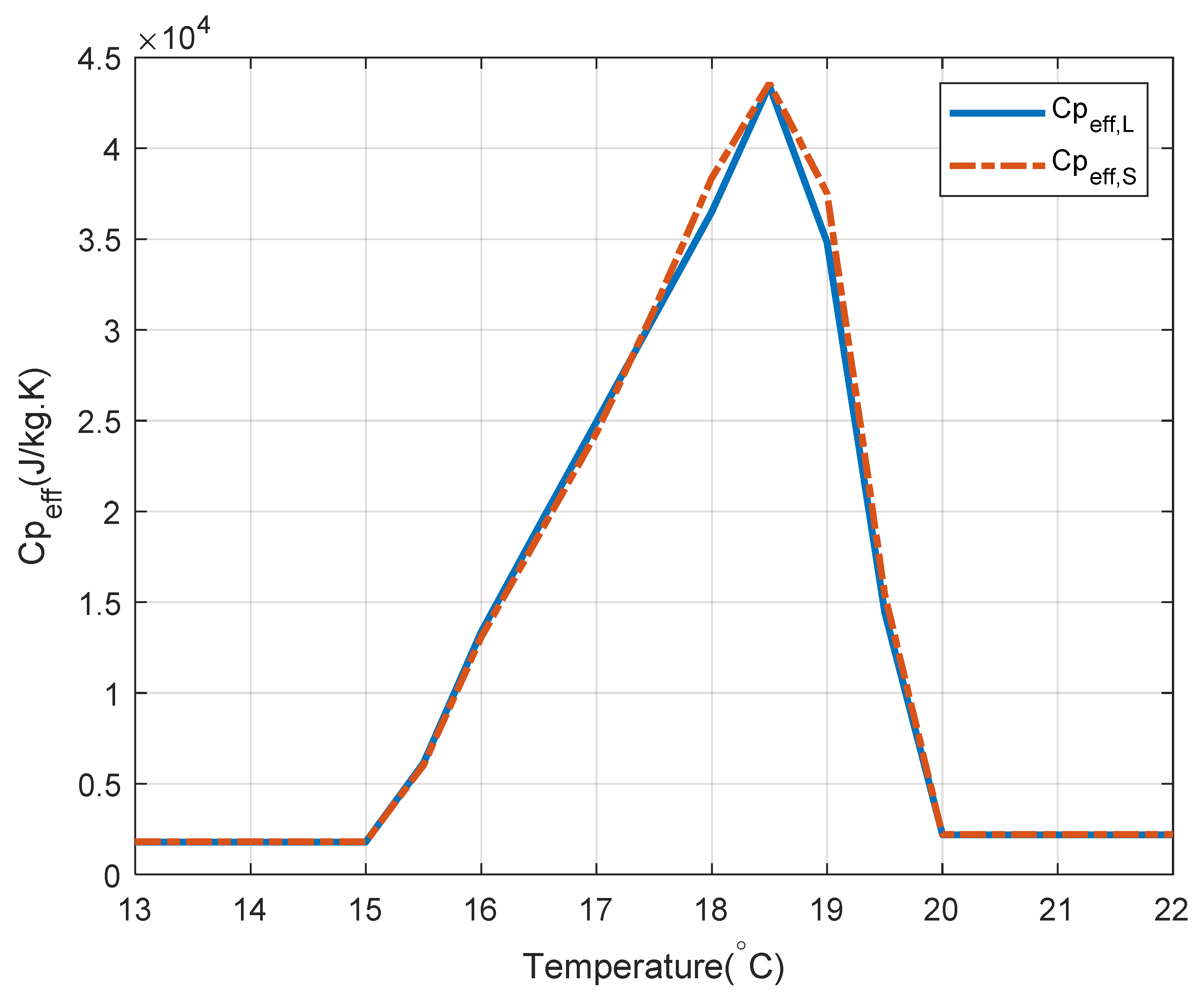
A transient simulation was conducted on the proposed system with a variable number of TE modules and different PCM thickness layers. The effect of these parameters on the performance of the system are discussed in the following sections. In addition, the characteristics of the TE modules are presented in Table 1. The features of the PCM layer and aluminum panel are presented in Table 2. The physics, and initial and boundary conditions, for the two transient modes of operations (startup and shutdown) are demonstrated in Table 3 and Table 4, respectively, and the prescribed boundary condition (BC) is demonstrated in Figure 2. For organic PCMs, the density ranged from 700 to 900 kg/m3, the thermal conductivity varied between 0.2 and 0.34 W/mK, and the melting temperature was between 21 °C and 57 °C [40]. It is also shown that the temperature range of 15 °C to nearly 30 °C is commonly used for paraffin and salt hydrates considered for the organic PCM [41]. The PCM characteristics shown in Table 2 are related to an organic-based commercial material available in pouches and bottles.
It was assumed that the entire system was initially at an ambient air temperature of 302.15 K for the startup mode. This was to simulate the cooling performance of the system when it began working on a warm day. When the system was operating to remove heat from the space, the TE modules were at a constant temperature of 12 °C, which in practice can be achieved by setting appropriate input electricity to the module and using the TE controller. The bottom side of the panel exchanged heats through radiation and convection with the surrounding environment. It should be noted that the convective heat transfer coefficient, h, was determined as 5 W/m2 K through the correlation for the Nusselt number for free convection at the bottom of a cold plate [43]. The energy balance equation for each component of the system is given by:
ρ C p T t + ρ C p u · T + · q c o n d = Q s t + Q r a d + Q v d
where qcond is the heat flux by conduction, ρ is the density, Cp is the specific heat at constant pressure, k is the thermal conductivity, and u is the velocity of translational motion of the natural air stream over and below the panel surface. In addition, Qst is the heat storage, and Qvd represents the viscous dissipation. The conduction heat flux can be found using Fourier’s law [43]:
q c o n d = k T
For the phase change material (PCM), the value of k, ρ and Cp are expressed as [44]:
k = θ k p h 1 + ( 1 θ ) k p h 2
ρ = θ ρ p h 1 + ( 1 θ ) ρ p h 2
C p = 1 ρ ( θ ρ p h 1 C p , p h 1 + ( 1 θ ) ρ p h 2 C p , p h 2 ) + L α T
where θ is a volume fraction of the melted PCM and varies between 0 and 1, based on the liquid–solid phase-transition process, L is the latent heat of fusion, and α is the mass fraction defined as:
α = 1 2 ( ( 1 θ ) ρ p h 2 θ ρ p h 1 θ ρ p h 1 + ( 1 θ ) ρ p h 2 )
BC1 describes a constant temperature (T0) on the TE modules operating at a certain electrical input. It should be noted that only the cold ceramic plate of the TE modules, which had a 1 mm thickness, was considered for simplification purposes. The temperature of the TE modules when the system was turned on is defined as:
T = T 0 = 285.15   K
As mentioned above, the entire top surface of the aluminum panel was not covered by TE modules, and the surrounding walls were perfectly insulated. The thermal insulation boundary condition (BC2) is described in Equation (8), in which n is the normal vector on the solid surface:
n · q i n s = 0
The convection heat transfer, qconv, occurs between the bottom side of the aluminum panel and the air inside the room (BC3), where h is the convective heat transfer coefficient, and Text is the temperature of the air in the vicinity of the back of the aluminum panel.
n · q = q c o n v
q c o n v = h ( T e x t T )
BC4 describes the prescribed radiosity with the negative direction, where the graybody radiation expression is given as [43]:
J = ϵ e b l ( T ) + ρ d G
where ε is the emissivity and ebl (T) is the black body emissive power, which is a function of the reflective index (π) and the fourth power of the surface temperature (see Equation (12)). It should be noted that the absorptivity and emissivity were equal. In Equation (11), G is the solar irradiance and ρd represents the diffusive reflectivity.
e b l ( T ) = π 2 σ T 4
It was noteworthy that the surface-to-surface radiation interface assumed that the surface emissivity and properties of the opaque surface were constant per spectral band. The initial and boundary conditions in the mode-2 analysis were different from those in mode-1, as shown in Table 4.

3.2. COMSOL Model

A 3D model was developed in COMSOL Multiphysics 5.5a. The effective specific heat capacity (cp,eff) method was used for the PCM to model the heat capacity at constant pressure [45]. The validity of this model will be later explored through the experimental study in Section 5. Figure 3 shows the modified heat capacity that was generated by the piecewise cubic interpolation function in COMSOL. The calculation was based on the melting temperature intervals and the latent heat magnitude [35,46,47]. This step was essential due to difficulty in the numerical analysis to simulate the phase change at an exact melting temperature [48]. Equations (13) and (15) summarize the functions that were used for calculating the effective specific heat for the charging and discharging processes. It was indicated by Ye et al. [49] that the result of the effective heat capacity method and the enthalpy method agreed with each other as long as the properties of PCM were properly determined by a differential scanning calorimetry (DSC) test.
C p , m e l t i n g C p , s   T < 15   ° C C p , m a x + C p , m a x C p , s 18.8 15 ( T 15 ) 15   ° C T < 18.8   ° C C p , m a x + C p , l C p , m a x 20 18.8 ( T 15 ) 18.8   ° C T 20   ° C C p , l T > 20   ° C
C p , s o l i d i f y i n g C p , s   T < 15   ° C C p , m a x + C p , m a x C p , s 18.8 15 ( T 15 ) 15   ° C T < 18.8   ° C C p , m a x + C p , l C p , m a x 20 18.8 ( T 15 ) 18.8   ° C T 20   ° C C p , l T > 20   ° C
where:
C p ,   m a x = Q Δ T C p , s + C p , l 2
The finite element method was employed to solve all governing PDEs in transient mode with physics-controlled tolerance. A free tetrahedral and triangular type mesh was used with the whole range of 7817–40,595 elements. The mesh was made finer for TE modules, and coarser for the aluminum panel and PCM layer. This was to avoid excessive calculation time. The element’s quality was measured by the skewness method. A grid independence check was conducted to guarantee that the numerical solution did not vary with the number of grids.

4. Results and Discussion

A time-dependent parametric study was performed to determine the required number of TE modules and the optimum thickness of the PCM layer that resulted in a uniform temperature through the ceiling panel, and could reach and maintain the comfort temperature in a reasonable amount of time.

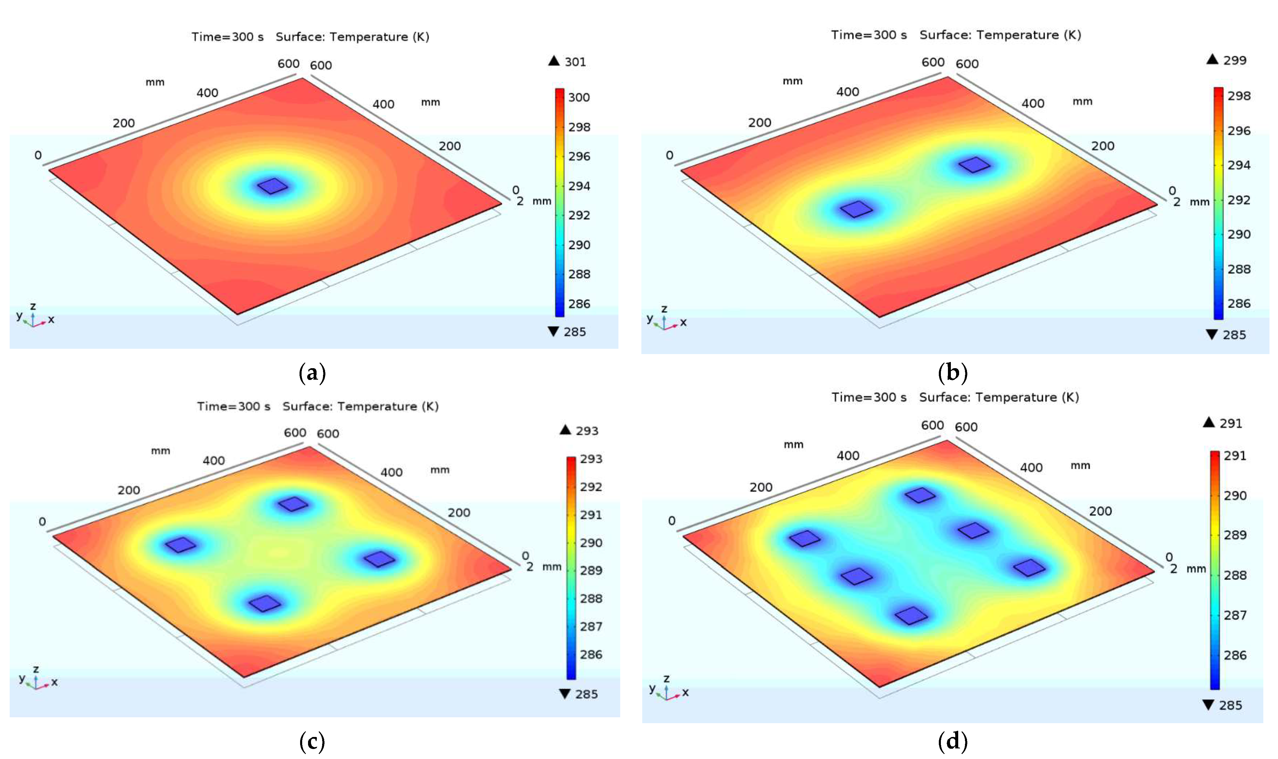
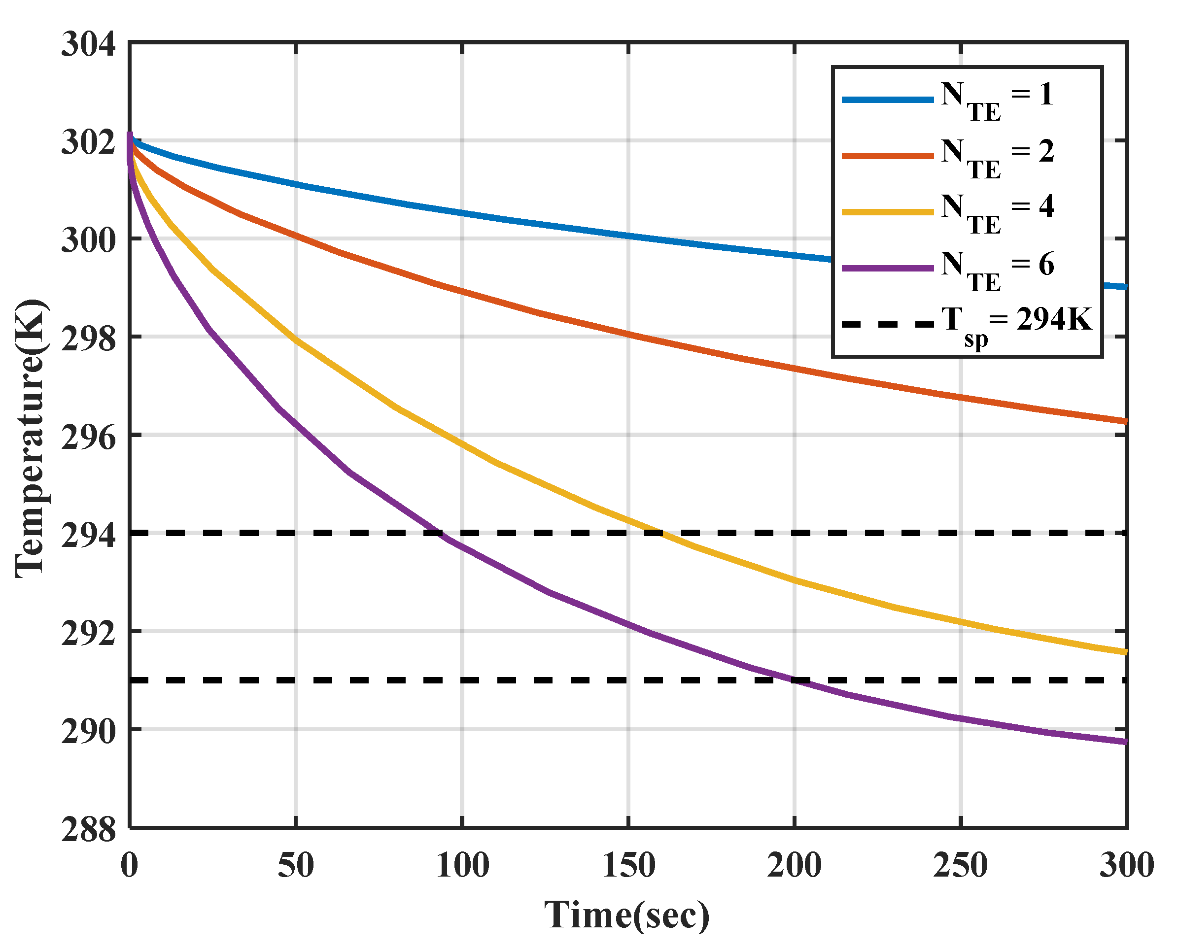
4.1. Temperature Variation: The Effect of Number of TE Modules

Figure 4 shows the variation in the number of TE modules installed on the aluminum panel surface with a 2 mm thickness. It can be seen that an increase in the number of TE modules decreased the maximum temperature on the ceiling panel and allowed a more uniform temperature distribution. Using one or two TE modules, the temperature distribution across the ceiling panel dramatically varied. The central parts in the vicinity of the TE modules were much cooler than the other areas. With the use of four or six TE modules, a more uniform temperature distribution was observed throughout the ceiling panel’s surface, except for the corners. This will allow a more effective and uniform cooling effect.
Figure 5 demonstrates the variation of the average temperature of the bottom side of the aluminum panel versus time. The intent was to determine the least number of TE modules that met the requirement of staying within the comfort temperature in an acceptable amount of time. For this purpose, a target time of approximately 3–5 min was considered. The minimum number of TE modules that could bring the ceiling temperature well within the comfort range (291–294 K) during this time was determined.
As shown in Figure 5, when one or two TE modules were in use, it took much longer than 3 min for the panel to cool down and reach the maximum comfort temperature of 294 K. The model with six TE modules significantly surpassed the desired time for reaching the set point temperature. Figure 5 shows that the panel with four TE modules led to the most desirable outcome. It could reach 294 K within 158 s (2.38 min) and further down to 291 K in 330 s (5.25 min) while achieving a uniform temperature distribution (Figure 4).

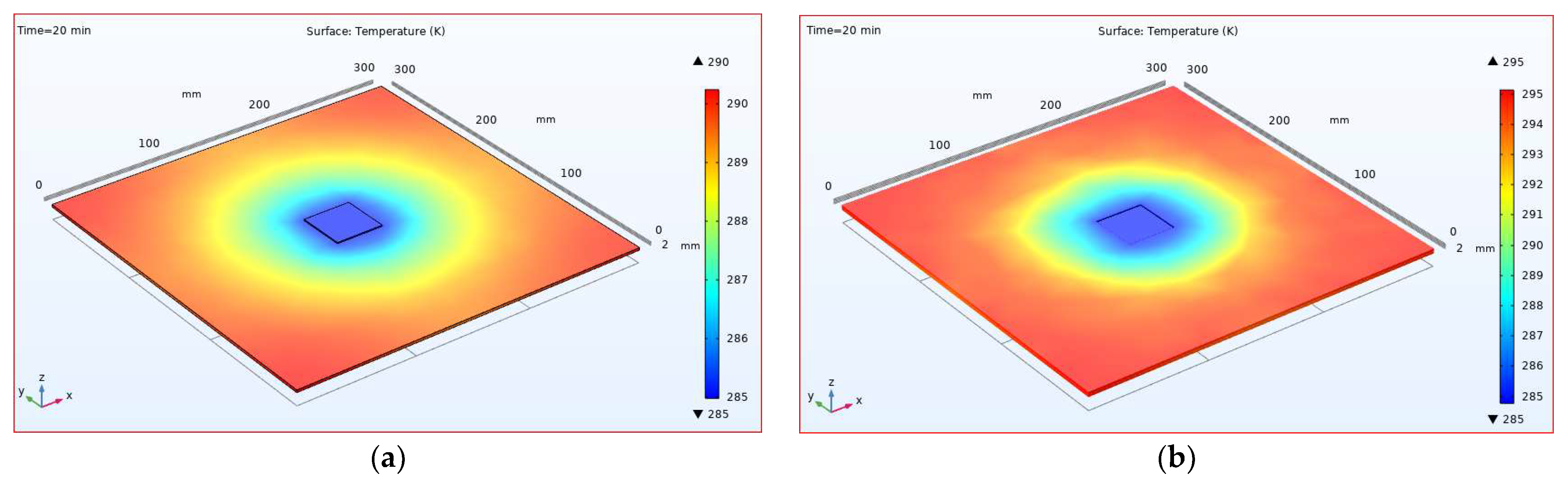
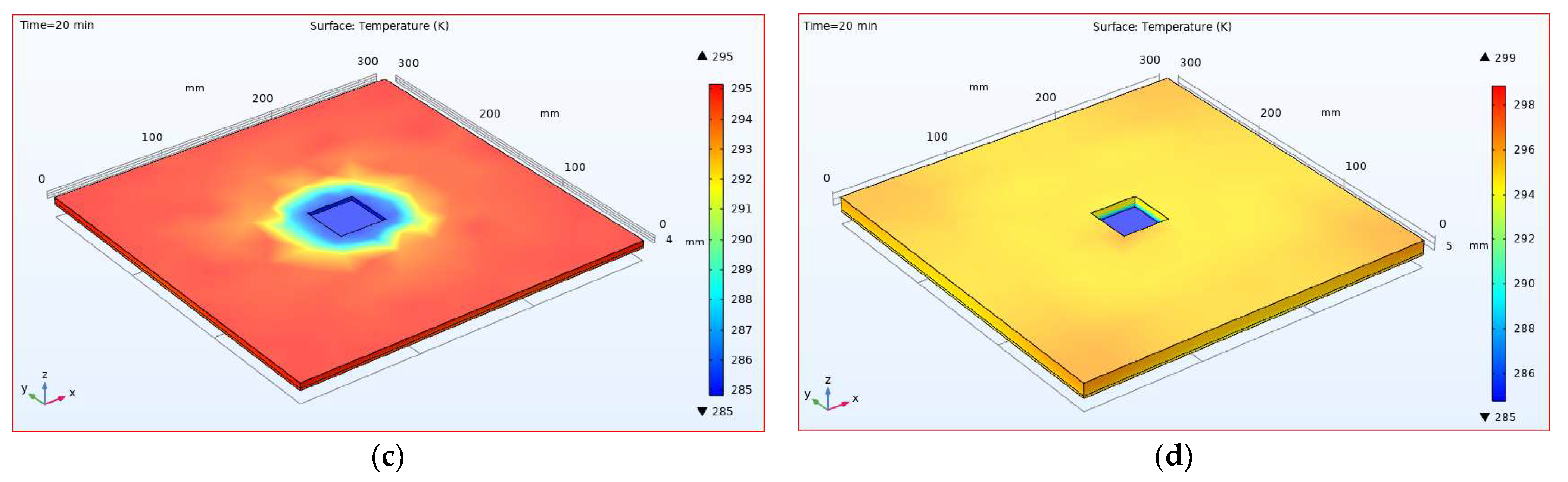
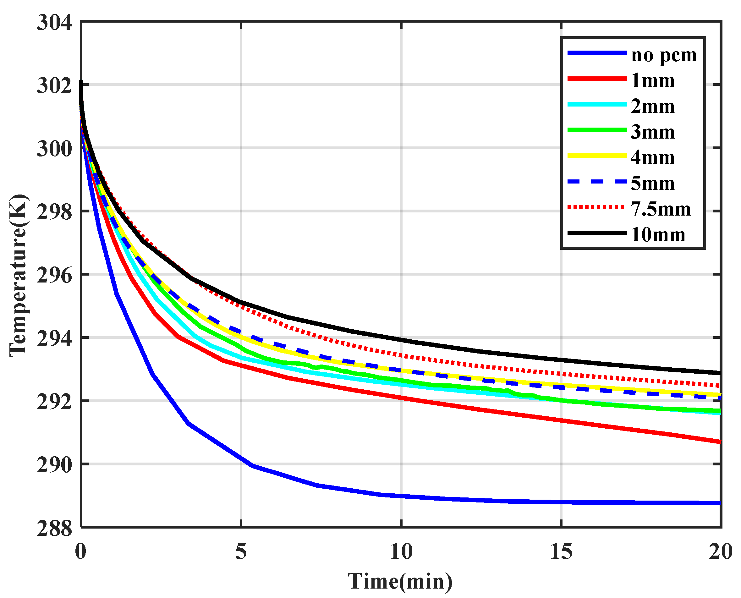
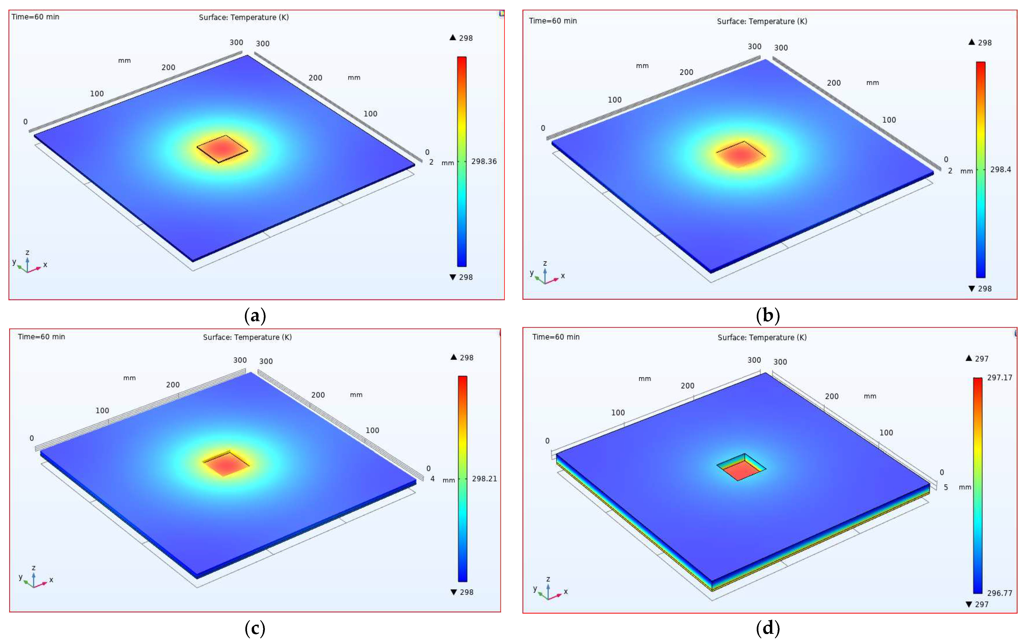
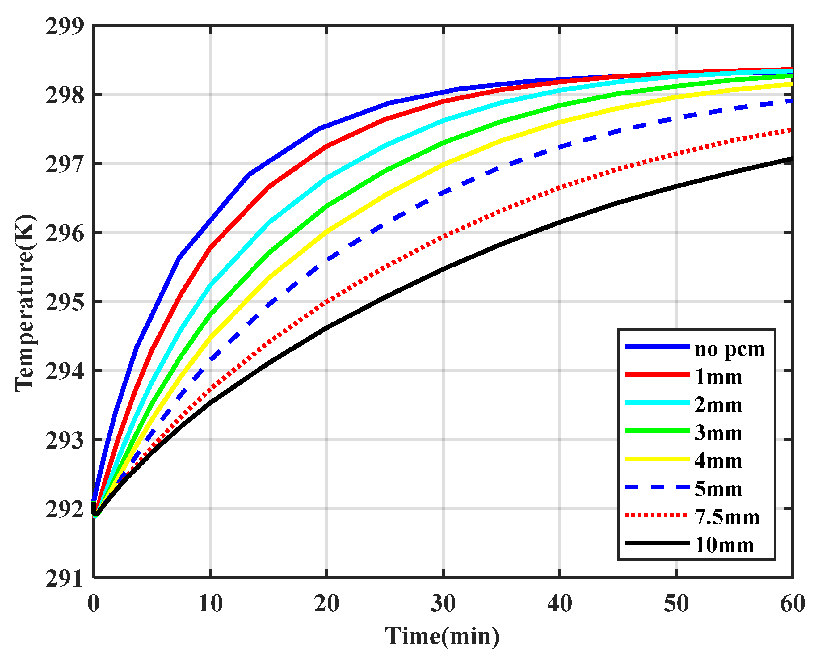
4.2. Temperature Variation: The Effect of PCM Addition

The effect of increasing the PCM layer thickness was assessed via simulations, the results of which are presented in this section. In order to reduce the calculation time, only a quarter of the panel was modeled, given the axisymmetric condition of the geometry. Multiple simulations were performed for various thicknesses of PCM.
Figure 6 shows the results of the mode-1 analysis for the cooling panel with various PCM thicknesses. All layers are initially at an ambient temperature of 302.15 K. The phase change began at 290 K and ended at 283 K, with a solidifying (discharging) temperature peak of 289 K. After an extended amount of time (20 min/~1200 s), the temperature distributions were plotted as shown in Figure 6 for cases with no PCM and with PCM layers with thicknesses of 2 mm, 4 mm, and 10 mm. It can be seen that with a larger amount of PCM (thicker layer), the temperature distribution across the panel became more uniform. In addition, as the thickness of the PCM layer increased, the panel’s maximum temperature increased. This was due to the storage characteristics of the PCM layer, which slowed the cooling process.
Figure 7 provides a comparison between the average temperatures of the bottom side of the aluminum panel for various cases (with no PCM layer and with different PCM thicknesses). The simulations were performed for 20 min. As seen in Figure 7, the addition of the PCM layer and the increase in its thickness resulted in a significant decrease in the temperature profile slope. In other words, adding PCM (more thermal storage) increased the amount of time that it took to reduce the temperature using TE modules. The model’s temperature with no PCM reached 289 K after 9 min (~540 s). This was well below the desired ceiling temperature (291–294 K). This configuration reached a temperature of 294 K within 2 min. It should be noted that excessive reduction in ceiling temperature could lead to local discomfort due to draft formation on the aluminum surface, although the lower surface temperature would lead to a greater cooling capacity of the system. In the absence of PCM, it took 120 s and 330 s to reach 294 K and 291 K, respectively.
Due to the latent heat storage capability, the models with a PCM layer required a longer time to reach the desired temperature. The average surface temperature of the models with a 2 mm PCM layer dropped from 302 K to 294 K and 291 K in 3.5 min and almost 25 min, respectively. Based on the findings from the mode-1 analysis, we concluded that when the PCM layer was 2 mm thick, the system offered an enhanced performance; the panel reached a relatively uniform surface temperature (Figure 6b). The average surface temperature of the panel reached 294 K and 291 K in 3.5 min and 25 min, respectively (Figure 7).
Similar findings were reported by Lertsatitthanakorn et al. [50], who studied the ceiling temperature under various inputs of electricity. For the ceiling of a 4.5 m3 chamber with 36 TE modules, when Tamb = 30 °C, the ceiling temperature reached about 288 K in less than 10 min, which was expected for a cooling system without PCM. The addition of a PCM layer made the temperature reduction time slightly longer. However, it facilitated reaching a more uniform temperature and maintained the temperature for an extended time when the system shut down (mode-2 operation).
Figure 8 shows the simulation result of the mode-2 operation (shutdown) analysis. The simulation for mode-2 was performed for 60 min. As seen, the larger amount of PCM slowed the temperature increase when the TE modules were not in operation.
Figure 9 demonstrates that the model without PCM experienced a temperature increase at a faster rate. A 2 mm thick PCM layer maintained the average bottom surface temperature below 294 K for nearly 5 min versus the case with no PCM, which could only maintain the temperature within the comfort range for about 2 min.

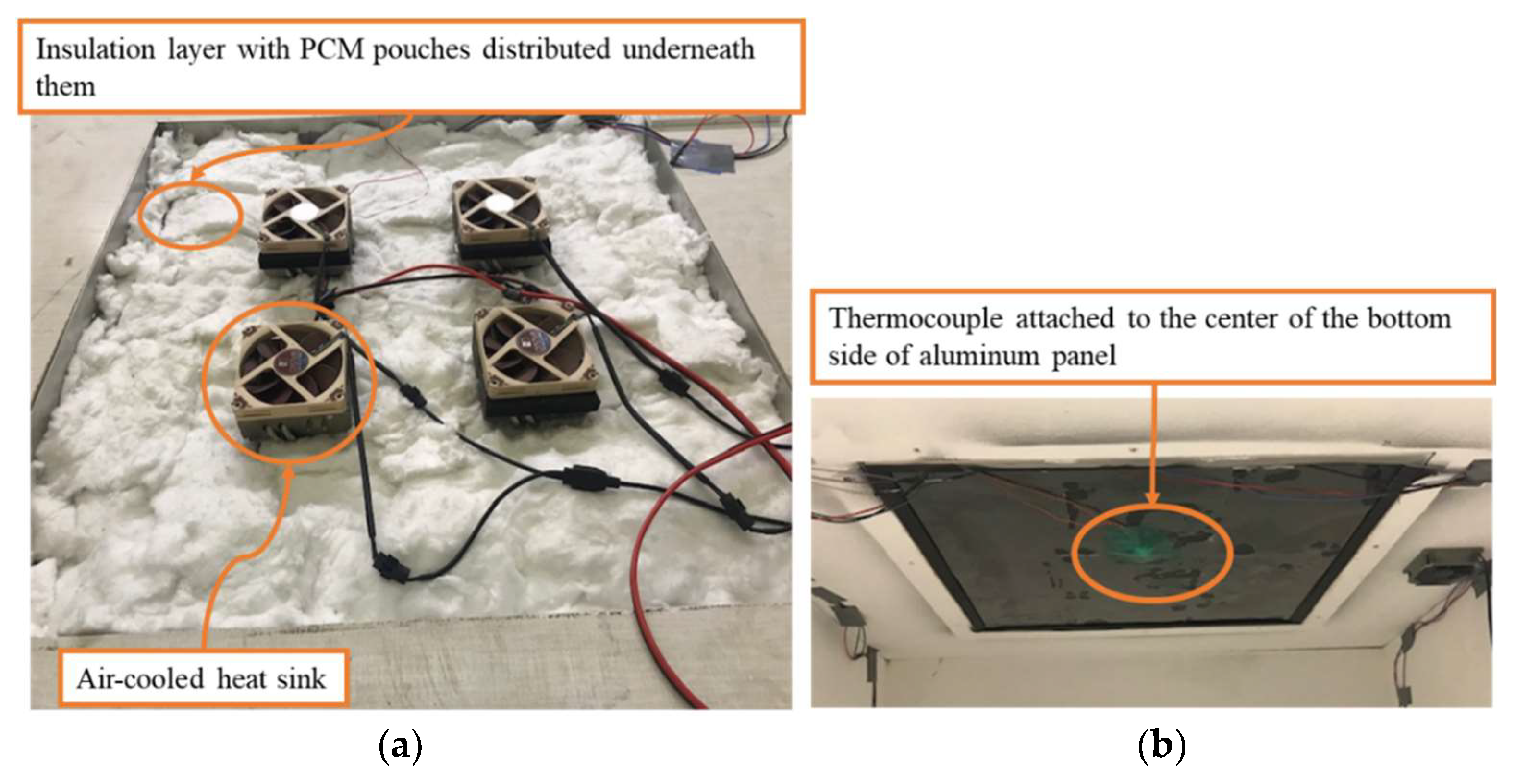
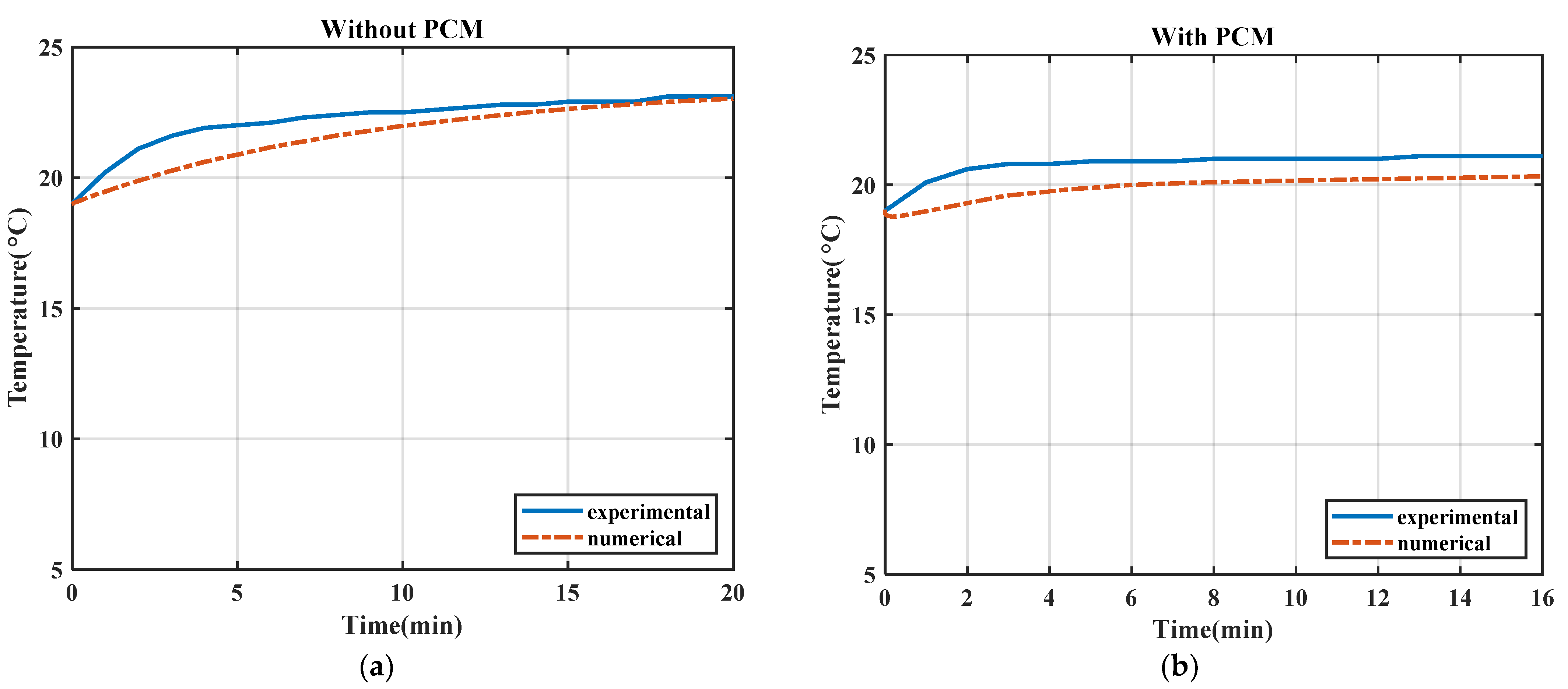
5. Experiment and Model Validation

A TE-based radiant ceiling panel was constructed, and a series of experiments was performed to validate the results from the numerical simulation, and mainly the accuracy of the PCM characteristics that were defined in COMSOL, as discussed in Section 3.2. As shown in Figure 10, four TE modules were installed on the 2 mm thick, 609.6 mm × 609.6 mm square-shaped aluminum panel that was integrated into the ceiling of a small chamber. The number of the TE modules and their placement on the proposed cooling panel were determined based on the numerical analysis. An air-cooled heat sink was attached on the top side of each TE module in order to dissipate the heat removed by the TE modules properly. The PCM pouches were placed on top of the aluminum panel and were covered with a layer of insulation. Overall, six pouches of a 50.8 mm × 152.4 mm size and six pouches of a 127 mm × 152.4 mm size were used, all of which contained a mixture of organic materials that had properties compatible with the required temperature range for thermal comfort.
The experiments were conducted in a controlled environment. The indoor humidity was maintained at approximately 50%, and the room temperature was about 22 °C. T-type thermocouples (±1 °C) were used to measure the temperature variation on the back surface of the aluminum panel and the hot surface of the TE modules. The temperatures measured by the thermocouples were recorded using a data logger with a frequency of one second.
The experiment began with a solid PCM layer (that was cooled down in a refrigerator) to explore the mode-2 operation. Before placing the PCM pouches on the top surface of the panel, the TE modules were activated using a power supply, and the temperature of the center of the panel reached 18 °C (291.15 K), which was within the acceptable comfort temperature range (291–294 K).
Once the system reached a steady-state condition, the solid-state PCM pouches at 18 °C (291.15 K) were evenly distributed on the top surface of the panel with an overall thickness of 2 mm, and were covered by a reasonably thick layer of insulation to avoid exchange of thermal energy with the surrounding environment. Then, the TE modules were deactivated (shut down), and the transient temperatures of the aluminum panel were recorded until the PCM was fully liquefied (melted).
Two experimental cases were carried out to investigate the effect of the addition of PCM to the system for the case without a PCM layer and the case with a 2 mm thick PCM layer. A COMSOL simulation was performed according to the model that was previously described. For the numerical model, convection and surface-to-surface radiation heat transfer were considered for both the TE modules and the bottom surface of the aluminum panel. The ambient temperature of the controlled room was maintained at 296.15 K with 50% humidity. The convection heat transfer coefficient for the bottom of the aluminum panel was found to be 4 W/m2 K, and for the top side of the TE module, was found to be 20 W/m2 K. As shown in Figure 11, the transient temperature at the center of the bottom side of the aluminum panel was compared with the estimated temperature in the computational model.
In the numerical simulation, the initial temperature of each component and the boundary conditions were set to be identical to the values and conditions in the experiment. As shown in Figure 11b, the temperature of the aluminum increased for nearly 3 and 4 min, and reached around 19.82 °C and 20.8 °C, for the numerical and the experimental cases, respectively. Then, the surface temperature of the aluminum remained constant for an extended period of time, after which the phase change occurred and discharged the latent heat. A good agreement between the numerical and experimental data was observed (Figure 11). The normalized root-mean-square method (N-RMSE) was used to compare the experimental and computational data. In the absence of a PCM layer, the N-RMSE value was found to be 0.09, and in the presence of the 2 mm thick PCM layer, the N-RMSE was found to be 0.55.

6. Conclusions

The design and performance of a TE-based radiant ceiling panel for building cooling applications was investigated. A detailed model of the system was developed in COMSOL Multiphysics, and the numerical analysis was conducted under transient conditions for two modes of operation (startup and shutdown). The system consisted of TE modules attached to the top surface of the aluminum panel. A parametric study was performed to assess the effect of the number of TE modules and the addition of PCM to the ceiling panel on the performance of the system. It was shown that for a 609.6 mm × 609.6 mm ceiling panel, using four TE modules resulted in decreasing the average surface temperature down to the comfort range (291–294 K) in less than 5 min; as such, it could facilitate a relatively uniform temperature distribution throughout the surface of the ceiling panel. It was also demonstrated that the addition of a 2 mm thick PCM layer to the back of the ceiling panel improved the performance of the system by extending the amount of time (by 200 s) that it took for the ceiling panel temperature to surpass the comfort range after the system shut down. This improvement reduced the number of on/off cyclings of the system, thereby improving the system’s operation.
Additionally, to verify the numerical model, two experiments were performed to monitor the transient thermal behavior of the TE-based radiant ceiling panel with and without the addition of the PCM layer. It was shown that the results of the numerical model were in good agreement with the experimental data in both cases. The results from this study can be used in the design of an optimal TE-based radiant ceiling system.

Author Contributions

Formal analysis, writing—original draft preparation, M.S.; Conceptualization, methodology, investigation, writing—review and editing, H.N.; Experiment, validation, B.K. All authors have read and agreed to the published version of the manuscript.

Funding

The validation experiment in this research was performed through the apparatus that was built using the Undergraduate Equipment Grant from American Society of Heating, Refrigerating and Air Conditioning Engineers (ASHRAE).

Conflicts of Interest

The authors declare no conflict of interest.

References

  1. Betharte, O.; Najafi, H.; Nguyen, T. Towards Net-Zero Energy Buildings: A Case Study in Humid Subtropical Climate. In Proceedings of the ASME International Mechanical Engineering Congress and Exposition (IMECE), Pittsburgh, PA, USA, 9–15 November 2018; Volume 6A-144113. [Google Scholar] [CrossRef]
  2. Cai, Y.; Zhang, D.-D.; Liu, D.; Zhao, F.-Y.; Wang, H.-Q. Air source thermoelectric heat pump for simultaneous cold air delivery and hot water supply: Full modeling and performance evaluation. Renew. Energy 2019, 130, 968–981. [Google Scholar] [CrossRef]
  3. Zhao, D.; Tan, G. A review of thermoelectric cooling: Materials, modeling and applications. Appl. Therm. Eng. 2014, 66, 15–24. [Google Scholar] [CrossRef]
  4. Najafi, H. Evaluation of Alternative Cooling Techniques for Photovoltaic Panels. Master’s Thesis, University of Alabama, Tuscaloosa, AL, USA, 2012. [Google Scholar]
  5. Kim, T.Y.; Negash, A.A.; Cho, G. Waste heat recovery of a diesel engine using a thermoelectric generator equipped with customized thermoelectric modules. Energy Convers. Manag. 2016, 124, 280–286. [Google Scholar] [CrossRef]
  6. Crane, D.T.; Jackson, G. Optimization of cross flow heat exchangers for thermoelectric waste heat recovery. Energy Convers. Manag. 2004, 45, 1565–1582. [Google Scholar] [CrossRef]
  7. Cai, Y.; Wang, Y.; Liu, D.; Zhao, F.-Y. Thermoelectric cooling technology applied in the field of electronic devices: Updated review on the parametric investigations and model developments. Appl. Therm. Eng. 2019, 148, 238–255. [Google Scholar] [CrossRef]
  8. Siddique, A.R.M.; Muresan, H.; Majid, S.H.; Mahmud, S. An adjustable closed-loop liquid-based thermoelectric electronic cooling system for variable load thermal management. Therm. Sci. Eng. Prog. 2019, 10, 245–252. [Google Scholar] [CrossRef]
  9. Simons, R.E.; Chu, R.C. Application of thermoelectric cooling to electronic equipment: A review and analysis. In Proceedings of the Sixteenth Annual IEEE Semiconductor Thermal Measurement and Management Symposium, San Jose, CA, USA, 23 March 2000; pp. 1–9. [Google Scholar] [CrossRef]
  10. Tan, Y.Z.; Han, L.; Chew, N.G.P.; Chow, W.H.; Wang, R.; Chew, J.W. Membrane distillation hybridized with a thermoelectric heat pump for energy-efficient water treatment and space cooling. Appl. Energy 2018, 231, 1079–1088. [Google Scholar] [CrossRef]
  11. Riahi, A.; Zakaria, N.; Noh, N.; Amin, M.; Jusoh, A.; Ideris, M.; Muhammad, M.; Ramli, M.; Zainol, M.; Shaharuddin, S.; et al. Performance Investigation of 18 Thermoelectric Cooler (TEC) Units to Supply Continuous Daily Fresh Water from Malaysia’s Atmosphere. Sustainability 2021, 13, 1399. [Google Scholar] [CrossRef]
  12. Dehghan, A.A.; Afshari, A.; Rahbar, N. Thermal modeling and exergetic analysis of a thermoelectric assisted solar still. Sol. Energy 2015, 115, 277–288. [Google Scholar] [CrossRef]
  13. Esfahani, J.A.; Rahbar, N.; Lavvaf, M. Utilization of thermoelectric cooling in a portable active solar still—An experimental study on winter days. Desalination 2011, 269, 198–205. [Google Scholar] [CrossRef]
  14. Twaha, S.; Zhu, J.; Yan, Y.; Li, B. A comprehensive review of thermoelectric technology: Materials, applications, modelling and performance improvement. Renew. Sustain. Energy Rev. 2016, 65, 698–726. [Google Scholar] [CrossRef]
  15. Sharma, S.; Dwivedi, V.K.; Pandit, S.N. A Review of Thermoelectric Devices for Cooling Applications. Int. J. Green Energy 2014, 11, 899–909. [Google Scholar] [CrossRef]
  16. Xu, X.; Van Dessel, S. Evaluation of an Active Building Envelope window-system. Build. Environ. 2008, 43, 1785–1791. [Google Scholar] [CrossRef]
  17. Xu, X.; Van Dessel, S. Evaluation of a prototype active building envelope window-system. Energy Build. 2008, 40, 168–174. [Google Scholar] [CrossRef]
  18. Liu, Z.; Zhang, L.; Gong, G.; Han, T. Experimental evaluation of an active solar thermoelectric radiant wall system. Energy Convers. Manag. 2015, 94, 253–260. [Google Scholar] [CrossRef]
  19. Irshad, K.; Habib, K.; Basrawi, F.; Saha, B. Study of a thermoelectric air duct system assisted by photovoltaic wall for space cooling in tropical climate. Energy 2017, 119, 504–522. [Google Scholar] [CrossRef]
  20. Luo, Y.; Zhang, L.; Liu, Z.; Yu, J.; Xu, X.; Su, X. Towards net zero energy building: The application potential and adaptability of photovoltaic-thermoelectric-battery wall system. Appl. Energy 2020, 258, 114066. [Google Scholar] [CrossRef]
  21. Liu, Z.; Zhang, L.; Gong, G.; Luo, Y.; Meng, F. Evaluation of a prototype active solar thermoelectric radiant wall system in winter conditions. Appl. Therm. Eng. 2015, 89, 36–43. [Google Scholar] [CrossRef]
  22. Zuazua-Ros, A.; Martín-Gómez, C.; Ibañez-Puy, E.; Vidaurre-Arbizu, M.; Gelbstein, Y. Investigation of the thermoelectric potential for heating, cooling and ventilation in buildings: Characterization options and applications. Renew. Energy 2019, 131, 229–239. [Google Scholar] [CrossRef]
  23. Irshad, K. Performance Improvement of Thermoelectric Air Cooler System by Using Variable-Pulse Current for Building Applications. Sustainability 2021, 13, 9682. [Google Scholar] [CrossRef]
  24. Lim, H.; Kang, Y.-K.; Jeong, J.-W. Development of empirical models to predict cooling performance of a thermoelectric radiant panel. Energy Build. 2019, 202, 109387. [Google Scholar] [CrossRef]
  25. Catalina, T.; Virgone, J.; Kuznik, F. Evaluation of thermal comfort using combined CFD and experimentation study in a test room equipped with a cooling ceiling. Build. Environ. 2009, 44, 1740–1750. [Google Scholar] [CrossRef]
  26. Li, R.; Yoshidomi, T.; Ooka, R.; Olesen, B.W. Field evaluation of performance of radiant heating/cooling ceiling panel system. Energy Build. 2015, 86, 58–65. [Google Scholar] [CrossRef]
  27. Luo, Y.; Zhang, L.; Liu, Z.; Wang, Y.; Meng, F.; Xie, L. Modeling of the surface temperature field of a thermoelectric radiant ceiling panel system. Appl. Energy 2016, 162, 675–686. [Google Scholar] [CrossRef]
  28. Han, T.; Gong, G.; Liu, Z.; Zhang, L. Optimum design and experimental study of a thermoelectric ventilator. Appl. Therm. Eng. 2014, 67, 529–539. [Google Scholar] [CrossRef]
  29. Cheng, T.-C.; Cheng, C.-H.; Huang, Z.-Z.; Liao, G.-C. Development of an energy-saving module via combination of solar cells and thermoelectric coolers for green building applications. Energy 2011, 36, 133–140. [Google Scholar] [CrossRef]
  30. He, W.; Zhou, J.; Hou, J.; Chen, C.; Ji, J. Theoretical and experimental investigation on a thermoelectric cooling and heating system driven by solar. Appl. Energy 2013, 107, 89–97. [Google Scholar] [CrossRef]
  31. Bhargava, A.; Najafi, H. Photovoltaic-Thermoelectric Systems for Building Cooling Applications: A Preliminary Study. In Proceedings of the ASME 2016 International Mechanical Engineering Congress and Exposition, Phoenix, AZ, USA, 11–17 November 2016; Volume 6B. [Google Scholar] [CrossRef]
  32. Seyednezhad, M.; Najafi, H. Solar-Powered Thermoelectric-Based Cooling and Heating System for Building Applications: A Parametric Study. Energies 2021, 14, 5573. [Google Scholar] [CrossRef]
  33. Shen, L.; Xiao, F.; Chen, H.; Wang, S. Investigation of a novel thermoelectric radiant air-conditioning system. Energy Build. 2013, 59, 123–132. [Google Scholar] [CrossRef]
  34. Liu, Z.; Zhang, L.; Gong, G. Experimental evaluation of a solar thermoelectric cooled ceiling combined with displacement ventilation system. Energy Convers. Manag. 2014, 87, 559–565. [Google Scholar] [CrossRef]
  35. Lim, H.; Cho, H.-J.; Cheon, S.-Y.; Lee, S.-J.; Jeong, J.-W. A numerical model and validation of phase change material integrated thermoelectric radiant cooling panel. In Proceedings of the CLIMA 2019 Congress, Bucharest, Romania, 26–29 May 2019; Volume 111, p. 01001. [Google Scholar] [CrossRef] [Green Version]
  36. Kang, Y.-K.; Kim, B.-J.; Yoon, S.-Y.; Jeong, J.-W. Experimental evaluation of phase change material in radiant cooling panels integrated with thermoelectric modules. In Proceedings of the CLIMA 2019 Congress, Bucharest, Romania, 26–29 May 2019; Volume 111, p. 01002. [Google Scholar] [CrossRef]
  37. Osterman, E.; Tyagi, V.; Butala, V.; Rahim, N.; Stritih, U. Review of PCM based cooling technologies for buildings. Energy Build. 2012, 49, 37–49. [Google Scholar] [CrossRef]
  38. Souayfane, F.; Fardoun, F.; Biwole, P.-H. Phase change materials (PCM) for cooling applications in buildings: A review. Energy Build. 2016, 129, 396–431. [Google Scholar] [CrossRef]
  39. Ansuini, R.; Larghetti, R.; Giretti, A.; Lemma, M. Radiant floors integrated with PCM for indoor temperature control. Energy Build. 2011, 43, 3019–3026. [Google Scholar] [CrossRef]
  40. Singh, D.; Gautam, A.K.; Chaudhary, R. Application of phase change material in building integrated photovoltaics: A review. Mater. Today Proc. 2021, 45, 4624–4628. [Google Scholar] [CrossRef]
  41. Skovajsa, J.; Koláček, M.; Zálešák, M. Phase Change Material Based Accumulation Panels in Combination with Renewable Energy Sources and Thermoelectric Cooling. Energies 2017, 10, 152. [Google Scholar] [CrossRef]
  42. TE Technology. Hp-127-1.4-1.15-71; TE Technology, Inc.: Traverse City, MI, USA, 2018; pp. 1–7. [Google Scholar]
  43. Bergman, T.L.; Lavine, A.; Incropera, F.P.; DeWitt, D.P. Fundamentals of Heat and Mass Transfer, 8th ed.; John Wiley & Sons, Inc.: Hoboken, NJ, USA, 2020. [Google Scholar]
  44. COMSOL. Introduction to COMSOL Multiphysics; COMSOL: Burlington, MA, USA, 2019. [Google Scholar]
  45. Ananthasuresh, G.K.; Srinivas, V.S.S. Analysis and Topology Optimization of Heat Sinks with a Phase-Change Material on COMSOL MultiphysicsTM Platform. In Proceedings of the COMSOL Users Conference, Paris, France, 7 November 2006. [Google Scholar]
  46. Murray, R.; Groulx, D.; Murray, R.E. Modeling Convection during Melting of a Phase Change Material. In Proceedings of the COMSOL Conference, Boston, MA, USA, 26–28 October 2011. [Google Scholar]
  47. Goia, F.; Perino, M.; Haase, M. A numerical model to evaluate the thermal behaviour of PCM glazing system configurations. Energy Build. 2012, 54, 141–153. [Google Scholar] [CrossRef]
  48. Mongibello, L.; Bianco, N.; Caliano, M.; Graditi, G. Numerical Simulation of an Aluminum Container including a Phase Change Material for Cooling Energy Storage. Appl. Syst. Innov. 2018, 1, 34. [Google Scholar] [CrossRef] [Green Version]
  49. Zhang, Y.; Du, K.; He, J.P.; Yang, L.; Li, Y.J. Impact Factors Analysis of the Enthalpy Method and the Effective Heat Capacity Method on the Transient Nonlinear Heat Transfer in Phase Change Materials (PCMs). Numer. Heat Transf. Part A Appl. 2013, 65, 66–83. [Google Scholar] [CrossRef]
  50. Lertsatitthanakorn, C.; Srisuwan, W.; Atthajariyakul, S. Experimental performance of a thermoelectric ceiling cooling panel. Int. J. Energy Res. 2008, 32, 950–957. [Google Scholar] [CrossRef]
Figure 1. Schematic of the TE-based radiant ceiling panel installed on the ceiling.
Sustainability 13 11936 g001
Figure 2. The boundary conditions in the mode-1 and mode-2 analyses.
Sustainability 13 11936 g002
Figure 3. The modified heat capacity based on the effective heat capacity method.
Sustainability 13 11936 g003
Figure 4. Temperature distribution with a varying number of TE modules: (a) one TE module, (b) two TE modules (c) four TE modules and (d) 6 TE modules.
Sustainability 13 11936 g004
Figure 5. Simulation of temperature distribution versus time for various numbers of TE modules.
Sustainability 13 11936 g005
Figure 6. Mode-1 analysis of the panel with various thicknesses of the PCM layer: (a) no PCM; (b) 2 mm; (c) 4 mm; (d) 10 mm.
Sustainability 13 11936 g006aSustainability 13 11936 g006b
Figure 7. Average temperature of the back of the aluminum panel in mode-1 operation with various thicknesses of the PCM layer.
Sustainability 13 11936 g007
Figure 8. Mode-2 analysis for a panel with various thicknesses of the PCM layer: (a) no PCM; (b) 2 mm; (c) 4 mm; (d) 10 mm.
Sustainability 13 11936 g008
Figure 9. Average temperature of the back of the aluminum sheet in mode-2 analysis for various thicknesses of the PCM layer.
Sustainability 13 11936 g009
Figure 10. TE cooling system integrated into the ceiling of a chamber: (a) top of the panel; (b) bottom of the panel.
Sustainability 13 11936 g010
Figure 11. Comparison between the computational model and the experiment data for a TE cooling system: (a) without PCM; (b) with a 2 mm PCM layer.
Sustainability 13 11936 g011
Table 1. The characteristics of the TE module [42].
Dimension (mm)40 × 40 × 3
VTE,max (V)16.1
ITE,max (A)8
ΔTTE,max (K)71
Qmax (W)80
Table 2. The characteristics of the PCM layer and aluminum sheet.
Material PropertiesPCM Heat Storage Layer: OM18P Aluminum
Dimension (mm)609.6 × 609.6 (the thickness varied)609.6 × 609.6 × 2
Density (kg/m3)780 (solid)750 (liquid)2700
Cp (kJ/kg.K)1.8 (solid)2.2 (liquid)897
k (W/m.K)0.2237
Latent heat (kJ/kg)233 (in melting)223 (in solidifying)
Tm (K)288.15–298.15 ± 2 K
Transition interval (K)5
Table 3. The initial and boundary conditions for the mode-1 analysis; physics: heat transfer in solids, and the surface-to-surface radiation interface.
ComponentsInitial and Boundary Conditions
TE modulesIC: T = 302.15 K
BC1: constant temperature: T = 285.15 K
PCM top side and entire panel surroundingIC: T = 302.15 K
BC2: insulated
Back of the aluminum sheetIC: T = 302.15 K
BC3: convection: h = 5 W/m2 K, Text = 302.15 K
BC4: radiation: diffuse surface (ε = 0.95)
PCM layerIC: T = 302.15 K
Phase change material:
Phase1: liquid; Phase2: solid
Table 4. Physics and initial conditions for the mode-2 analysis; physics: heat transfer in solids, and the surface-to-surface radiation interface.
ComponentsInitial &Boundary Conditions
TE modulesIC: Tinit = 286.15 K, Tamb = 308.15 K
BC1:
Radiation: diffuse surface (negative direction)
Convection: h = 10 W/m2 K, Text = 308.15 K
PCM top side and the entire panel surroundingIC: Tinit = 292.15 K
BC2: insulated
Back of the aluminum sheetIC: Tinit = 292.15 K, Tamb = 298.15 K
BC3: convection: h = 5 W/m2 K, Text = 298.15 K
BC4: radiation: diffuse surface (ε = 0.95)
(negative direction)
PCM layerIC: Tinit = 292.15 K
Phase change material:
Phase1: solid; Phase2: liquid
Publisher’s Note: MDPI stays neutral with regard to jurisdictional claims in published maps and institutional affiliations.

