Article

IoT-Based Hybrid Renewable Energy System for Smart Campus

by
Ali M. Eltamaly
1,2,3,*,
Majed A. Alotaibi
1,4,
Abdulrahman I. Alolah
4 and
Mohamed A. Ahmed
5,6
1
Saudi Electricity Company Chair in Power System Reliability and Security, King Saud University, Riyadh 11421, Saudi Arabia
2
Sustainable Energy Technologies Center, King Saud University, Riyadh 11421, Saudi Arabia
3
Electrical Engineering Department, Mansoura University, Mansoura 35516, Egypt
4
Department of Electrical Engineering, College of Engineering, King Saud University, Riyadh 11421, Saudi Arabia
5
Department of Electronic Engineering, Universidad Técnica Federico Santa María, Valparaíso 2390123, Chile
6
Department of Communications and Electronics, Higher Institute of Engineering & Technology–King Marriott, Alexandria 23713, Egypt
*
Author to whom correspondence should be addressed.
Sustainability 2021, 13(15), 8555; https://doi.org/10.3390/su13158555
Submission received: 20 June 2021 / Revised: 19 July 2021 / Accepted: 22 July 2021 / Published: 31 July 2021
(This article belongs to the Special Issue Smartgrids and Microgrids Based on Renewable Sources)

Abstract

:
There is a growing interest in increasing the penetration rate of renewable energy systems due to the drawbacks associated with the use of fossil fuels. However, the grid integration of renewable energy systems represents many challenging tasks for system operation, stability, reliability, and power quality. Small hybrid renewable energy systems (HRES) are small-scale power systems consisting of energy sources and storage units to manage and optimize energy production and consumption. Appropriate real-time monitoring of HRES plays an essential role in providing accurate information to enable the system operator to evaluate the overall performance and identify any abnormal conditions. This work proposes an internet of things (IoT) based architecture for HRES, consisting of a wind turbine, a photovoltaic system, a battery storage system, and a diesel generator. The proposed architecture is divided into four layers: namely power, data acquisition, communication network, and application layers. Due to various communication technologies and the missing of a standard communication model for HRES, this work, also, defines communication models for HRES based on the IEC 61850 standard. The monitoring parameters are classified into different categories, including electrical, status, and environmental information. The network modeling and simulation of a university campus is considered as a case study, and critical parameters, such as network topology, link capacity, and latency, are investigated and discussed.

1. Introduction

The advances in information and communication technologies (ICT) play an essential role in future smart grids, covering generation, transmission, distribution, and consumption. The smart grid aims to improve operation, monitoring, reliability, efficiency, and stability for both consumers and service providers [1,2]. In this direction, the internet of things (IoT) is a promising technology that, expected, to play an essential role in enabling the electric power system to achieve planned goals in monitoring, protection, and control. This can be done by incorporating sensors, actuators, and metering devices and supporting various systems automation and network functions [3,4]. The emerging IoT technologies provide reliable infrastructures that enable data acquisition, processing, transmission, and storage for different smart grid applications [1]. IoT technology has received significant attention across multiple application domains such as smart homes/buildings [5], healthcare [6], agriculture [7], and cities [8].
Today, the smart grid is supporting, and operating with, many new applications, such as smart meters, distributed energy resources (DERs), and energy storage systems [9]. Among these applications, hybrid renewable energy systems (HRES) are expected to play an essential role in future smart power systems, considering their potential economic and environmental benefits. HRES can support different applications covering residential, commercial, military, and remote communities, based on the quantity of power to be handled [10].
Small HRES are power systems that consist of micro power sources, energy storage systems, loads, and control devices. The integration of HRES can benefit the power system provider by reducing expansion costs, minimizing feeder power losses, increasing network reliability, and achieving faster recovery in case of network faults [11]. However, the integration of HRES in the power distribution system represents many technical problems such as voltage fluctuation, harmonics, frequency deviation, and grid instability.
Communication networks and security are among the open research topics for IoT systems covering different smart grid domains such as generation, transmission, distribution, and consumption [1]. However, there has been less research on the underlying communication infrastructures that support the operation of HRES, and even less work on the communication infrastructures for power distribution systems [1,2,3,9,10,11]. Wired and wireless communication technologies are highly required to maintain reliable operation, management, and monitoring for different smart grid applications.
Although there are numerous studies on HRES, the design of communication networks is rarely discussed, assuming that the communication network is always available, and so too for communication with the controllers. The communication infrastructure is one of the most critical components supporting different smart grid applications and an essential part of the IoT architecture because it manages the transfer of all system data.
This work aims to develop an IoT-based architecture to support the integration of HRES in the power distribution system. Four layers make the proposed architecture: namely power, data acquisition, communication network, and application layers. The performance analysis and practical feasibility of the communication network layer for HRES are evaluated for a real case study on a university campus.
The paper is organized as follows. Section 2 provides the related work and the state-of-the-art for HRES. Section 3 describes the proposed IoT-based architecture for HRES. Section 4 provides details modeling for different components of HRES, including wind turbines, photovoltaics, energy storage systems, and diesel generators. Section 5 shows the performance evaluations and simulation results. Finally, Section 6 presents the conclusion and suggested future work.

2. Related Work

Renewable energy sources, such as photovoltaics and wind energy, are receiving significant attention to increase the penetration rate of renewable energy sources and reduce greenhouse gas emissions, due to their energy potential and the maturity of these technologies [12]. These sources are alternatives for conventional energy sources that supply power for self-consumers and remote communities. Different energy configurations could be configured to enable systems operation in both a grid-connected mode as well as a standalone mode. As renewable energy sources are intermittent in nature, it becomes challenging to integrate a significant number of renewable energy sources with the power grid. Communication infrastructure is the crucial element and the main building block for future smart grids, which enables the integration of DERs and bidirectional energy and information flow in the power distribution system. Figure 1 shows a schematic diagram for the grid integration of HRES. In this integration, HRES will provide many services for electric power utilities during peak demand by supporting different services such as demand response and demand-side management. The underlying communication network will play an essential role in enabling the integration of DERs with improved resilience, reliability, and efficiency.
The HRES is a cyber–physical system that can be divided into two layers: the power infrastructure and the communication infrastructure layers, as shown in Figure 1. The power infrastructure layer consists of different energy sources (e.g., wind turbines, photovoltaics, diesel generators, and batteries), transformers, feeders, converters, and electrical connections. The communication infrastructure layer supports the physical infrastructure by an underlying communication network, linking between sensors and actuators nodes. This enables the local control center to manage the system operation. In this integration, ICTs play an essential role in allowing the transition from the conventional power grid to the future smart grid by supporting the integration of HRES.
Many researchers and studies have investigated hybrid renewable energy systems, and from different perspectives, such as energy management systems [13], demand response [14], economic cost [15], carbon dioxide emissions and environmental impact [16], optimizing source size [17,18], communication network [19,20], IoT-enabled smart grid [21,22,23], HRES optimization [24,25], modeling based on international standards [26,27,28,29], optimal location [30], and capacity planning [31]. The author in [13] provided an overview of energy management agent (EMA) framework architectures’ ability to manage the energy generation/consumption of DERs/HRES in homes, buildings, and communities. The proposed framework consists of four layers: an infrastructure, a control, a service, and an application layers. The infrastructure layer covers different smart grid domains, including generation, transmission, distribution, and consumption. The control layer is realized through a supervisory control and data acquisition (SCADA) system, programmable logic control (PLC), substation control, and home/building automation system. The work highlighted the need for a standardized EMA data model and communication protocols.
The authors in [14] proposed a novel demand response strategy for sizing a HRES consisting of a wind energy system, a PV energy system, batteries, a diesel engine, and loads. The demand response strategy aimed to increase/reduce the tariffs, with respect to generation from renewable energy systems, for load requirements. The optimal size of each HRES component has been optimized using different techniques, including particle swarm optimization (PSO), social mimic optimization, and bat algorithm (BA). The real data for a load of a rural city in the North of Saudi Arabia has been considered for the design of HRES. Authors in [15] presented a feasibility study for using a hybrid renewable energy system for supplying a university building in Al Baha University, Saudi Arabia. The hybrid renewable energy system consisted of PV/WT/FC/BSS. The building’s AC loads included an air conditioning system, laboratories, lighting, and other equipment.
Authors in [16] presented a real case study for a microgrid that has been implemented in a laboratory environment in Sapienza University, Roma. The results of the SCADA system showed the energy balance for the microgrid system. The authors in [17] proposed a new method for optimizing the source size and distribution system availability for a microgrid system to balance source production and load requirements. The proposed method considered two steps. The first step aimed to optimize the number of distributed energy sources to ensure sufficient power generation, while the second step ensured the transfer of the produced energy to the loads using a binary genetic algorithm. A case study of a Tunisian petroleum platform has been considered to evaluate a proposed optimization solution. Authors in [18] showed the viability of HRES for isolated urban electrification in India. The HOMER software has been used for sizing the system and perform the technical and financial evaluation. Four different configurations have been considered for the hybrid system based on solar, wind, diesel, biomass, hydro, and battery. Table 1 provides a summary of previous research works from different perspectives [1,2,3,11,12,14,15,17,18,21,22,23,24,25,26,28,29,30,31]. Table 2 shows the monitoring scope of HRES.
This work aims to fill the gap in communication network design for HRES. The main objective is to develop a communication network architecture for remote monitoring of HRES system. The main elements of HRES are a wind turbine, photovoltaic system, a battery storage system, a diesel generator, and a local control center. The communication infrastructure enables the local control center to receive monitoring data from different sensor nodes and measurement devices. Monitoring parameters are classified into different types, such as electric measurements, status information, and environmental information based on the IEC 61850 standard. In order to design the communication network model, critical parameters should be determined, including the number and types of sensor nodes and the amount of generated traffic. The network performance is evaluated and discussed with respect to network topology, link capacity, and latency. The main contributions of this study are:
  • Propose an IoT-based architecture to support the grid integration of a hybrid renewable energy system.
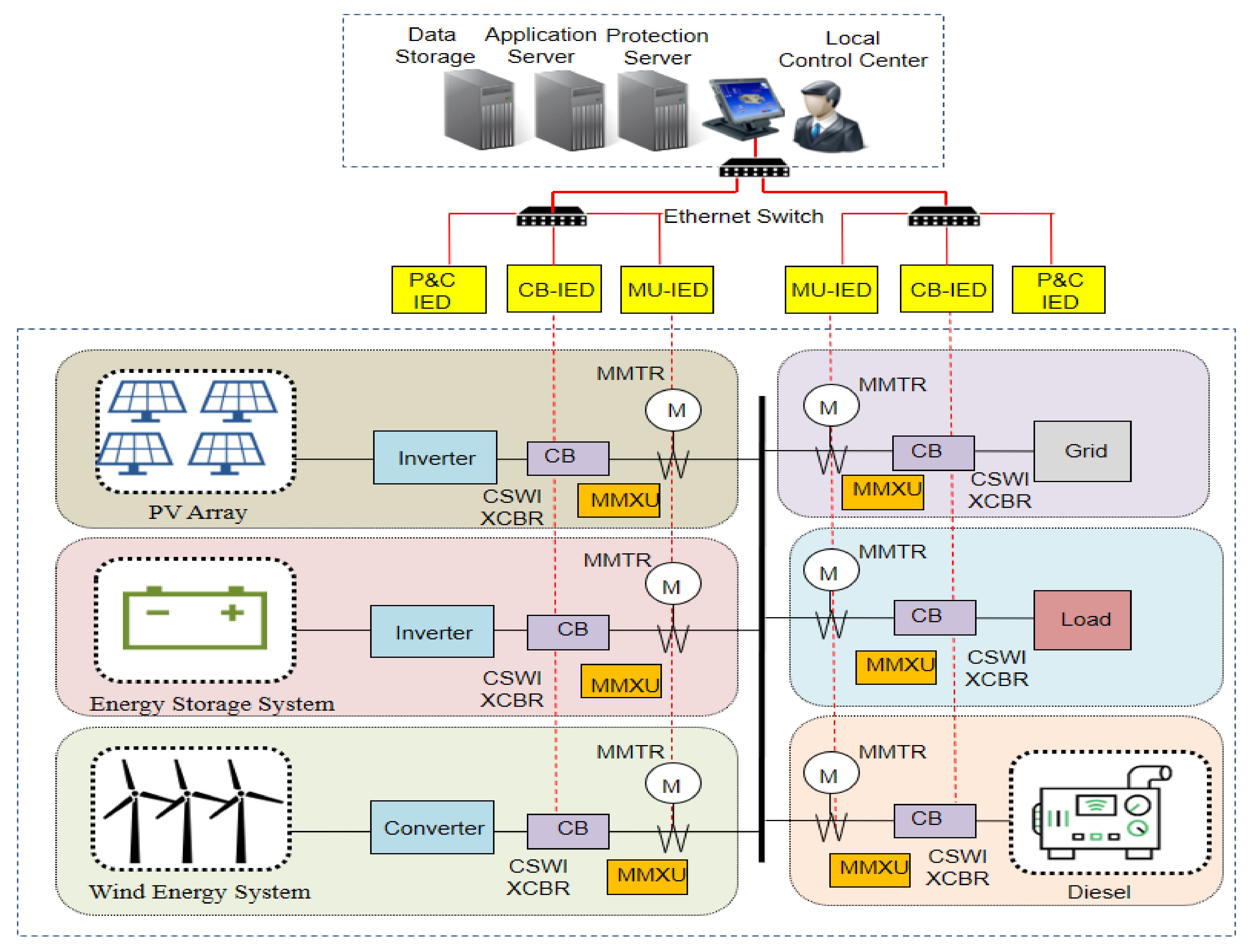
  • Propose a network model for the hybrid renewable energy system components, including wind turbine, PV system, energy storage, and diesel generator based on IEC 61850 standard.
  • The proposed network models include different data types such as analogue measurement, status information, and control information.
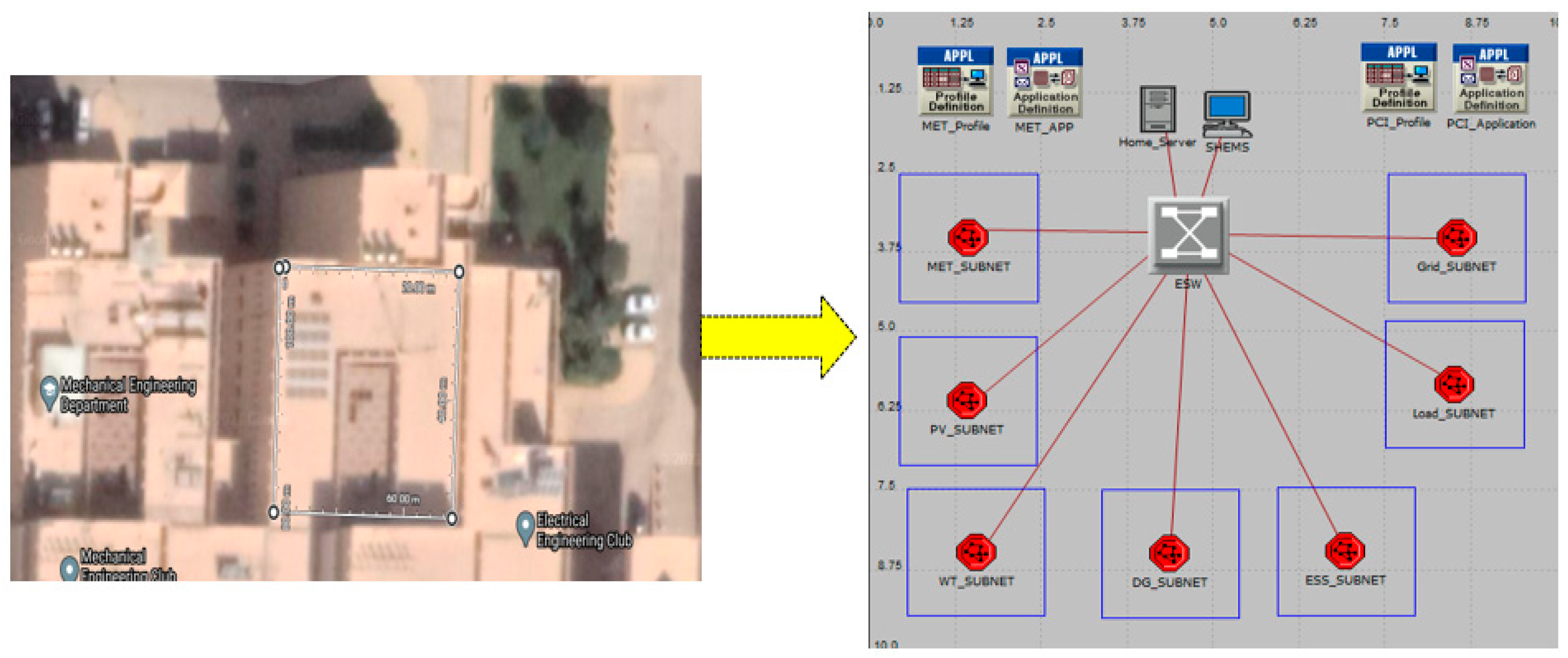
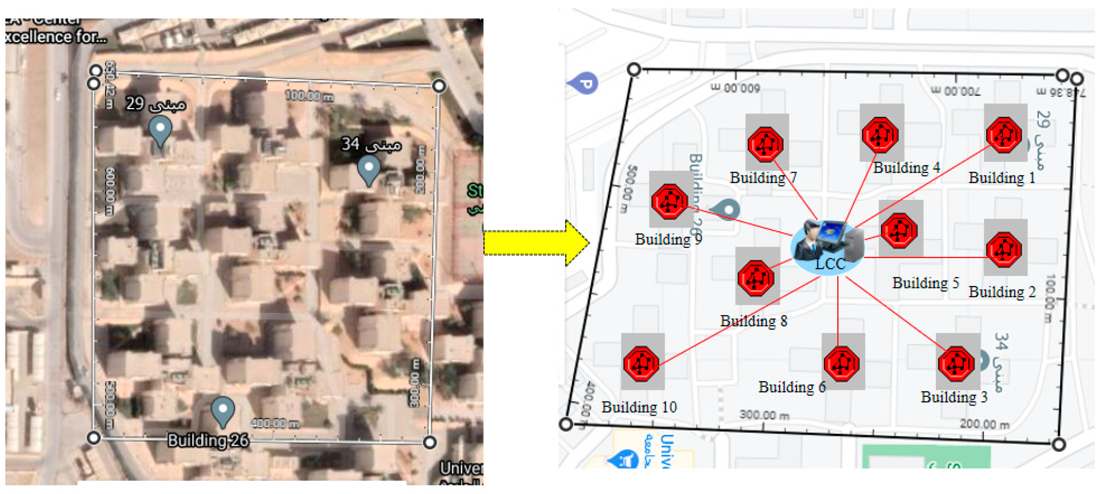
  • Performance evaluation of HRES with respect to network latency. A university campus in Saudi Arabia is considered as a case study.

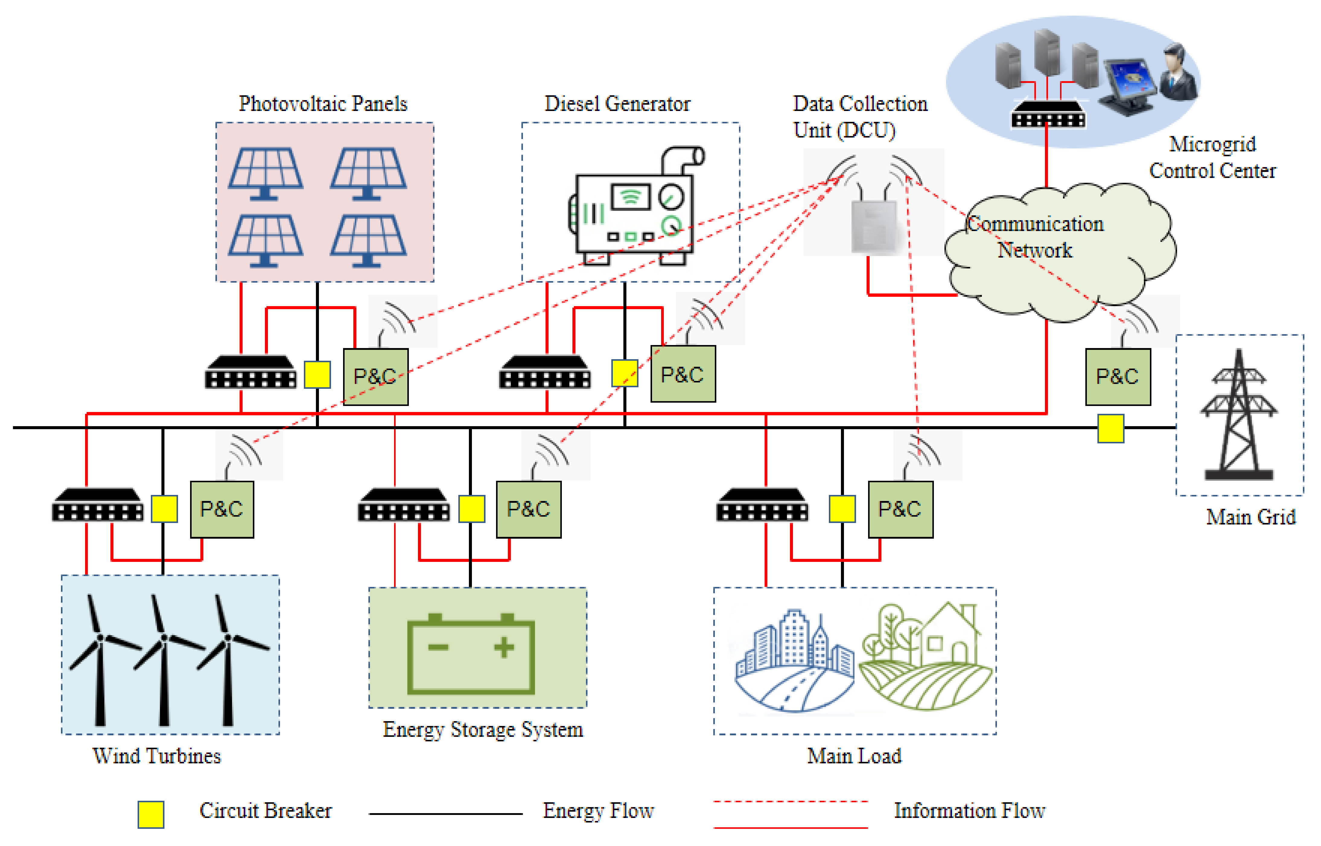
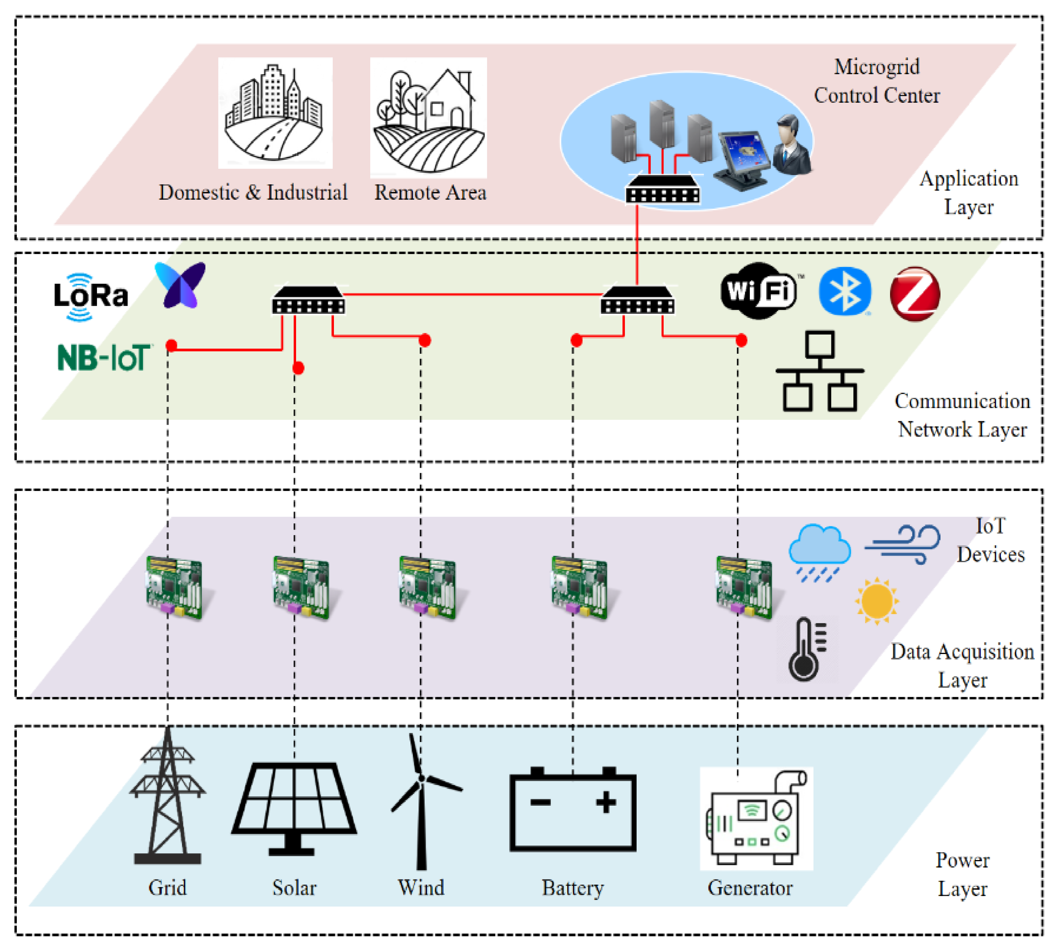
3. IoT-Based Architecture for Hybrid Renewable Energy System

In HRES, communication infrastructures are crucial elements that are responsible for data exchange among data resources (sensors and meters), controllers, and the control center. In order to support remote monitoring and control operation, the information flow from different entities defines the system architecture [19]. The IoT technology will provide great opportunities for sensing, communication, processing, and actuating to support various microgrid applications. First, measured data are acquired and transmitted to the local control center using a communication network. Then, decisions are made with this data, and control commands are sent through the communication network where the control commands are run using controllable devices. Two main types of communication schemes could be considered: centralized schemes and distributed schemes. In the centralized scheme, all data are transmitted to a central control center where data are processed and control commands are transmitted to controllable entities. In the distributed scheme, all data are received and processed using the local controller. In order to control the entire system, local control centers need to share information with each other through the communication network.
This work focuses on the communication level between the local controller of HRES and the microgrid control center, where the status of different renewable energy sources and loads can be collected and communicated to a central controller that determines an appropriate action in the system. Figure 2 shows the IoT-based architecture for HRES which consists of four main layers: the power layer, the data acquisition layer, the communication network layer, and the application layer [20,21,22,23].

3.1. Power Layer

The power layer covers residential power generation and consumption. Examples of power consumption are residential homes/buildings that include different applications such as heating, ventilation, and air conditioning (HVAC), lighting, electric vehicles, and various appliances. Residential energy generation consists of various renewable energy sources, such as wind and solar power, conventional sources, such as diesel generators, and energy storage systems, such as batteries. Other elements that are part of the power layer are transformers, buses, and loads. Loads could be classified into three main types: residential, commercial, and industrial. In addition, various sensor nodes, measuring devices, and actuators are attached to the power system layer.

3.2. Data Acquisition Layer

The data acquisition layer includes different types of sensor nodes and measurement devices connected to different subsystems of HRES. Data collected utilizing various sensor nodes and measurement devices is transmitted to the application layer through the communication network layer. Based on the data from different energy sources such as wind energy, photovoltaic system, diesel generator, and battery storage, HRES can be operated in island mode or grid-connected mode.

3.3. Communication Network Layer

The communication network layer is responsible for receiving the data from sensor nodes and measuring devices in the power layer and sending it to the control center. This can be done through various network services, including home area network (HAN), building area network (BAN), neighborhood area network (NAN), and wide area network (WAN). Based on the type of communication technology, the communication network can be divided into wired-based solutions (PLC, Ethernet, optical fibers, etc.) and wireless-based solutions (Wi-Fi, ZigBee, WiMAX, LoRa, Cellular, etc.). The communication network layer enables data collection and transmission from each system component using intelligent electronic devices (IEDs) and remote terminal units (RTUs). The data is stored in the control center for different services such as human-machine interfaces (HMI), application servers, historians, databases, and web servers.

3.4. Application Layer

The main function of the application layer is real-time monitoring and control. All monitoring data and status information are received, stored, and processed for different services at the local control center. The control center incorporates a local area network (LAN) which enables communication with different protection and control devices such as IEDs and RTUs. Examples of smart home/building applications are energy consumption management, environmental control, and HVAC management. Other applications for power service providers are DER management, demand response, and EMS. The control center coordinates the system operation by receiving and analyzing the monitoring data received from the communication network layer.

4. Modeling of Hybrid Renewable Energy System

HRES are designed to generate electric power using different power generation sources, such as small-scale wind turbines, photovoltaic systems and/or other conventional sources, such as diesel generators. These systems can support power ranging from a single house/building to a large system such as a village or an island. Based on the connection with the main grid, the system can be classified as in standalone mode or grid-connected mode [24]. In the case of the standalone mode, HRES should be designed to meet the required power demand. There are different configurations for the hybrid renewable energy system such as AC, DC, and hybrid AC/DC, based on the voltage of the main bus linking all assets. In the AC configuration, all assets are connected to an AC bus directly or via converts, while all assets are connected to a DC bus for the DC configuration [25].
In this work, the main components of HRES are energy sources (PV systems, wind turbines, diesel generators, and electric grids), energy storage system, and load. The selection of HRES elements is based on the scenario of Saudi Arabia because the electricity generation costs for isolated areas, such as mountainous, villages, and desert areas are expensive and face many challenges, such as difficult access to remote sites and low population density. Therefore, hybrid renewable energy generation would benefit such remote areas and reduce dependence on fossil fuels. Different standards have been considered for the information model of the hybrid energy system, such as IEC 61400-25, IEC 61850, and IEC 61850-7-420 [26]. The information model uses the logical node concept to represent the information model for a real device that needs to be exchanged with other devices and/or systems. Figure 3 shows the basic building blocks of the energy management system (EMS) for the hybrid energy system. It consists of two main parts: EMS sensing devices and EMS analytics.
The EMS sensing devices represent different sensor nodes, meters, and monitoring devices connected to HRES subsystems that are responsible for generating the monitoring data for the system. The EMS analytics aims to provide information about the system operation for the end-user based on the data received from EMS sensing devices. EMS solutions for HRES are different concerning types of sensors/measurements, short/long time scale monitoring, and targeted EMS analytics.
Figure 4 shows the modeling of HRES. Sensing devices represent sensor nodes and measuring devices connected to HRES to measure electrical and environmental parameters. Examples of these parameters are given in Table 3, Table 4, Table 5 and Table 6. Table 3 shows the sensing devices for the wind turbine system based on the IEC 61400-25-2 standard [27]. Based on the IEC 61400-25-2 standard, a wind turbine is represented as a virtual device that includes different logical nodes. Each logical node consists of different types of information, such as analogue measurements, status information, and control information. Ref. [28] gives a detailed description for network modeling of communication network architecture for the wind turbine system.
Table 4 shows the sensing devices for the photovoltaic system based on the IEC 61724 standard [27]. The operation of the PV system can be affected by different factors, such as shading, dust, cell damage, faults, and degradation. The amount of data generated from various sensor nodes is calculated based on the sampling frequency and the number of channels. Ref. [29] gives a detailed description for network modeling of communication network architecture for PV systems. In the case of small PV systems, the main parameters are voltage, current, power, irradiation, and ambient temperature.
The diesel generator is usually used as a backup if the wind turbines, PV systems, and battery storage systems are insufficient. The information model of the diesel generator includes functions and states of the engine characteristics such as status information, measured value, and control. The status information comprises engine status (ON/OFF) and measured values such as output power, fuel consumption, engine speed, etc. Table 5 shows the description of the logical nodes of the diesel system [30].
The battery storage system is used in case of an energy deficit. If there is an excess of energy produced, the batteries will be operating in charging mode. At the same time, if there is a deficit of energy produced, the batteries will be operating in discharging mode. In order to avoid undercharging and overcharging, the batteries are restricted with minimum and maximum storage capacities. Table 6 shows the description of the logical nodes of the battery system [30].
The selection of appropriate communication technology to support system performance as such delay and packet losses represents a challenging task. The delay requirements for different information types are given in Table 7 [32,33].

5. Simulation Results

The performance of the communication network for HRES is evaluated using OPNET Modeler. The HRES consists of wind energy, a conventional distributed generator (diesel generator), a photovoltaic system, a battery storage system, and loads. Wind energy and photovoltaic systems are among the most widely used renewable electricity generators to support smart home/building loads. The battery energy storage system is used to store the excess power generated from wind turbines and photovoltaic panels. During periods of higher-demand load (greater than the generated power), the battery systems are discharging and supporting the load.
Two scenarios are considered for grid integration of HRES in a university campus: Building Area Network (BAN) for a single building and Campus Area Network (CAN) for a group of buildings. We considered a system consists of a hybrid PV/wind/battery/diesel energy system. It is assumed that each building has a local building energy management system (BEMS), and the campus has a central campus control center (CCC). The communication network is responsible for receiving/transmitting the monitoring data among local controllers.
The measuring requirements for different sensor nodes, measuring devices, and IEDs of HRES are given in Table 8 and Table 9, respectively. Each component of HRES is modeled with different IEDs: a circuit breaker (CB-IED), a merging unit (MU-IED), and a protection and control (P&C-IED). The data generated from various IEDs is transmitted to the BEMS and/or local control center.

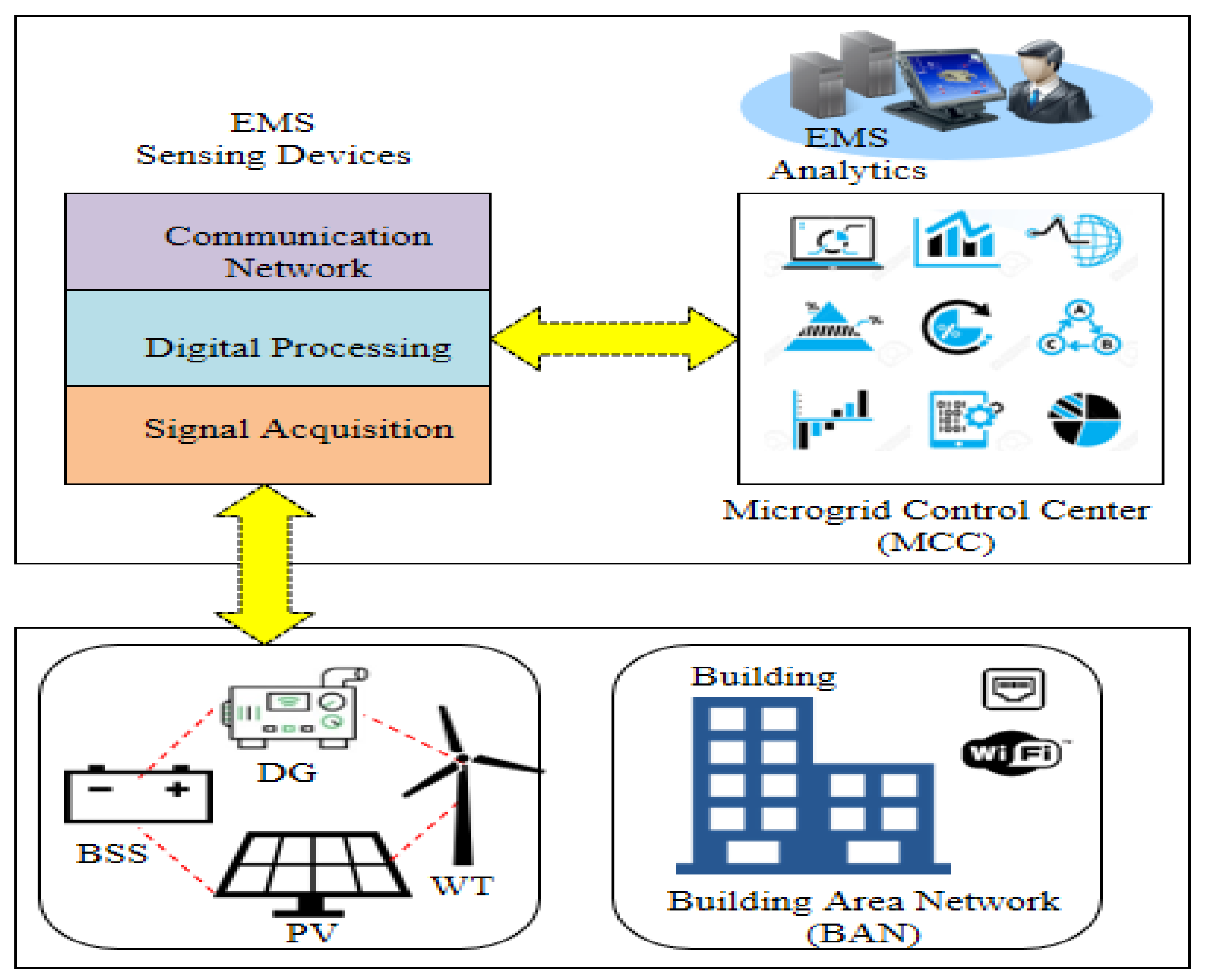
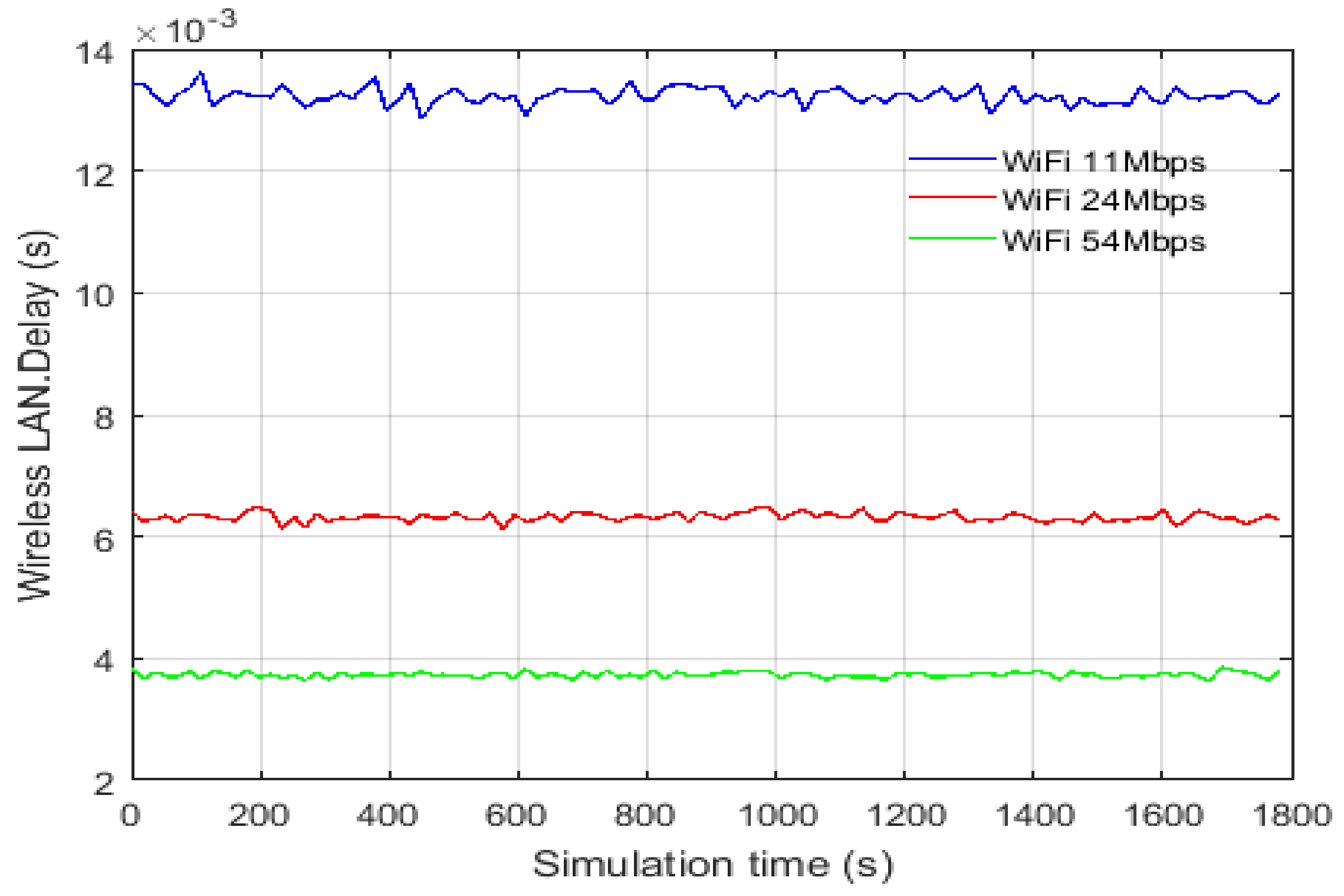
5.1. Building Area Network Results

Figure 5 shows the detailed communication network configuration of HRES for the smart building scenario. The communication network model is built in OPNET Modeler. The dimensions of the communication network model are 10 m × 10 m. The network configuration includes network setup, configure network traffic, packet size, start time and stop time, source, and destination. The communication network is configured as Ethernet LAN, consisting of 7 subnets: Grid_subnet, Load_subnet, ESS_subnet, Diesel_subnet, Turbine_subnet; PV_subnet; and Met_subnet. All subnets are connected to the building local control center via an Ethernet switch considering a star topology.
Each subnet is modeled using one CB-IED, one MU-IED, one P&C-IED, and one Ethernet switch. The data flow is between individual IEDs and the local control center. We considered two different communication technologies: Ethernet-based and Wi-Fi-based configurations with different data rates. The transmission line speed of Ethernet is configured with 10 Mbps, 100 Mbps, and 1 Gbps, while Wi-Fi-based configuration considered different data rates of 54 Mbps. 24 Mbps and 11 Mbps. The data flow between different subsystems and the building control center is configured as given in Table 10. The IED type, data type, and data size are given in Table 11.
The following metrics are considered for performance evaluation of the communication network: received traffic at the server (bytes/s) and end-to-end delay. The received traffic at the server compares the amount of received traffic with the amount of generated traffic. The Ethernet LAN delay represents the end-to-end delay of all packets received by all the sensor nodes. The wireless LAN delay represents the end-to-end delay of all packets received by the wireless LAN MACs of all WALN nodes in the network.
The network topology is configured as a star topology, where the data flow is mainly between individual controllers and the building control center. The impact of the communication technology for Ethernet-based architecture and Wi-Fi architecture is quantified with respect to latency and data rate. First, we validated the simulation models by comparing the amount of received traffic at the server. Each CB-IED transmits the status information to the building control center, where the message size is configured as 16 bytes. The voltage and current measurements are communicating through the MU-IED. The message size is configured as 76,800 bytes. The amount of data received are as follows: 2 bytes/s (temperature), 200 bytes/s (irradiance), 6 bytes/s (wind speed), 6 bytes/s (wind direction), 96 bytes/s (CB-IEDs), and 460,800 bytes/s (MU-IEDs). All data received correctly and consistently with the calculations.
The results of different scenarios configured for Ethernet-based and Wi-Fi-based architectures are given in Table 12 and Table 13. Table 12 shows the simulation results for the end-to-end delay over Ethernet LAN. The results show that the end-to-end delay is about 19.44 ms and 0.19 ms for channel capacity of 100 Mbps and 1000 Mbps, respectively. This indicates that Ethernet-based architecture can support the data transmission for HRES system at the building level. For Wi-Fi-based architecture, the results show that the end-to-end delay is about 3.86 ms and 13.62 ms for a data rate of 54 Mbps and 11 Mbps, respectively, as shown in Figure 6.

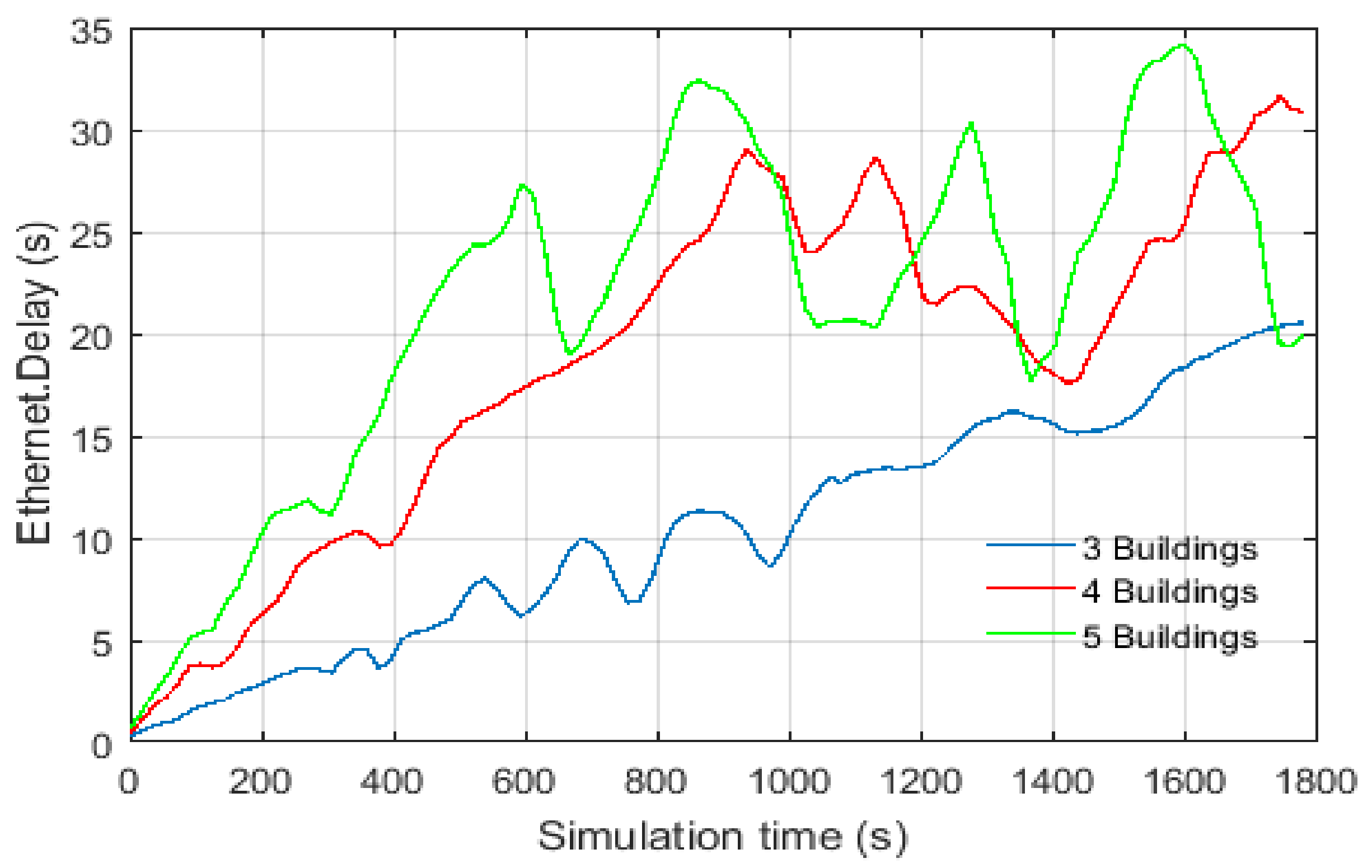
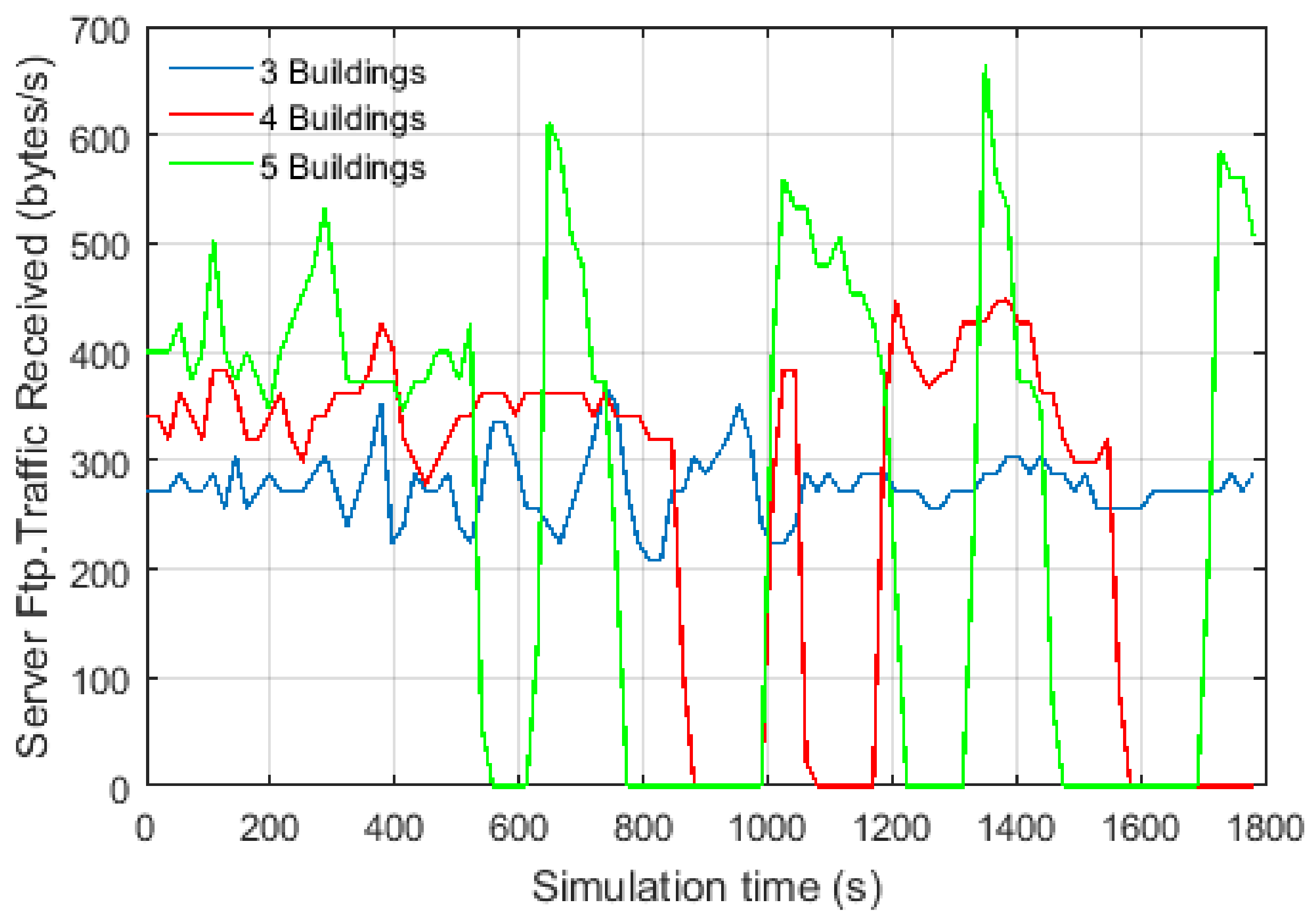
5.2. Campus Area Network Results

We considered different scenarios for a group of buildings on the university campus. We assumed that each building would be integrated with HRES that can be operated in a standalone mode or grid-connected mode. The dimensions of the network model are set as 100 m × 100 m. Different scenarios have been configured in the simulation with a different number of buildings. The communication network has been configured using Ethernet-based architecture. The configuration of the traffic flow is based on file transfer protocol (FTP). The network models have been validated by comparing the received amount of traffic at the server-side.
The results show that there is a loss of data and high end-to-end delay using the link capacity of 10 Mbps with the number of buildings is more than 3, as shown in Figure 7 and Figure 8. As a result, the configurations have been adjusted for using only Fast Ethernet (100 Mbps) and Gigabit Ethernet (1 Gbps). Table 14 summarizes the end-to-end delay with respect to the number of buildings. The OPNET model of the campus area network is shown in Figure 9. The results show that the communication network using Ethernet-based architecture with Fast Ethernet and Gigabit Ethernet can support the operation of HRES.
As discussed in this work, IoT technologies will play important roles in future energy supply using HRES. The main contributions of this study can be summarized in the following point:
  • This paper proposed a framework for IoT-based architecture for a hybrid energy system, which consists of four main layers: namely the power, the data acquisition, the communication network, and the application layers.
  • The framework studied the communication network associated with the grid integration of a hybrid energy system in a university campus consists of a small-scale wind turbine, PV system, diesel generator, and battery storage system.
  • The monitoring system has been defined based on the IEC 61850 standard, which consists of sensor nodes, data acquisition units, local control units, and a control center.
  • The OPNET Modeler has been used for network modeling and simulation of the developed communication network models.
  • The performance of the communication network model depends on different parameters such as the number of sensor nodes and measuring devices, number of given channels, data size, and sampling rate.
  • The simulation results showed the feasibility of Ethernet-based and Wi-Fi-based architectures for control and monitoring HRES.

6. Conclusions

This work presents an IoT-based architecture to support the grid integration of a hybrid renewable energy system in a university campus. The proposed architecture consists of four layers: the power, the data acquisition, the communication network, and the application layers. The communication models for the hybrid energy system consisting of a small-scale wind turbine, PV system, diesel generator, and battery storage system based on IEC 61850 standard, which is suitable for the isolated and small power system have been designed and implemented in different scenarios. The performance has been evaluated with respect to end-to-end delay using Ethernet-based and Wi-Fi-based communication architectures. The simulation results showed that the performance is sufficient for the operation using Fast Ethernet and Gigabit Ethernet, which ensures the latency requirements. This work contributes to the development of smart microgrid systems in Saudi Arabia and the integration of hybrid renewable energy systems.
The future work aims to complete the prototyping of HRES, implement the proposed architecture in a laboratory environment, and comparing the performance of the real prototype with the simulation models. Furthermore, network security and data transmission are among the most important issues that need to be considered including, cyber attacks and false data injection.

Author Contributions

Conceptualization, A.M.E. and M.A.A. (Mohamed A. Ahmed); Methodology, A.M.E. and M.A.A. (Mohamed A. Ahmed); Software, M.A.A. (Mohamed A. Ahmed); Validation, A.M.E., M.A.A. (Mohamed A. Ahmed), M.A.A. (Majed A. Alotaibi), and A.I.A.; Formal Analysis, A.M.E., M.A.A. (Mohamed A. Ahmed), M.A.A. (Majed A. Alotaibi) and A.I.A.; Supervision, A.M.E.; Project Administration, A.M.E.; Writing – Original Draft Preparation, A.M.E., M.A.A. (Mohamed A. Ahmed), M.A.A. (Majed A. Alotaibi) and A.I.A.; Writing – Review & Editing, A.M.E., M.A.A. (Mohamed A. Ahmed), M.A.A. (Majed A. Alotaibi) and A.I.A. All authors have read and agreed to the published version of the manuscript.

Funding

This work was supported by the deanship of scientific research at King Saud University, Saudi Arabia for funding this work through research group No (RG-1441-422).

Institutional Review Board Statement

Not applicable.

Informed Consent Statement

Not applicable.

Data Availability Statement

Not applicable.

Conflicts of Interest

The authors declare no conflict of interest.

Abbreviations

IoTInternet of Things
HRESHybrid Renewable Energy System
IECInternational Electrotechnical Commission
ICTInformation and Communication Technologies
DERDistributed Energy Resources
EMAEnergy Management Agent
SCADASupervisory Control and Data Acquisition
PLCProgrammable Logic Control
PVPhotovoltaic
PSOParticle Swarm Optimization
BABat Algorithm
WTWind Turbine
FCFuel Cell
BSSBattery Storage System
HVACHeating, Ventilation and Air Condition
LoRaLong Range
NB-IoTNarrow Band IoT
HANHome Area Network
BANBuilding Area Network
NANNeighborhood Area Network
WANWide Area Network
PLCPower Line communication
IEDIntelligent Electronic Device
RTURemote Terminal Unit
HMIHuman Machine Interface
LANLocal Area Network
EMSEnergy Management System
DGdiesel Generator
MCCMicrogrid Control Center
SDSensing Devices
CANCampus Area Network
BEMSBuilding Energy Management System
CCCCentral Control Center
CBCircuit Breaker
MUMerging Unit
P&CProtection and Control
LCLocal Controller
LCCLocal Control Center
GCGeneration Control
ESSEnergy Storage System
FTPFile Transfer Protocol

References

  1. Kabalci, Y.; Kabalci, E.; Padmanaban, S.; Holm-Nielsen, J.B.; Blaabjerg, F. Internet of Things Applications as Energy Internet in Smart Grids and Smart Environments. Electronics 2019, 8, 972. [Google Scholar] [CrossRef] [Green Version]
  2. Viswanath, S.K.; Yuen, C.; Tushar, W.; Li, W.-T.; Wen, C.-K.; Hu, K.; Chen, C.; Liu, X. System design of the internet of things for residential smart grid. IEEE Wirel. Commun. 2016, 23, 90–98. [Google Scholar] [CrossRef] [Green Version]
  3. Saleem, Y.; Crespi, N.; Rehmani, M.H.; Copeland, R. Internet of Things-Aided Smart Grid: Technologies, Architectures, Applications, Prototypes, and Future Research Directions. IEEE Access 2019, 7, 62962–63003. [Google Scholar] [CrossRef]
  4. Otero, C.E.; Haber, R.; Peter, A.M.; Alsayyari, A.; Kostanic, I. A Wireless Sensor Networks’ Analytics System for Predicting Performance in On-Demand Deployments. IEEE Syst. J. 2014, 9, 1344–1353. [Google Scholar] [CrossRef]
  5. Minoli, D.; Sohraby, K.; Occhiogrosso, B. IoT Considerations, Requirements, and Architectures for Smart Buildings—Energy Optimization and Next-Generation Building Management Systems. IEEE Internet Things J. 2017, 4, 269–283. [Google Scholar] [CrossRef]
  6. Islam, S.M.R.; Kwak, D.; Kabir, H.; Hossain, M.; Kwak, K.-S. The Internet of Things for Health Care: A Comprehensive Survey. IEEE Access 2015, 3, 678–708. [Google Scholar] [CrossRef]
  7. Elijah, O.; Rahman, T.A.; Orikumhi, I.; Leow, C.Y.; Hindia, M.N. An Overview of Internet of Things (IoT) and Data Analytics in Agriculture: Benefits and Challenges. IEEE Internet Things J. 2018, 5, 3758–3773. [Google Scholar] [CrossRef]
  8. Santos, P.M. PortoLivingLab: An IoT-Based Sensing Platform for Smart Cities. IEEE Internet Things J. 2018, 5, 523–532. [Google Scholar] [CrossRef]
  9. Bouhafs, F.; Mackay, M.; Merabti, M. Links to the Future: Communication Requirements and Challenges in the Smart Grid. IEEE Power Energy Mag. 2012, 10, 24–32. [Google Scholar] [CrossRef]
  10. Ku, T.-Y.; Park, W.-K.; Choi, H. IoT energy management platform for microgrid. In Proceedings of the 2017 IEEE 7th International Conference on Power and Energy Systems (ICPES), Toronto, ON, Canada, 1–3 November 2017; pp. 106–110. [Google Scholar]
  11. Setiawan, M.A.; Shahnia, F.; Rajakaruna, S.; Ghosh, A. ZigBee-Based Communication System for Data Transfer Within Future Microgrids. IEEE Trans. Smart Grid 2015, 6, 2343–2355. [Google Scholar] [CrossRef]
  12. Zia, M.F.; Benbouzid, M.; Elbouchikhi, E.; Muyeen, S.M.; Techato, K.; Guerrero, J.M. Microgrid Transactive Energy: Review, Architectures, Distributed Ledger Technologies, and Market Analysis. IEEE Access 2020, 8, 19410–19432. [Google Scholar] [CrossRef]
  13. Choi, J.S. Energy Management Agent Frameworks: Scalable, Flexible, and Efficient Architectures for 5G Vertical Industries. IEEE Ind. Electron. Mag. 2021, 15, 62–73. [Google Scholar] [CrossRef]
  14. Eltamaly, A.M.; Alotaibi, M.A.; Alolah, A.I.; Ahmed, M.A. A Novel Demand Response Strategy for Sizing of Hybrid Energy System With Smart Grid Concepts. IEEE Access 2021, 9, 20277–20294. [Google Scholar] [CrossRef]
  15. Tazay, A.F.; Samy, M.M.; Barakat, S. A Techno-Economic Feasibility Analysis of an Autonomous Hybrid Renewable Energy Sources for University Building at Saudi Arabia. J. Electr. Eng. Technol. 2020, 15, 2519–2527. [Google Scholar] [CrossRef]
  16. Kermani, M.; Carnì, D.L.; Rotondo, S.; Paolillo, A.; Manzo, F.; Martirano, L. A Nearly Zero-Energy Microgrid Testbed Laboratory: Centralized Control Strategy Based on SCADA System. Energies 2020, 13, 2106. [Google Scholar] [CrossRef]
  17. Abidi, M.G.; Ben Smida, M.; Khalgui, M.; Li, Z.; Qu, T. Source Resizing and Improved Power Distribution for High Available Island Microgrid: A Case Study on a Tunisian Petroleum Platform. IEEE Access 2019, 7, 22856–22871. [Google Scholar] [CrossRef]
  18. Sawle, Y.; Jain, S.; Babu, S.; Nair, A.R.; Khan, B. Prefeasibility Economic and Sensitivity Assessment of Hybrid Renewable Energy System. IEEE Access 2021, 9, 28260–28271. [Google Scholar] [CrossRef]
  19. Shahraeini, M.; Javidi, H.; Ghazizadeh, M.S. Comparison Between Communication Infrastructures of Centralized and Decentralized Wide Area Measurement Systems. IEEE Trans. Smart Grid 2010, 2, 206–211. [Google Scholar] [CrossRef]
  20. Stefanov, A.; Liu, C.-C. ICT modeling for integrated simulation of cyber-physical power systems. In Proceedings of the 3rd IEEE PES Innovative Smart Grid Technologies Europe (ISGT Europe), Berlin, Germany, 14–17 October 2012. [Google Scholar] [CrossRef]
  21. Abir, S.M.A.A.; Anwar, A.; Choi, J.; Kayes, A.S.M. IoT-enabled Smart Energy Grid: Applications and Challenges. IEEE Access 2021, 9, 50961–50981. [Google Scholar] [CrossRef]
  22. Shakerighadi, B.; Anvari-Moghaddam, A.; Vasquez, J.C.; Guerrero, J.M. Internet of Things for Modern Energy Systems: State-of-the-Art, Challenges, and Open Issues. Energies 2018, 11, 1252. [Google Scholar] [CrossRef] [Green Version]
  23. Wu, Y.; Wu, Y.; Guerrero, J.M.; Vasquez, J.C.; Palacios-Garcia, E.J.; Li, J. Convergence and Interoperability for the Energy Internet: From Ubiquitous Connection to Distributed Automation. IEEE Ind. Electron. Mag. 2020, 14, 91–105. [Google Scholar] [CrossRef]
  24. Bhandari, B.; Lee, K.-T.; Lee, G.-Y.; Cho, Y.-M.; Ahn, S.-H. Optimization of hybrid renewable energy power systems: A review. Int. J. Precis. Eng. Manuf. Technol. 2015, 2, 99–112. [Google Scholar] [CrossRef]
  25. Etamaly, A.M.; Mohamed, M.A.; Alolah, A. A smart technique for optimization and simulation of hybrid photovoltaic/wind/diesel/battery energy systems. In Proceedings of the 2015 IEEE International Conference on Smart Energy Grid Engineering (SEGE), Oshawa, ON, Canada, 17–19 August 2015; pp. 1–6. [Google Scholar]
  26. Ali, I.; Hussain, S. Communication Design for Energy Management Automation in Microgrid. IEEE Trans. Smart Grid 2016, 9, 1. [Google Scholar] [CrossRef]
  27. International Electrotechnical Commission (IEC). International Standard IEC 61400-25-2: Communications for Monitoring and Control of Wind Power Plants—Information Models, 1st ed.; International Electrotechnical Commission (IEC): Geneva, Switzerland, 2006. [Google Scholar]
  28. Ahmed, M.A.; Eltamaly, A.M.; Alotaibi, M.A.; Alolah, A.I.; Kim, Y.-C. Wireless Network Architecture for Cyber Physical Wind Energy System. IEEE Access 2020, 8, 40180–40197. [Google Scholar] [CrossRef]
  29. Eltamaly, A.M.; Ahmed, M.A.; Alotaibi, M.A.; Alolah, A.I.; Kim, Y.-C. Performance of Communication Network for Monitoring Utility Scale Photovoltaic Power Plants. Energies 2020, 13, 5527. [Google Scholar] [CrossRef]
  30. Yu, X.; Li, W.; Maleki, A.; Rosen, M.A.; Birjandi, A.K.; Tang, L. Selection of optimal location and design of a stand-alone photovoltaic scheme using a modified hybrid methodology. Sustain. Energy Technol. Assessments 2021, 45, 101071. [Google Scholar] [CrossRef]
  31. Zhang, W.; Maleki, A.; Pourfayaz, F.; Shadloo, M.S. An artificial intelligence approach to optimization of an off-grid hybrid wind/hydrogen system. Int. J. Hydrogen Energy 2021, 46, 12725–12738. [Google Scholar] [CrossRef]
  32. International Electrotechnical Commission. IEC 61850-7-420:2009: Communication Networks and Systems for Power Utility Automation—Part 7-420: Basic Communication Structure—Distributed Energy Resources Logical Nodes; International Electrotechnical Commission: Geneva, Switzerland, 2009. [Google Scholar]
  33. Serban, I.; Cespedes, S.; Marinescu, C.; Azurdia-Meza, C.A.; Gomez, J.S.; Hueichapan, D.S. Communication Requirements in Microgrids: A Practical Survey. IEEE Access 2020, 8, 47694–47712. [Google Scholar] [CrossRef]
Figure 1. Schematic diagram for grid integration of HRES. P&C: Protection and Control.
Sustainability 13 08555 g001
Figure 2. IoT-based architecture for smart hybrid energy system.
Sustainability 13 08555 g002
Figure 3. Energy management system for a hybrid renewable energy system.
Sustainability 13 08555 g003
Figure 4. Modeling of the hybrid renewable energy system.
Sustainability 13 08555 g004
Figure 5. OPNET model for building area network (BAN) scenario.
Sustainability 13 08555 g005
Figure 6. End-to-end delay for Wi-Fi-based architecture of the building area network scenario.
Sustainability 13 08555 g006
Figure 7. End-to-end delay for Ethernet-based architecture of the campus area network scenario.
Sustainability 13 08555 g007
Figure 8. Traffic received (bytes/s) for CB-IEDs with channel capacity of 10 Mbps for 3, 4 and 5 buildings scenario.
Sustainability 13 08555 g008
Figure 9. OPNET model for campus area network (CAN) scenario.
Sustainability 13 08555 g009
Table 1. Comparison among previous research work for the smart power grid.
Ref.
No.
TypeCyber-Physical Architecture LayerContribution
PowerSensorNetworkApplication
[1]surveyresidentialyesyesyesAnalyzed different IoT applications for smart grids such as smart homes, smart cities, smart meters, and management applications
[2]technicalresidentialyesyesyesStudied a large-scale IoT system for smart homes equipped with sensors, actuators, smart meters, and smart plugs
[3]surveysmart gridyesyesyesPresented a comprehensive survey on IoT-aided smart grids covering architectures, applications, and prototypes.
[11]technicalmicrogridyesyesyesPresented ZigBee based data communication for future microgrid applications
[12]surveymicrogridyesyesyesDiscussed the transactive energy concept and seven architecture layers for designing the transactive energy system
[21]surveysmart gridyesyesyesPresented a survey on IoT-based smart grids, including architectures, standards, and security.
[22]surveysmart gridyesyesyesPresented a general overview of IoT-based energy systems concerning key features, privacy, and challenges.
[23]surveymicrogridyesyesyesDiscussed the role of IoT-based microgrids, vertical convergence, energy platforms, and horizontal interoperability.
[14]technicalmicrogridnononoProposed a novel demand response for sizing HRES based on techno-economic objectives using different optimization techniques
[15]technicalmicrogridnononoProvided a techno-economic feasibility study of HRES to support energy for a university building in Saudi Arabia
[17]technicalmicrogridnononoFocused on optimizing the microgrid system to achieve a balance between production sources and load requirements.
[18]technicalmicrogridnononoPresented a feasibility economic and sensitivity assessment of HRES for isolated urban electrification in India.
[24]surveymicrogridnononoPresented a review of optimization HRES and physical modeling for wind turbines, PV systems, and engine generators.
[25]technicalmicrogridnononoPresented a design of a general program for sizing and optimizing a standalone hybrid wind/PV/diesel/battery system in Saudi Arabia.
[26]technicalmicrogridyesyesyesPresented the communication design for energy management automation in a microgrid system using Ethernet-based architecture.
[28]technicalwind farmyesyesyesPresented the communication design for monitoring a wind turbine using different technologies: Ethernet, Wi-Fi, ZigBee, and WiMAX.
[29]technicalPV farmyesyesyesPresented the communication design for a utility-scale photovoltaic power plant.
[30]Technicaloff-grid PV systemnononoPresented a framework for the selection of optimal location and optimal capacity of a remote standalone PV system.
[31]technicaloff-grid hybrid systemnononoProposed an optimization approach for long-term capacity planning of HRES composed of wind, fuel cell, and hydrogen storage system.
present worktechnicalmicrogridyesyesyesThis work proposes an IoT architecture for hybrid wind/PV/diesel/battery in a university campus.
Table 2. Monitoring scope of HRES.
LevelCoverageMonitoring ScopeControl DecisionTechnology
local controlLAN, BANHRES subsystem including solar, wind, battery, generator, gridlocalZigBee, Wi-Fi, Ethernet, etc.
area controlNANgroups of HRESlocal, distributedWi-Fi, Ethernet, etc.
central controlWANlarge scale HREScentralLoRa, NB-IoT, 4G, LTE, etc.
Table 3. Sensing devices for wind turbine system.
UnitPartSensing Devices (SD)
wind turbine
system
rotorrotor speed, rotor position, pressure temperature, pitch angle, status
transmissionvibration, oil level, temperature, grease level, pressure, status
generatorpower, temperature, speed, current, voltage, status
convertercurrent, voltage, power factor, torque, frequency, temperature, status
transformercurrent, voltage, oil level, temperature, status
nacelleorientation, wind Direction, wind speed, displacement, status
yawposition, speed, temperature, grease level
towerhumidity, status
meteorologicalwind Speed, wind direction, humidity, temperature, pressure
Table 4. Sensing devices for photovoltaic system.
UnitPartSensing Devices (SD)
PV systemPV arrayvoltage, current, power, module temperature, tracker tilt angle, tracker azimuth angle
gridutility voltage, current to grid, current from grid, power to grid, power from grid
meteo mastirradiance, ambient air temperature, wind speed, wind direction
Table 5. Sensing devices for diesel system.
UnitLNDescription
diesel systemDGENstatus of generator
DEXCstatus of the excitation components
MPRSpressure measurements
DSFCspeed or frequency controller
Table 6. Sensing devices for battery system.
UnitLNDescription
battery systemZBATremote monitoring & control of battery system
ZBTCremote monitoring & control of battery charger
ZRCTcharacteristics of the rectifier
Table 7. Requirements for data transmission.
Data TypeIEC 61850ETSI SG Protocol
protection4 ms1–10 ms
monitoring1 s1 s
control16–100 ms100 ms
operation & maintenance1 sNot specified
Table 8. Measuring requirements for meteorological data.
MeasurementSampling FrequencyNumber of ChannelsData Rate
ambient temperature1 Hz12 bytes/s
irradiance100 Hz1200 bytes/s
wind speed3 Hz16 bytes/s
wind direction3 Hz16 bytes/s
Table 9. IEDs configurations for HRES.
ComponentsCB-IEDMU-IEDP&C IED
PV system111
wind energy system111
energy storage system111
diesel generator111
load111
Table 10. Monitoring scope and control decisions.
LevelScopeConnectivity
load controllermonitoring and control loadLC→LCC
protection IEDscontrol & protectionIED→LCC
generation controlcontrol outputGC→LCC
storage controlcontrol charge/dischargeESS→LCC
load controllermonitoring and control loadLC→LCC
Table 11. IEDs configuration.
IED TypeData TypeData Size
CB IEDbreaker status16 bytes
MU IEDvoltage and current76,800 bytes
P&C IEDcontrol76,816 bytes
Table 12. End-to-end delay (ms) for Ethernet-based architecture for a standalone building.
Channel CapacityEthernet
10 Mbps
Ethernet
100 Mbps
Ethernet
1000 Mbps
one building19.441.920.19
Table 13. End-to-end delay (ms) for Wi-Fi-based architecture for a standalone building.
Channel CapacityWi-Fi
11 Mbps
Wi-Fi
24 Mbps
Wi-Fi
54 Mbps
MinMaxMinMaxMinMax
one building12.8513.626.126.483.633.86
Table 14. End-to-end delay (ms) for Ethernet-based architecture.
ScenarioEthernet
10 Mbps
Ethernet
100 Mbps
Ethernet
1000 Mbps
1 building19.73 ms1.91 ms0.19 ms
2 buildings39.36 ms3.83 ms0.39 ms
3 buildings--5.82 ms0.58 ms
4 buildings--7.78 ms0.78 ms
5 buildings--9.71 ms0.98 ms
6 buildings--11.83 ms1.17 ms
7 buildings--13.68 ms1.37 ms
8 buildings--15.91 ms1.57 ms
9 buildings--17.95 ms1.78 ms
10 buildings--19.74 ms1.97 ms
Publisher’s Note: MDPI stays neutral with regard to jurisdictional claims in published maps and institutional affiliations.

