1. Introduction
The rapid development of the global economy continues to have a negative impact on the global energy and sustainability sectors. Increases in energy demand and consumption mean that environmental pollution and the energy crisis have become serious issues [
1]. In order to overcome such problems, revolutionary innovations are needed in electrical power generation systems. The development of alternative energy technologies, such as wind and solar-based energy generation systems, is receiving worldwide attention [
2]. As an example, California plans to supply 33% of its needed energy from renewable energy sources in 2020 [
2]. In addition, the European Parliament aims to generate 20% of the EU’s total energy needs by renewable energy in 2020 [
3]. Despite the promising future for the development of renewable energy sources, the uncertainty and unreliability of generation systems still create other challenges, such as the problem of integrating renewable energy systems into electrical power grids, which is difficult because of their intermittent characteristics [
4]. Installation of energy storage systems (ESSs) has been proven to reduce the fluctuations of renewable energy sources [
5]. Moreover, the recent increased number of electric vehicles (EVs) has led several researchers to investigate using EVs to diminish the fluctuation of renewable energy sources [
6].
Recently, the increased use of EVs has modified the transportation sector. EVs can contribute to reductions in fossil fuel usage [
7]. Considering the maximum capacity of EV batteries, EVs can be employed as flexible energy storage systems. For example, the Nissan Leaf model has a 30 kWh maximum capacity, and the Tesla Model-S has an 85 kWh maximum capacity [
8], which can escalate power systems’ flexibility. EVs also can be integrated into microgrid (MG) systems by extending the vehicle-to-grid concept [
9]. In this circumstance, EVs can act as distributed generation (DG) sources to provide power for MGs or as loads to absorb power from MGs. However, connecting EVs to MGs has inherent uncertainties related to the connection and disconnection times as well as the initial state-of-charge (SOC) of an EV battery when an EV is first connected to an MG. Due to these uncertainties, integrating EVs into MGs has become a more critical and challenging issue.
An MG is an electric power system interconnected with renewable energy sources, ESSs, and loads in a specific area. Based on the bus voltage type, MGs can be categorized into three categories: AC microgrids (ACMGs), DC microgrids (DCMGs), and hybrid AC-DC microgrids (AC-DCMGs). Recently, DCMGs have been preferred to ACMGs due to their lack of frequency stability issues, current harmonics, phase imbalances, and reactive power [
10]. In addition, since the process of integrating DG sources into a DCMG system is more straightforward in comparison to ACMGs, DCMGs are constructed more effectively [
11,
12]. As a result, recent research interest in MGs has been primarily focused on the DCMG system.
An MG can operate either in the grid-connected mode or the islanded mode as an autonomous system [
13]. By injecting or absorbing power from the MG based on electricity pricing policies, such as the real-time price (RTP), time-of-use (TOU) price [
14], and stepwise-power-tariff (SPT) method, the grid can support an MG if it is available. TOU pricing divides electricity prices into peak-valley and peak-normal-valley periods. In contrast, the RTP divides electricity costs into high-cost and low-cost periods and has higher fluctuations in price than the TOU [
15]. Meanwhile, the SPT method is employed for energy saving in China. The SPT method divides the monthly electricity price into several levels based on the electric power consumption [
16].
As grid outages become more frequent and serious due to the increasing frequency of extreme weather conditions, the reliability of main grids will continue to reduce [
17]. To maintain the power quality under these conditions, adequate coordination between MG systems and main grids is required. MG control schemes are divided into three categories in terms of coordinating power agents: the centralized control scheme, decentralized control scheme, and distributed control scheme [
18]. The decentralized control method is known to have the highest flexibility and scalability among the three schemes. All power agents decide on their operating modes independently without information from the other agents in this scheme. However, it is difficult to achieve an optimum solution in this scheme due to the lack of coordination between the power agents [
19]. In the distributed control scheme, the local information of MG agents is shared among their neighbors, which choose their operating modes based on this shared, external information as well as other internal information. Thanks to the existence of these communication links, this scheme has the possibility to reach the local optimum solution. On the other hand, in the centralized control scheme, all the power agents communicate with the central controller (CC), and therefore all agents determine their operating modes according to data obtained from the CC. Amongst those three control schemes, only the centralized control scheme could achieve a global optimum solution under multiple constraints by constructing an effective energy management system (EMS) alongside the CC in the MG system [
20].
In general, the EMS uses the prime objective function of the MG to decide the MG agent operating modes. In [
21], the home economy is maximized using the convex programming for the smart home system with ESS and photovoltaic (PV) power generation using a 1-day time period. Total cost minimization for annual operation cost and annual investment cost of a smart home with ESS and PV has been researched based on the stochastic and deterministic methods by three different pricing methods using a 1-year time period in [
22]. An EMS can also solve a multi-objective problem of the MG such as the combination of minimizing the energy cost and the peak-to-average ratio (PAR) in total load [
23]. However, integrating EVs into MGs makes the objective function more complex. The optimization of EV batteries’ lifespan [
24] and EV charging schedules [
25] are common examples of selecting the objective function to provide the benefit for the EV owners in the MG system connected with EVs. To utilize the flexible potentials of EVs, several researchers have developed a parking lot MG with EV connections [
26,
27]. A study in [
28] investigates the coordination of integrated energy systems and an EV charging station in multiple stakeholder scenarios. Another study in [
29] implements the multiple model predictive control (MMPC) methods in EVs to improve the frequency stabilization in the MG. The minimization problem applied to the total energy consumption cost is also investigated for vehicle-to-grid (V2G) microgrid systems considering a multi-objective function [
30]. The research in [
31] describes the co-benefit of EV and V2G systems. However, a typical EMS is designed to achieve only one objective function for either the MG or EV system. Thus, particular consideration is required in the MG system to select a preferable objective function.
Although several researchers have investigated the MG behavior caused by the EV connections, none of them have considered the uncertainties of EVs, DG power, electricity price conditions, and the unreliable grid connection altogether. Moreover, a straightforward algorithm is preferred to reduce the computational burden in the CC and implement it easily in the real system. Motivated by the problems mentioned above, this paper presents a centralized power flow control scheme of EV-connected DCMG to satisfy multi-objective problems under several constraints. By considering a grid agent, wind power agent, EV agent, load agent, and battery agent as DCMG components, a reliable and optimized DCMG system capable of satisfying the selected prime objective function is constructed in this study. For this aim, two prime objective functions are presented to provide the benefit to the DCMG system or the EV owners. Minimizing the electricity cost may be chosen as the prime objective function to benefit the DCMG system, while maximizing the EV SOC may be selected to benefit the EV owners. Moreover, the developed power flow control algorithm works stably even under the uncertainties of power generated from the wind power agent, EV connection and disconnection times, initial SOC level of the EV battery, and the grid availability. Because the power flow control is achieved based on the centralized control scheme, the CC decides the operation modes for each agent in the MG based on their overall local agent data. The operating modes of the agents are decided by using information regarding the EV connection/disconnection status to the DCMG, the initial SOC value of the EV, the generation of the wind power agent, the battery SOC level, and the DCMG operation status either in the grid-connected mode or islanded mode. In addition to these conditions, the electricity price conditions, and DCMG prime objective, are also used to decide the operating modes of each power agent in DCMG.
To prove the feasibility of the proposed power flow control scheme, the Powersim (PSIM) software (9.1, Powersim, Rockville, MD, USA) is used in this work to carry out the simulation [
32]. This software has been used to simulate a microgrid system in several works [
10,
18,
20,
33]. The simulation setups validate that the proposed scheme regulates the DC-link voltage stably and reliably regardless of a sudden EV connection and disconnection with the DCMG, even when the prime objective of the DCMG operation is immediately changed, or the electricity price conditions are varied. Ultimately, the experiments under the same conditions have been carried out using the prototype DCMG system to prove the simulation results. The contributions made by this study are summarized as follows:
The power flow control structure of an EV-connected DCMG is presented. The proposed control scheme guarantees the stability of the DC-link voltage under uncertainties of EV, power generation, grid availability, and electricity price conditions.
A power flow control scheme that provides benefits to the DCMG system or the EV owners is proposed. Depending on the selection of the prime objective function, the EV battery SOC can be maximized, or the electricity cost can be minimized. Despite the DCMG prime objective change, the proposed scheme ensures a stable and smooth DCMG operation without any severe transience.
The proposed scheme is simple and easy to implement in the real system. The feasibility of the proposed scheme is validated with the experimental testbed consisting of practical power electronics converters.
The rest of the paper is structured as follows:
Section 2 presents a configuration of an EV-connected DCMG system.
Section 3 proposes the power flow control strategy for the EV-connected DCMG system in both the grid-connected mode and islanded mode.
Section 4 and
Section 5 demonstrate the effectiveness of the present work based on simulation and experiment results, respectively. Finally, conclusions are presented in
Section 6.
2. Configuration of EV-Connected DCMG System
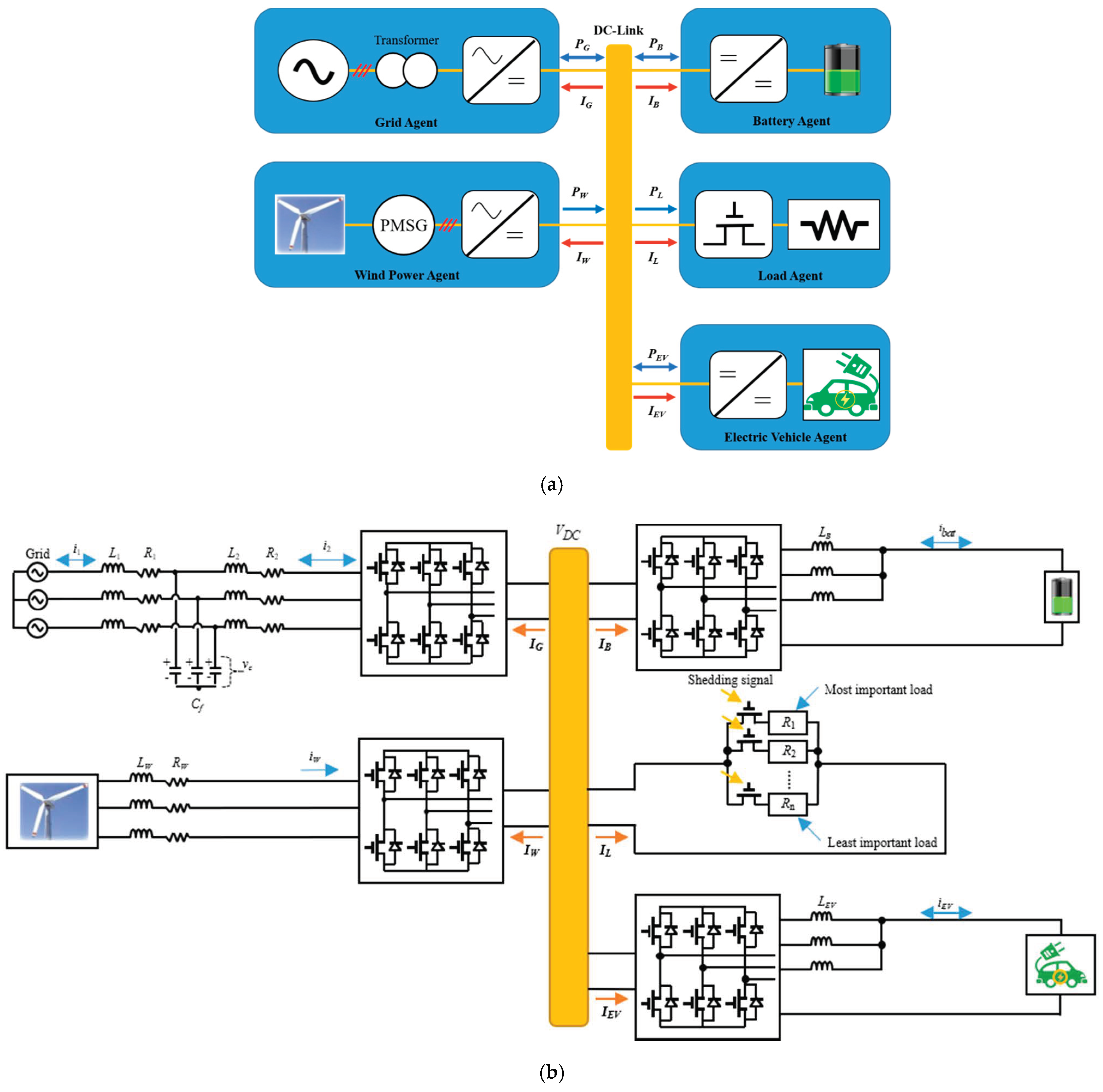
Figure 1 shows a configuration of the DCMG system with EV and grid connections.
Figure 1a shows a structure of a DCMG, in which the DCMG system is composed of different sources such as grid, battery, wind, load, and EV agents. The DCMG system in
Figure 1 can be extended into a larger system with multiple renewable energy sources, batteries, loads, and EVs. The reference direction of current is also shown in this figure, in which the current that flows into the DC-link is denoted as negative (−) current. In contrast, the current that flows out of the DC-link is denoted as positive (+) current. In
Figure 1a,
PG denotes the power exchange between the DC-link and grid agent,
PB denotes the power exchange between the DC-link and battery agent,
PEV denotes the exchange power between the DC-link and EV agent,
PL is the power absorbed in the load agent, and
PW is the power generated by the wind power agent. A grid-connected inverter and transformer are installed to exchange the power between the grid agent and the DCMG. A bidirectional DC-DC converter is employed in the battery and EV agent systems in order to connect those systems to the DC-link. The wind turbine is connected with a unidirectional AC-DC converter and a permanent magnet synchronous generator (PMSG) to inject the generated power into the DCMG system. Load shedding and reconnection are carried out in the load agent by switching the electronic switches.
Figure 1b shows a detailed configuration of the DCMG system with EV and grid connections. The grid-connected inverter uses an inductive-capacitive-inductive (LCL) filter to reduce the switching harmonics in the grid-side currents in the grid agent. The filter resistances, filter inductances, and filter capacitance are denoted by
R1,
R2,
L1,
L2, and
Cf, respectively. In addition,
i1 and
i2 represent the grid-side current and inverter-side current, respectively. In the grid-connected mode of the DCMG, the grid agent operates with three operating modes. When the grid agent supplies the power from the main grid into the DCMG system to support the DC-link voltage, the grid agent operates in the DC-link voltage control converter (VDC CON) mode. The grid agent also works in the inverter mode (VDC INV), in which the grid agent regulates the DC-link voltage by injecting the surplus power from the DCMG system into the main grid. The remaining operation of the grid agent is the IDLE mode in which the grid agent and DCMG system are interconnected without any power exchange.
Two bidirectional interleaved buck-boost DC-DC converters are installed to connect the DCMG system with the battery agent and the EV agent through an inductive (L) filter. The battery and EV agents have five operating modes: two voltage control modes, two current control modes, and the IDLE mode. The DC-link voltage control by discharging (VDC D) mode is the first one, in which the battery and EV agents control the DC-link voltage by supplying the discharging power into the DC-link. On the contrary, the agent operating mode is the DC-link voltage control by charging (VDC C) mode, if the DC-link voltage is maintained by charging the battery or EV agent with the surplus power. Two current control modes are charging with the maximum allowable power (Max C) and discharging with the maximum allowable power (Max D). The last operating mode of the battery and EV agents is the IDLE mode in which the power does not exchange between these agents and the DC-link. In
Figure 1b,
LB and
LEV represent the filter inductances of the battery and EV agents, respectively, and
ibat and
iEV denote the battery and EV currents, respectively.
An L filter is also employed in the wind power agent to connect the PMSG and unidirectional AC-DC converter. In
Figure 1b,
LW and
RW are the filter inductance and resistance parameters, while
iW denotes the phase current of the PMSG. There are two operating modes in the wind power agent. The first operating mode is the maximum power point tracking (MPPT) mode, in which the wind power agent maximally extracts power from the wind turbine. The next operating mode is the DC-link voltage control (VDC) mode. This mode occurs in the condition that the generated power from the wind power agent
PW is greater than the demand load power
PL, and any other agents cannot absorb the surplus power of the DCMG system. In this situation, the nominal DC-link voltage should be maintained by reducing
PW.
Whenever the load power is higher than the available power in DCMG, the load agent commences load shedding (SHD) mode to prevent the DCMG system from collapsing by eliminating the unnecessary load. In this operation, the least important loads are first disconnected until the power balance in the system is guaranteed. When the grid is reconnected to the DCMG or the battery/EV agents have sufficient SOC level, shedded loads are reconnected by the load reconnection (RECON) algorithm.
Table 1 shows the summary of the operating modes of each power agent for the EV-connected DCMG. To ensure a DCMG operation, the reliable control of power electronics converters is an indispensable part. To effectively realize all the operating modes by each power agent in
Table 1, power converter controllers are implemented by modifying the configuration in [
20].
3. Proposed Power Flow Control Strategy of EV-Connected DCMG
The proposed power flow control strategy of the EV-connected DCMG is determined based on the correlation between the generated power and demanded power. The power balance equation for this study is described in (1). To avoid the grid, battery, and EV agents operating in two operating modes at the same time, the constraints are added in (2)–(5) and (8)–(9), respectively. Additionally, the power limit for the battery and EV agents are expressed in (6)–(7) and (10)–(11) as follows:
where:
- PG,CON:
power injected from grid in converter operation;
- PG,INV:
power absorbed by grid in inverter operation;
- PB,dis:
battery discharging power;
- PB,char:
battery charging power;
- PEV,dis:
EV discharging power;
- PEV,char:
EV charging power;
- xG,CON, xG,INV, xB,dis, xB,char, xEV,dis, and xEV,char:
binary variables.
To decide the operating modes of power agents, the CC exchanges the data with power agents in the proposed scheme. The crucial factors that determine power agents’ operations are as follows: the grid availability, the EV connectivity to DCMG, SOC levels of the battery and EV, the available power of the wind power agent, the electricity cost condition, and the DCMG prime objective. The CC considers these factors in order to send the data regarding the operating modes to all power agents. According to the grid availability, the proposed EV-connected DCMG is mainly divided into power flow structures in grid-connected and islanded modes.
3.1. Power Flow Control of DCMG with EV and Grid Connection
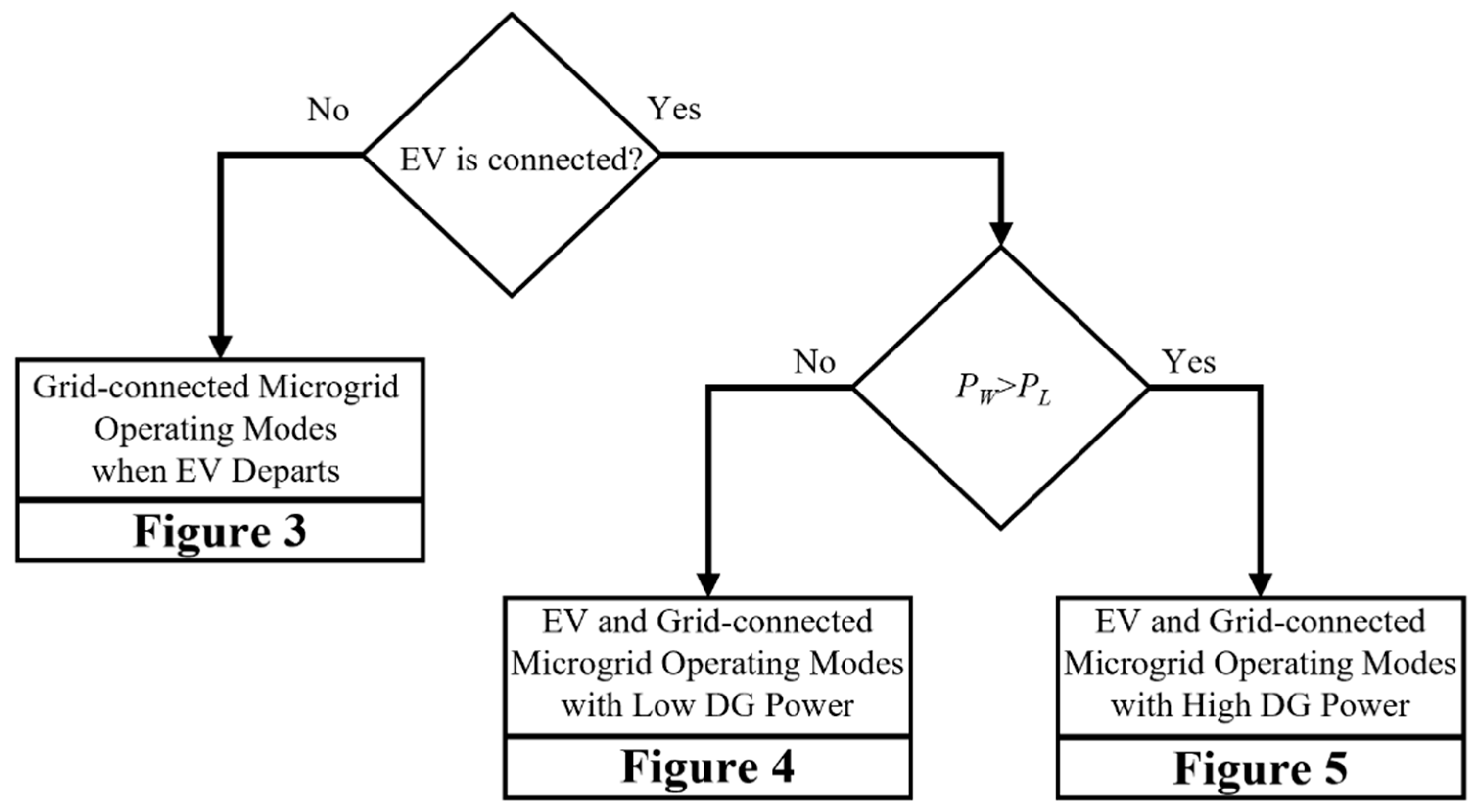
Figure 2 shows the power flow control strategy of the DCMG with EV and grid connections, which is developed to consider several uncertainty factors. Even if the proposed power flow control strategy is developed considering only the wind turbine as a renewable energy source, it can be easily extended by introducing the term of the total DG power,
PDG, instead of
PW when other renewable energy sources are used interconnected into the DCMG system. According to the existence of EV in the DCMG, the power flow control in
Figure 2 is classified into three main groups. The first category is the power flow control strategy when EV departs from the DCMG. This power flow control strategy is represented in
Figure 3 in detail. With the EV connections into the DCMG, the power flow control strategy is further divided into two groups according to the generation power of the DG,
PW.
Figure 4 and
Figure 5 show the power flow control schemes for the remaining two groups, in which
Figure 4 represents the case when
PW is less than
PL, while
Figure 5 represents the case when
PW is greater than
PL.
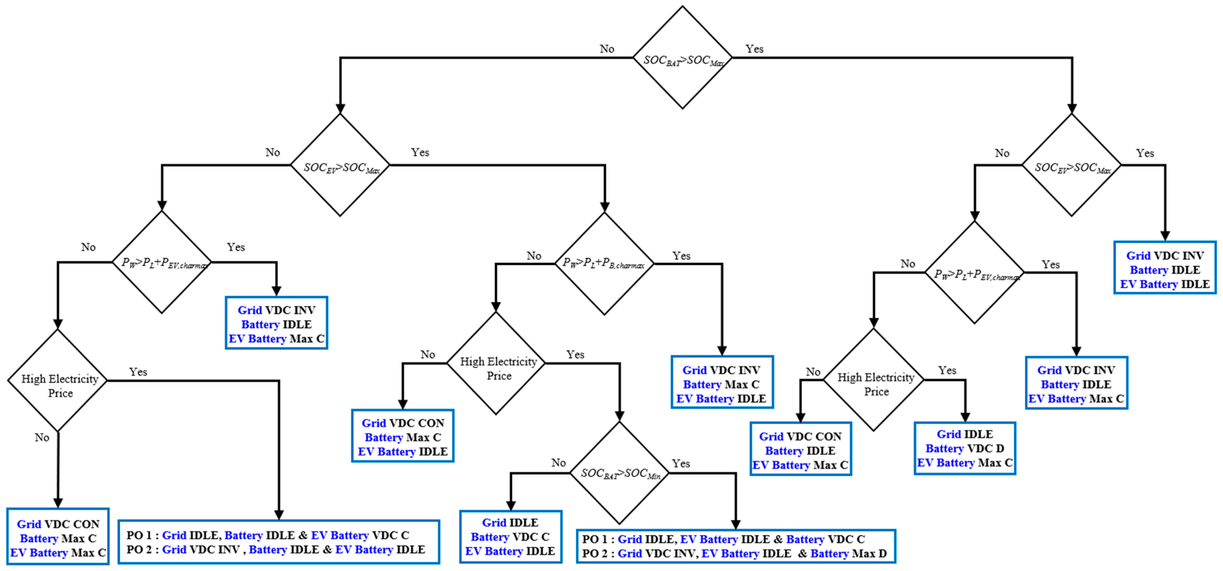
In the control strategy of the DCMG with EV and grid connections, as shown in
Figure 3 through
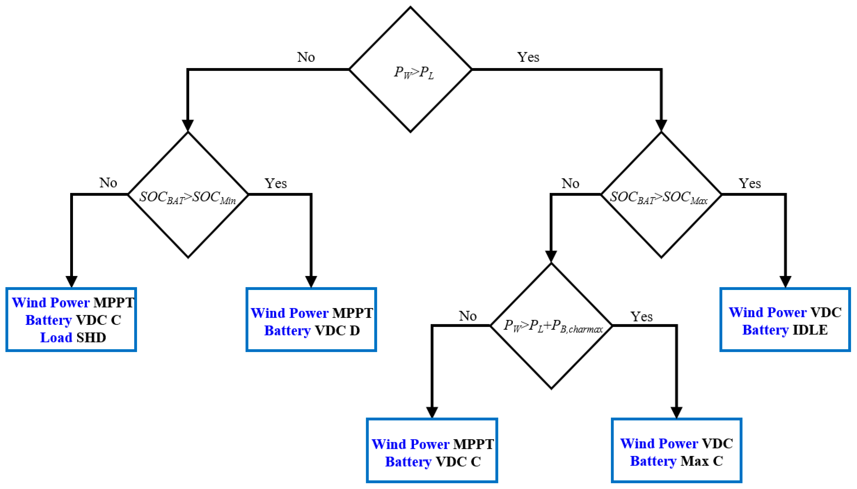
Figure 5, the wind power agent is always operated in the MPPT mode. As a result, the wind power agent operating mode is not described in these figures. The other agents’ operating modes are decided by the operating conditions of the agents, constraints, and DCMG prime objective.
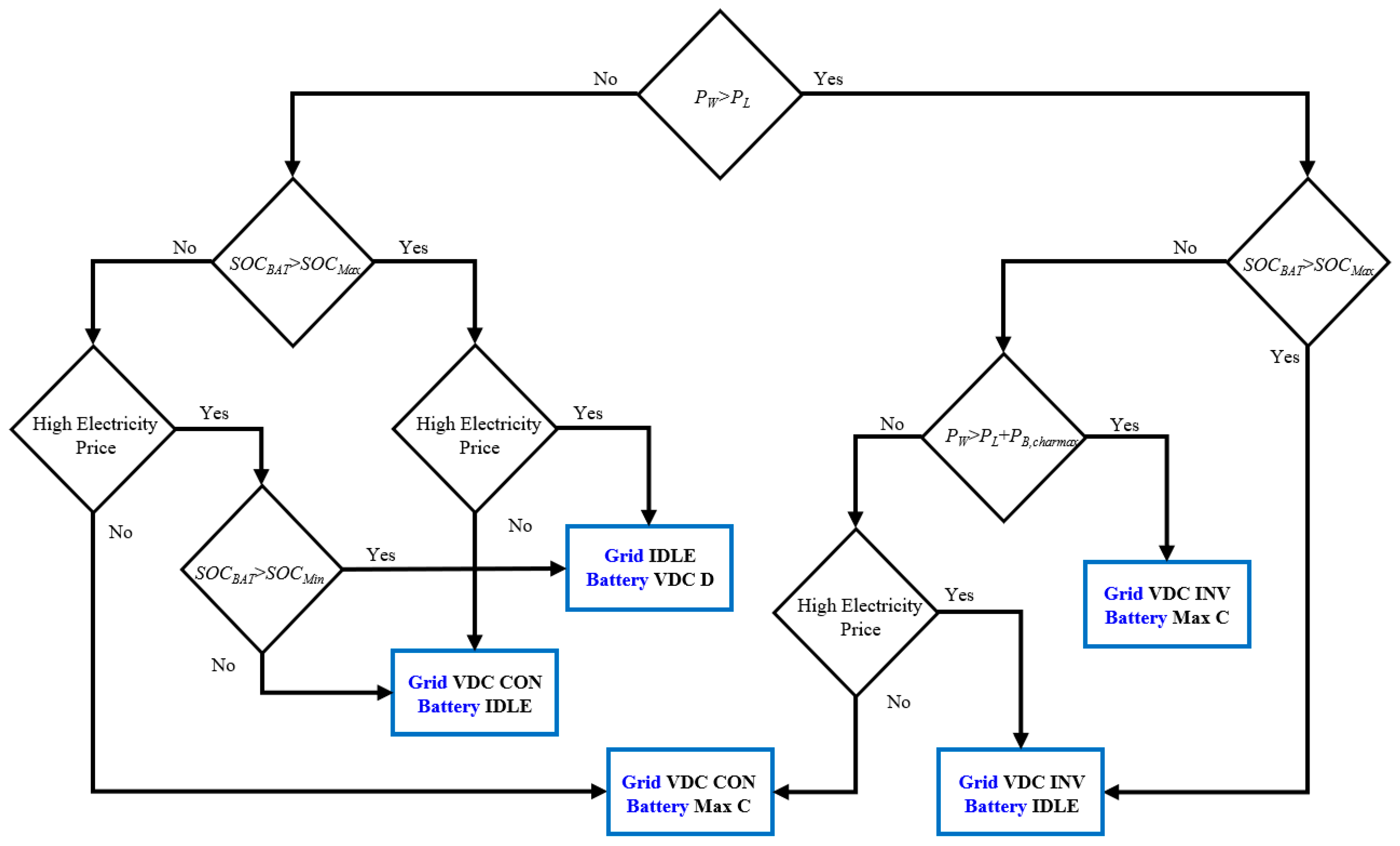
In
Figure 3, a total of five operating modes (denoted by rectangular boxes) compose the power flow control strategy of the DCMG with grid connections when EV departs. In this case, the battery SOC level,
PW, and
PL are considered as dominant factors to select the operating modes. Several operating modes for the DCMG power flow are explained as follows:
As the first example, when the wind power generation PW is higher than PL, and the battery SOC is higher than the maximum SOC level (SOCMax), the grid agent operates in the VDC INV mode to control the DC-link voltage by absorbing the surplus power from the wind power agent. The battery agent operates in the IDLE mode.
As the second example of selecting the operating mode, when the wind power generation
PW is not enough to supply the load power
PL, and the battery SOC is between the minimum SOC level (
SOCMin) and the maximum SOC (
SOCMax) during the high electricity price conditions, the battery agent controls the DC-link voltage by operating in the VDC D mode, and the grid agent operates in the IDLE mode. On the other hand, if the electricity price is in normal condition, the battery agent operates in the Max C mode. The grid agent supplies the necessary power to keep the power balance by operating in the VDC CON mode. The remaining three operating modes of DCMG power flow in
Figure 3 can be explained similarly.
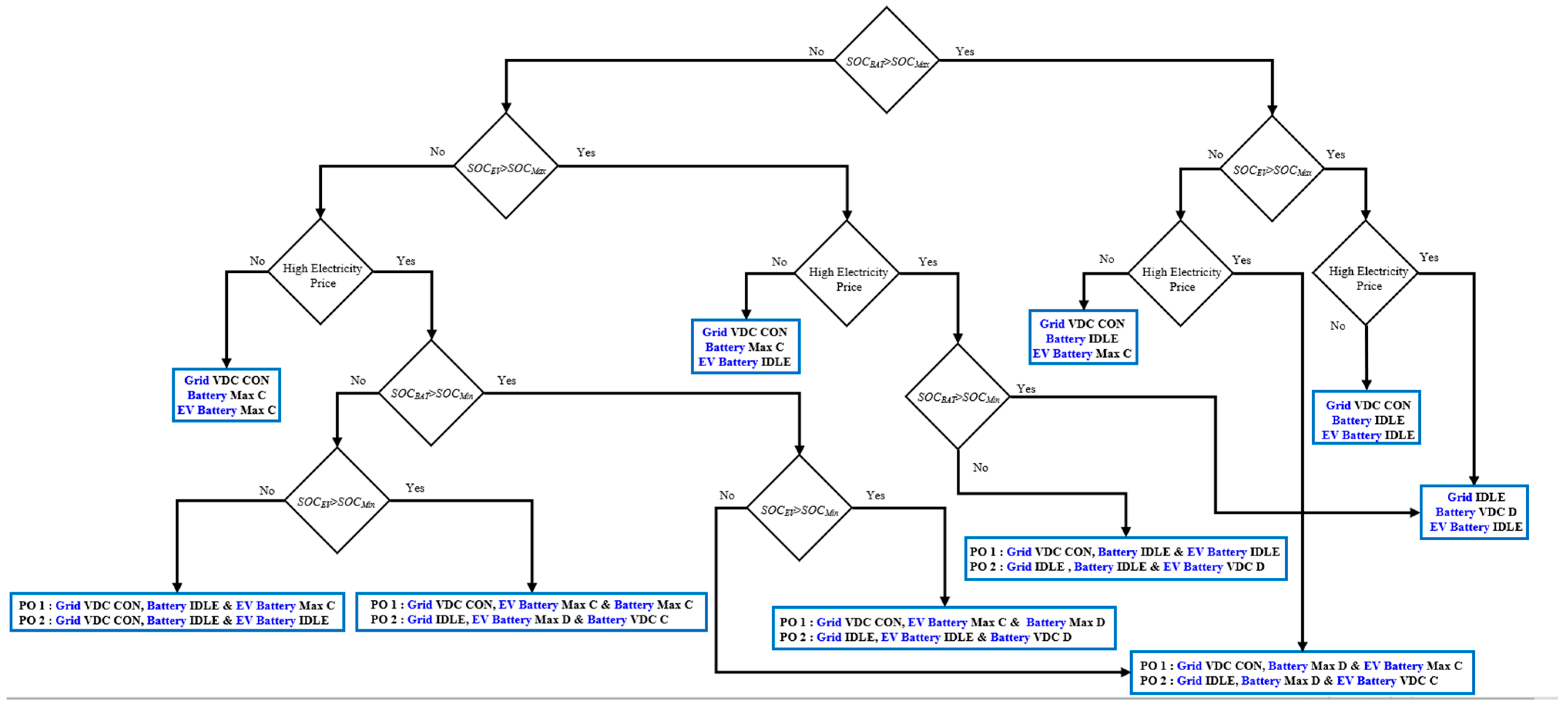
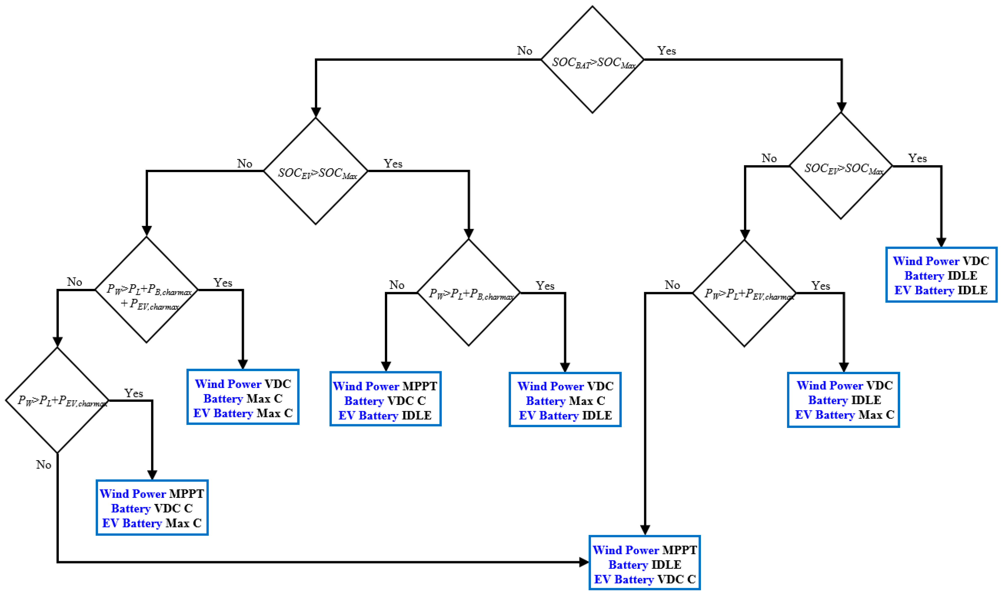
When the EV is connected into the DCMG, the SOC level of the EV battery is also considered to select the best operating modes for the DCMG as shown in
Figure 4 and
Figure 5. The power flow control schemes in these figures are designed in order to fulfill different prime objectives under the constraint of uncertainty in electricity price conditions.
Table 2 shows the prime objectives (POs) of the EV-connected DCMG considered in this study. The first prime objective is to maintain the EV battery level as maximum as possible. The other prime objective is to achieve a minimum utility cost. Depending on the selected prime objective, the power agents of the DCMG should operate differently. Obviously, in some conditions of
Figure 4 and
Figure 5, the operating modes for the power agents are determined regardless of the selection of prime objective. According to the selected prime objective, the operating mode change of each power agent is clearly represented in
Figure 4 and
Figure 5 by expressing the agent operation after PO 1 and PO 2. Several operating modes in
Figure 4 are described as follows:
In the case that the SOC levels of the EV and battery agents are in the normal region (between SOCMin and SOCMax) under high electricity price conditions, the operation mode of the DCMG is decided based on the selected prime objective. If PO 1 is selected as the prime objective of the DCMG to benefit the EV owner, the EV agent operates in the Max C mode to maximally charge the EV battery with the allowable power from the grid. In this case, the grid regulates the DC-link voltage through the VDC CON mode. On the contrary, if PO 2 is selected to reduce the electricity cost, the operations of both the grid and EV agents are changed into IDLE mode, and the battery agent operating in VDC D mode takes the role of maintaining VDC at the nominal value. In both cases, the wind power agent works in the MPPT mode, as mentioned before.
In the case that the SOC levels of EV and battery agents are in the critical condition (less than SOCMin) under the high electricity price conditions, the grid agent controls the DC-link voltage in the VDC CON mode, and the battery is put to IDLE mode. The behavior of the EV agent is chosen based on the selected prime objective function of the DCMG. If PO 1 is selected, the operating mode of the EV agent should be in Max C to charge the EV battery as soon as possible. On the other hand, if PO 2 is selected, the IDLE mode should be used for the EV agent to minimize the consumer electricity price.
The selection of prime objectives also affects the two operating modes in
Figure 5. The first case occurs when the SOC levels of EV and battery agents are either in the normal or critical region; in addition, the wind power generation
PW cannot supply the demand load
PL, and the maximum EV charging power
PEV,charmax is under high electricity price conditions. In this case, the battery agent operates in IDLE mode regardless of the selection of prime objective. However, the prime objective selection affects the operating modes of the other agents. If PO 1 is selected, the grid agent operates in the IDLE mode. Meanwhile, the EV agent operates in the VDC C mode to charge the EV battery by regulating the DC-link voltage. If PO 2 is selected, the EV agent operation is changed into the IDLE mode. The grid agent operation is changed into the VDC INV mode to inject the surplus power from the wind power agent into the utility to minimize the utility cost.
The operating modes of each power agent are also influenced by selecting the prime objective in the case of EV SOC level, eventually reaching the threshold SOCMax, while the SOC level of the battery agent is still in the normal region under high electricity price conditions. In this condition, the EV agent operates in IDLE mode regardless of the selection of prime objective because the EV SOC is already in full-charge condition. If PO 1 is selected, the battery agent takes the responsibility to control the DC-link voltage by operating the VDC C mode, while the grid agent operates in IDLE mode. If PO 2 is selected, the battery agent operates in the Max D mode to maximize the profit by injecting the energy into the main grid to supply more power into the DCMG. The grid agent operates in the VDC INV mode.
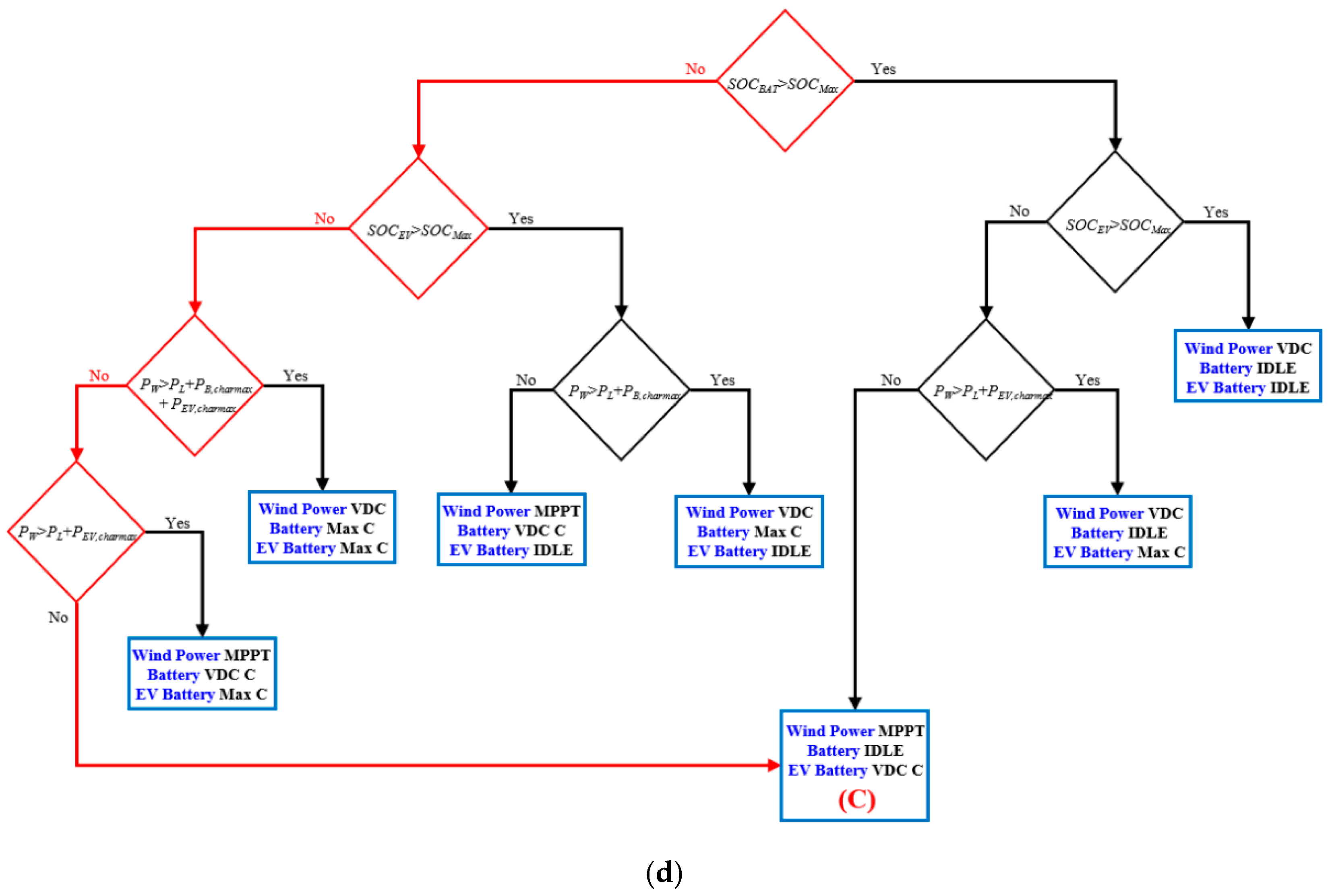
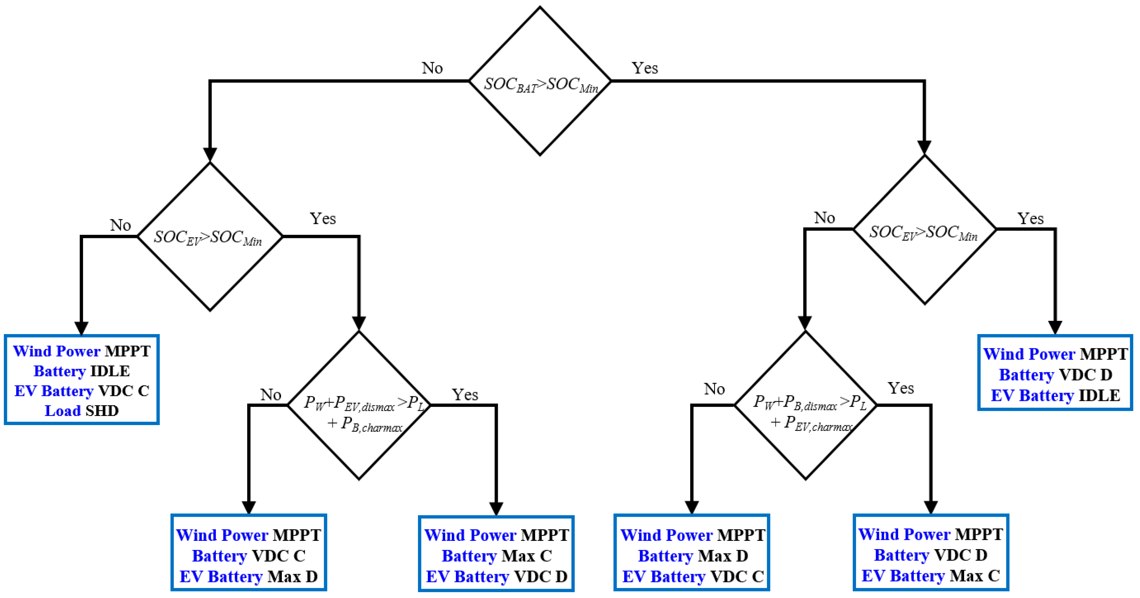
3.2. Power Flow Control of Islanded DCMG with EV Connection
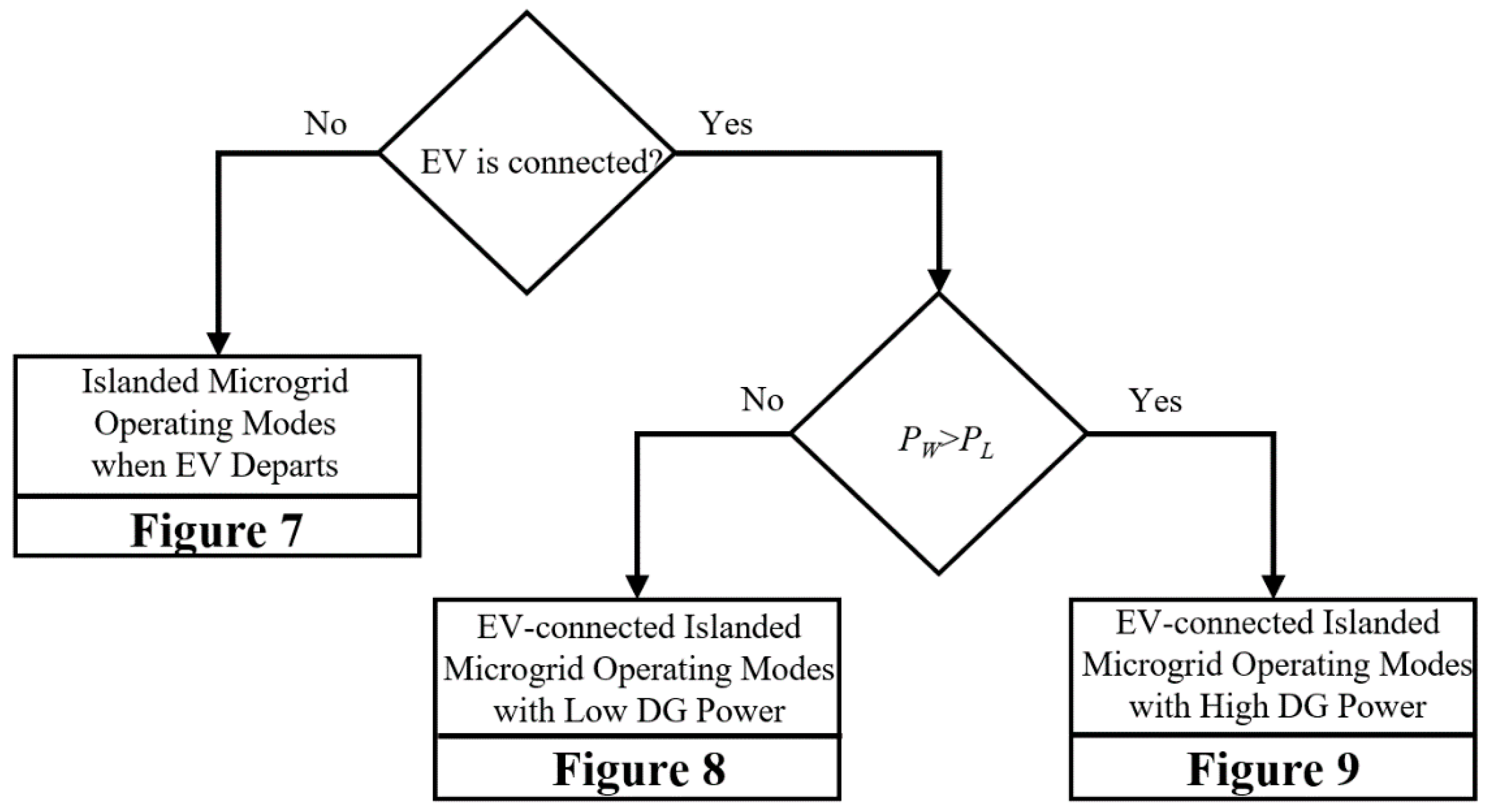
Figure 6 presents the power flow control strategy of the islanded DCMG with EV connections. Similar to the grid-connected DCMG case, the power flow control in
Figure 6 is classified into three main groups according to the existence of EV and the power generation of the DG.
Figure 7 shows the power flow control of the islanded DCMG when the EV departs from the DCMG.
Figure 8 and
Figure 9 show the power flow control schemes of the EV-connected islanded DCMG with low DG power and high DG power, respectively. Since the grid agent is absent in the islanded DCMG case, maintaining the EV battery in a maximum state as much as possible is considered as the only prime objective. As a result, each power agent maintains the same operating mode according to the prime objective.
In the islanded DCMG, the critical condition in which the power balance of the DCMG is liable to collapse may occur when the wind power generation
PW is less than the demand load
PL and the remaining agents cannot supply power to the DCMG due to the low SOC levels of the battery and EV agents. In this condition, the load agent activates the SHD mode to reduce the demanded load power until the power balance is ensured. Since the wind power agent operates in the MPPT mode, if there is a small surplus power in the DCMG after a load shedding event, it can be absorbed by the battery or the EV agent to restore the power balance in which battery and EV agents operate in the VDC C mode as shown in
Figure 7 and
Figure 8, respectively. When the DCMG system is changed into the grid-connected mode due to the grid recovery, the load agent triggers the RECON operating mode to reconnect the shedded load. The load reconnection is also achieved when the SOC levels of the battery or EV agent are recovered to a sufficient value in the islanded DCMG mode.
The absence of the grid agent also affects the operation of the DG system such as the wind power agent. In the grid-connected DCMG case, the DCMG can inject surplus power to the main grid even if the generated power of the wind power agent exceeds the demanded load power. As a result, as stated in
Section 3.1, the wind power agent is always operated in the MPPT mode in the grid-connected case to draw the maximum power.
On the contrary, in the islanded DCMG case, surplus power cannot be injected into the grid. In addition, the power absorption of battery and EV agents may be limited under certain conditions. When these energy storage devices have a higher SOC level than
SOCMax, the battery or EV agent cannot receive additional power. This condition also occurs when the power from the wind power agent exceeds the maximum absorbable power in the DCMG either by the load or energy storage devices. As shown in
Figure 7, when
PW is greater than
PL, and the battery agent SOC is in full charge (greater than
SOCMax) condition, the wind power agent should reduce the power generation. This condition can also be observed in
Figure 9, where
PW is greater than
PL, and the SOC levels of the EV and battery agents are in full charge condition. Instead of operating in the MPPT mode, the wind power agent uses the VDC mode to reduce the power generation by regulating the DC-link voltage. In this case, the energy storage devices such as the EV and battery operate in IDLE mode.
Integrating EV agents into the DCMG system significantly increases the flexibility in power system operation. In a low DG power case, as shown in
Figure 8, the battery can supply power for the EV agent to fulfill the prime objective when the battery SOC is more than
SOCMin, and the EV SOC is lower than
SOCMin. The modes of the EV and battery are chosen in relation to the total wind power generation
PW, the maximum discharging power of the battery
PB,dismax, the total load demand
PL, and the maximum charging power of the EV
PEV,charmax. Suppose the total power injection into the DCMG surpasses the total power absorption. In that case, the EV agent operates in the Max C mode, and the battery agent operates in the VDC D mode. On the contrary, if the total power injection into the DCMG from the wind power and battery cannot support the load and EV charging, the battery agent operates in the Max D mode, and the EV agent operates in the VDC C mode.
The EV agent introduces significant flexibility to improve the power system stability in the islanded DCMG by helping the battery agent avoid the critical condition if the EV SOC level is sufficient. Similar to the previous case, when the total injecting power into the DCMG from the wind power and EV exceeds the total absorbing power by the load and battery charging, the battery agent operates in the Max C mode, and the EV agent controls the DC-link voltage in the VDC D mode. On the contrary, if the total injecting power into the DCMG is less than the total absorbing power, the EV agent supplies the DCMG by operating in the Max D mode, and the battery agent operates in the VDC C mode to maintain the DC-link voltage at the nominal value.
4. Simulation Results
To validate the usefulness of the power flow control scheme for a DCMG system with EV and grid connections, the simulation has been conducted using the PSIM software tool. The performance and reliability of the proposed DCMG control scheme are tested in the presence of several uncertainties such as the generated power, EV connection and disconnection times, initial SOC level of the EV battery, grid availability, and electricity price conditions. The DCMG system parameters are listed in
Table 3, in which the maximum and minimum SOC values of the battery and EV agents are determined as 90% and 20%, respectively [
34]. Simulations are conducted for five cases: low DG power, high DG power, prime objective change in low DG power, prime objective change in high DG power, and islanded DCMG with EV connections.
In these simulation tests, all the power agents start the control at
t = 0.1 s. The currents of the grid agent, battery agent, EV agent, wind power agent, and load agent are denoted as
IG,
IB,
IEV,
IW, and
IL, respectively. The powers of the wind power and load agents are represented as
PW and
PL. The reference direction of currents and powers follows
Figure 1a. The positive DC current indicates that the current flows from the DC-link into each power agent, and the negative DC current indicates that the current flows from the power agent into the DC-link.
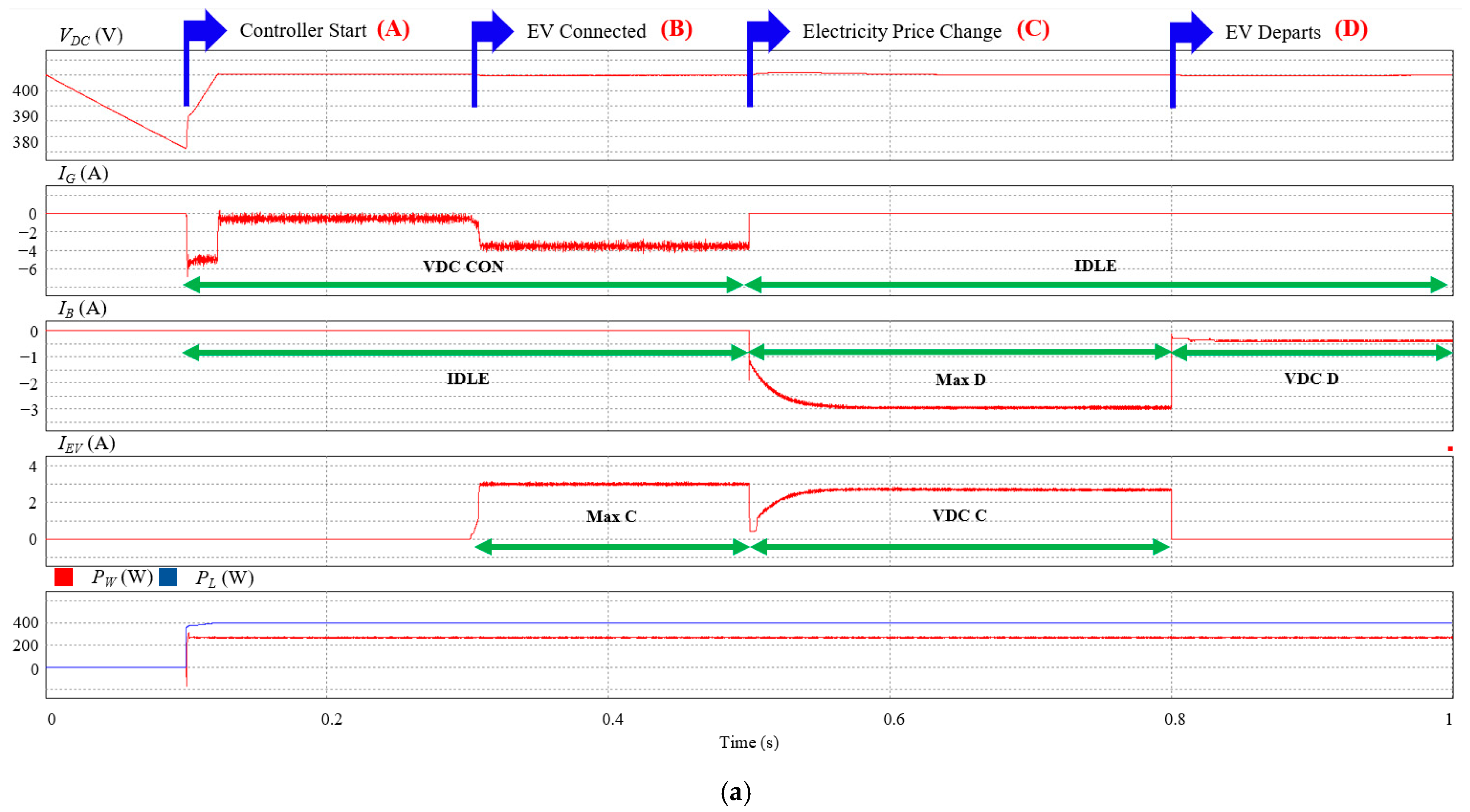
4.1. Case of Low DG Power
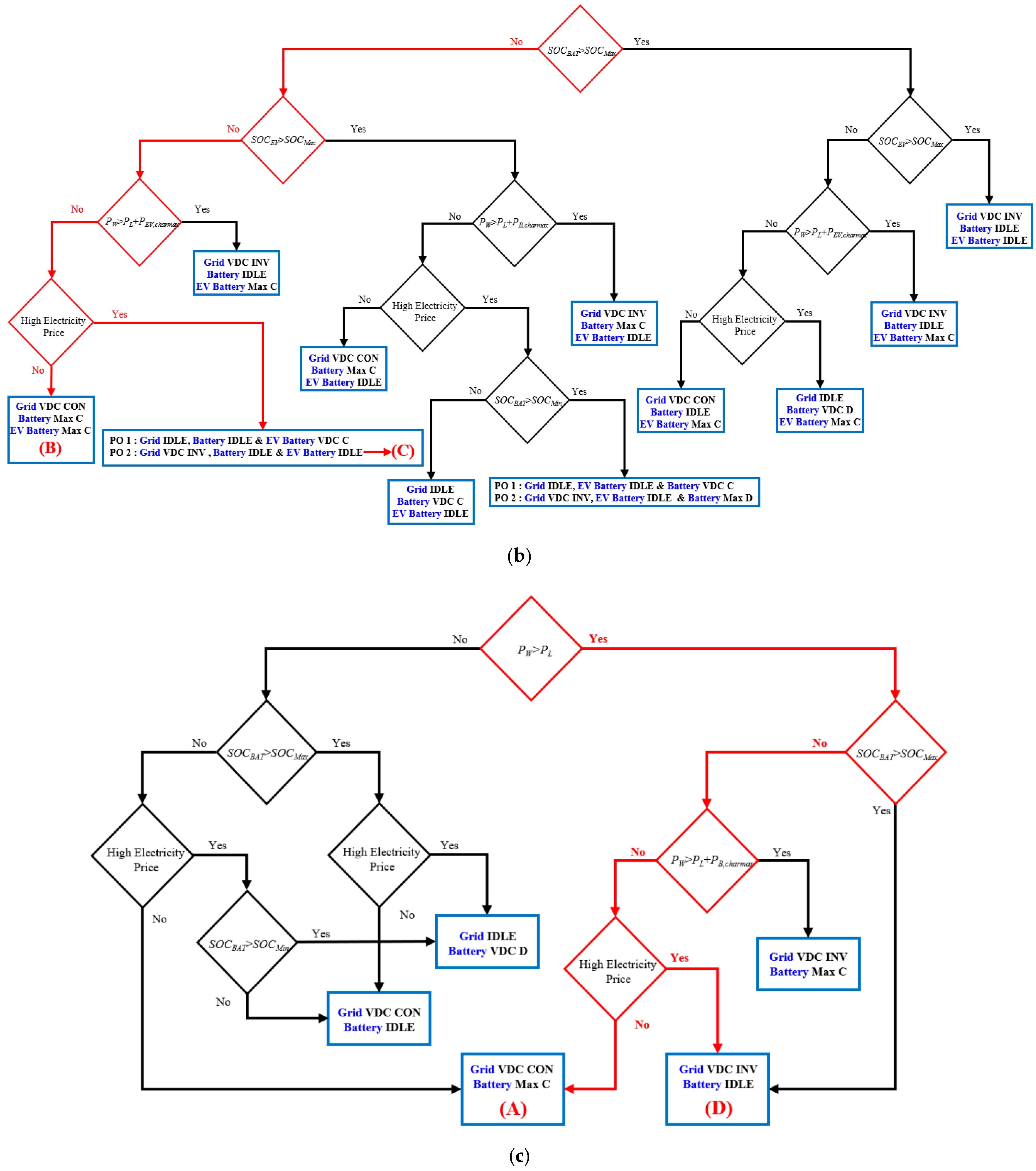
Figure 10a depicts simulation results for the power flow control scheme of the DCMG with EV and grid connections for the low DG power case. In this test, the EV is connected to the DCMG from
t = 0.3 s to
t = 0.8 s, and the electricity price increases at
t = 0.5 s. To clearly show the determination process of the operating modes,
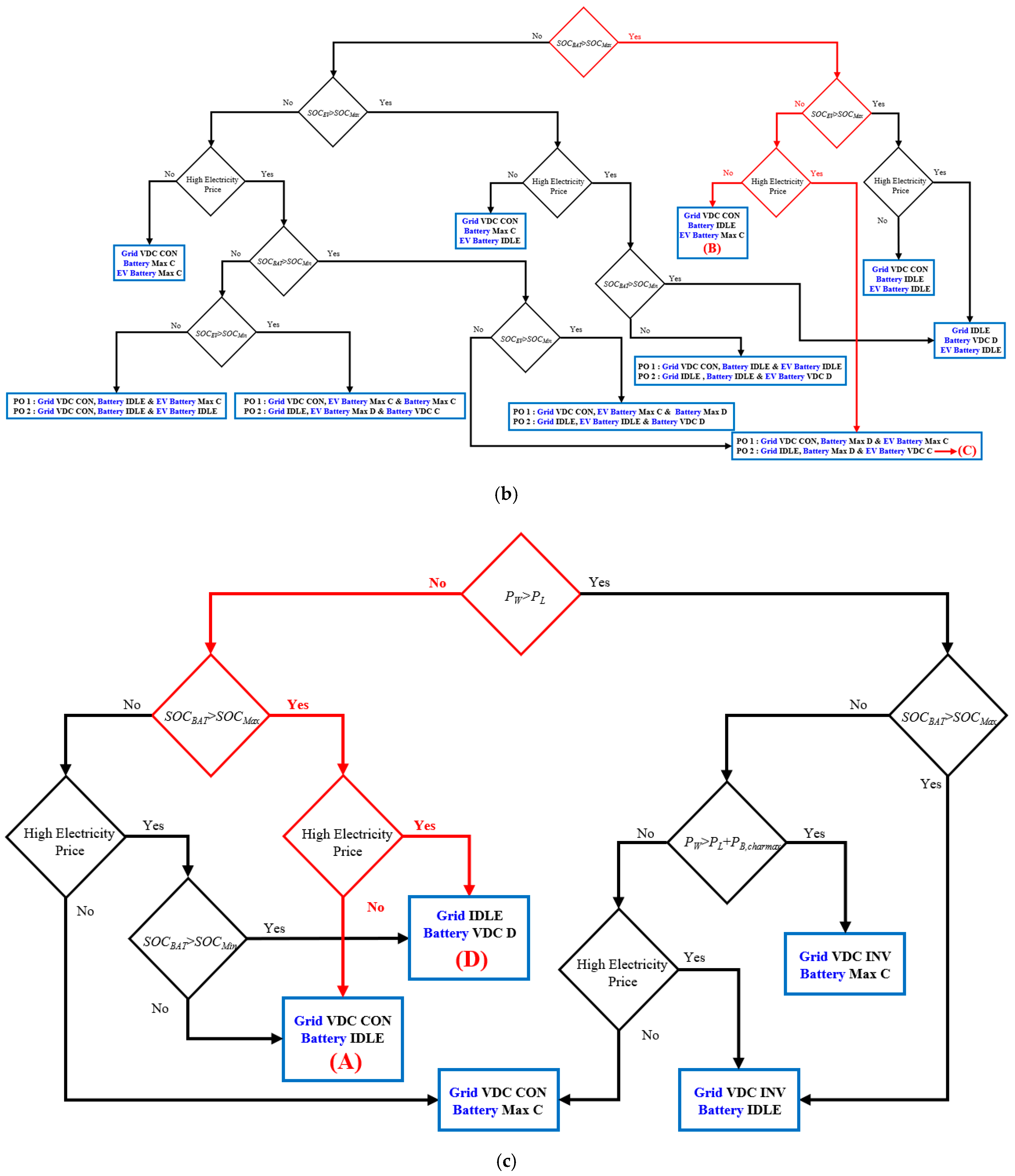
Figure 10b,c represent the selection of particular operating modes of all power agents in the DCMG with red lines by using the presented power flow control in
Figure 3 and
Figure 4.
Initially, the EV agent is not connected to the DCMG system under the battery full charge condition and the normal electricity price conditions. Since the power from wind power agent
PW is less than the load power
PL, the DCMG system starts the operation with the operating mode (A) in
Figure 10c, in which the grid agent regulates the DC-link voltage in the VDC CON mode, the battery agent operates in the IDLE mode, and the wind power agent operates in the MPPT mode. This operation continues until the EV agent is connected to the DCMG system at
t = 0.3 s.
At
t = 0.3 s, the EV is connected to the DCMG with a normal EV SOC level. Then, the DCMG operation is changed into mode (B) in
Figure 10b. Since the electricity price is still in normal condition during this period, the wind power agent, battery agent, and grid agent keep the same modes as the MPPT, IDLE, and VDC CON modes, respectively. The connected EV agent operates in the Max C mode to increase the SOC level rapidly by charging with the maximum allowable power, which attracts more power from the grid agent.
When the electricity price is increased at
t = 0.5 s, the DCMG system starts a new operation according to the prime objective. If the prime objective is selected as PO 2, which achieves the minimum utility cost, the DCMG operation is determined as the operating mode (C) in
Figure 10b. As a result, the grid is put to the IDLE mode to ensure no more power is injected into the DCMG from the grid. Instead, to supply the deficient power into the DCMG, the battery agent operates in the Max D mode. The EV agent takes the responsibility to maintain the DC-link voltage by operating in the VDC C mode.
Finally, when the EV departs from the DCMG at
t = 0.8 s, the DCMG operation is set to the operation mode (D), as shown in
Figure 10c. Due to high electricity price conditions, the grid agent still operates in IDLE mode. As a result of the departure of the EV agent, which controls the DC-link voltage, the role of regulating the DC-link voltage is transferred to the battery agent with the VDC D mode.
Even though events such as “EV connections”, “the electricity price change”, and “EV departure” do not occur in the one-second interval,
Figure 10 uses this time interval for the purpose of shortening the software running time and also proving that the power flow control algorithm works stably and robustly even under such varying conditions. The simulation result of
Figure 10 can be understood more practically by considering the time axis scale of 1 s as 1 h.
4.2. Case of High DG Power
Figure 11a shows simulation results for the power flow control scheme of the DCMG with EV and grid connections for a high DG power case. Similar to
Figure 10, the EV is connected to the DCMG from
t = 0.3 s to
t = 0.8 s, and the electricity price increases at
t = 0.5 s. The determination process of the operating modes of all the power agents is also clearly shown in
Figure 11b,c with red lines by using
Figure 3 and
Figure 5.
Similar to the previous case, when the DCMG starts the operation at
t = 0.1 s, the EV is disconnected. Initially, both SOC levels of the EV and battery agents are in the normal region, and the power from wind power agent
PW is higher than the required load power
PL. However,
PW is less than the sum of
PL and
PB,charmax. As a result, the DCMG operation is determined as the mode (A) in
Figure 11c, in which the wind power agent operates in the MPPT mode, the battery is charged with the maximum allowable current in the Max C mode, and the grid agent supplies inadequate power by operating in the VDC CON mode.
As soon as the EV is connected to the DCMG at
t = 0.3 s, the DCMG operation is switched into mode (B) in
Figure 11b. Since the electricity price is still in normal condition during this period, the wind power agent, battery agent, and grid agent maintain operations as the MPPT mode, Max C mode, and VDC CON mode, respectively. In addition, the EV agent starts charging the EV battery in the Max C mode.
As the electricity price is increased at
t = 0.5 s, the DCMG operation is set to mode (C) in
Figure 11b. In this mode, to achieve PO 2, which minimizes the electricity price, the EV and battery agents change the operation into the IDLE mode. On the other hand, the grid agent operation is changed to the VDC INV mode to inject the power into the grid by controlling the DC-link voltage.
Finally, when the EV is disconnected from the DCMG at
t = 0.8 s, the DCMG changes its operation into the mode (D) in
Figure 11c, where the grid agent, battery agent, and wind power agent maintain the previous operating modes.
These simulation results confirm that the overall performance of the DCMG power flow control is not affected by the EV’s sudden connection and disconnection, uncertain EV SOC level at the initial time, the variation of electricity price conditions, and the wind power generation PW.
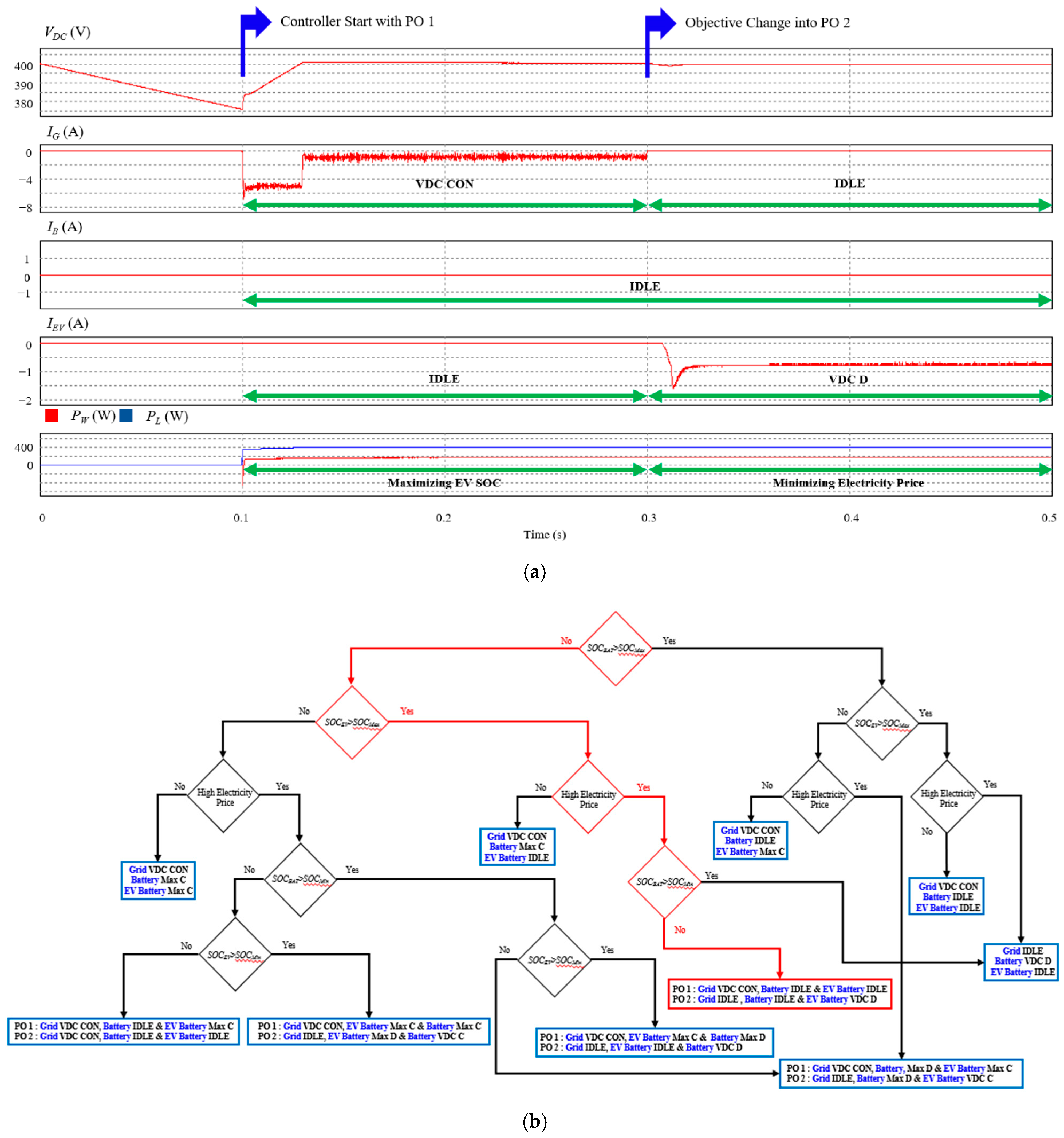
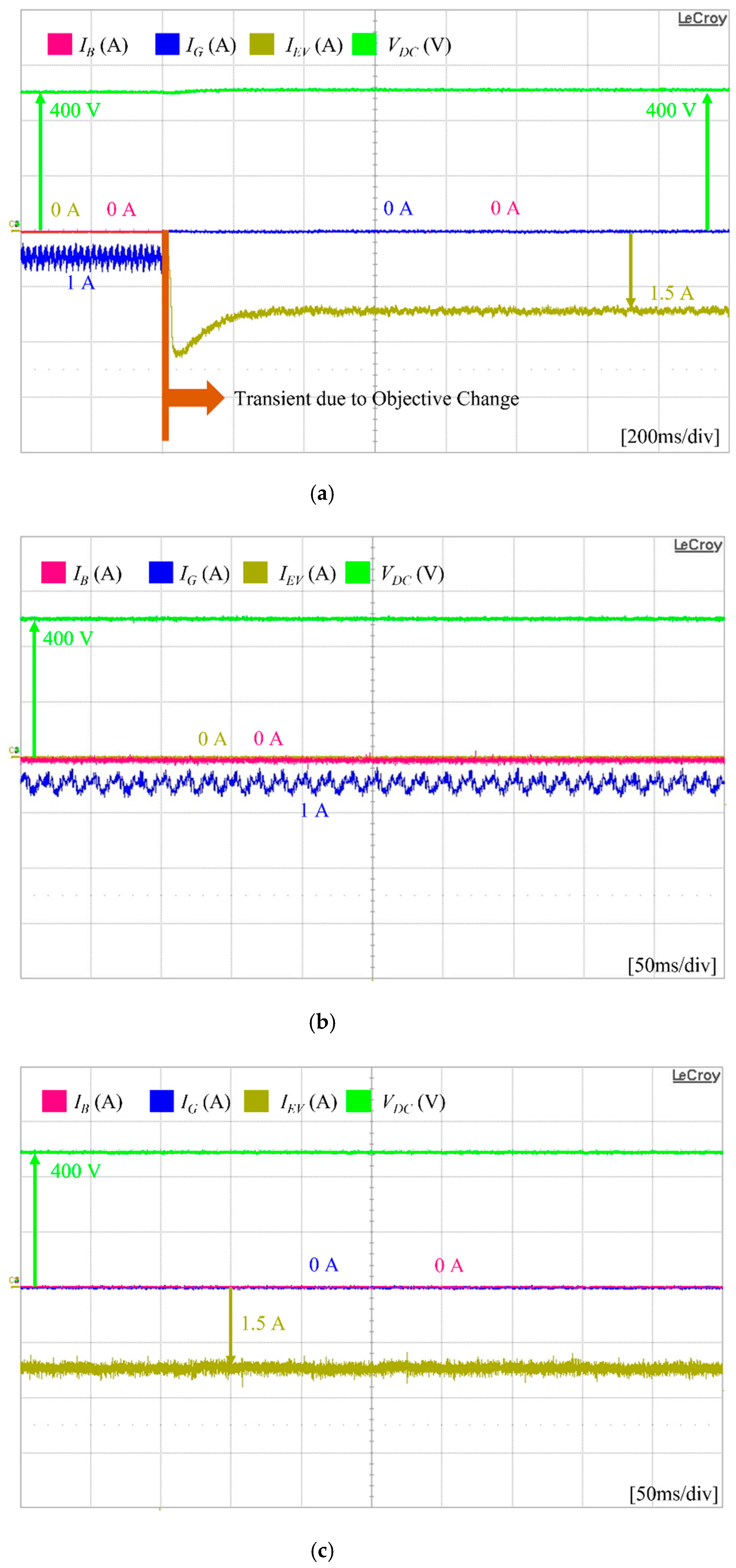
4.3. Case of Prime Objective Change with Low DG Power
Figure 12a presents the simulation results of the DCMG power flow control with EV and grid connections under the prime objective change at
t = 0.3 s with low DG power and high electricity price conditions, and
Figure 12b shows the operating mode selection process of the DCMG. All the power agents start operation at
t = 0.1 s. In this test, it is assumed that
PW is less than
PL, the SOC level of the EV agent is in full charge condition, and the battery SOC level is less than
SOCMin. Additionally, the initial prime objective is selected as PO 1. As a result, the operations of the battery and EV agents are in IDLE mode, while the grid agent works with the VDC CON mode to control the DC-link voltage by injecting the power into the microgrid as shown in
Figure 12a,b.
However, as soon as the prime objective is changed from PO 1 into PO 2 at
t = 0.3 s, the DCMG power flow control changes the operating modes of the power agents as specified in
Figure 12b. The prime objective of PO 2 is to minimize the utility cost as shown in
Table 2. To achieve PO 2, the grid agent operation is changed into IDLE mode to prevent the main grid from supplying more power into the DCMG. The battery agent maintains its operation in IDLE mode. The EV agent operation is shifted to the VDC D mode in order to regulate the DC-link voltage, and the wind power agent operates in the MPPT mode.
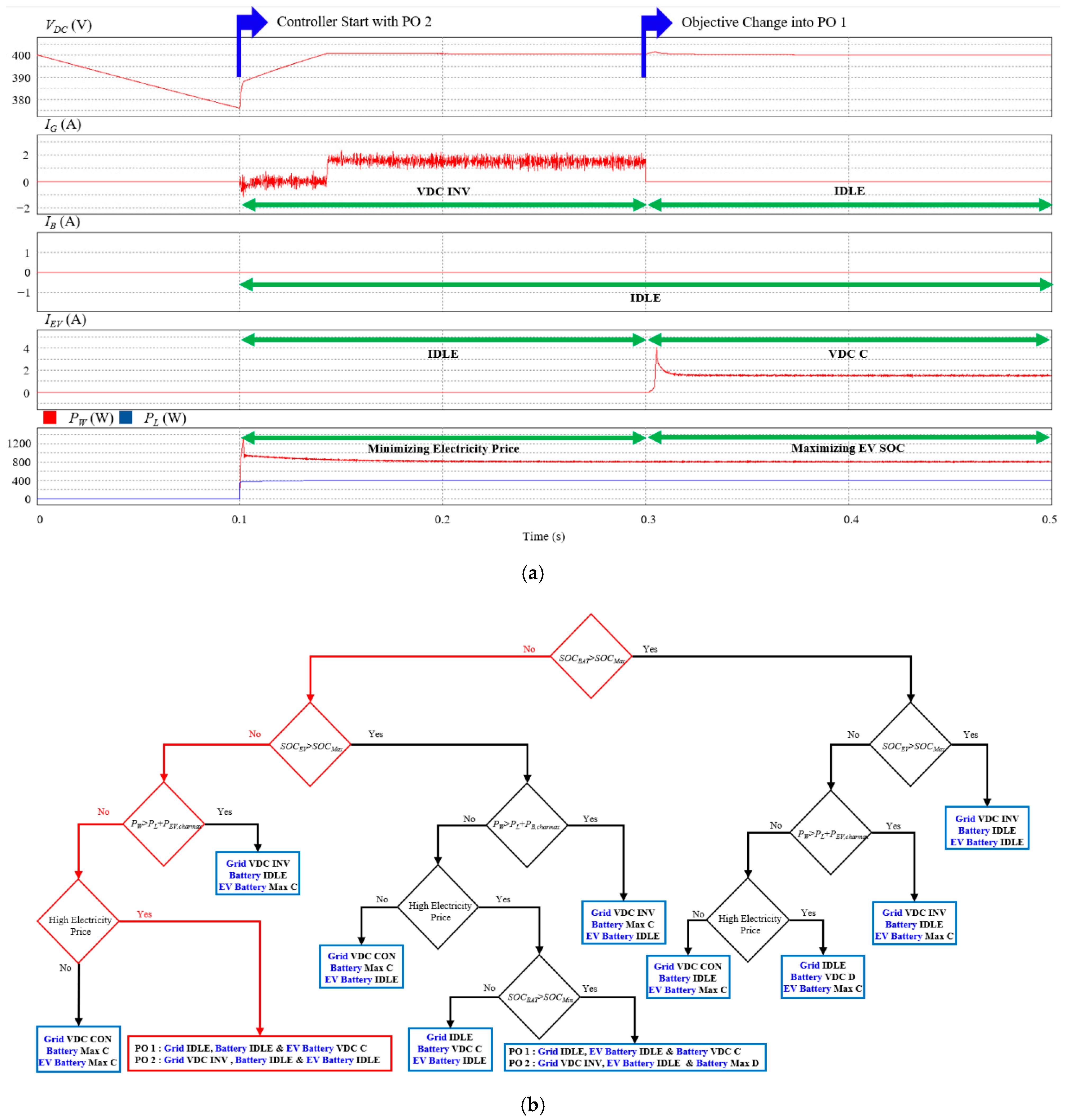
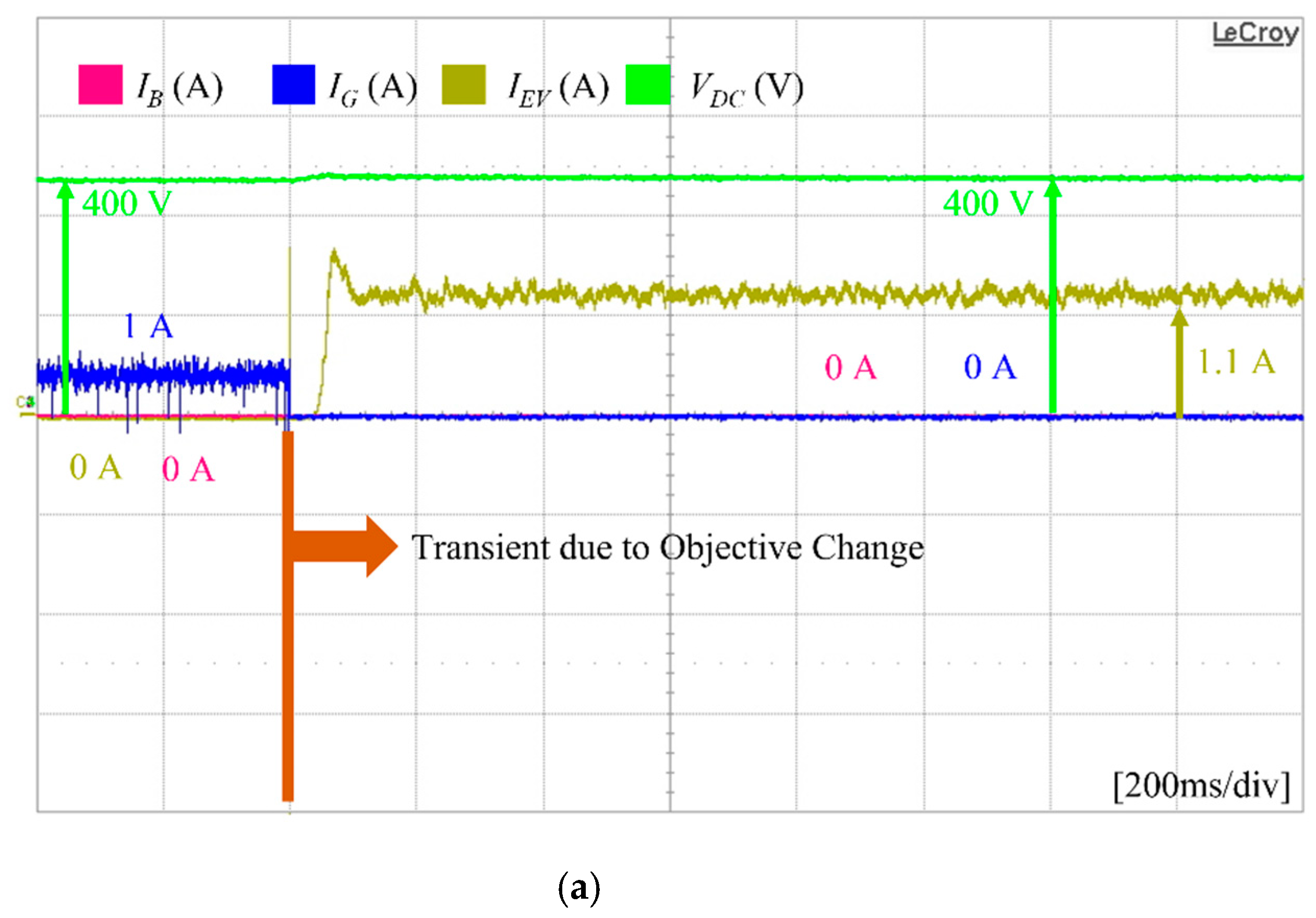
4.4. Case of Prime Objective Change with High DG Power
Figure 13a shows simulation results of the DCMG power flow control with EV and grid connections under prime objective change at
t = 0.3 s with high DG power, and
Figure 13b shows the operating mode selection process of the DCMG. Similar to the test conditions in
Figure 12, the SOC levels of both the battery and EV agents are in the normal region, and all power agents start the operation at
t = 0.1 s. However, this test considers the case that
PW is greater than
PL. When PO 2 is selected as the prime objective of DCMG initially, the EV and battery agents operate in IDLE mode, and the grid agent operates in VDC INV mode, as shown in
Figure 13a,b.
As the prime objective is changed from PO 2 into PO 1 at t = 0.3 s, the grid agent shifts its operation into the IDLE mode to stop absorbing the power from the DCMG system. Instead, the surplus power in the DCMG is absorbed by the EV agent with the VDC C mode.
In spite of a sudden transition of the DCMG prime objective, the simulation results prove that all the power agents operate stably within the DCMG system without an extreme transient behavior, which verifies the robustness of the proposed scheme.
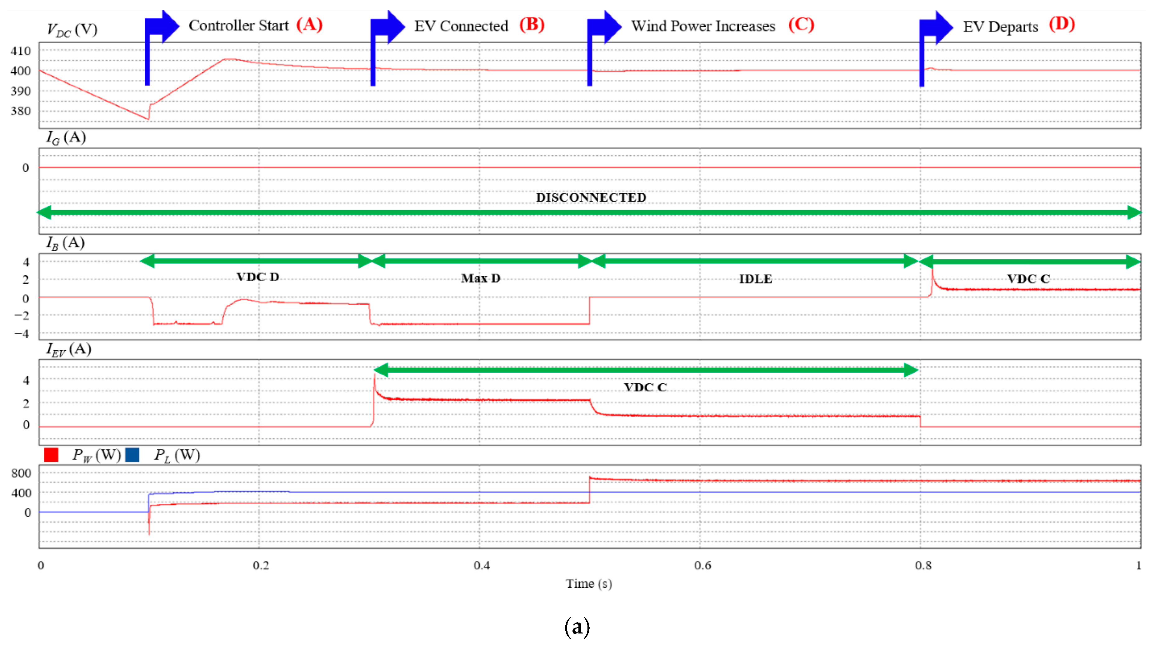
4.5. Case of Islanded DCMG with EV Connection
Figure 14a shows the simulation results of the islanded DCMG power flow control with EV connections.
Figure 14b–d represents the operating mode selection in the islanded DCMG under the EV disconnection, EV connections with low DG power, and EV connections with high DG power, respectively. In this islanded DCMG test, similar to the grid-connected case, the EV is connected at
t = 0.3 s and disconnected at
t = 0.8 s with the SOC level less than
SOCMin. At first, the wind power generation
PW cannot supply the required load power
PL until
t = 0.5 s. After that,
PW is increased to a greater value than
PL. Additionally, the SOC level of the battery agent is in the normal region. All power agents start operation at
t = 0.1 s.
Initially, because the wind power generation is not sufficient to supply the load demand, the DCMG starts the operation with mode (A) in
Figure 14b, in which the wind power agent operates in the MPPT mode, and the battery agent supplies the deficient power to the DCMG by operating in the VDC D mode.
Once the EV is connected to the DCMG at
t = 0.3 s, the DCMG operation is changed into mode (B) in
Figure 14c since the EV SOC is less than
SOCMin. In this operating mode, the wind power agent remains in the MPPT mode, the battery agent supplies the DCMG with the maximum allowable discharging power (
PB,dismax) by changing its operation into the Max D mode, and the EV agent starts the charging operation with the VDC C mode by regulating the DC-link voltage.
As the wind power
PW is higher than
PL at
t = 0.5 s, the DCMG changes its operation into mode (C) in
Figure 14d. In this case, due to the power increment in wind power generation, the wind power agent can support the load demand and EV charging. Consequently, the battery agent operation is changed into IDLE mode, while the wind power agent and the EV agent maintain their previous operations.
When the EV departs from the DCMG at
t = 0.08 s, the DCMG operates with the mode (D) in
Figure 14b. The wind power agent is still in MPPT mode. The battery agent absorbs the surplus power with the VDC C mode, in which the battery is charged by controlling the DC-link voltage.
These simulation results also prove that all power agents of the DCMG system work reliably in the islanded case even under the uncertainties of the EV connection and disconnection times, EV initial SOC value, and wind power generation.
6. Conclusions
This paper has presented a centralized power flow control scheme of EV-connected DCMG to satisfy multi-objective problems under several constraints. Considering a wind power agent, battery agent, EV agent, load agent, and grid agent as DCMG components, a reliable and optimized DCMG system that is capable of satisfying the selected prime objective function is constructed. For this aim, two prime objective functions are presented in this study to provide a benefit to the DCMG system or the EV owners. The power flow control strategy is devised for the grid-connected mode as well as the islanded mode. Moreover, considering the amount of DG power and the existence of EV in DCMG, the power flow control scheme is further subdivided to constitute six power flow control groups. In the proposed scheme, the operating modes of power agents in the DCMG are effectively decided based on the EV connection/disconnection status, initial SOC value of the EV, power generation of the wind power agent, battery SOC level, and grid availability. The electricity price conditions and the DCMG prime objective are also employed to decide the operating modes of the power agent. The main contributions of this study can be summarized as follows:
A power flow control scheme for an EV-connected DCMG is developed. The proposed scheme stably maintains the DC-link voltage at the nominal value without extreme transients even under the uncertainties of DG power, grid availability, electricity price conditions, and EV connections.
By using the proposed scheme, a power flow control strategy that can provide benefits to the DCMG system or the EV owners can be flexibly selected. Depending on the selection of the prime objective function, the DCMG system can be controlled to maximize the EV battery SOC or to minimize the electricity price. Despite the DCMG prime objective change, the proposed scheme ensures a stable and smooth DCMG operation without severe transience.
Since the proposed scheme does not need a complex data-driven optimization algorithm and is devised based on several uncertainty factors, a fast and accurate transition of microgrid operation is achieved as proven in simulation and experimental results. Moreover, it is computationally friendly and easy to implement in the real system.
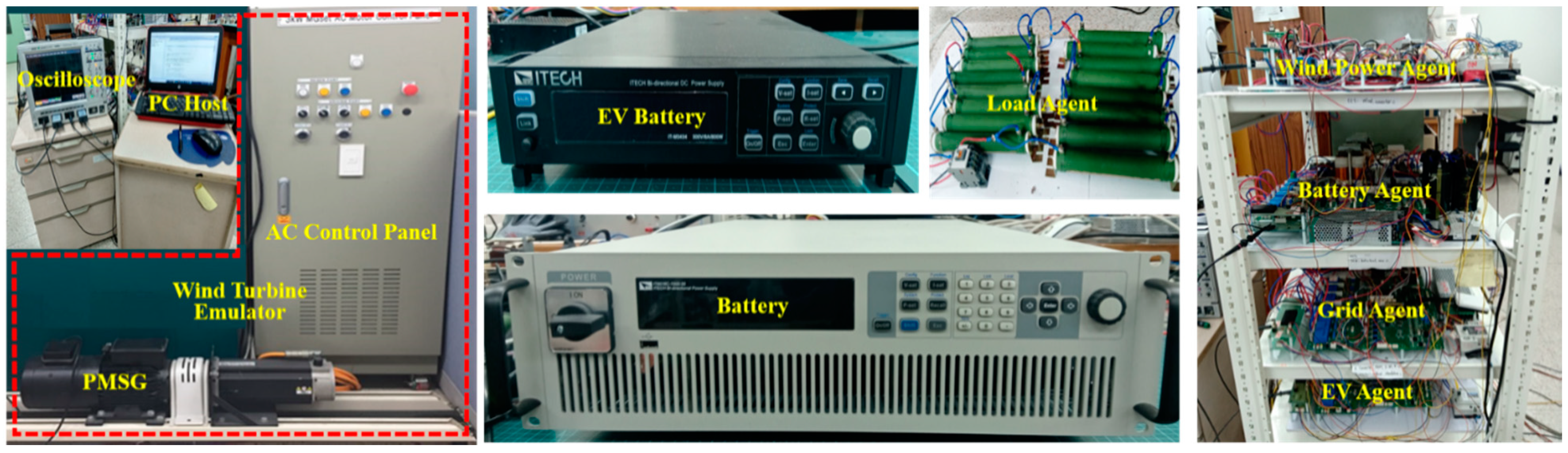
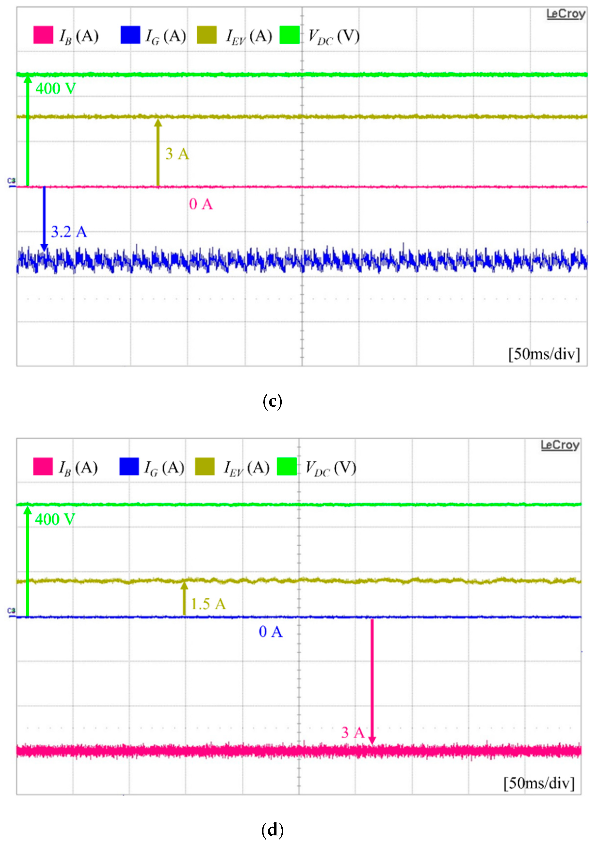
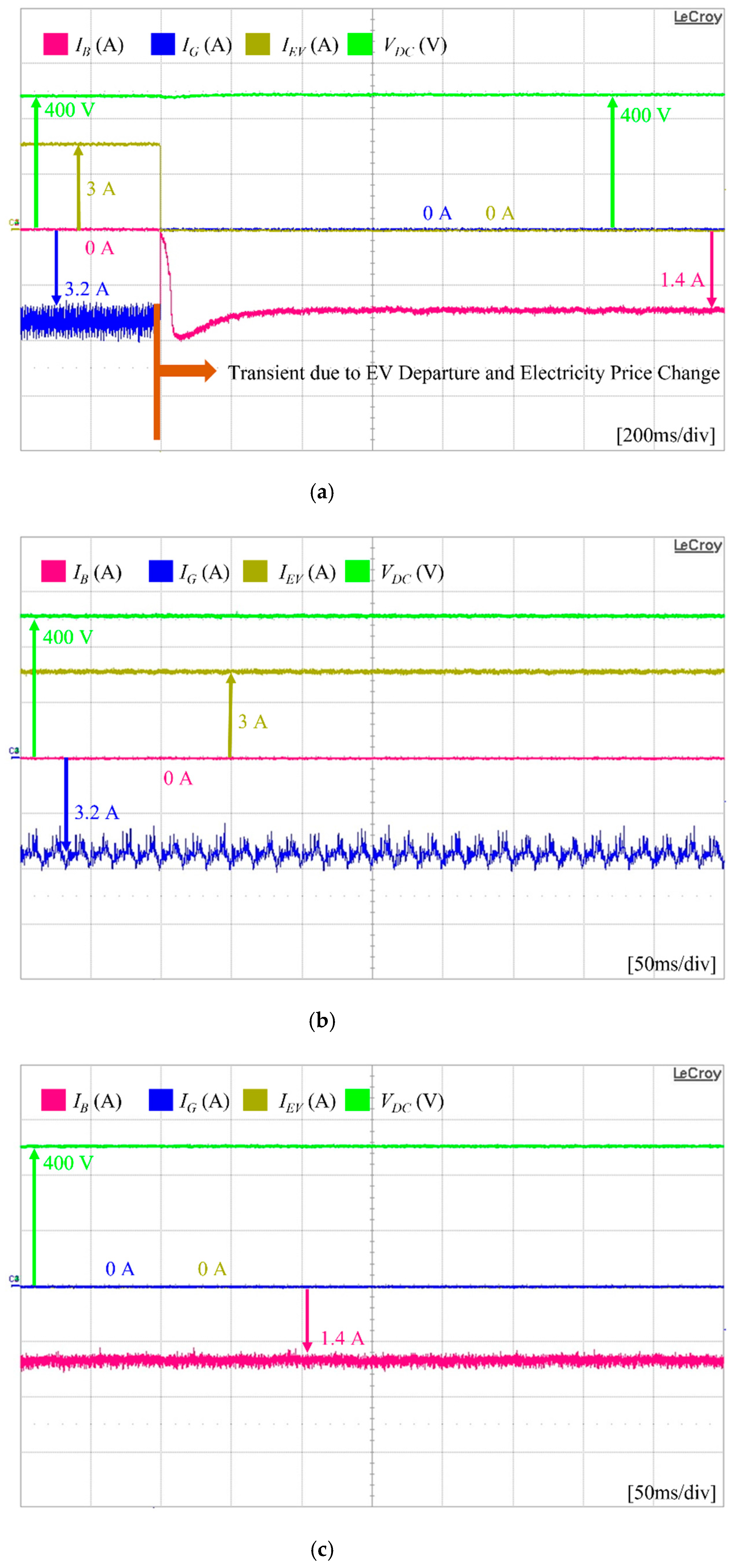
To clarify the practical usefulness of the proposed power flow control scheme for the EV-connected DCMG system, both simulations based on the PSIM software and experiments based on the prototype DCMG testbed have been carried out. In the experimental system, the DCMG consists of a bidirectional AC-to-DC converter to connect the grid source, a unidirectional AC-to-DC converter to connect the wind turbine emulator, and two bidirectional DC-to-DC converters to connect the bidirectional DC sources. Comprehensive simulation and experimental results have proven the usefulness of the proposed power flow control scheme. Several experimental tests confirm that the developed power flow algorithm stably works with satisfactory overall performance even under the uncertainties of power generation from the wind power agent, EV connection and disconnection times, initial SOC levels of the EV battery, and grid availability. In addition, a reliable DC-link voltage regulation performance is also demonstrated by the experiments.


