Article

Corridor-Wise Eco-Friendly Cooperative Ramp Management System for Connected and Automated Vehicles

College of Engineering-Center for Environmental Research and Technology, University of California at Riverside, Riverside, CA 92507, USA
*
Author to whom correspondence should be addressed.
Sustainability 2021, 13(15), 8557; https://doi.org/10.3390/su13158557
Submission received: 22 June 2021 / Revised: 9 July 2021 / Accepted: 12 July 2021 / Published: 31 July 2021

Abstract

:
Safety, mobility, and environmental sustainability are three fundamental issues that our transportation system has been confronting for decades. Intelligent transportation systems (ITS) aim to address these problems by leveraging disruptive technologies, such as connected and automated vehicles (CAVs). The cooperative potential of CAVs enable more efficient maneuvers and operation of a group of vehicles, or even the entire traffic system. In addition, CAVs may couple with other emerging technologies such as electrification to boost overall system performance and to further mitigate the aforementioned issues. In this study, we propose a hierarchical eco-friendly cooperative ramp management system, where macroscopically, a stratified ramp metering algorithm, is deployed to coordinate all of the ramp inflow rates along a corridor according to the real-time traffic condition; microscopically, a model predictive control (MPC)-based algorithm is designed for the detailed speed control of individual CAVs. Using the shared information from CAVs, the proposed ramp management system can smooth traffic flow, improve system mobility, and decrease the energy consumption of the network. Moreover, traffic simulation has been conducted using PTV VISSIM under various congestion levels for vehicles with different powertrain types, i.e., an internal combustion engine and an electric motor. Compared to conventional ramp metering, the proposed ramp management system may improve mobility by 48.6–56.7% and save energy by 24.0–35.1%. Compared to no control scenarios, savings in travel time and energy consumption are in the ranges of 79.4–89.1% and 0.8–2.5%, respectively.

1. Introduction

1.1. Background

Traveling and freight shipping are the basic needs of modern society. As a result, the size of the transportation network is rapidly enlarging, and the number of vehicles is also fast growing. In such a huge system, a mass of issues threatens the health of the system operation and can be condensed into three aspects: safety, mobility, and environmental sustainability. To deal with such a difficult situation, optimizing the current transportation system is imperative, and the rapid development of connected and automated vehicle (CAV) technology is a promising solution. CAV technology enables vehicles to cooperate with the environment using vehicle-to-everything (V2X) communication. By sharing the vehicles’ status and sensing information, the agents of the transportation system may have a better understanding of the whole environment and will be able to make decisions together.
Ramp merging on highways is one of the most commonly seen scenarios in the modern traffic system. For conventional human-driven vehicles, merging at ramps is challenging and can inevitably cause many traffic-related problems [1]. From the safety perspective, the potential conflicts between on-ramp vehicles and mainline vehicles increase the risk of having accidents. From the mobility perspective, the uncontrolled inflow traffic to the highway network results in congestion. From the environmental sustainability perspective, due to the limited vision range (e.g., by obstructions) and uncoordinated merging behaviors, frequent unnecessary acceleration/deceleration maneuvers may occur in the merging area, which leads to excessive energy consumption and pollutant emissions.

1.2. Motivation

The traditional ramp management method is ramp metering, which regulates the inflow rate of the traffic entering the mainline by using traffic signals located at the end of the ramp (see Figure 1 [2]). By controlling the traffic light to change between red and green, only a certain number of vehicles can enter the highway mainline during each predefined interval. The controlled inflow rate is calculated based on traffic conditions. Although ramp metering has been deployed in many real-world scenarios and has proven to be a cost-effective operational strategy to reduce mainline congestion, it has a few major drawbacks:
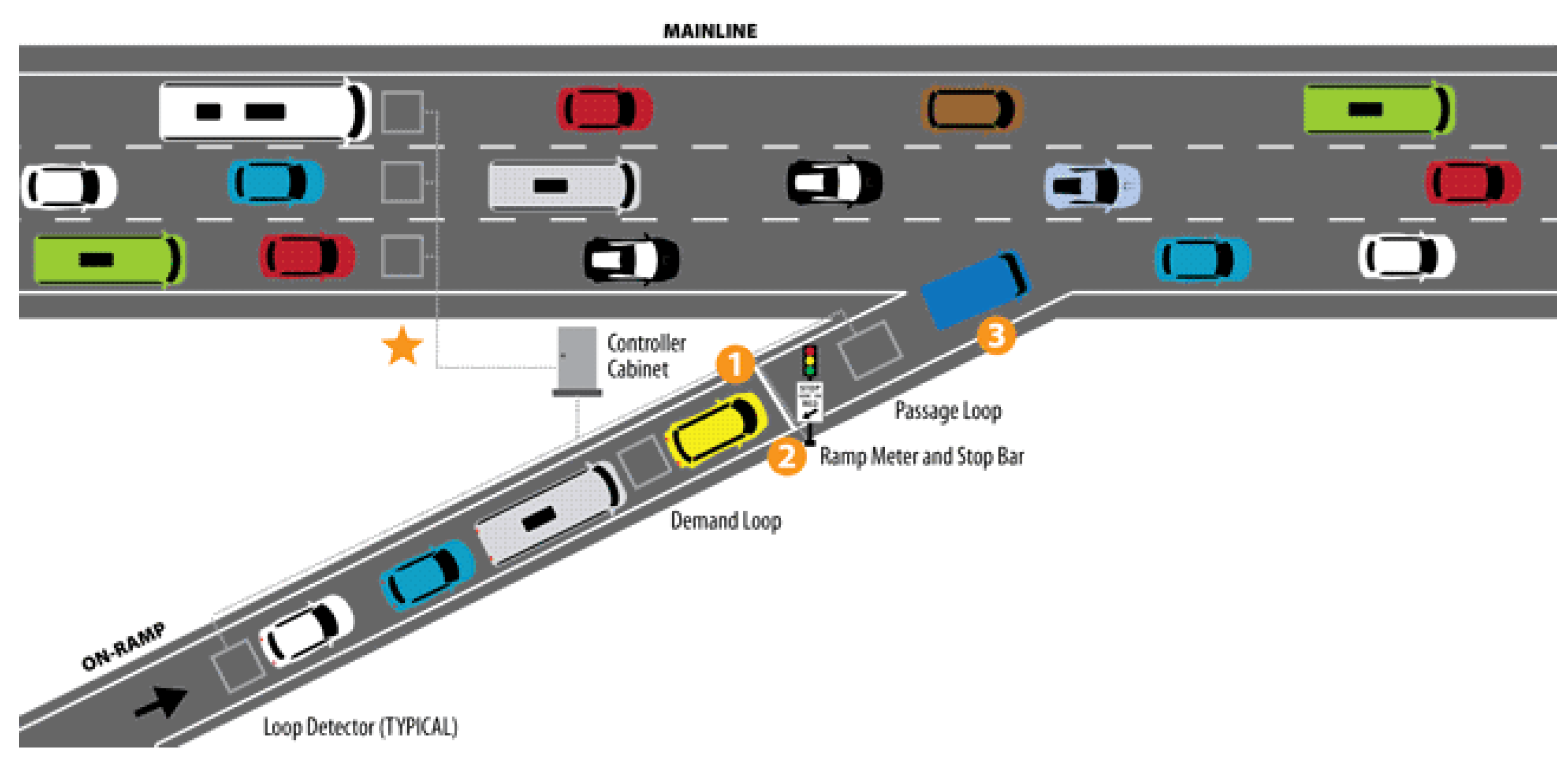
  • Conventional ramp metering relies on traffic state estimation from loop detectors that may not be accurate enough to represent real-time traffic conditions and provide detailed guidance for merging maneuvers;
  • The traffic signals may introduce unnecessary stop-and-go maneuvers to the on-ramp vehicles, which leads to extra travel time and excessive energy consumption, particularly for heavy-duty trucks;
  • The ramp metering system leaves ramp vehicles a much smaller space in which to adjust their speeds to merge into the mainline stream (due to mandatory stops at the meter), which increases the safety risks.
Recently, with the emerging connected and automated vehicle (CAV) technology, researchers have turned their focus to CAV-based cooperative ramp control algorithms that have the potential to avoid the aforementioned drawbacks. CAVs that broadcast information such as position and speed can improve traffic state estimation. Additionally, by elaborately designing their trajectories, CAVs can drive in a cooperative manner (e.g., a vehicle string with closely spaced gaps), which enables smooth merging. As a result, no stop-and-go maneuvering is needed (improved fuel economy), and safety is guaranteed by the automatic control algorithm. Additional benefits include the increased roadway capacity as the headway can be reduced compared to human-driven vehicles. Despite all the advantages of the CAV-based cooperative ramp control approach, many issues need to be addressed to further improve system performance:
  • Most of the existing studies only focus on the control of an isolated ramp merging area. The control effect on the down-/up-stream traffic is unknown. The uncoordinated traffic management across multiple ramps along a corridor may mitigate the benefit provided by the local optimal controller;
  • Numerous CAV-based cooperative ramp control algorithms have been developed to improve system mobility and to show environmental benefits, but very few of them are energy-oriented. In addition, most of them assume the first-come-first-serve (FCFS) sequencing strategy for simplicity, which cannot guarantee the system optimum;
  • Most of the research validates the system performance within a limited scope (e.g., using numerical simulation or applying the simulation with only a handful of CAVs). However, such validation methods may not be able to explore the long-term impacts on the traffic across a wide variety of scenarios.

1.3. Contributions of This Paper

In one of our previous works [3], we proposed the concept of the bilevel hierarchical ramp management system for CAVs, which can coordinate traffic operation along a corridor with multiple ramps. At the corridor level, the system-wide optimal inflow rate at each on-ramp is calculated. At the ramp level, the movements of the CAVs on both the mainline and the ramp are locally coordinated, while the regulation of the ramp inflow rate is based on the output from the corridor-level management. This study is regarded as the continuous effort to realize this concept and evaluate its respective performance. The major contributions of our proposed system are listed below:
  • To our best knowledge, this is the first of its kind corridor-wise cooperative ramp management system for CAVs, which can coordinate the merging maneuvers of vehicles both macroscopically and microscopically along a corridor with multiple ramps;
  • The proposed system is fully energy oriented. The merging sequence is determined directly and is based on energy consumption rather than FCFS. Energy-efficient speed trajectories are developed to regulate the ramp inflow rate;
  • We evaluate the proposed system for both gasoline vehicles and electric vehicles, with a real-world network coded in PTV VISSIM [4]. The system performance is evaluated in terms of mobility, safety, and environmental sustainability.

1.4. Organization of the Paper

The rest of the paper is structured as follows: Section 2 presents a comprehensive literature review of both traditional ramp metering approaches and CAV-based cooperative ramp control strategies. Section 3 illustrates the problem formulation and introduces the system architecture followed by a detailed description of each module in Section 4. The results of a case study using the microscopic traffic simulation are elaborated in Section 5, including a comparison with no ramp control and traditional ramp metering scenarios. The last section concludes our work and discusses future directions.

2. Literature Review

2.1. Ramp Metering

Ramp metering has been studied for decades. The existing strategies can be divided into two categories based on their scope: local ramp metering vs. system-wide ramp metering. Local strategies are only concerned with the traffic conditions at an isolated merging area, aiming to keep the balance between the mobility of the mainline traffic flow and the queue on the ramp without considering the down-/up-stream effect. The system-wide ramp metering strategies intend to balance the inflow rates of multiple ramps simultaneously in order to achieve corridor-wise traffic efficiency. Based on the control method, the existing system-wide ramp metering strategies can be further categorized into three classes: rule-based, optimization-based, and learning-based [3]. The rule-based approaches, such as the Bottleneck Algorithm [5] and the SWARM Algorithm [6], rely on simple hierarchical logic to adjust the metering rates, starting from the critical or downstream ramp merging areas. The optimization-based approaches, such as ALINEA [7], use automatic control techniques to drive the key traffic states into the designed level by introducing feedback. The learning-based approaches, which have emerged recently, construct end-to-end mapping between the metering rate and various traffic conditions using a significant amount of data and advanced machine learning techniques such as artificial neural networks (ANNs) and reinforcement learning (RL) [8,9,10].

2.2. Cooperative Ramp Merging for CAVs

The CAV-based cooperative ramp merging algorithms can coordinate CAV motion around the ramp merging area, including that of both the mainline and the on-ramp vehicles, by designing the optimal speed and acceleration. The basic idea is to control the longitudinal speeds of all of the vehicles in order to smoothly pass the merging zone with the required minimum time gap (i.e., maximizing the throughput). Very few algorithms consider the inflow rate regulation as ramp metering strategies do. Comprehensive reviews about the existing cooperative ramp control algorithms have been performed by Rios-Torres et al. [11], Scarinci et al. [12], and Zhao et al. [3] from different perspectives. In the following, we further comb the most recent studies, provide a summary of up-to-date algorithms, and elaborate on the recent research trends surrounding this topic.
The centralized approaches for the CAV coordination in the ramp area are defined if the trajectory planning and control design of the vehicles are decided globally by a centralized computing device such as roadside infrastructure and/or a transportation management center (TMC). The philosophy of conducting vehicle coordination in a centralized manner can be concluded as follows: (1) The on-board computer may not be able to provide enough computing power to support real-time control; (2) sensing locally or collecting information from a short range of the CAVs might not enough to understand global traffic status; (3) it could be more efficient to optimize and control the vehicles globally. As such, formulating the coordination of vehicles as an optimization problem is the most common idea [13,14,15,16,17,18,19,20,21,22]. The objective of the optimization problem can be the Driving-Time-To-Intersection (DTTI) [16], total travel time [11], and so on. Among these optimization-based methods, Cao et al. [18] applied an MPC-based approach to generate optimal merging paths for the vehicles in real-time. Jing et al. [19] proposed a cooperative multiplayer game-based optimization framework to achieve the minimum values for the global pay-off conditions. Rios-Torres et al. [20] presented an optimization framework and analytical closed-form solution enabling the online coordination of CAVs. Zhou et al. designed a trajectory planning algorithm based on the optimal control strategy under congested traffic conditions [21], and they further proposed a framework that recursively implemented the optimal control to accommodate the constantly changing external environment [22]. Other than solving the global optimization problem, hierarchy strategy is also commonly used for the centralized coordination of the highway merging vehicles [23,24,25]. For example, Ding et al. [25] addressed the problem through a rule-based adjusting algorithm to achieve a near-optimal merging sequence.
Different from centralized approaches that rely on roadside infrastructure and/or the TMC with infrastructure-to-vehicle (I2V) communication, distributed approaches are another way of coordinating CAVs in a ramp merging scenario. The distributed approaches use vehicle-to-vehicle (V2V) communication and make decisions on individual vehicles locally. Because distributed approaches do not rely on an exclusive computing center, they are usually more flexible and robust to disturbance from the environment. The idea of using distributed approaches for ramp merging control is to construct a platoon of vehicles. Therefore, mapping vehicles from ramp to mainline or vice versa is essential to the algorithm design [26,27,28], which uses the idea of virtual vehicle to realize such a mapping. Besides virtual vehicle mapping, other distributed approaches were also developed by different researchers. For example, Wang et al. proposed a distributed consensus-based CAV coordination system [29], and Huang et al. applied a distributed controller based on a feedback linearization method to ensure the inner-vehicle closed-loop stability of a virtual platoon with derived feedback gains [30].
While most aforementioned studies adopted a numerical simulation and/or microscopic traffic simulation, some researchers turn to the use of a game engine simulation to evaluate a cooperative ramp merging system, where more realistic vehicle dynamics can be implemented, and human-in-the-loop simulation can be conducted and compared to the proposed methodology [31]. For example, Liao et al. [32] proposed a co-simulation platform that combined both a microscopic traffic simulator (SUMO) and a game-engine (Unity). Specifically, Unity took over the sensing and control of all of the CAVs in the simulation, while SUMO handled the behaviors of all of the legacy vehicles.
Although there is a fair amount of research on CAV-based ramp merging control, and most of this research shows promising results via simulation tools, very few studies conduct real world experimentation. Milanés et al. [33] implemented their fuzzy logic-based controller to achieve Adaptive Cruise Control (ACC) at a low speed to emulate ramp merging in a congested traffic scenario. Based on vehicle-to-cloud communication, Liao et al. [34] applied their digital twin approach to the real world with three passenger vehicles. The Federal Highway Administration (FHWA) conducted a field implementation of cooperative lane change maneuvers with two CAVs and a human-driven vehicle [35]. Additionally, using V2X communications, similar field tests on highway merging scenarios have been conducted by the University of Minnesota [36], East Tennessee State University [37,38], and the Technical University of Madrid [39].
Finally, despite the rapid development of CAV technologies, the gradual and complex integration of automation and human-driving traffic systems will co-exist for in the long term. Therefore, research on ramp management under mixed traffic conditions is a challenging yet important topic. Sun et al. [40] proposed a cooperative decision-making mechanism to properly capture cooperative and non-cooperative behaviors in mixed traffic conditions and designed a bi-level optimization method to facilitate ramp merging. Rios-Torres et al. [41] studied the impact of the partial penetrations of CAVs on fuel consumption and traffic flow for ramp merging scenarios. Liao at al. [32] developed a game theory-based strategy that a determined dynamic merging sequence for optimal merging coordination between CAVs and human-driven vehicles.

3. Problem Formulation and System Architecture

3.1. Problem Formulation

3.1.1. Assumptions

In this paper, we make the following assumptions for system development. From the connectivity perspective:
  • All vehicles are Connected and Automated Vehicles (CAVs);
  • Vehicle information, such as position and speed, can be precisely captured and shared with each other as well as with the central traffic management unit via vehicle-to-vehicle (V2V) and vehicle-to-infrastructure (V2I) communications, respectively;
  • The communication delay and package loss are not considered.
From the control perspective:
  • Vehicles can receive and strictly follow the control instructions, i.e., acceleration or deceleration, from the central traffic management unit, which may be a roadside unit (RSU) deployed at each ramp. It can collect the data from CAVs within a certain range, estimate the traffic conditions, communicate with other traffic management units along the corridor, and calculate the detailed control instructions for the CAVs;
  • Cooperative maneuvers for ramp merging are only considered longitudinally. In the simulation study, lateral control is handled by default model behavior.

3.1.2. Vehicle Dynamics

In this study, we assume that all the CAVs are governed by second-order dynamics:
  p i ˙ = ν i ,   ν i ˙ = u i
where i   ( [ 1 ,   2 , ,   n ] ) is the vehicle index (from downstream to upstream); p and ν represent the position and speed of the vehicle, respectively; and u   denotes the acceleration/deceleration of the vehicle, which acts as the system input. To improve traffic efficiency, CAVs from on-ramp and/or mainline may be formed into a tight string (or group) at the merging area. Therefore, the states of the overall dynamic system of a group of CAVs can be defined as:
State: x = ( p 1 ,   p 2 ,   , p n , v 1 ,   v 2 ,   ,   v n ) T ;
If a reference vehicle exists in front of the whole group (e.g., the last vehicle in the preceding group), then
Observation: y = ( p r p 1 ,   p 1 p 2 ,   , p n 1 p n , v 1 ,   v 2 ,   ,   v n ) T
Otherwise,
Observation: y = ( p 1 p 2 ,   , p n 1 p n , v 1 ,   v 2 ,   ,   v n ) T
The state vector x includes the positions and speeds of all of the vehicles within the group to be controlled, and the observation vector contains the variables to be tracked using the reference signals. The first entry, p r p 1 , is added when a preceding vehicle exists in front of the whole group so that the group leader can track the position of the preceding vehicle plus a certain time gap. Therefore, the whole group is able to follow the preceding vehicle smoothly without collision. The system can be written as the following linear form:
x ˙ = A x + B u y = C x
where A = ( O 1 I O 2 ) , B = ( O 1 I ) , O 1 is an n × n zero matrix, O 2   is   an   n × 2 n   zero   matrix , and I is an n × n identical matrix; and
C = ( 1 ,   0 ,   ,   0 ,   0 ,   0 1 , 1 ,   0 ,   , 0 ,   0 ,   0 0 ,   1 , 1 , 0 ,   ,   0 , 0 , 0 0 ,   , 1 , 1 ,   0 , 0 , 0 O 1 I )   2 n × 2 n
if a preceding reference vehicle in front of the whole group exists. Otherwise,
C = ( 1 , 1 ,   0 ,   , 0 ,   0 ,   0 0 ,   1 , 1 , 0 ,   ,   0 , 0 , 0 0 ,   , 1 , 1 ,   0 , 0 , 0 O 1 I )   ( 2 n 1 ) × 2 n

3.1.3. Optimization Problem Formulation

We seek to keep the balance between the convergence speed of observation and the control effort. Therefore, we formulate an optimization problem in the quadratic form as follows:
min   J = 1 2 k = 0 N 1 { ( y k r k ) T Q ( y k r k ) + u k T R u k } + 1 2 ( y N r N ) T Q ( y N r N ) s . t . x k + 1 = A x k + B u k ,   y k = C x k A c c min u k A c c max ( ( p i ) k ( p i + 1 ) k ) G a p min
where r k   is the gap and speed reference to be tracked; Q and R define the weighting matrices of the objective function to be tuned, respectively, for the system outputs and inputs. [ A c c min , A c c max ]   is a feasible input range that a vehicle can achieve, and the boundary values can vary with respect to the vehicle speed. For example, A c c max at high speed is smaller than that at low speed (considering the power limit). G a p min is the safety gap to avoid collisions. If vehicle i and vehicle i + 1 are in the same lane (i.e., either both on the on-ramp or both on the mainline), this constraint should be strictly held. If vehicle i and vehicle i + 1 are in different lanes (e.g., one is on the mainline while the other is on the on-ramp), this constraint needs to be held when they arrive at (or very close to) the merging area.

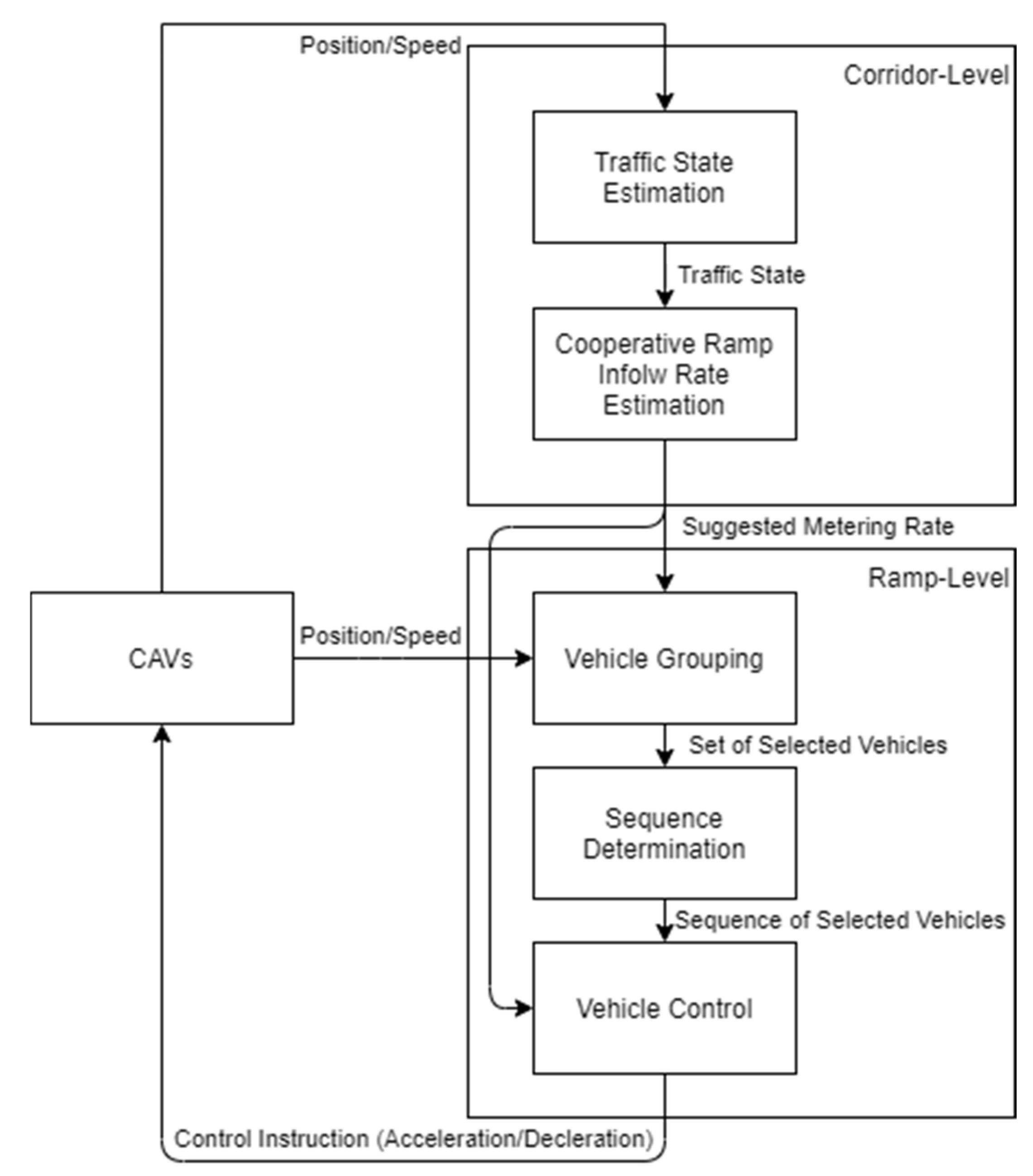
3.2. System Architecture

Figure 2 shows the bi-level system architecture of the proposed corridor-wise ramp management system, which is consistent with the one presented in our previous study [1]. At the corridor level, the developed system can calculate the corridor-wise optimal inflow rate at each on-ramp, which is based on the real-time traffic conditions and the estimated traffic states, to guarantee the efficiency of networked traffic. At the ramp level, there are three major modules: (1) grouping CAVs that are in spatial proximity (on both the mainline and on-ramp) as well as satisfying the optimal inflow rate suggested by the upper-level algorithm; (2) identifying the optimal merging sequence for the group of CAVs in terms of energy consumption; and (3) controlling the CAVs’ speeds in an energy-efficient manner with the model predictive control (MPC) approach to achieve the suggested metering rate at the same time.

4. Methodology

4.1. Corridor-Level: Metering Rate Estimation

The corridor-level control strategy is to maintain the optimal operation of the corridor by regulating the highway demand to be under the capacity. Therefore, the inflow rate of each ramp needs to be determined for boundary control, which also serves as the constraint for the ramp-level CAV motion control. In this paper, we consider the following for metering rate determination:
  • The free-flow condition of the mainline traffic should be maintained as much as possible;
  • The queue length at the on-ramps should be limited to avoid affecting the traffic on adjacent arterials;
  • The traffic condition should be able to recover from congestion (if any) as soon as possible;
  • Many existing corridor-wise ramp metering algorithms may take traffic conditions along the freeway into account and calculate coordinated metering rates for multiple ramps simultaneously. In this study, we adopted the Next Generation Stratified Ramp Metering Algorithm proposed by Geroliminis et al. [42] and applied it to the scenario with full CAV penetration. The objective is to balance the ramp waiting time and ramp inflow rate (or the demand and queue lengths at on-ramps) as well as the level of congestion on the mainline to delay the operation of the breakdown and to accelerate system recovery. The zone is defined as a segment of the highway between two consecutive mainline detector locations (in the traditional freeway system). For each section, there is a threat index that denotes the risk of becoming a bottleneck. Based on the indices, a controlled ramp can be determined. Figure 3 depicts the flow chart to identify the controlled ramp.
Using the zone identification information, the metering action matrixes are then defined in Table 1.

4.2. Ramp-Level: Movement Control and Rate Regulation

At the ramp-level control, three major modules are developed to enable the energy-efficient cooperative maneuvers of CAVs, i.e., vehicle grouping, sequence determination, and longitudinal speed control.

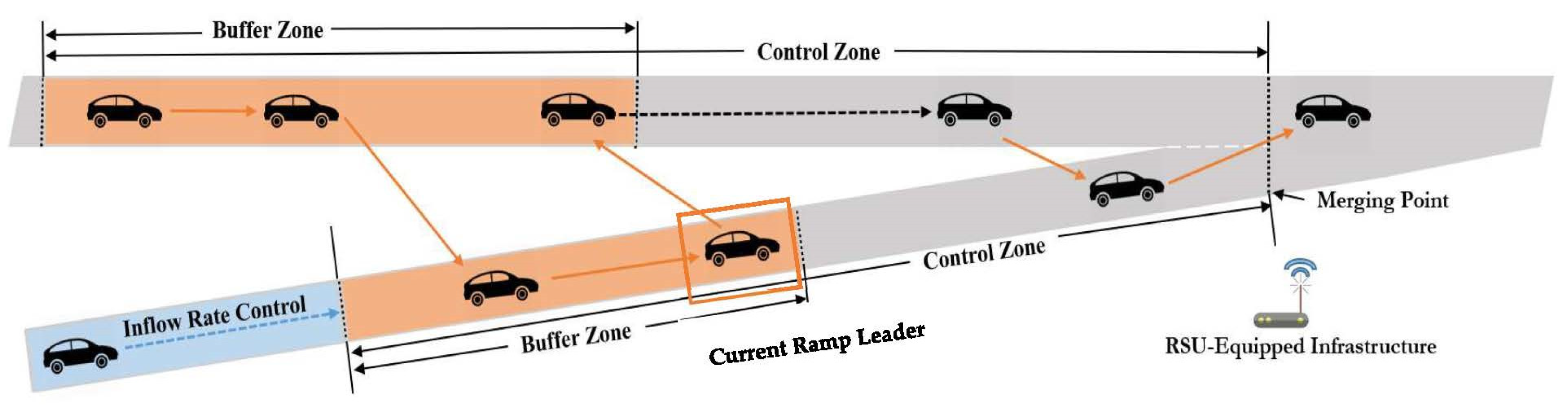
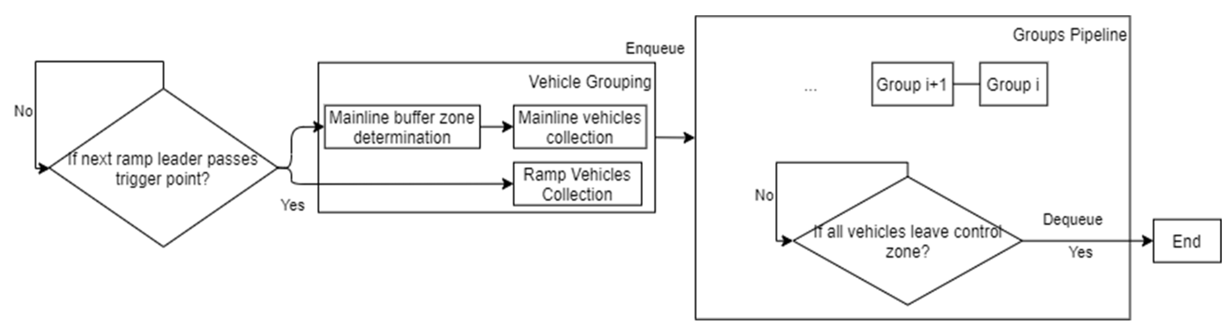
4.2.1. Vehicle Grouping

The vehicle grouping module is essential to ensure that the system can manage the continuous flow of traffic. We first define the control zone and the buffer zone shown in Figure 4. Both the mainline and the ramp have these two types of zones. The control zone is a segment of road from upstream of the merging area to the merging point. In the control zones, a roadside unit serves as a centralized traffic controller to receive and process the incoming information from the CAVs and sends control signals back to CAVs. The CAVs should then strictly follow the instructions such that a platoon with designed time gaps can be formed. The buffer zone, on the other hand, is located at the upstream portion of the control zone. In the buffer zones, the incoming vehicles are monitored and grouped.
Before describing the details of the event-based vehicle grouping strategy (see Figure 5), we should define the concept of a ramp leader. A ramp leader is an on-ramp vehicle that triggers the grouping process. A ramp leader is the first on-ramp vehicle that does not pass through the buffer zone and has not been controlled. We first assume that a group of controlled vehicles exists. The current ramp leader would then be the first vehicle on the ramp that is following the group. Once the ramp leader passes the downstream boundary of the on-ramp buffer zone or the trigger point, the grouping process is activated, and the vehicles in the buffer zones of both the mainline and ramp are collected as a group. At the same time, the current ramp leader is changed accordingly. If there is no group of vehicles that is under control, the first on-ramp vehicle is then the current ramp leader until it passes the trigger point. It should be noted that the control for a group happens right after the group is determined and continues until all the vehicles in the group drive through the control zone. It is possible that the new group is constructed while the previous group is still driving within the control zone. As a result, there could be multiple groups in parallel. Therefore, we use a pipeline architecture to store, process, and control the groups of the vehicles.
For each ramp, the length of the control zone and buffer zone are predefined to better adapt to the physical conditions. For the corresponding mainline area, the downstream side of the buffer zone is fixed, while the length of these zone changes dynamically according to real-time traffic conditions and the suggested metering rate from the corridor-level module. It is in this way that the vehicle grouping module is able to collect an appropriate number of mainline vehicles into a group. The length of the mainline buffer zone is determined with the following equation:
L m a i n = q m a i n q s u g g e s t e d · n / d m a i n
where q m a i n is the mainline traffic flow known from the corridor traffic condition; q s u g g e s t e d is the suggested on-ramp inflow rate assumed to be known; n is the number of on-ramp vehicles currently in the buffer zone; and d m a i n is the mainline density. It should be noted that a large number of vehicles in each group can affect the reliability of the centralized controller due to the degradation of the CAVs in a real-world situation, as discussed in [43]. This also exponentially increases the computational load for the control center (e.g., roadside equipment or traffic management center). Therefore, the proposed system limits the length of the buffer zone along the ramp for each group, which is set to be 100 m in this study. The length of the buffer zone along the mainline is designed to be adaptive.

4.2.2. Optimal Sequence Determination

After the CAVs are grouped, those within the same group will be controlled together. To enable efficient merging maneuvers, it is critical to determine the merging sequence of CAVs. In this research, we propose a three-step optimal sequence determination process as follows.
  • Feasible sequence generation: In this step, all of the possible entrance sequences of the CAVs in a group are first generated. As we assume that the vehicles in the same lane cannot overtake the preceding vehicles, the number of all of the feasible sequences equals to P ( m + n ,   n ) where P ( · ) is the permutation operation, and m is the number of mainline vehicles.
  • Linear quadratic tracking: The LQ tracking algorithm is applied to solve the optimization problem (Equation (3)). Different merging sequences correspond to different initial states of the system. Using the finite-horizon linear quadratic tracking algorithm, we are able to calculate the control inputs and the specific trajectories of the vehicles for each possible sequence. The Q and R are the weight matrices of the objective function. By tuning these two matrices, the convergence speed of observations and the control effort can be balanced. The control input can be obtained by solving the algebraic Riccati equation [44]:
    { S N = C T Q N C V N = C T Q N r N
    { S i = C T Q C + A T S i + 1 S i + 1 B ( R + B T S i + 1 B ) 1 B T S i + 1 A V i = { A T A T S i + 1 B ( R + B T S i + 1 B ) 1 B T } V i + 1 + C T Q r i
    { K i = ( B T S i + 1 B + R ) 1 B T S i + 1 A K i ν = ( B T S i + 1 B + R ) 1 B T
    where N is the predefined finite horizon; i is the discrete-time index for each iteration; K i is the feedback gain; and K i ν is the feed-forward gain. S i ,   V i ,   K i , and K i ν can be found iteratively backward in time. The control input is then given by μ i =   K i x k + K i ν V i . Therefore, for each possible sequence, the speed profile can be calculated.
  • Energy consumption estimation: Based on the calculated speed profile under each possible sequence, the corresponding energy consumption can be estimated for the vehicle with different classifications (such as passenger cars, transit buses, or trucks) and powertrains (e.g., internal combustion engines or electric motors). In the simulation, we assume that all the vehicles are passenger cars and that the road grade is trivial, and we will evaluate the system performance of both gasoline-powered vehicles and electric vehicles. In addition, for gasoline-powered vehicles, we refer to the model proposed by [45]:
    f V = b 0 + b 1 v + b 2 v 2 + b 3 ν 3 + a ( c 0 + c 1 v + c 2 v 2 )
    where b i and c i are the model parameters calibrated by different driving conditions and v and a are the speed and acceleration of the vehicles. Specifically, b 0 = 0.1569 , b 1 = 2.450 × 10 2 , b 2 = 7.415 × 10 4 , b 3 = 5.975 × 10 5 , c 0 = 0.07224 , c 1 = 9.681 × 10 2 , and c 2 = 1.075 × 10 3 .
For electric vehicles, the model developed in our previous work [46] is used:
P = f ( v , a ) = l 0 + l 1 ν cos ( α ) + l 2 ν sin ( α ) + l 3 v a + l 5 v 2 cos ( α ) + l 6 ν 2 sin ( α ) + l 7 v 4
where l i is the model parameter calibrated by different driving conditions, and α is the road grade (rad). Specifically, l 0 = 3.146 , l 1 = 0.940 , l 2 = 1.237 , l 3 = 1.521 , l 4 = 4.104 × 10 2 , l 5 = 3.289 × 10 2 , l 6 = 4.427 × 10 5 , and l 7 = 0.677 .
Finally, the sequence with the least aggregated energy consumption is selected as the optimal scenario, and the control algorithm in the next section will be applied to this sequence.

4.2.3. Longitudinal Speed Control

As mentioned previously, we focused on the longitudinal speed control to engage the energy-efficient cooperative ramp merging of CAVs in this study. There are two parts of this module. The first part is an MPC controller, which applies a receding-horizon LQ tracking algorithm to control the vehicles in each group. To match the predicted energy consumption in the optimal sequence determination step, the same control parameters are used as in the associated finite-horizon LQ tracker. Additionally, multiple MPC controllers are running in parallel to control multiple groups in the pipeline. The second part of the speed control module is a ramp inflow rate controller. Based on the suggested inflow rate from corridor-level control, the speed of the ramp leader within each group is regulated to fulfill the boundary constraint. Towards this end, we first calculate the estimated time of arrival (ETA) of the ramp leader, assuming it would follow the preceding vehicle without any external control. The Intelligent Driver Model (IDM) [47] is used for the prediction of its ETA.
ν ˙ = a ( 1 ( ν ν 0 ) δ ( s * ( ν Δ ν ) s ) 2 )
s ( ν Δ ν ) = s 0 + ν T + ν Δ ν 2 a b
where ν 0 = 30   m / s is the desired speed; s 0 = 2   m is the minimum spacing; T = 2 s is the desired time headway; a = 0.73 m/ s 2 is the maximum vehicle acceleration; b = 1.67 m/ s 2 is the comfortable braking deceleration; and σ = 4 is the acceleration exponent.
We then compare the predicted ETA with the recommended time of arrival (RTA) based on the suggested inflow rate from the corridor-level control, using the following equation:
t e x p e c t = n r a m p q s u g g e s t e d
where n r a m p is the number of ramp vehicles within the previous group, and q s u g g e s t e d is the metering rate from the corridor-level module.
If the ETA is smaller than the RTA, the ramp leader should be controlled to slow down and pass the trigger point (i.e., the downstream boundary of the on-ramp buffer zone in Figure 3) at the recommended time. If the ETA is larger than the RTA, the ramp leader is not controlled. To achieve better energy consumption, we apply the dynamic eco-driving strategy (given the target arrival time) from our previous work [48] for the speed control of the ramp leader. Dynamic programming is used to obtain the least energy consumption solution. Please refer to [48] for more details regarding the algorithm if interested.
Figure 6 presents an example to illustrate the proposed longitudinal speed control strategy. As shown in the figure, the mainline CAVs in group 1 generate enough gaps for the three on-ramp CAVs to merge in. The blue dash curve shows the predicted trajectory of Ramp Leader 1. Because the ETA is earlier than the RTA, Ramp Leader 1 is controlled to slow down. Once Ramp Leader 1 hits the trigger point, group 2 of both the mainline and ramp vehicles are identified and controlled suing MPC. As for Ramp Leader 2, its movement is not controlled before it passes the trigger point because its ETA is later than the RTA. Similarly, group 3 is also constructed when Ramp Leader 2 reaches the trigger point. At this time, CAVs from group 2 are still in the control zone. Therefore, CAVs in both group 2 and group 3 are in the pipeline and are controlled by different MPC controllers in parallel.

5. Simulation Study

In this section, we evaluate our proposed ramp management system in a microscopic traffic simulator, PTV VISSIM. Compared to a numerical simulation-based study, microscopic traffic simulation can offer more realistic interactions between the agents and the environment. Additionally, the online simulation is able to consider the evolution of traffic conditions and the accumulated effect of traffic management strategies.

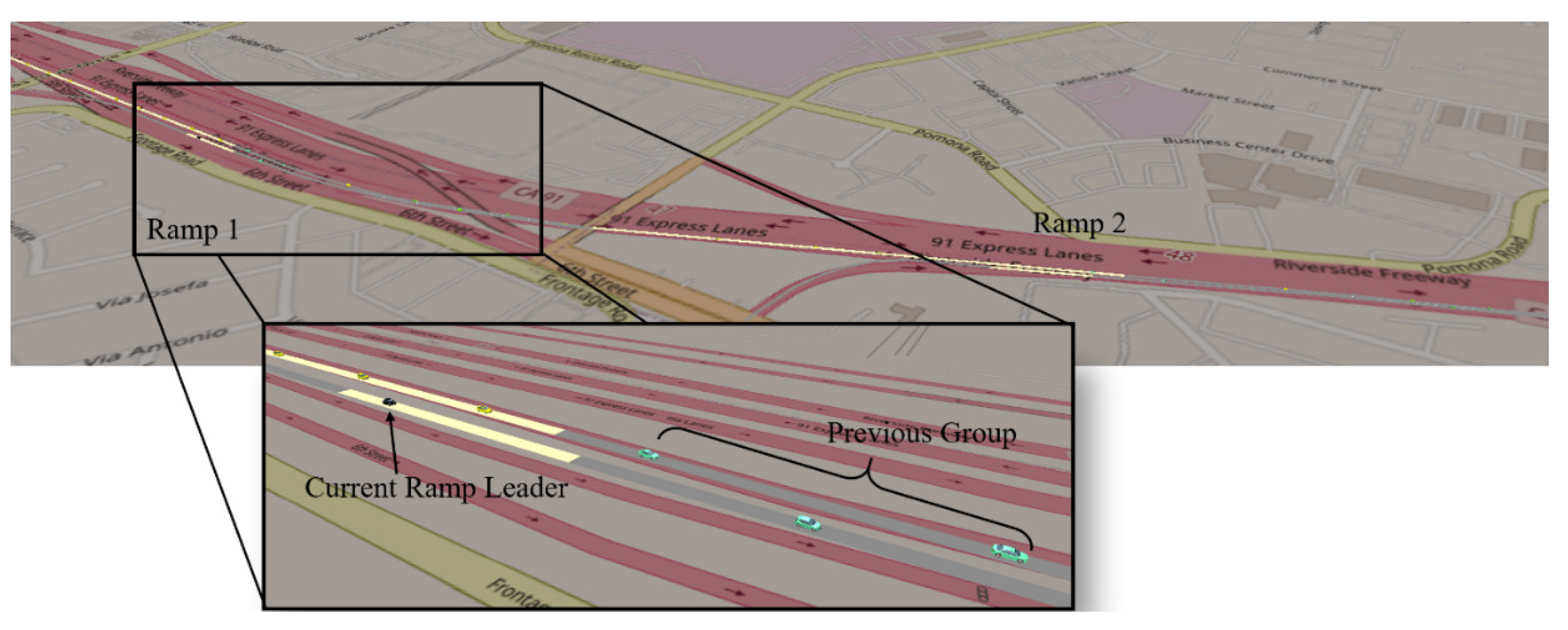
5.1. Simulation Setup

We coded a real-world highway road segment along California State Route 91 (SR-91) with two ramps (Serfas Club Dr. on-ramp and Paseo Grande on-ramp) in the simulation environment (see Figure 7), where the total length of the highway segment was 1.5 miles. Using the application programming interface (API) provided by VISSIM, we could access the CAV statuses, which represent the shared information with the centralized traffic management infrastructure, and we could also control the longitudinal dynamics of the assigned CAVs by sending the desired acceleration/deceleration. As for those vehicles in the buffer zones, the default car following model in VISSIM, Widemann99 [49], was used to reduce computational loads. The lane change maneuver was controlled using the lateral behavior model provided by VISSM with the default parameters. The desired speeds for both the mainline and merging traffic were 74.6 mph (or 120 km/h), and the initial speed of the on-ramp vehicles entering the network was set to be 11.2 mph (or 18 km/h). The weight matrices for the quadratic objective function, i.e., Q and R, were tuned manually to adapt to the road network. We set the Q and R to be diagonal matrices. The position weight between both two mainline vehicles was 5, the position weight between both two ramp vehicles was 30, and the position weight between one ramp vehicle and one mainline vehicle was 6; the speed weight for the mainline vehicle was 50 and 30 for the on-ramp vehicle; the acceleration weight of the mainline vehicles was 2800 and for the on-ramp vehicles, it was 2500.
We also set two control groups (with human-driven vehicles) for comparison: the first one applied the ramp metering strategy with the same metering rate at each ramp as the test group, which was obtained from the corridor-wise SRM algorithm; the second one had no external control for merging maneuvers (i.e., no metering). There was no communication or driving assistance for the vehicles in either control group.
Simulation scenarios were set up to evaluate different traffic conditions by defining the average input volume from each network entrance, including mainline, Ramp 1, and Ramp 2. Within the 20-min simulation period, two phases of traffic demands existed. In Phase 1 (from 0 to 600 s), we set the mainline input to be 1200 passenger-car-unit/hour/lane (pcu/hr/ln), the Ramp 1 input to be 500 pcu/hr/ln, and the Ramp 2 input to be 200 pcu/hr/ln. In Phase 2 (from 600 to 1200 s), we set the mainline input to be 1200 pcu/hour/lane, the Ramp 1 input to be 300 pcu/hr/ln, and the Ramp 2 input to be 200 pcu/hr/ln. During each phase, the incoming vehicles were randomly spawned into the network, and after Phase 2, the simulation would continue running until the network cleared up.

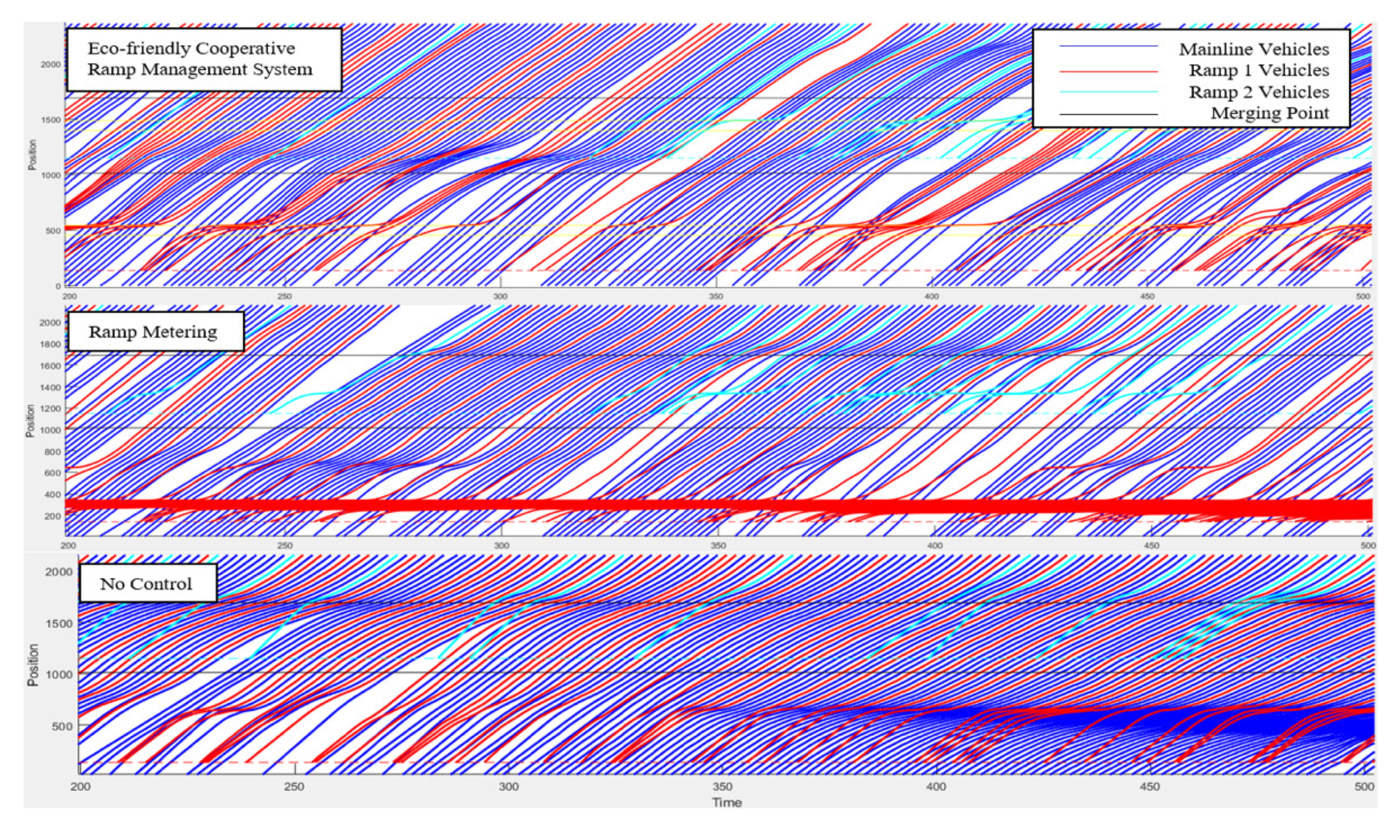
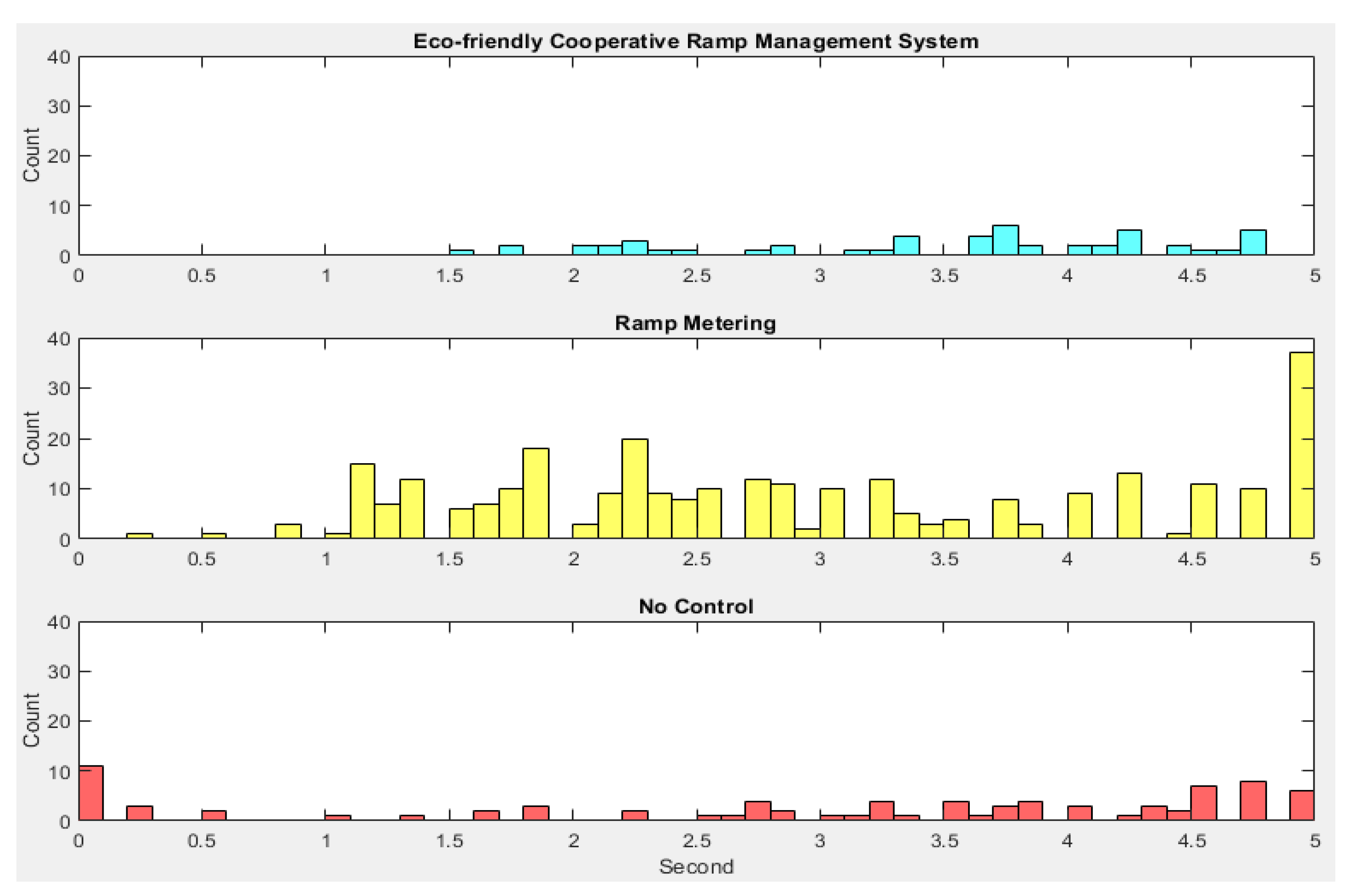
5.2. Results Comparison for Gasoline Vehicles

Figure 8 shows the example trajectories of the CAVs (from 200 to 500 s) generated from VISSIM. In the top subplot, the proposed eco-friendly cooperative ramp management system can not only smooth the speed profiles of the ramp vehicles but can also mitigate the potential congestion of downstream mainline traffic by regulating the inflow rates of both on-ramps. In the middle subplot, although the mainline traffic is not affected by the merging vehicles, traffic on Ramp 1 significantly slows down and forms a long queue due to ramp metering. In the case of no control, as shown in the bottom subplot, the merging vehicles cause shockwaves on the mainline, which propagates upstream and eventually results in congestion on both the mainline and Ramp 1.
To investigate the performance of the proposed system, mobility is measured by the network efficiency
Q = V M T V H T
where VMT denotes the vehicle-miles traveled of all CAVs in the network, and VHT denotes the vehicle-hours traveled in the network. The energy consumption for the gasoline vehicles (with Equation (8)) is estimated in the unit of miles per gallon (mpg), and the results are shown in the following table.
As it can be observed from Table 2, the overall mobility of the proposed system is increased by 48.6% and 79.4% compared to the ramp metering case and no control case, respectively. Additionally, vehicles can achieve higher mpg with the proposed ramp management system compared to both cases (35.1% and 0.8%, respectively) due to the mitigation of traffic congestion. In addition, it is the case that although ramp metering can significantly mitigate mainline congestion, it is detrimental to on ramp traffic in terms of both mobility and energy, particularly for Ramp 1.
Safety performance is analyzed using the time-to-collision (TTC) distributions (obtained from the Surrogate Safety Assessment Model [50]) as shown in Figure 9. The x-axis denotes the TTC in second, and the y-axis denotes the number of events in the corresponding bins. The figure shows that there is no event with TTC being less than 1.5 s for the proposed ramp management system. This indicates that the proposed system would result in a trivial amount of potential conflicts and significantly improve safety performance, compared to the other two cases.

5.3. Results Comparison for Electric Vehicles

The simulation of electric vehicles was also conducted in this study. For the EV analysis, we used kWatt/100 mile as the energy consumption measurement. The results are shown in Table 3.
The mobility performance of the scenario using EVs is similar to the Gasoline vehicles, and the trend of energy performance is also the same. The major reasons that cause the mobility differences between electric vehicles and gasoline-powered vehicles fall into two categories: First, the different energy consumption models that were applied may change the determination of the entrance sequence. Second, when controlling the ramp leader to slow down, the energy models play role in the optimization process. Although proving similar mobility improvement, due to the regenerative braking feature of electric vehicles, a smaller level of energy saving can be achieved.

6. Conclusions and Future Work

6.1. Theoretical and Practical Implications

In this paper, we proposed a corridor-wise eco-friendly cooperative ramp management system for connected and automated vehicles (CAVs). At the macroscopic level (corridor level), the optimal inflow rate for each ramp along the corridor was calculated by the Next Generation Stratified Ramp Metering Algorithm. At the microscopic level (ramp level), we developed a dynamic control strategy for CAVs to achieve rate regulation, group determination, and motion control in an energy-efficient manner. Using the microscopic traffic simulation in VISSIM, the effectiveness of the system was demonstrated in terms of safety, mobility, and environmental sustainability compared to cases of human-driven vehicles with and without ramp metering control. To understand the robustness of the proposed system with respect to different powertrain technologies, we also evaluated the performance for scenarios using both gasoline vehicles and electric vehicles.
Compared to conventional ramp metering, the proposed ramp management system may improve the mobility of gasoline-powered vehicles and electric vehicles by 48.6% and 56.7%, respectively. It may also reduce energy consumption by 35.1% (for gasoline-power vehicles) and 24% (for electric vehicles). Compared to no control scenarios, the proposed ramp management system may enhance the average travel speed of gasoline-powered vehicles by 79.4% and electric vehicles by 89.1%. At the same time, energy can be saved by 0.8% and 2.5% for gasoline-power vehicles and electric vehicles, respectively.
From the implementation perspective, since the proposed system is targeted at corridor-level traffic management, it should be adopted in a centralized manner (e.g., vehicle-to-cloud) or a hybrid manner (e.g., vehicle-to-roadside and roadside-to-cloud), depending on the existing infrastructure and costs. To maximize the potential of the system, all of the vehicles involved should be connected and automated (at least with level 1 automation) vehicles (CAVs), which may be considered as a strong assumption. One possible solution is to further promote the adoption of CAVs and enhance digital infrastructure while planning and deploying dedicated multi-ramp freeway stretches to enable the proposed system.

6.2. Limitations and Future Work

There are several limitations of the current work which will serve as our future research directions to improve this work:
  • As aforementioned, our current system requires all the traffic participants to be connected and automated vehicles so that they are able to share the current status and execute the designed command. As one of the future steps, the system will be extended to handle more complex and near-term scenarios and mixed traffic, where not only CAVs but also legacy vehicles should be considered;
  • Another limitation is the model of communication. To simplify this problem, the current system assumes there is no communication delay. However, in the real world, the delay and package loss may impact both the performance and reliability of the system. Therefore, we plan to simulate the system with a more realistic communication model (e.g., Omnet++) and investigate how the degradation of the communication quality would affect the proposed system. If necessary, solutions to handle the scenarios with low quality communication will be considered.

Author Contributions

Conceptualization, Z.Z. and G.W.; methodology, Z.Z. and G.W.; software, Z.Z.; validation, Z.Z.; formal analysis, Z.Z., G.W. and M.B.; investigation, Z.Z., G.W. and M.B.; resources, G.W. and M.B.; writing—original draft preparation, Z.Z. and G.W.; writing—review and editing, Z.Z., G.W., and M.B.; visualization, Z.Z. and G.W.; supervision, G.W. and M.B.; project administration, G.W. and M.B.; funding acquisition, G.W. and M.B.; All authors have read and agreed to the published version of the manuscript.

Funding

This research was funded by the National Center for Sustainable Transportation (NSCT), grant number USDOT Grant 69A3551747114.

Institutional Review Board Statement

Not applicable.

Informed Consent Statement

The contents of this paper reflect only the views of the authors, who are responsible for the facts and the accuracy of the data presented herein.

Data Availability Statement

Dryad, Dataset, https://doi.org/10.6086/D10M3D (accessed on 28 July 2021).

Acknowledgments

This study is funded by the National Center for Sustainable Transportation (NCST). The contents of this paper reflect only the views of the authors, who are responsible for the facts and the accuracy of the data presented herein. The authors would also like to thank to Ziran Wang from the Toyota Info Technology Center for his strong support and constructive comments on the study.

Conflicts of Interest

The authors declare no conflict of interest.

References

  1. Zhao, Z.; Wu, G.; Wang, Z.; Barth, M.J. Optimal Control-Based Eco-Ramp Merging System for Connected and Automated Electric Vehicles. arXiv 2019, arXiv:1910.07620. [Google Scholar]
  2. Federal Highway Administration. Ramp Metering: A Proven, Effective Strategy. Available online: https://ops.fhwa.dot.gov/publications/fhwahop14021/sec1.htm (accessed on 28 July 2021).
  3. Zhao, Z.; Wang, Z.; Wu, G.; Ye, F.; Barth, M.J. The state-of-the-art of coordinated ramp control with mixed traffic conditions. In Proceedings of the IEEE Intelligent Transportation Systems Conference (ITSC), Auckland, New Zealand, 27–30 October 2019; pp. 1741–1748. [Google Scholar]
  4. PTV VISSIM. PTV Group. Available online: https://www.ptvgroup.com/en/solutions/products/ptv-vissim/ (accessed on 28 July 2021).
  5. Jacobson, L.N.; Henry, K.C.; Mehyar, O. Real-Time Metering Algorithm for Centralized Control; Transportation Research Board: Washington, DC, USA, 1989. [Google Scholar]
  6. Paesani, G.; Kerr, J.; Perovich, P.; Khosravi, F.E. System wide adaptive ramp metering (SWARM). In Merging the Transportation and Communications Revolutions; Abstracts for ITS America Seventh Annual Meeting and Exposition: Washington, DC, USA, 1997. [Google Scholar]
  7. Papageorgiou, M.; Hadj-Salem, H.; Blosseville, J.M. ALINEA: A local feedback control law for on-ramp metering. Transp. Res. Rec. 1991, 1320, 58–67. [Google Scholar]
  8. Zhang, H.M.; Ritchie, S.G. Freeway ramp metering using artificial neural networks. Transp. Res. Part C Emerg. Technol. 1997, 5, 273–286. [Google Scholar] [CrossRef]
  9. Lu, C.; Huang, J. A self-learning system for local ramp metering with queue management. Transp. Plan. Technol. 2017, 40, 182–198. [Google Scholar] [CrossRef]
  10. Schmidt-Dumont, T.; Van Vuuren, J.H. Decentralized reinforcement learning for ramp metering and variable speed limits on highways. IEEE Trans. Intell. Transp. Syst. 2015, 14, 1. [Google Scholar]
  11. Rios-Torres, J.; Malikopoulos, A.A. A survey on the coordination of connected and automated vehicles at intersections and merging at highway on-ramps. IEEE Trans. Intell. Transp. Syst. 2016, 18, 1066–1077. [Google Scholar] [CrossRef]
  12. Scarinci, R.; Heydecker, B. Control concepts for facilitating motorway on-ramp merging using intelligent vehicles. Transp. Rev. 2014, 34, 775–797. [Google Scholar] [CrossRef]
  13. Athans, M. A Unified Approach to the Vehicle-Merging Problem; Transportation Research Board: Washington, DC, USA, 1968; pp. 123–133. [Google Scholar]
  14. Levine, W.S.; Athans, M. On the optimal error regulation of a string of moving vehicles. IEEE Trans. Autom. Control 1966, 11, 355–361. [Google Scholar] [CrossRef]
  15. Awal, T.; Kulik, L.; Ramamohanrao, K. Optimal traffic merging strategy for communication-and sensor-enabled vehicles. In Proceedings of the 16th International IEEE Conference on Intelligent Transportation Systems (ITSC 2013), The Hague, The Netherlands, 6–9 October 2013; pp. 1468–1474. [Google Scholar]
  16. Raravi, G.; Shingde, V.; Ramamritham, K.; Bharadia, J. Merge algorithms for intelligent vehicles. In Next Generation Design and Verification Methodologies for Distributed Embedded Control Systems; Springer: Berlin/Heidelberg, Germany, 2007; pp. 51–65. [Google Scholar]
  17. Xie, Y.; Zhang, H.; Gartner, N.H.; Arsava, T. Collaborative merging strategy for freeway ramp operations in a connected and autonomous vehicles environment. J. Intell. Transp. Syst. 2017, 21, 136–147. [Google Scholar] [CrossRef]
  18. Cao, W.; Mukai, M.; Kawabe, T.; Nishira, H.; Fujiki, N. Cooperative vehicle path generation during merging using model predictive control with real-time optimization. Control Eng. Pract. 2015, 34, 98–105. [Google Scholar] [CrossRef]
  19. Jing, S.; Hui, F.; Zhao, X.; Rios-Torres, J.; Khattak, A.J. Cooperative game approach to optimal merging sequence and on-ramp merging control of connected and automated vehicles. IEEE Trans. Intell. Transp. Syst. 2019, 20, 4234–4244. [Google Scholar] [CrossRef]
  20. Rios-Torres, J.; Malikopoulos, A.A. Automated and cooperative vehicle merging at highway on-ramps. IEEE Trans. Intell. Transp. Syst. 2016, 18, 780–789. [Google Scholar] [CrossRef]
  21. Zhou, Y.; Chung, E.; Bhaskar, A.; Cholette, M.E. A state-constrained optimal control based trajectory planning strategy for cooperative freeway mainline facilitating and on-ramp merging maneuvers under congested traffic. Transp. Res. Part C Emerg. Technol. 2019, 109, 321–342. [Google Scholar] [CrossRef]
  22. Zhou, Y.; Cholette, M.E.; Bhaskar, A.; Chung, E. Optimal vehicle trajectory planning with control constraints and recursive implementation for automated on-ramp merging. IEEE Trans. Intell. Transp. Syst. 2018, 20, 3409–3420. [Google Scholar] [CrossRef]
  23. Schmidt, G.K.; Posch, B. A two-layer control scheme for merging of automated vehicles. In Proceedings of the 22nd IEEE Conference on Decision and Control, San Antonio, TX, USA, 14–16 December 1983; pp. 495–500. [Google Scholar]
  24. Ran, B.; Leight, S.; Chang, B. A microscopic simulation model for merging control on a dedicated-lane automated highway system. Transp. Res. Part C Emerg. Technol. 1999, 7, 369–388. [Google Scholar] [CrossRef]
  25. Ding, J.; Li, L.; Peng, H.; Zhang, Y. A rule-based cooperative merging strategy for connected and automated vehicles. IEEE Trans. Intell. Transp. Syst. 2019, 21, 3436–3446. [Google Scholar] [CrossRef]
  26. Uno, A.; Sakaguchi, T.; Tsugawa, S. A merging control algorithm based on inter-vehicle communication. In Proceedings of the 199 IEEE/IEEJ/JSAI International Conference on Intelligent Transportation Systems (Cat. No. 99TH8383), Tokyo, Japan, 5–8 October 1999; pp. 783–787. [Google Scholar]
  27. Lu, X.Y.; Hedrick, J.K. Longitudinal control algorithm for automated vehicle merging. Int. J. Control 2003, 76, 193–202. [Google Scholar] [CrossRef]
  28. Chou, F.C.; Shladover, S.E.; Bansal, G. Coordinated merge control based on V2V communication. In Proceedings of the 2016 IEEE Vehicular Networking Conference (VNC), Columbus, OH, USA, 8–10 December 2016; pp. 1–8. [Google Scholar]
  29. Wang, Z.; Wu, G.; Barth, M.J. Distributed consensus-based cooperative highway on-ramp merging using V2X communications. In Proceedings of the WCX World Congress Experience, Detroit, MI, USA, 10–12 April 2018. [Google Scholar]
  30. Huang, Z.; Zhuang, W.; Yin, G.; Xu, L.; Luo, K. Cooperative Merging for Multiple Connected and Automated Vehicles at Highway On-Ramps via Virtual Platoon Formation. In Proceedings of the 2019 Chinese Control Conference (CCC), Guangzhou, China, 27–30 July 2019; pp. 6709–6714. [Google Scholar]
  31. Wang, Z.; Wu, G.; Boriboonsomsin, K.; Barth, M.J.; Han, K.; Kim, B.; Tiwari, P. Cooperative ramp merging system: Agent-based modeling and simulation using game engine. SAE Int. J. Connect. Autom. Veh. 2019, 2, 115–128. [Google Scholar] [CrossRef]
  32. Liao, X.; Zhao, X.; Wu, G.; Barth, M.J.; Wang, Z.; Han, K.; Tiwari, P. A game theory based ramp merging strategy for connected and automated vehicles in the mixed traffic: A unity-sumo integrated platform. arXiv 2021, arXiv:2101.11237. [Google Scholar]
  33. Milanés, V.; Godoy, J.; Villagrá, J.; Pérez, J. Automated on-ramp merging system for congested traffic situations. IEEE Trans. Intell. Transp. Syst. 2010, 12, 500–508. [Google Scholar] [CrossRef] [Green Version]
  34. Liao, X.; Wang, Z.; Zhao, X.; Han, K.; Tiwari, P.; Barth, M.; Wu, G. Cooperative ramp merging design and field implementation: A digital twin approach based on vehicle-to-cloud communication. In IEEE Transactions on Intelligent Transportation Systems; IEEE: Piscataway, NJ, USA, 2020. [Google Scholar]
  35. Raboy, K.; Ma, J.; Stark, J.; Zhou, F.; Rush, K.; Leslie, E. Cooperative Control for Lane Change Maneuvers with Connected Automated Vehicles: A Field Experiment. In Proceedings of the Transportation Research Board 96th Annual Meeting, Washington, DC, USA, 8–12 January 2017. [Google Scholar]
  36. Hussain, S.; Peng, Z.; Hayee, M.I. Development and Demonstration of Merge Assist System Using Connected Vehicle Technology; Center for Transportation Studies, University of Minnesota: Minneapolis, MN, USA, 2019. [Google Scholar]
  37. Ahmed, M.S.; Hoque, M.A.; Rios-Torres, J.; Khattak, A. Freeway merge assistance system using dsrc. In Proceedings of the 2nd ACM International Workshop on Smart, Autonomous, and Connected Vehicular Systems and Services, Snowbird, UT, USA, 20 October 2017; Association for Computing Machinery: New York, NY, USA, 2017; pp. 83–84. [Google Scholar]
  38. Ahmed, M.S.; Hoque, M.A.; Rios-Torres, J.; Khattak, A. A cooperative freeway merge assistance system using connected vehicles. arXiv 2018, arXiv:1805.00508. [Google Scholar]
  39. Sanchez-Mateo, S.; Perez-Moreno, E.; Jimenez, F.; Serradilla, F.; Ruiz, A.C.; Tamayo, S.D.L.F. Validation of an assistance system for merging maneuvers in highways in real driving conditions. In Proceedings of the 16th European Automotive Congress (EAEC), MINSK, Belarus, 7–11 October 2019. [Google Scholar]
  40. Sun, Z.; Huang, T.; Zhang, P. Cooperative decision-making for mixed traffic: A ramp merging example. Transp. Res. Part C Emerg. Technol. 2020, 120, 102764. [Google Scholar] [CrossRef]
  41. Rios-Torres, J.; Malikopoulos, A.A. Impact of partial penetrations of connected and automated vehicles on fuel consumption and traffic flow. IEEE Trans. Intell. Veh. 2018, 3, 453–462. [Google Scholar] [CrossRef]
  42. Geroliminis, N.; Srivastava, A.; Michalopoulos, P. Development of the Next Generation Stratified Ramp Metering Algorithm Based on Freeway Density; Center for Transportation Studies: Minneapolis, MN, USA, 2011. [Google Scholar]
  43. Yao, Z.; Xu, T.; Jiang, Y.; Hu, R. Linear stability analysis of heterogeneous traffic flow considering degradations of connected automated vehicles and reaction time. Phys. A Stat. Mech. Appl. 2021, 561, 125218. [Google Scholar] [CrossRef]
  44. Bemporad, A.; Morari, M.; Dua, V.; Pistikopoulos, E.N. The explicit linear quadratic regulator for constrained systems. Automatica 2002, 38, 3–20. [Google Scholar] [CrossRef]
  45. Kamal, M.A.; Mukai, M.; Murata, J.; Kawabe, T. Ecological vehicle control on roads with up-down slopes. IEEE Trans. Intell. Transp. Syst. 2011, 12, 783–794. [Google Scholar] [CrossRef]
  46. Ye, F.; Wu, G.; Boriboonsomsin, K.; Barth, M.J. A hybrid approach to estimating electric vehicle energy consumption for ecodriving applications. In Proceedings of the 2016 IEEE 19th International Conference on Intelligent Transportation Systems (ITSC), Rio de Janeiro, Brazil, 1–4 November 2016; pp. 719–724. [Google Scholar]
  47. Kesting, A.; Treiber, M.; Helbing, D. Enhanced intelligent driver model to access the impact of driving strategies on traffic capacity. Philos. Trans. R. Soc. A Math. Phys. Eng. Sci. 2010, 368, 4585–4605. [Google Scholar] [CrossRef] [PubMed] [Green Version]
  48. Jin, Q.; Wu, G.; Boriboonsomsin, K.; Barth, M.J. Power-based optimal longitudinal control for a connected eco-driving system. IEEE Trans. Intell. Transp. Syst. 2016, 17, 2900–2910. [Google Scholar] [CrossRef]
  49. Lu, Z.; Fu, T.; Fu, L.; Shiravi, S.; Jiang, C. A video-based approach to calibrating car-following parameters in VISSIM for urban traffic. Int. J. Transp. Sci. Technol. 2016, 5, 1–9. [Google Scholar] [CrossRef] [Green Version]
  50. Gettman, D.; Pu, L.; Sayed, T.; Shelby, S. Surrogate Safety Assessment Model and Validation: Final Report; Federal Highway Administration, Office of Safety Research and Development: McLean, VA, USA, 2008.
Figure 1. Illustration of ramp metering [2].
Sustainability 13 08557 g001
Figure 2. System architecture of the proposed ramp management system.
Sustainability 13 08557 g002
Figure 3. Flowchart of corridor-wise ramp metering rate determination, where i in the current section is ID; k is the number of consecutive downstream sections;   P i is the congestion threat index of the current section; M(i, i − k) is the net inflow between the two locations i and i − k, defined as the sum of on-ramp volumes minus the sum of off-ramp volumes plus the capacity flow difference for all ramps between the two locations.
Sustainability 13 08557 g003
Figure 4. Definition of the zones of the proposed ramp-level control.
Sustainability 13 08557 g004
Figure 5. Flowchart of the vehicle grouping.
Sustainability 13 08557 g005
Figure 6. Illustration of the example vehicles’ trajectories.
Sustainability 13 08557 g006
Figure 7. Simulation environment.
Sustainability 13 08557 g007
Figure 8. Trajectories of the CAVs for the three cases.
Sustainability 13 08557 g008
Figure 9. Distributions of TTC.
Sustainability 13 08557 g009
Table 1. Conditions to estimate the suggested ramp inflow rate [29].
ConditionIndex = 0, downstream not controlled rampIndex = 0/1, downstream controlled rampIndex = 1, downstream not controlled rampIndex = 2
TypeUncongested Ramp MeteringControlled Ramp MeteringControlled Ramp MeteringCongested Ramp Metering
Suggested Ramp Inflow Rate c h ( i ) q ( i ) d i Δ t i d i [ d j r t ( j ) ] Δ t j d j r t 1 ( i ) K 1 ( T t w ( i ) τ w ) + K 2 T t k ( i ) r t 1 ( i ) + K 1 T t w ( i ) ,
if   T t w ( i ) < 0
r t 1 ( i ) + K 2 T t k ( i ) ,
otherwise
where c h ( i ) is the uncongested capacity; q(i) is the mainline demand; d i is the ramp demand; j is the downstream controlling ramp id;   r t ( j ) is the current suggested metering rate of the location j; Δ t i = T c r i t w t ( i ) , where T c r i t is the ramp delay constraint, and w t ( i ) is the current maximum waiting time at ramp i; K 1 and K 2 are contribution parameters depicting the importance of breakdown on the ramp and on mainline; τ w is the safe time-to-breakdown defined for the ramp; T t w ( i ) and T t k ( i ) are the estimated time remaining to congestion on the mainline and ramp. The values of the parameters and the variables are calculated based on historical or real-time data.
Table 2. Simulation results of mobility and energy performance for gasoline vehicles.
Mobility (mph)Energy (mpg)
the Bigger the Better
Eco-friendly Cooperative Ramp Management SystemOverall59.10 (48.6%) (79.4%)44.40 (35.1%) (0.8%)
Mainline62.17 (−4.9%) (107.3%)41.45 (10.0%) (−4.0%)
Ramp 153.14 (210.0%) (−7.7%)51.75 (119.2%) (8.4%)
Ramp 250.60 (−2.7%) (14.9%)65.12 (112.1%) (56.0%)
Ramp MeteringOverall39.7632.87
Mainline65.4037.67
Ramp 117.1423.61
Ramp 252.0330.70
No ControlOverall32.9544.05
Mainline29.9843.19
Ramp 157.5547.73
Ramp 244.0541.74
Table 3. Simulation results of mobility and energy Performance for electric vehicles.
Mobility (mph)Energy (kWatt/100 mile)
the Smaller the Better
Optimal ControlOverall62.31 (56.7%) (89.1%)40.91 (−24.0%) (−2.5%)
Mainline65.28 (−1.8%) (117.7%)44.15 (−7.6%) (3.5%)
Ramp 157.14 (233.4%) (−0.7%)33.75 (−54.2%) (−13.0%)
Ramp 254.03 (3.8%) (22.7%)29.04 (−44.9%) (−37.3%)
Ramp MeteringOverall39.7653.84
Mainline65.4047.76
Ramp 117.1473.68
Ramp 252.0352.72
No ControlOverall32.9541.98
Mainline29.9842.64
Ramp 157.5538.80
Ramp 244.0546.33
Publisher’s Note: MDPI stays neutral with regard to jurisdictional claims in published maps and institutional affiliations.

