1. Introduction
Environmentally friendly lubricants and process materials are used in a wide range of technical applications. Especially in mobile machinery, efforts are being made to increase the use of bio-lubricants. Every year, a considerable amount of lubricants ends up in the environment due to accidents and leakages. According to estimates by the Federal Environment Agency, the annual return rate of used hydraulic oils in Germany is around 75%. Conversely, this means that 25% of used hydraulic oil ends up in the environment or is not properly disposed. With a sales volume of around 105,000 t of hydraulic oil annually, this amounts to 26,250 t of oil [
1].
Hydraulic oils cause serious damage when leaked into the environment. Accidents involving mobile machinery have the greatest impact. For each accident involving a mobile machine, several hundred liters of hydraulic oil can be released into the environment. These incidents lead to contamination of the affected area. Most frequent causes of accidents are hose defects and leaking hose couplings, with a 50% share. Of all fluid leakages on construction sites 74% involve hydraulic oil [
2], and 30% of these leakages comprise a volume of more than 20 L. Soils contaminated by hydraulic oil must subsequently be cleaned up at great expense to restore them to their natural state. Bio-based hydraulic oils minimize the environmental impact through their biodegradability and lack of toxicity and lead to more sustainable hydraulic systems.
In the following the requirements for bio-based lubricants according to DIN EN 16807 [
3] are presented. Thus, bio-based lubricants must contain at least 25% renewable components. This also has a positive influence on the life cycle assessment of fluids. The standard also stipulates a biodegradability of 60% within 28 days. In practice, it has been confirmed that the biodegradability of bio-based hydraulic oils is approx. 90% after three weeks, while that of mineral oil is only 36% in comparison [
4]. Reducing toxicity follows the objective of protecting life in different environments, especially in water (aquatic environment) and on land (non-aquatic environment). In order to reduce toxicity of lubricants, it is important to perform standardized test methods. One example is a testing method according to EN ISO 14593 [
5], which examines the growth inhibition of freshwater algae. In addition to environmentally friendly properties, bio-based hydraulic oils must meet the performance requirements of the respective application. Compatibility with components such as sealing materials and non-ferrous metals is also of particular importance for a safe and reliable operation.
In forestry in Germany, the usage of bio-based hydraulic fluids is regulated by Forest Stewardship Council (FSC) Directive [
6]. The guideline does not refer to the lubricant itself but is rather a manual for implementations of sustainable forestry. This is expressed in ten principles, which are relevant to the development and production of biolubricants. Primarily, the impact on the environment and the preservation of forests should be emphasized. For lubricants, this implies a requirement for the use of environmental friendly and biodegradable lubricants that are used in forestry machinery and thus potentially come into direct contact with its environment.
Since 2013, the use of environmentally friendly hydraulic fluids has been mandatory for maritime shipping in the United States of America. The Vessel General Permit (VGP) [
7] applies this regulation. Under this law, all merchant vessels operating in U.S. seas after 19 December 2013 must be driven with environmentally friendly hydraulic fluids. This regulation applies to all lubricants that could potentially come into contact with seawater. In this case, environmental compatibility means a minimum of toxicity, easy biodegradability and no bio-accumulation.
In terms of technical characteristics, bio-based hydraulic oils are largely comparable with mineral oil-based fluids and must meet the technical requirements of DIN ISO 15380 [
8].
Compared to mineral oils, bio-hydraulic oils have more favorable rheological properties. The lower viscosity-temperature dependency of bio-hydraulic oils are mentioned here in particular. The viscosity index (VI) is used as a measure of the correlation between viscosity and temperature. As the viscosity index increases, the dependence of viscosity on temperature decreases. A low temperature dependence of viscosity is especially advantageous in mobile applications. In this field, the oil temperature often varies over a wide temperature range. From a cold start in winter at nearly −40 °C, to operation under full load in summer, where the oil can reach up to 120 °C. Due to low temperature dependence, safe and reliable operation of the system can be guaranteed in all applications. Bio-hydraulic oils of the Hydraulic Oil Environmental Ester Synthetic (HEES) class generally have a viscosity index of 150–220, while that of mineral oil is around 100 [
9].
By adding additives, mineral oil-based hydraulic oils can also achieve a VI of greater than 140. These are mostly polymer chains, which are present as bundles in the base oil at low temperatures. These bundles are distributed colloidal in the fluid. As the temperature rises, molecules expand and unravel. Due to this expansion, the contact area with neighboring molecules increases. This increases internal friction in the fluid. The resulting long polymer chains can be mechanically broken due to high shear rates and thus lose their effectiveness as viscosity improvers. Bio-based hydraulic oils inherently have a high viscosity index due to their chemical structure, so an addition of viscosity improvers is not necessary.
A disadvantage of these ester-based fluids is their higher sensitivity to hydrolysis and oxidation processes, as well as their incompatibility with widely used sealing materials [
10].
With a view to decreasing energy resources and increasing problems associated with CO2 emissions and global warming, there is a growing interest in reducing the fuel consumption of machines in all sectors. Triggered by this trend, the power density of hydraulic systems and their components continue to increase. This results in higher pressures and temperatures as well as lower oil volumes in the system. As a result, hydraulic fluid is subjected to higher thermal and mechanical loads. Due to this, knowing thermal properties of the system becomes increasingly important. High temperatures in hydraulic systems favor mechanisms of oil ageing, hence reducing the service life of hydraulic components, precision of the machine and intervals of changing hydraulic oil. Additionally, an important aspect is that the fluid’s viscosity is influenced by the temperature in various components of a hydraulic system. This affects the power losses in hydraulic systems, including hydraulic-mechanical losses such as pipe friction and volumetric losses such as leakage losses. In a complex hydraulic system as that of a mobile excavator, these types of losses only occur simultaneously.
To evaluate the economic efficiency of a machine, the total costs of ownership (TCO) are used. The TCO are divided into costs for acquisition and costs for operation of the machine. An energy-efficient hydraulic system has several advantages. For example, on the one hand, less energy is needed to operate the system, and on the other hand, less power loss has to be dissipated in the form of heat. The losses occurring in a hydraulic system can be divided into two types: Component-dependent and system-related losses.
In mobile machinery, there is a variety of concepts for increasing functionality and energy efficiency. Component efficiencies and especially the system’s architecture and its intelligent control have a significant influence on the overall efficiency of a drive system.
The currently used and developed concepts can be divided into two main categories. Firstly, concepts that concern the system’s structure and secondly those addressing intelligent controls. One example for intelligent control concepts is independent metering where independent valves realize the inlet and outlet control edges. By decoupling the control edges, volume flow paths can be selected much more flexibly and recuperative operations can be realized.
Regarding the system’s structure, in addition to the development of various hybrid structures, a trend towards electrification and digitization of mobile machines can be observed [
11].
Furthermore, there are concepts combining multiple conceptions. The STEAM concept [
12] for example uses a hydraulic system combining different concepts regarding the system structure to improve energy efficiency of a mobile excavator.
This article presents bio-based hydraulic oil as a sustainable alternative to conventional mineral oil and discusses the potential of the influence of fluid viscosity on the efficiency of a mobile working machine. The temperature distribution of the hydraulic oil during operation in a mobile machine is within a wide temperature range, which is particularly advantageous for usage of bio-hydraulic oil due to its higher viscosity index, supporting a more stable working process. In addition to temperature deviation between different components, temperature variations over time occur in various working applications.
The use of biohydraulic oils in mobile working machines represents a further sustainable concept for increasing efficiency. This concept can be listed into the presented concepts presented. In the context of this article, the experimental investigation of the savings potential through the use of biohydraulic oil in a crawler excavator is analyzed. For this purpose, the fuel consumption of the test excavator is analyzed for automated digging cycles with mineral oil and biohydraulic oil respectively. The “dig and dump” cycle represents a work task mainly performed during operational life of a crawler excavator. The fuel consumptions are then compared in relation to different operating temperatures of the excavator. In order to exploit the rheological advantages of biohydraulic oil over mineral oil, a biohydraulic oil is selected which is designed for the temperature distribution of the excavator’s hydraulic system.
For this purpose, a biohydraulic oil is selected which is fitted to the temperature distribution of an excavator’s hydraulic system, to take advantage on the rheological properties of biohydraulic fluids.
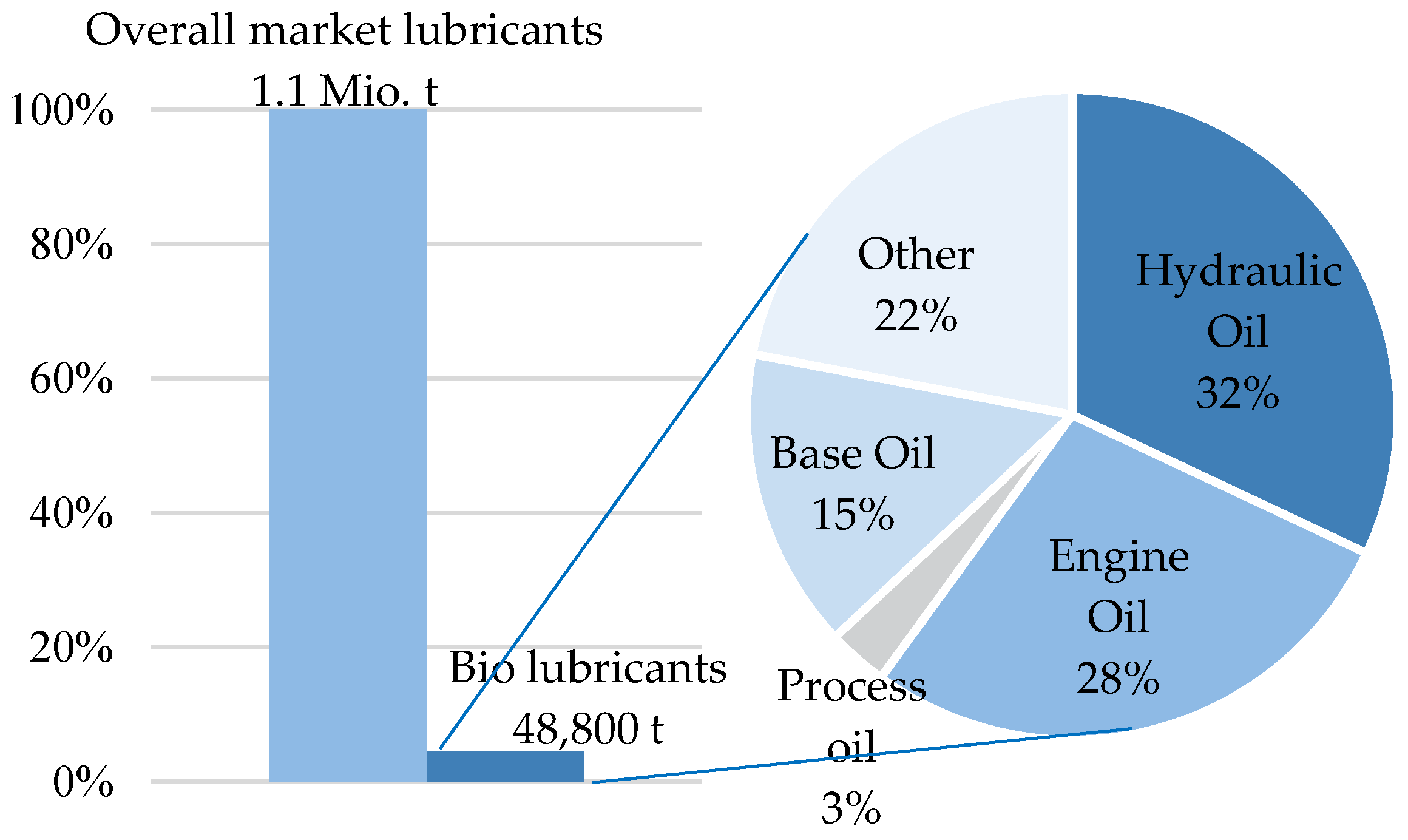
The sales market for bio-hydraulic oils has stalled in the last decades.
Figure 1 shows market sales of lubricants in Germany. Total annual sales of lubricants are about 1.1 million tons, of which only about 4.3% (47,500 t) are bio-based lubricants. This statistic shows that bio-based lubricants are still a niche product and that their market potential is high. About 10% (105,000 t) of all lubricants sold are hydraulic oils. A look at the distribution of bio-based lubricants shows that 30% (14,250 t) are hydraulic oils. This means that hydraulic oils represent the largest sales volume in the field of bio-lubricants, followed by motor oils (28%). In the hydraulic industry itself, about 14% of all oils used are bio-based. The substitution potential of bio-based hydraulic oils is to be rated significantly higher [
4,
13]. Potential fuel savings from the use of biohydraulic oil in mobile machinery may increase current market sales.
Obstacles to use bio-based hydraulic oils are mainly due to a lack of experience in documenting the technical performance of oils. Moreover, much higher prices compared to conventional mineral oils are one of the most significant obstacles. Furthermore, in almost all sectors, there are no legal requirements stipulating the use of bio-based lubricants. The converting process to bio-based hydraulic oil is another complex barrier. Finally, due to different structures of mineral oils and bio-oils, incompatibilities between the oils can occur, which can lead to deposits and high-molecular intermediates, for example. According to DIN ISO 15380 [
8], only a maximum of 2% residual oil may be present in an entire hydraulic system after oil change, so that proper functions of the system can be guaranteed. In order to achieve the residual oil content, hydraulic systems must be flushed several times, which is associated with high effort and costs.
2. Power Dissipation of Mobile Machines
In order to be able to evaluate possible fuel savings through the use of biohydraulic oils, an analysis of the power losses in mobile machinery is necessary. This analysis forms the base for subsequent consideration of possible fuel savings through usage of biohydraulic oils in mobile machines.
Energy conversion and conduction in components of hydraulic systems is always associated with losses. Losses are caused by individual components of the hydraulic system. The losses that occur are converted into heat, which is dissipated by the hydraulic fluid used. According to component-dependency, losses can be divided into volumetric and hydraulic-mechanical losses. These types of losses are influenced by viscosity and viscosity index of the used pressure medium, and also depend on the operating point of the system. The selected main circuit configuration of the hydraulic system determines the system dependent losses, for example the throttling losses in a system with resistance control.
According to [
14], the power loss
results from the drive power
and the efficiency
of the hydraulic system (Equation (1)):
In [
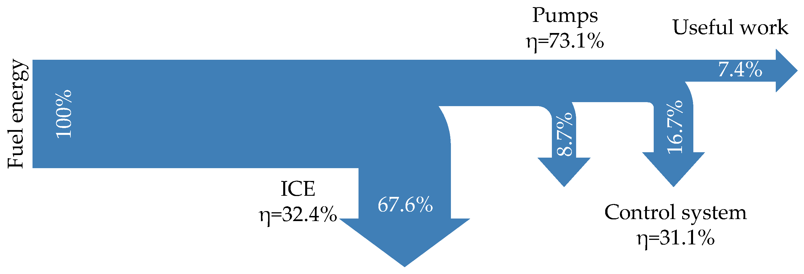
15], losses of a wheeled excavator are shown as a function of the fuel energy used. The results are based on an experimental performance of a 90° digging cycle. In addition to losses in relation to total input power, individual efficiencies of different subsystems are also discussed.
Figure 2 shows the results of the analysis using a Sankey diagram. In relation to the fuel energy fed in, only about 7.4% is converted into usable work for the digging process. The largest losses occur when chemical energy of the fuel is converted into mechanical work by the combustion engine. This mechanical energy is then transferred via a shaft to the hydraulic pump, which converts the mechanical power into hydraulic power. The control system in this case consists of valves, pipes and hoses. The actuators convert the useful work. Also shown are efficiencies of individual subsystems in relation to the energy supplied. It is obvious that the individual efficiency of the control system is below the internal combustion engine’s (ICE) efficiency. In addition to system-related losses, losses occurring in the control system also include those in valves and in piping systems, whose viscosity dependence is investigated in this work. In the following, viscosity dependence of volumetric and hydraulic-mechanical losses are discussed that occur in the hydraulic system of an excavator.
2.1. Volumetric Losses
Compression losses as well as internal and external leakage lead to volumetric losses. In the case of pumps and motors, hydraulic fluid flows from the high-pressure side to the low-pressure side through function-related gaps between hydraulic unit components that move relatively to each other. These gap losses occur, for example, at the ring surface of a piston-bushing contact of a pump or motor. Laminar flows through circular cross-sections are characterized by Equation (2), the Hagen-Poiseuille equation. It describes the loss volume flow
,
is the radius of the gap and
the respective length.
describes the dynamic viscosity of the fluid.
is the pressure difference occurring across the gap [
16]:
At a high viscosity
, volumetric losses decrease due decreasing gap volume flow. Conversely, filling losses occur because the pump sucks in liquid less well due to high friction losses. To avoid cavitation, the so-called permissible starting viscosity must not be exceeded. Cavitation can cause damage to the pump and leads to filling losses, which increase volumetric losses [
16].
2.2. Hydraulic-Mechanical Losses
Friction losses in tribological contacts of hydraulic components and in flowing hydraulic fluids are called hydraulic-mechanical losses. A high viscosity, for example at low temperatures, leads to an increase in friction in the fluid. Hydraulic-mechanical losses occur in fluid-flow areas of the system, for example in hydraulic resistances. These flow losses cause pressure losses and a heating of the fluid. High flow velocities due to large volume flows and small flow cross sections increase pressure losses. Furthermore, flow losses depend on the geometry of the flow leading components. It is taken into account by the corresponding resistance coefficients and characteristic curves when a hydraulic system is designed.
At relative velocities between two surfaces of tribological contacts shear stress occurs. Especially when the viscosity of the pressure fluid at high temperatures falls below the minimum required for application. As a result, no load-bearing lubricating film can be generated and mixed friction occurs between moving components [
17]. Operation in the area of mixed friction can be minimized and the occurrence of mixed friction prevented through a higher fluid viscosity. Thus, viscosity influences the efficiency of hydraulic systems as well as the service life of components and the availability of the entire hydraulic system.
2.3. Energy Losses of a Hydraulic System
Energy losses in hydraulic systems lead to a heat input into the fluid. This results in a temperature increase and, consequently, in viscosity decrease. The loss mechanisms in hydraulic systems are discussed in more detail below in order to explain the effects of the experiments carried out. The losses are identified in the considerations by the heating of the hydraulic fluid. Therefore, the largest heat inputs into the fluid are identified and analyzed accordingly. Any differences between the temperature distribution during operation with mineral oil and biohydraulic oils are pointed out.
Based on the excavator’s main circuit of the hydraulic system, energy losses of the system can be divided into different system components.
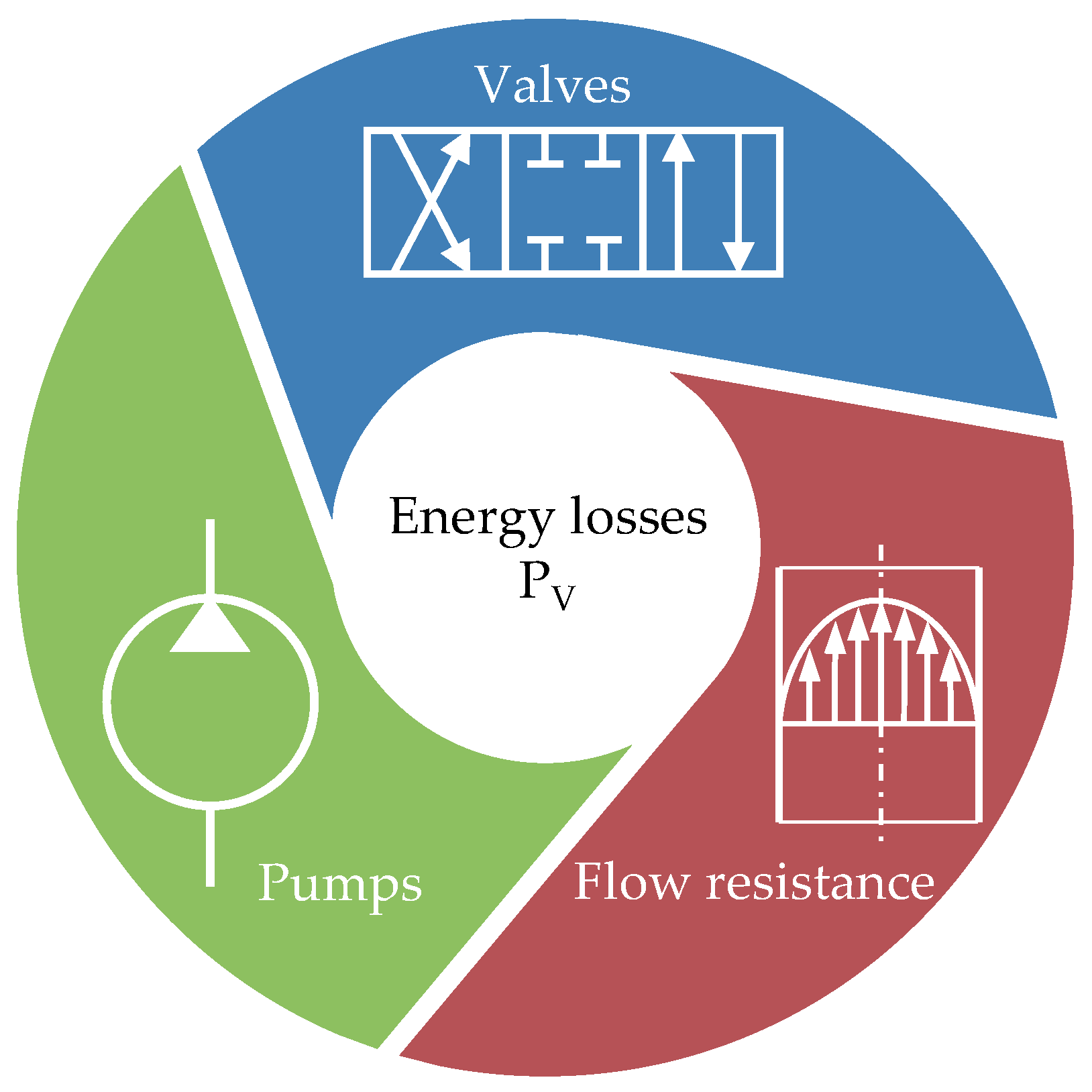
Figure 3 shows various main loss mechanisms of a hydraulic system. Energy losses occur mainly in pumps and motors, valves and piping. Further losses are caused, for example, by filters and coolers. Energy losses usually occur in the system in a superimposed form. Three main loss mechanisms are explained in more detail below.
2.3.1. Pumps
Hydraulic displacement units can be characterized by volumetric, hydraulic-mechanical and total efficiency. All leakage losses in hydraulic units are summarized in form of volumetric losses. Leakage losses are mainly caused by two fluid volumes with different pressure levels. In this case, for example, in contacts with narrow gaps. In addition to leakage losses, hydraulic-mechanical losses occur. The mechanism includes mixed friction, as well as pressure losses due to friction shear and throttling at cross-sectional changes [
16].
The dependence of the volumetric and hydraulic mechanical efficiency of various pump designs on the fluid viscosity was investigated in [
18]. In this context, various hydraulic oils with different base oils were considered with regard to their influence on efficiency of displacement units. A dependence of fluid viscosity on the efficiency was found, which led to an increase of up to 3% of overall efficiency compared to conventional HLP mineral oils. The energy saving was achieved by using a native ester in comparison to a mineral oil in a vane pump. The viscosity index of the ester was 239 and that of the mineral oil 105 [
18].
2.3.2. Valves
Energy losses in directional control valves can be divided in terms of losses due to separation of flow from the control edge in the turbulent range and into losses due to wall friction. For a given nominal size, this pressure loss depends on the size of the volume flow, on the design and on operating viscosity. Directional control valves can be approximated as an orifice resistance. The viscosity dependence of the losses is not included in this consideration. In the test excavator’s hydraulic system, spool valves are used to direct volume flow to the desired actuator. Each hydraulic consumer is controlled by its own spool valve, so that power losses can be assigned to individual actuators.
2.3.3. Flow Resistance
On one hand, flow resistance in straight pipes is caused by friction of fluid near the wall and on the other hand by internal friction of the fluid itself. The pressure losses
in pipelines can be described with Equation (3). The resistance coefficient
is function of Reynolds number, which has a viscosity dependence. A high viscosity at low temperatures leads to increasing friction of the fluid. Hydraulic-mechanical losses increase in all areas of the system, where a volume flow exists, for example in hydraulic resistances. These flow losses cause pressure losses and heating of the fluid. High flow velocities
due to large volume flows and small flow cross-sections d increase pressure losses. Furthermore, flow losses depend on the pipe’s length
and diameter
. When designing a hydraulic system, corresponding resistance coefficients and characteristic curves are taken into account:
In the hydraulic system of mobile machines, flow resistances result from fluid routing to the consumers, from fluid deflections in the system and from rapid changes of cross-sections.
2.4. Test Setup
In this article, the efficiency of a mobile machine concerning the use of biohydraulic oils is considered. The following sections presents the test setup for the corresponding measurements. In order to qualify these correlations, standardized tests are carried out with a crawler excavator using mineral oil and biohydraulic oil. The results of these investigations are then compared with regard to their fuel consumption. In order to exploit advantageous rheological properties of biohydraulic oil in comparison to mineral oil based hydraulic fluid, a biohydraulic oil is selected for the machines operating temperature. For this, the fluid viscosity is adjusted to the highest temperature in the hydraulic system during the cycle. The measurement results from the reference cycle with mineral oil are analyzed as a base for the selection of biohydraulic oil. Both the biohydraulic oil and the mineral oil exhibit Newtonian behavior. This means that the fluids have a linear viscous flow behavior. The shear rate is therefore proportional to the shear stress.
2.4.1. Test Excavator
In
Figure 4, the specifications of the test excavator are shown. The crawler excavator belongs to the class of compact excavators. It is driven by tracks. In addition to linear actuators, which are required for digging, the excavator has actuators for additional operations which are not regarded in the investigations. The test excavator is equipped with hydraulic-mechanical one-circuit load-sensing system, which is controlled by electro-hydraulic pilot valves instead of the usually implemented hydraulic joysticks. The load-sensing system is a hydraulic control system in which pressure or volume flow of the hydraulic pump are adjusted to the conditions required from the consumer. This system is widely adopted in hydraulic systems of mobile working machines.
An electro-hydraulic prototype control allows completely automated and reproducible digging cycles. The main pump supplies the hydraulic actuators. During operation, the highest load pressure in the system is detected and the displacement volume of the pump is adjusted accordingly. The pump is a variable displacement axial piston pump.
The total weight of the machine is 1790 kg. The gross power of the diesel engine is 12 kW. The nominal bucket filling level is 36 L. The hydraulic tank consists of 15 L and its complete hydraulic system capacity amounts to 21 L. The hydraulic system is operated with a hydraulic mineral oil of class HLP 46.
2.4.2. Test Cycle
The typical construction site activity of an excavator consists of the sum of four different load cycles. These include “grading” with a ratio of 10%, “driving” with 20%, “idling” with 30% and a load cycle “digging” with 40% of the total task [
19]. The executed test cycle is based on test cycles defined by Japan Construction Mechanization Association (JCMA) [
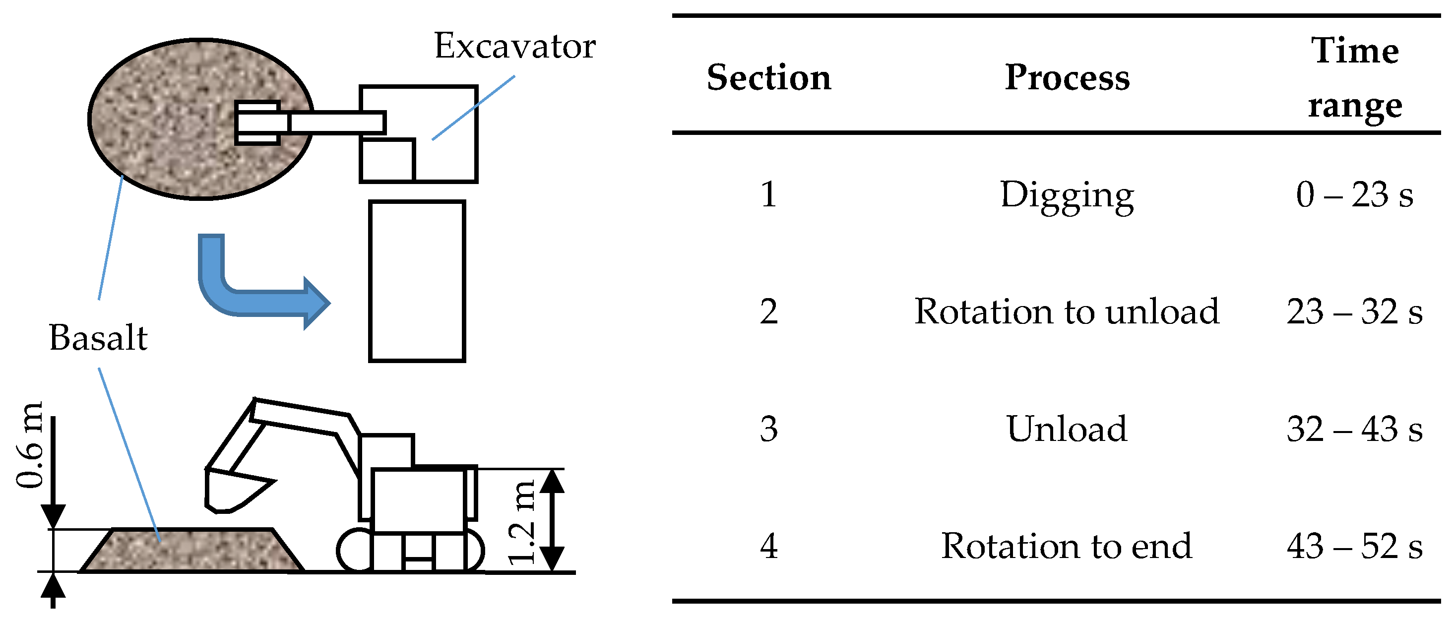
20] for determining the fuel consumption and energy losses of hydraulic excavators, for example. A 90 degree dig and dump cycle is performed as a test cycle. Dimensions and execution of the cycle are shown in
Figure 5. With nominal filling quantity of 36 L and moved basalt chips (8 to 16 mm grain size), the weight per transshipment is about 54 kg. After unloading the bucket, the upper carriage is swung back and the excavator arm is lowered into the starting position. The excavator position remains unchanged during the entire process. Tests are carried out in an air-conditioned laboratory so that the comparability of measurement results is ensured. In addition, the ambient temperature is recorded.
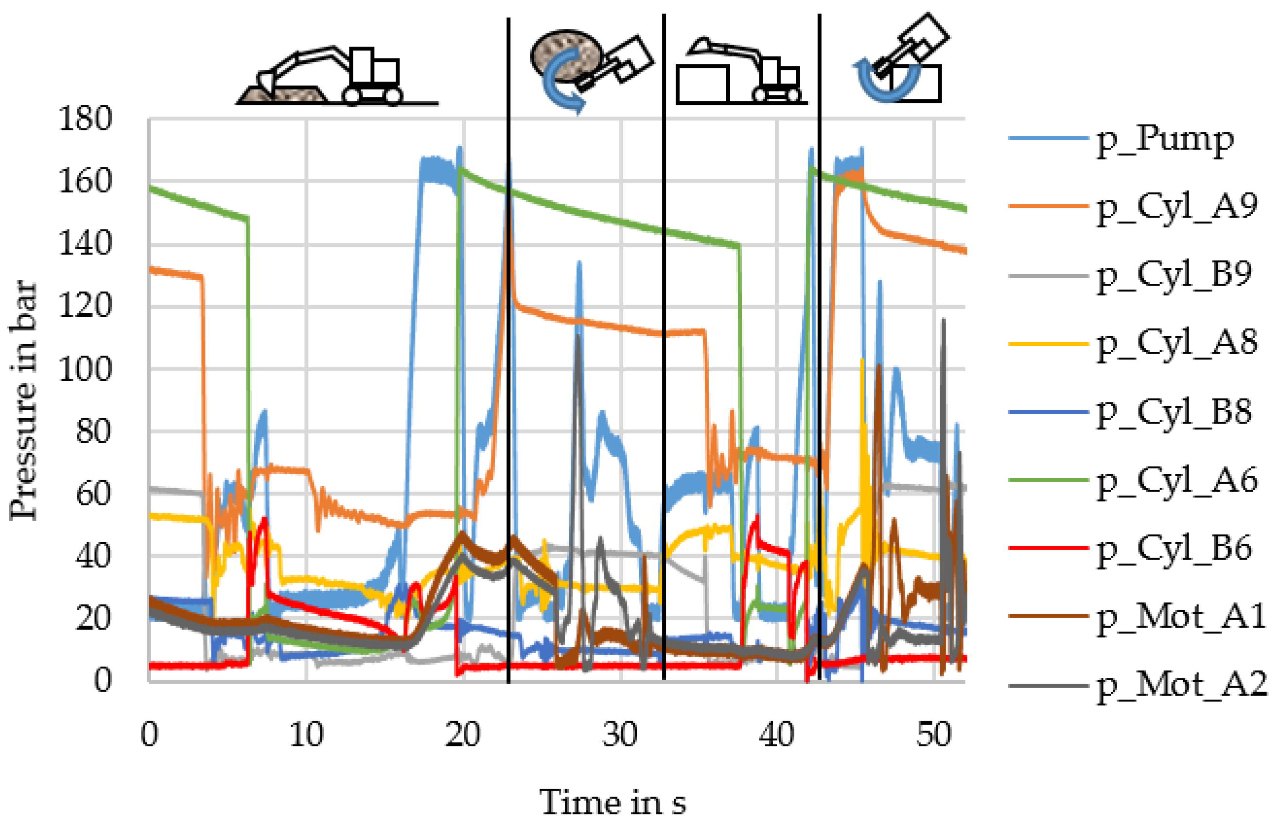
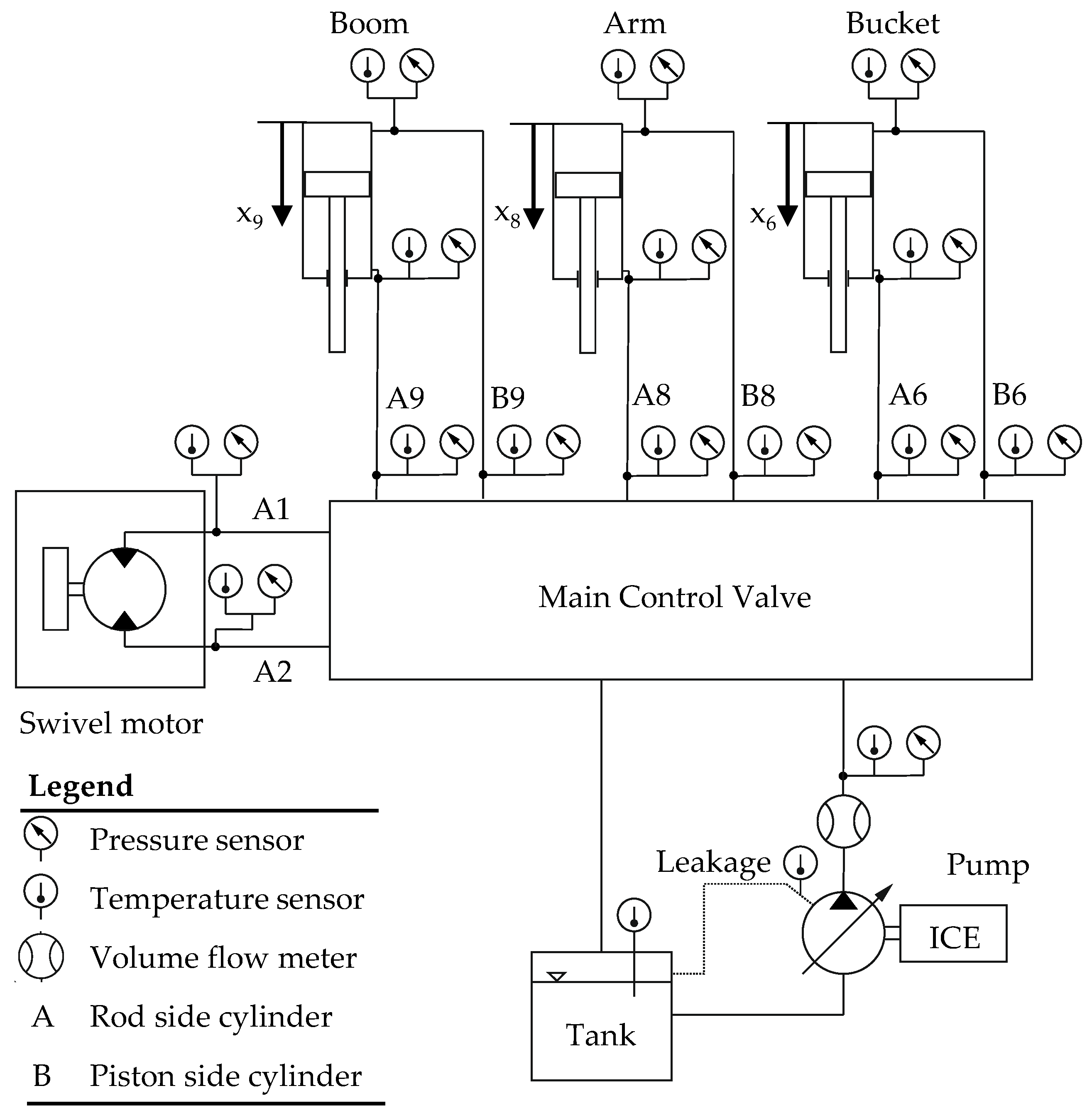
Figure 6 shows the pressure distribution during the cycle recorded at the actuators. The descriptions of the measuring points can be taken from
Figure 7. The pictograms illustrate the operations performed by the excavator during this period. Before starting swiveling at a cycle time of approximately 17 s, a rise in the pump pressure
p_Pump to a maximum of 170 bar can be seen, without a consumer requesting this pressure. This can be explained by the corresponding actuators moving at a low speed in the digging process. The variable displacement pump possesses a minimum degree of displacement and thus continues to deliver a minimum volume flow of 20 L/min, which is, however, only used to a small extent by the actuators. There is a system-dependent power loss occurs in this section of the cycle noticeable.
The high pressures of the boom (A9/B9) or bucket (A6/B6) cylinder result from holding the excavator arm’s load and the bucket loaded with grit. The load acting on the arm cylinder (A8/B8) is to a large extent absorbed by the joints of the excavator and due to this, the pressure prevailing in the boom cylinder during load holding is considerably lower. At this load, the flow to the pump is correspondingly closed by the valve spool. There is a slight oil leakage from the pressure line to the tank.
2.5. Measuring Equipment
The test excavator is equipped with appropriate measurement devices to record the relevant data. To record the measurement data, a system was set up that allows real-time measurements. For this purpose, the respective terminals for processing the sensor signals were integrated into the measurement chain. The measurement chain was then validated by means of reference measurements. The measurement data was recorded using a data logger.
Figure 7 shows the main circuit of the hydraulic system with installed sensors. The main circuit generally consists of three linear actuators: The boom, stick and bucket cylinders. The swivel motor correspondingly drives the slewing gear for swiveling the upper carriage. The diesel engine drives the main hydraulic pump. Other actuators, such as the track motor, are not considered in this study, because they were not activated during the executed test cycle.
2.5.1. Pressure
Hydraulic pressure sensors are integrated in the system to identify occurring losses. The pressure transmitters used operate in the pressure range from 0 to 400 bar and have an accuracy of 0.5%. The sensors are calibrated under connection to the entire measuring chain. The main control valve consists of several proportional valves that control the volume flow to individual actuators. The fluid is conducted to the consumers via hoses. Flow losses occur due wall friction and deflections. To record the differential pressure, the test object is equipped with pressure sensors on the piston and rod side of hydraulic cylinders.
Pressure losses that occur through control edges of the valves are measured. Due to the load sensing system design, the pump supplies the required volume flow, to hold the pressure difference on the control valve of the major activated consumer on a constant level. This results in system-related losses at other consumers due the throttling of power.
2.5.2. Temperature
Due to friction and throttling losses that occur in the hydraulic system of the excavator, energy is dissipated in form of heat. This heat is transferred to components of the system and to the hydraulic fluid, which results in a temperature increase. The fluid heating can be described by Equation (4):
The fluid of mass with heat capacity c heats up by temperature when it absorbs heat . Part of the absorbed heat is dissipated to the environment through heat conduction and convection via the hydraulic fluid, tank surfaces and hydraulic lines.
The temperature is recorded at throttling points. At these points within the system, high temperatures occur locally in the fluid, which are caused by friction. For this purpose, thermocouples are adapted into the fluid flow of the excavator’s hydraulic system.
Thermocouples of type k according to DIN EN 60584-1 are used whose measuring range according to class 1 is −40 °C to 1000 °C. According to the standard, the permissible limit deviation is 1 °C. The measurement chain was calibrated accordingly in the range of the application temperature.
The identification of the temperature enables to infer fluid viscosity, which is significant for power calculation. According to Ubbelohde-Walther the relationship between temperature and viscosity can be described by Equation (5) [
22]. The coefficent
represents the slope of the straight line in the Ubbelohde-Walther diagram. To identify the slope, two temperatures (
;
) and kinematic viscosities (
;
) of the oil are used in the equation. This formula is used to design the biohydraulic oil to the recorded minimum viscosity of the reference cycle with mineral oil. In their data sheets, the manufacturers of hydraulic oils provide information on the viscosity at 40 °C and 100 °C, from which the slope of the straight line can be deduced and the viscosity at various temperatures can subsequently be calculated. The pressure dependence is neglected in calculations due limited system pressure of 170 bar:
Furthermore, the minimum viscosity in the hydraulic system is determined. Of particular importance is the viscosity of hydraulic oil at tribological contacts of the main pump. To record the leakage oil temperature, the temperature is recorded at the leakage oil flow outlet. If the hydraulic oil viscosity falls below a critical point, the parts moving relatively to each other can no longer be sufficiently separated and thus there is no longer a lubricant film capable of bearing loads. The tribological system is thus operating in a state of mixed friction, which leads to wear of the component.
2.5.3. Volume Flow
The volume flow of actuators is recorded in order to calculate power loss occurring in the hydraulic system. The travel path of linear cylinders is recorded by means of displacement transducers. The angular position of upper carriage is recorded via a rotary encoder. The main pump’s volume flow is determined via a screw spindle counter.
2.5.4. Integration of Measurement Equipment
Figure 8 shows the practical implementation of the integration of the sensors visually. Suitable adapters are used to integrate pressure sensors and thermocouples at the identified points in the existing hydraulic system. For this purpose, these adapters are screwed in between the hose line and the consumer (cylinder/swivel motor) as well as the main valve and hose line. A pressure sensor and a thermocouple are then integrated into each of these adapters. The thermocouple is placed in such a way that the tip, which contains the elements relevant for measurement, is guided into the middle of the flow. In a slightly modified form, the sensors are placed on the main control valve.
On the hydraulic motor of the slewing gear, only sensors are placed at the connections of the motor due to the short length of the hose line. A pressure sensor and a thermocouple are also integrated in the pressure line of the main pump. Another thermocouple is inserted into the leakage line of the main pump via an elbow and measures the temperature directly at the connection of the line. In addition, the volume flow of the main pump and the fuel is recorded by means of a volume flow meter. The length of the cylinder deflection is measured by position sensors.
3. Results
In this section, the results of the experimental investigations will be regarded using a biohydraulic oil and a conventional mineral oil with respect to the test cycles, pressure and temperature distribution. Therefore, the reference cycle and investigations for selecting the biohydraulic oil are described. Finally, the results of the comparison of the excavator’s fuel consumption with mineral oil and biohydraulic oil are discussed.
3.1. Reference Cycle with Mineral Oil
The test sequence described in
Section 2.4.2. is carried out in the laboratory at the Institute for Fluid Power Drives and Systems (IFAS) of RWTH University Aachen.
The reference measurements were carried out using a mineral oil-based hydraulic fluid. This hydraulic oil corresponds to an oil of class HLP according to DIN 51524-2 [
23] of viscosity class 46.
Table 1 lists the important physical properties of the used hydraulic oil.
The tests were carried out according to the described “dig and dump” cycle. The hydraulic oil temperature rose steadily during cycles until a stationary temperature was reached. This means that the heat energy, which is transferred to the fluid through power loss, is completely dissipated into the environment. The tank temperature at start and ending of the cycle was used as an index for this. In this case, a tank temperature difference of less than 0.5 °C is measured before starting and ending of the cycle. At actuators and throttling points the temperature fluctuates by up to 15 °C. The temperatures were recorded accordingly and maximum temperatures during the cycle were identified.
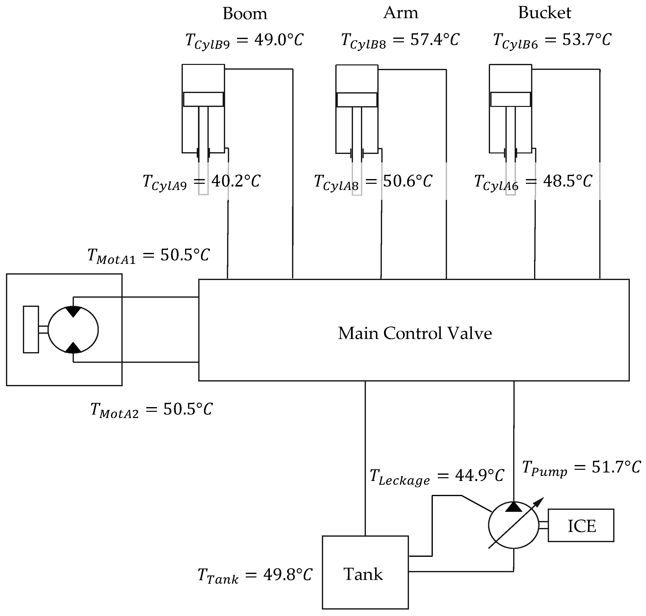
Figure 9 shows maximum recorded temperatures of respective measuring points. The maximum temperatures are independent by time of the measurement. The tank temperature in steady state is about 49.8 °C. Based on the tank temperature, a heat input of the hydraulic oil by the pump can be measured. The fluid heating due valve throttling can also be seen in increased temperature downstream of the main valve. Due to the actuation of the consumers (cylinder, slewing gear motor), a temperature increase can also be measured.
The case drain temperature is lower than the temperature downstream the pump and the tank temperature. This can be explained by the placement of the thermocouple and the system design. The tank line is permanently connected to the case drain, which means that cold hydraulic oil continuously flows into this connection. In addition, the amount of internal leakage oil is very small, which means that the change in temperature due the large volume of the tank is insignificant. Furthermore, the connection is not located in the engine compartment of the excavator like the hydraulic tank. This means that the temperature of the leakage oil is not affected by the combustion engine’s radiation. Rather, heat can be dissipated to the environment via convection at the exposed pipeline.
The maximum temperature occurs in the pipe on the piston side of the arm cylinder. This temperature is measured when the cylinder is moved back to its starting position after dumping the bulk material. Here, hydraulic oil is heated by friction of the cylinder seal due to relative speed between piston and cylinder wall in the seal’s lubrication gap.
3.2. Selection of a Biohydraulic Oil
After the test results’ evaluation, a biohydraulic oil is selected based on the measurement results obtained. For this purpose, a biohydraulic oil was specified that is optimised for conditions of the cycle carried out. The focus is on exploiting the advantageous rheological properties of biohydraulic oil compared to mineral oil. This behaviour is mainly determined by a higher viscosity index of biohydraulic oils.
The Sankey diagram in
Figure 2 shows that a large part of losses from mobile machines are caused by the control system of its hydraulic system. In this case, the control system refers to pipes, hoses and valves that conduct the fluid from the pump to the respective consumer in the hydraulic system. According to measurement results of [
15], the control system causes approximately 16.3% losses of total amount of energy provided by fuel. These losses result in a heat input into hydraulic fluid. According to the fluid temperature, the viscosity of hydraulic oil changes according to Equation (5).
For the design of the biohydraulic oil, measurements of the reference cycle were analyzed. The maximum temperature occurring during the “dig and dump” cycle was identified. For this purpose, the temperatures after warm-up, i.e., after reaching a stationary tank temperature of the test excavator, were considered.
As described above, the maximum temperature occurs in the line of the piston side of the arm cylinder. This temperature occurs when the cylinder is moved back to its starting position after unloading the bulk material. The temperature recorded amounts to 57.4 °C. Based on this temperature, the minimum viscosity in the system during the cycle is determined. Using Equation (5) the minimum oil viscosity during the cycle can be determined by applying the maximum measured temperature and viscosity values from
Table 1. The minimum viscosity is thus 22.8 mm
2/s.
According to these data, an ideal biohydraulic oil of the Hydraulic Oil Environmental Ester Synthetic (HEES) class was selected, which meets the requirements for thermal conditions during the cycle. A viscosity index of 215 was assumed, which can be achieved by biohydraulic oils of the Hydraulic Oil Environmental Triglyceride (HETG) and HEES classes [
9].
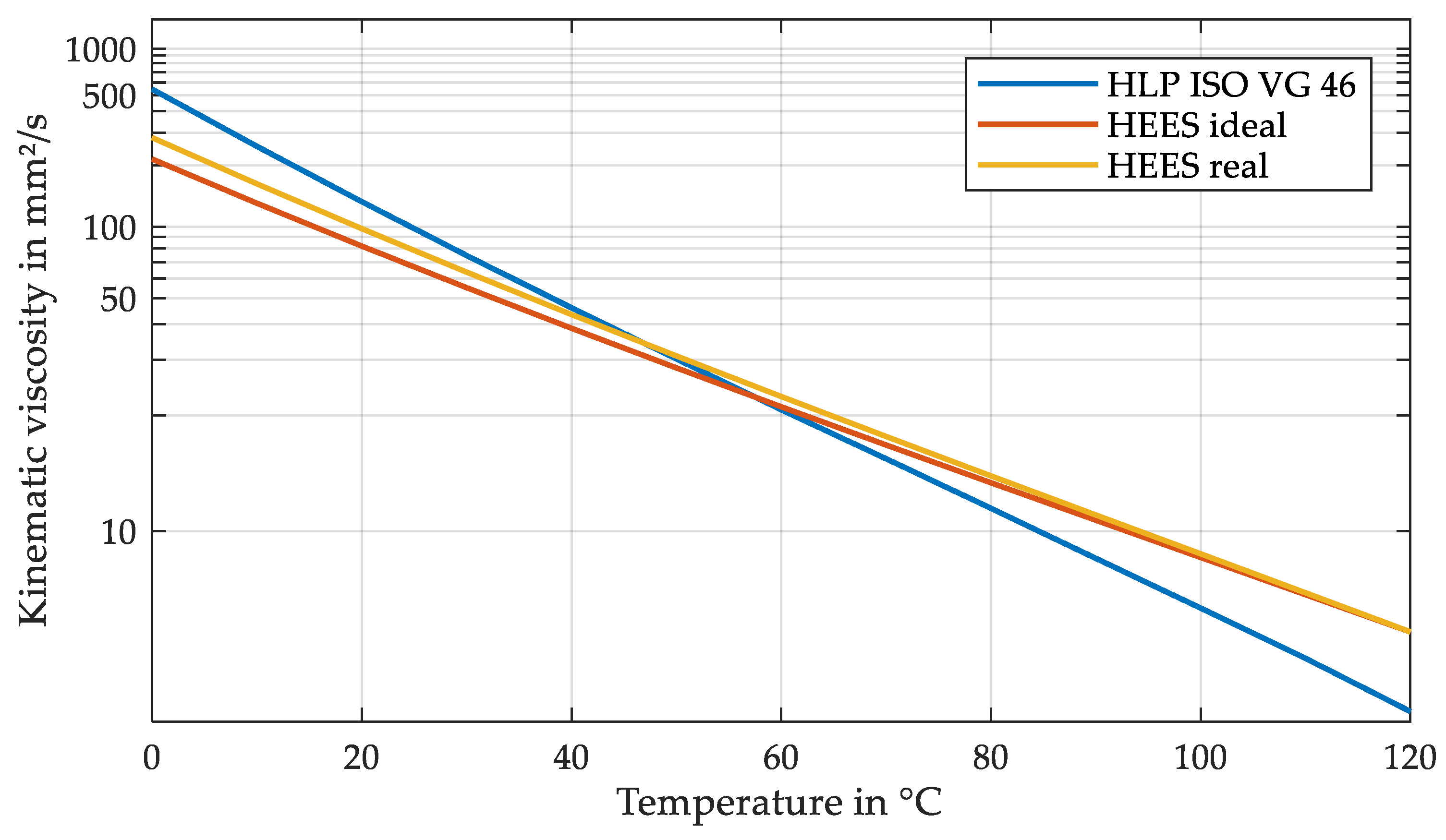
Figure 10 shows the temperature-viscosity behaviour of an ideal HEES in the Ubbelohde-Walther Diagram for the cycle carried out. Starting point is the minimum viscosity reached in the cycle. At this point, there is a corresponding intersection with HLP, since this viscosity must not fall short of during operation. Because of the biohydraulic oil’s smaller slope of the line, the viscosity is lower below the maximum temperature. This means the viscosity is even lower in the hydraulic system of the excavator, by reason of the higher viscosity index. As a result, lower hydraulic-mechanical losses are expected. At higher temperatures above the maximum temperature, the biohydraulic oil’s viscosity exceeds that of the mineral oil. This means that the operational safety of the machine is ensured at possible local peak temperatures, which cannot be measured. These temperatures include, for example, fluid temperatures in tribological contacts. The ideal biohydraulic oil has a basic viscosity of 38.6 mm
2/s at 40 °C and thus has viscosity class VG 39.
A hydraulic oil based on a synthetic ester with various additives is used in the investigations. The additivated biohydraulic oil meets minimum requirements of DIN EN 16807 [
3] in terms of biodegradability, ecotoxicity and the proportion of renewable components. Furthermore, the oil fulfils the performance requirements for HEES class according to DIN ISO 15380 [
8]. In addition, the developed biohydraulic oil has been certified for environmental compatibility according to EU Ecolabel [
25] and Blue Angel [
26].
The biohydraulic oil was selected according to the ideal progression of viscosity-temperature dependence determined in
Figure 10. A particular challenge in the development and formulation of the hydraulic oil was to determine the viscosity according to the ideal curve and to achieve a high viscosity index.
Table 2 lists physical properties of the finished biohydraulic oil. In addition to higher density of the biohydraulic oil compared to mineral oil, biohydraulic oil has a lower specific heat capacity.
The limitation of technical possibilities in the production of biohydraulic oil led to the fact that the ideal progression of the viscosity-temperature dependence could not be achieved exactly in the production of the oil. As already mentioned, the viscosity index of the developed biohydraulic oil is 192 in contrast to the ideal hydraulic oil with 215. This means a higher temperature dependence of the manufactured oil comped to the ideal oil. The viscosity index of HEES_ real is nevertheless far above the reference mineral oil (105).
At the maximum temperature of 57.4 °C in the cycle, the viscosity is 24.6 mm2/s, i.e., slightly above the determined minimum viscosity. This means that the minimum lubricant film thickness is not falling short of during machine operation. At the reference temperature of 40 °C, the developed biohydraulic oil has a value of 43.4 mm2/s and is thus in viscosity class VG 43. The intersection of HEES_real and HLP is at 51.9 °C.
After re-oiling the test excavator, the automated “dig and dump” cycle was carried out using biohydraulic oil. The boundary conditions from the reference cycle were used. The cycle was carried out to compare the energy demand at different temperatures until a constant tank temperature was reached. Test measurements were carried out on with start at ambient temperature of 23 °C.
3.3. Measurement Results
After the comparison cycle with biohydraulic oil has been carried out, the measurement results are evaluated and analysed. In the following, the comparability of measurements, temperature curve and fuel consumption of the reference measurements and the comparison measurements are discussed.
3.3.1. Comparability of the Results
The comparability of different cycles can be evaluated with different factors. On the one hand, the movement of actuators during the execution of cycles is a reference for the comparability of cycles. This comparability is given by automated control of actuators. However, vibrations can occur due to inertia of machine components. Furthermore, the machine is designed for robust operation on construction sites, which means that the used components are not necessarily designed for control in range of a few millimetres.
In order to be able to assess the extent of these interference factors, the position of the bucket tip was recorded over the cycle duration. This is calculated accordingly via cylinder lengths.
Figure 11 shows the course of the bucket tip in two different cycles. Illustrated is the comparison of two different cycles one with mineral oil-based hydraulic fluid and the other with biohydraulic oil. Both measurements were taken in the same temperature range (
). Sufficient accuracy can be achieved when comparing two cycles. The mean value of standard deviation of respective measuring points is 2.8 cm in the X-direction (horizontal) and 1.2 cm in the Z-direction (vertical). This deviation is a more than sufficient value for comparability of different cycles when considering the described interfering factors.
An important reference for comparability of measurement results is the fluid temperature. Starting from the hydraulic tank, the fluid is pumped up into the hydraulic circuit by the main pump. For this purpose, the tank’s temperature is set as a reference for comparability of cycles at different temperatures.
Figure 12 shows the course of the tank temperature during successive cycles.
It can be seen that the temperature is approaching a limit value, which is about 50 °C. The ambient temperature is constant with 23 °C for all measurements since these measurements are being carried out in an air-conditioned test laboratory. The mass of handled gravel is identical for all measurements. Moisture of the bulk material is also constant due to the air-conditioned environment.
3.3.2. Temperature Behaviour
The fluid temperature at various measuring points over the cycle time is of decisive importance for the evaluation of results. This forms the base for the viscosity of two hydraulic oils under consideration. The different viscosities at various operating points and the variation in physical properties of two hydraulic oils can cause the temperature curve of these two oils to differ.
The heating of the hydraulic fluid due to power loss is exemplified by the main pump of the hydraulic system.
Figure 13 shows temperature curves of the two hydraulic fluids at the pump outlet and the displacement volume over the cycle time. Both temperature curves were determined from test runs with ambient temperatures of 23 °C. The tank temperatures are identical at 49.8 °C.
A small disadvantageous property of esters is their lower specific heat capacity. Friction, flow and leakage losses in the hydraulic system, for example at tribological contacts, flow resistances or function-related gaps, result in power losses in the form of heat. This heat can be absorbed inefficiently by a fluid with a low specific heat capacity and higher peak temperatures occur in the system. Especially at components with high power loss, for example in a valve with high throttle losses, the temperature of the fluid rises more than with mineral oil.
The slightly stronger heating of bio-oil is recognisable. This can be explained by the lower specific heat capacity of the fluid. According to Equation (4), a low specific heat capacity results in a greater temperature difference when the same heat is absorbed.
3.3.3. Fuel Consumption
Fuel consumption is used to evaluate the energy consumption of the test excavator while performing the cycles. The energy demand of the hydraulic system can be related to a large extent to the incoming energy of the fuel into the combustion engine (cf.
Figure 2). If the power demand of the hydraulic system increases, for example due to a higher load, the combustion engine must cover the demand by providing more power.
Fuel consumption is determined by two volume flow meters. Two volumetric flow meters are necessary because the excavator uses a common rail system. Both the feed pump and the high-pressure pump must be oversized in terms of flow rate so that a rapid pressure build-up is possible both at start up and during the transition to full load. Only a proportion of the delivered high-pressure quantity is injected into the combustion chambers. For this purpose, the volume flow, which is led from the common rail back to the tank, is subtracted from the total incoming fuel volume flow . The volume flow is recorded at a frequency of 1000 Hz over the duration of the cycle. The accuracy of the volumetric flow meters is 0.001 L/min, the meters have been calibrated accordingly with connection to the entire measuring chain. The volume of fuel consumed is determined by integrating the volume flow over time.
The influence of biohydraulic oil on the fuel consumption of the test excavator is evaluated according to different tank temperatures after the cycle. Especially at low temperatures, the viscosity of the biohydraulic oil is several orders of magnitude below that of the mineral oil until the viscosity approaches the maximum temperature (cf.
Figure 9).
In
Figure 14, fuel consumption is plotted against the tank temperature of biohydraulic oil and mineral oil during respective cycles. Especially at lower temperatures (T < 45 °C), the fuel consumption of the mineral oil is higher than the biohydraulic oil. The lower viscosity of the biohydraulic oil is noticeable in this temperature range. Accordingly, the biohydraulic oil causes less hydraulic-mechanical losses (cf.
Section 2.2). Fuel consumptions converge in further course of the temperature until an intersection of fuel consumption can be seen at 46.2 °C. From this point on, the fuel consumption of the biohydraulic oil is higher than that of the mineral oil.
Table 3 shows the average fuel consumption of the two hydraulic oils considered over different temperature ranges. For this purpose, the measurement data in the temperature ranges shown were averaged. The curve shown in
Figure 14 is also recognisable in this representation. There is a small deviation of 1 mL between the temperature range of 25 to 35 °C and 35 to 45 °C for the biohydraulic oil. This behaviour can be attributed to high viscosity index of the biohydraulic oil.
After exceeding a tank temperature of 45 °C, the consumption with the biohydraulic oil exceeds that with the mineral oil. This rapid increase is difficult to attribute simply to the viscosity behaviour of the two hydraulic oils. An approach to explain the occurring processes can be made by looking at the leakage oil temperatures of the main pump.
Figure 15 shows the course of the leakage oil temperature at a tank temperature of 49.8 °C for both biohydraulic oil and mineral oil. As already described, the value of the leakage oil temperature is expected to be significantly higher. In order to determine the exact oil temperatures in tribological contacts of the pump, a complex equipment of the hydraulic pump with measuring sensors is necessary, which was not possible within the scope of this project.
When looking at the graphs, it can be seen that clear temperature peaks occur in the biohydraulic oil, which are not present in this form in mineral oil. This indicates that higher losses occur within the pump, which heat up the oil correspondingly more. This can be explained by the increase in hydraulic-mechanical as well as volumetric losses. Due to the high temperature of the biohydraulic oil in tribological contacts of the axial piston pump, a low lubricant film is generated. It can be assumed that the viscosity in the lubrication gaps falls below the minimum viscosity required to ensure a minimum lubricant film thickness, resulting in mixed friction in the tribological contacts. Furthermore, the heating of the oil leads to volumetric losses, which increase with decreasing viscosity (Equation (2)). The losses occurring in the pump have a direct effect on the fuel consumption of the pump, which can be seen in
Figure 14.
These losses provide an explanation for the rapid increase in fuel consumption of the biohydraulic oil. However, this correlation cannot be explained by viscosity behaviour of the biohydraulic oil, but can be partly attributed to lower specific heat capacity of the biohydraulic oil (cf.
Table 1 or
Table 2).
The influence of flow resistances on the increase in fuel consumption by using biohydraulic oil at higher temperatures can be excluded due to the decreasing viscosity. According to Equation (3), these losses decrease with decreasing viscosity. Previous research has shown that the influence of fluid viscosity on the parasitic losses, consisting of the flow resistances and the losses at the valve edges of the test excavator, have only a minor influence on the overall efficiency of the machine [
21].
4. Discussion
Table 3 shows the percentage savings that can be achieved by using biohydraulic oil in a crawler excavator at different operation temperatures. For operation at a tank temperature of 25–35 °C there is an average fuel saving of 26.25%, at a tank temperature of 35–45 °C a saving of 20%, compared to the operation with mineral oil. From a tank temperature of 45 °C up to temperatures of 50 °C, there is an additional fuel consumption of about 10%.
The mini crawler excavator considered in the studies is often operated for short periods on construction sites and thus the average operating temperature is below operating temperature of larger machines. Assuming an average tank temperature in range of 35–50 °C for the crawler excavator, this results in average savings of approximately 4.65%, regarding the results in
Figure 14. For this purpose, the measured fuel consumption of the two oils in this temperature range is averaged with the same rating and compared accordingly. The average fuel consumption for the biohydraulic oil is 42.53 mL per cycle and 44.61 mL for mineral oil. The temperature range (35–50 °C) was considered with regard to the standstill periods when the machine is idle. During the standstill period, the system cools down accordingly. In the case of the test excavator, at an ambient temperature of 23 °C, the tank temperature dropped from around 50 to 30–35 °C after mixing with the oil in the system after 10 min. The hydraulic oil change interval of the test excavator is 2000 h. This means that about 7590 € in fuel costs are consumed per change interval for mineral oil-based hydraulic oil, and 7237 € for biohydraulic oil at a diesel price of 1.30 €/L. This results in savings of 353 € when carrying out the described digging cycle.
This is compared to costs of filling the tank with hydraulic oil at time of the change interval. The tank capacity of the excavator is 15 L. The price for mineral oil-based hydraulic oil is currently 1.89 €/L [
24], which means that a tank filling with mineral oil costs about 28.35 €. If we assume a 6-fold price of biohydraulic oil compared to mineral oil, the price for a tank filling with mineral oil is 170.10 €. This means additional costs of 141.75 €.
In total, this results in a saving of 211.35 € for operating the excavator with biohydraulic oil compared to operating it with mineral oil when carrying out the cycle in a period of 2000 h including hydraulic oil change. In relation to the lifetime of the excavator of approximately 15,000 operating hours, this results in a total saving of 1585.13 €. Based on the construction machines purchase price of approximately 25,000 €, the savings amount to 6.34%.
The second scenario considered is a constant operation of the machine without significant breaks. This results in the tank temperature moving around a value of 49.8 °C (
Figure 12). When the machine is running continuously, the heat dissipation of the oil is lower due to the shorter residence time of the oil in the tank. In this case, the arithmetic mean of the measured data of fuel consumption during the cycle recorded in
Figure 14 is 48.6 mL for biohydraulic oil and 43.69 mL for mineral oil. This means an additional fuel consumption of 10.27% in this temperature range when using biohydraulic oil compared to conventional mineral oil. Using the previous calculation of fuel costs, this results in additional costs of 842.4 € when using biohydraulic oil during one hydraulic oil change interval. This results in additional costs, including the additional cost of the biohydraulic oil of 7381.13 € during the machine’s lifetime.
5. Conclusions
Using bio-based hydraulic oils can significantly minimize environmental risks and form a cornerstone for sustainable mobile hydraulic applications. Especially in environmentally sensitive areas, pollution can be reduced by substituting mineral oils with biohydraulic oils. In the future, increased use of bio-based hydraulic fluids will be necessary to promote the sustainability of hydraulics industry in the long term. The performance characteristics of biohydraulic oils are largely equal to those of mineral oils. The market for bio-based hydraulic fluids continues to show great potential. Potential conflicts of interest in the use of biohydraulic oils can arise in the production of the oils and the origin of the biogenic base oils. This applies in particular to products from non-certified palm oil plantations.
Current research and development is aimed at developing new concepts to increase the efficiency of mobile machines. Despite innovative developments in system design and intelligent controls, a significant portion of energy entering the hydraulic system is dissipated. A proportion of losses are due to volumetric and hydraulic mechanical losses. These losses depend, in part, on the viscosity of the hydraulic fluid used. In this article, the influence of viscosity-dependent losses of a crawler excavator is considered. For this purpose, fuel consumption is compared when using biohydraulic oil and mineral oil at different tank temperatures.
The study shows that by operating at low to moderate tank temperatures, the efficiency of biohydraulic oils is above the efficiency of mineral oils due to higher viscosity index. In the range of 35 to 50 °C, an average fuel saving of 4.65% can be achieved during the dig and dump cycle. When considering the savings to be achieved through operation with biohydraulic oil, 6.34% can be saved in relation to the purchase price of the machine, including the additional costs of the biohydraulic oil.
At higher tank temperatures, the exact opposite is shown. This is the case, for example, if the machine is used intensively for several hours. From a tank temperature of 46.2 °C, the fuel consumption when using biohydraulic oil is significantly higher than when using mineral oil.
The research was carried out under constant ambient temperatures to ensure comparability of the results between the different cycles. Various ambient temperatures favor or reduce the heat dissipation of the hydraulic system and lead to different fluid and thus fuel consumption.
As a perspective for further scientific research with regard to biohydraulic oils and their performance in mobile machinery, correlations between thermal properties and efficiency of hydraulic systems and components need to be investigated. In particular, investigations into the thermal behavior of biohydraulic oils under real operating conditions of hydraulic displacement units in mobile machines represent an important and interesting field for further research.
All in all, a rethink towards the substitution of conventional mineral oil-based oils with biohydraulic oils is necessary to make hydraulic systems independent from fossil resources. The research field of biohydraulic oils continues to offer interesting perspectives on the performance of new types of mineral oil free hydraulic fluids.


