
Cooperative Multi-UAV Conflict Avoidance Planning in a Complex Urban Environment


Abstract
1. Introduction
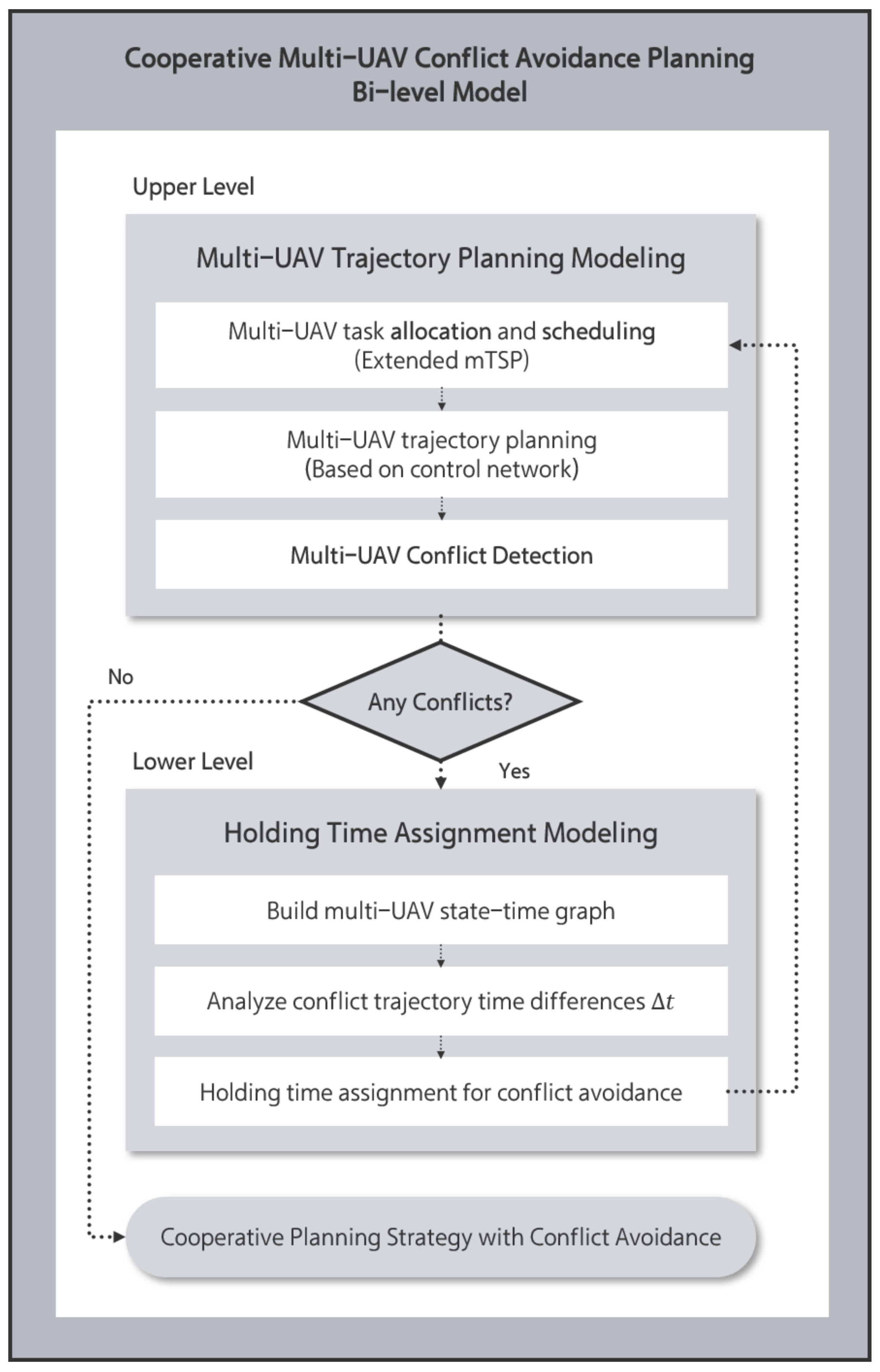
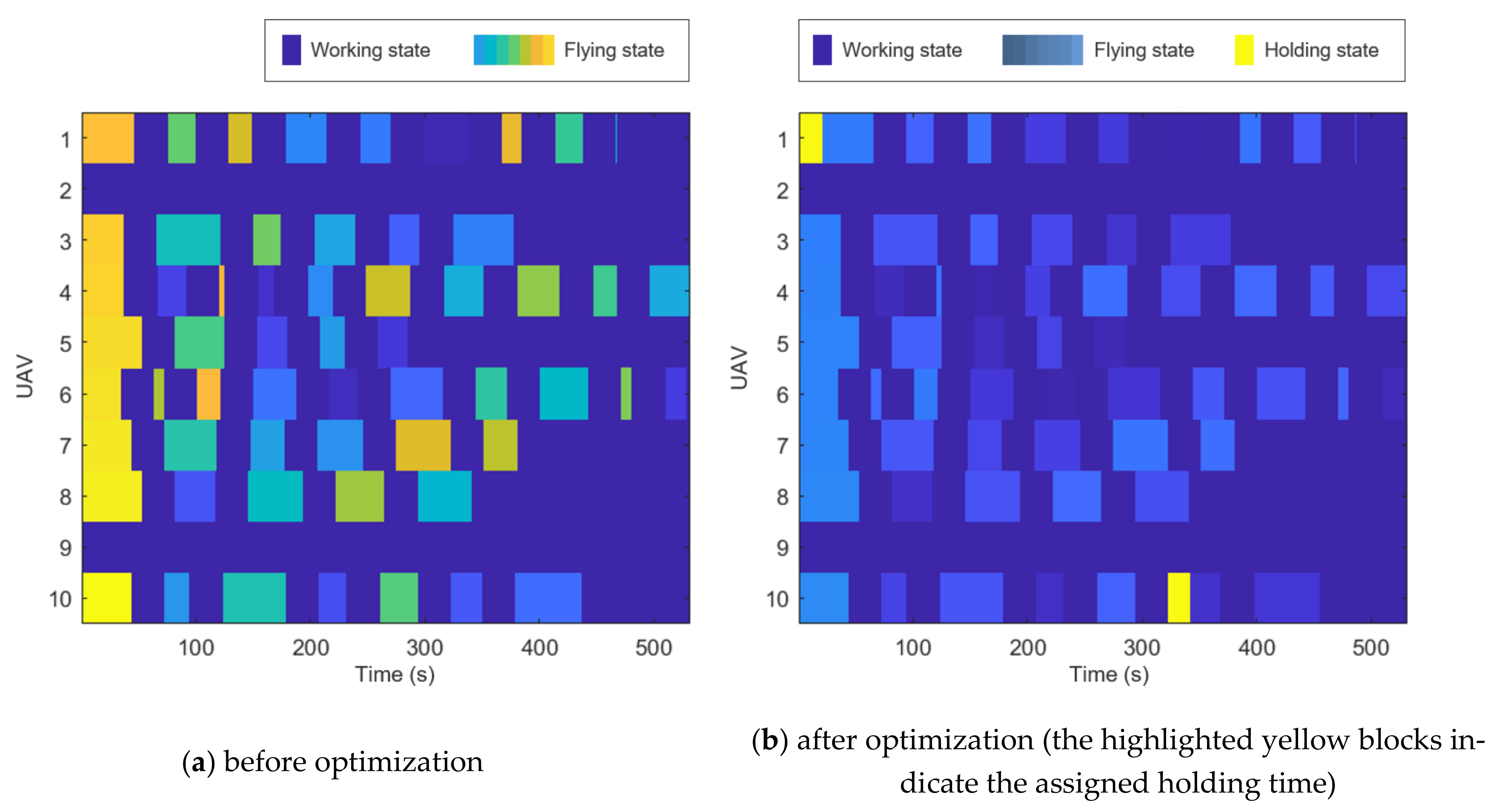
- This paper proposed a bilevel model for the MCTP problem. The upper level optimizes the task allocation and sequencing. The lower level solves the holding time assignment problem, thereby constructing a conflict-free multi-UAV system operation strategy.
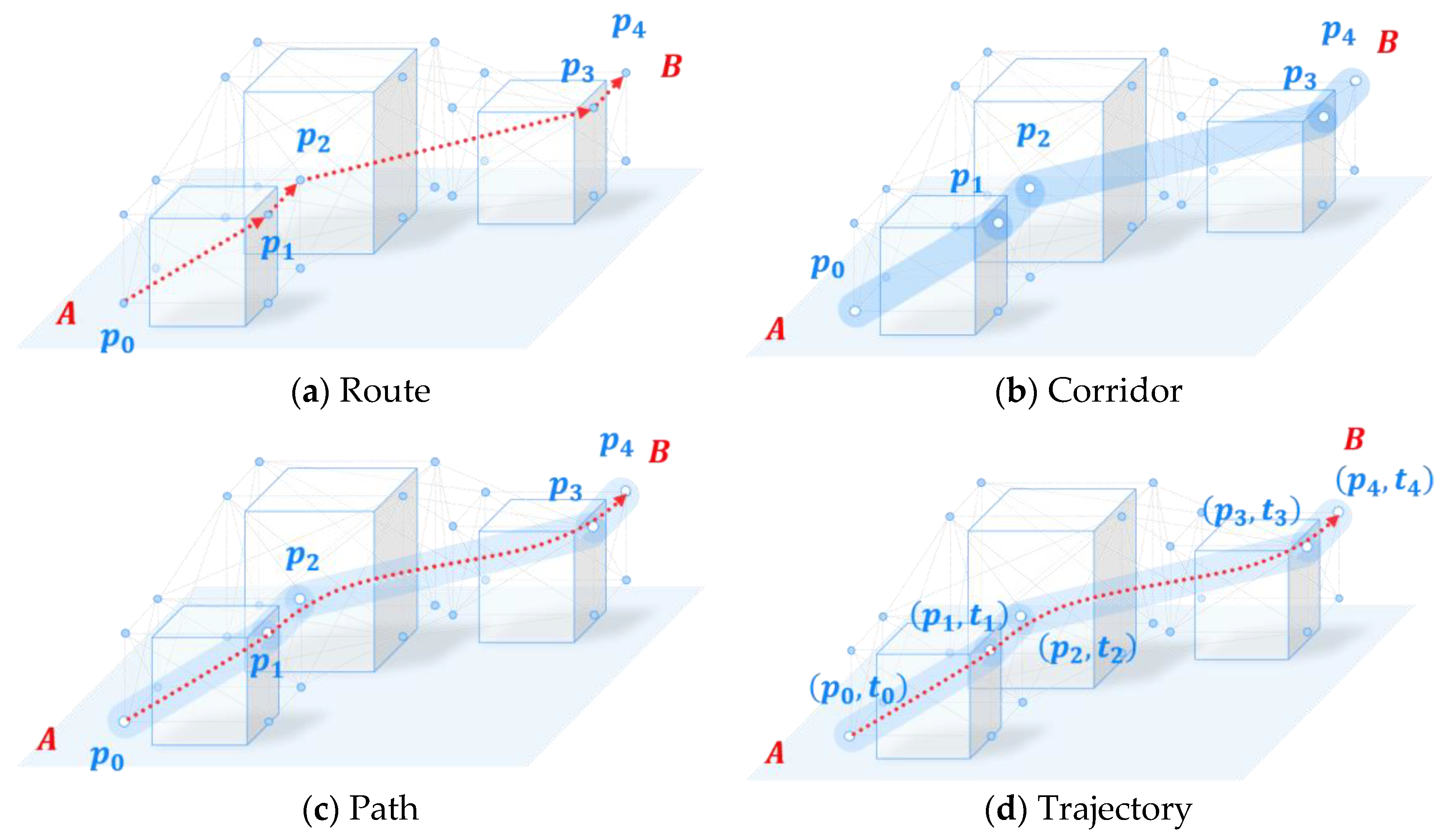
- By extending prior work on the efficient control network approach [14], practically applicable time-optimal trajectories are generated based on an optimized task visiting route plan in an upper-level model.
- A state-time graph method for conflict detection is proposed in the lower level for holding time assignment.
- Numerical experiment are discussed in both a 1 virtual city and 12 real city. An optimized system operational strategy is discussed for conflict-free automated multi-UAV services in a complex urban environment.
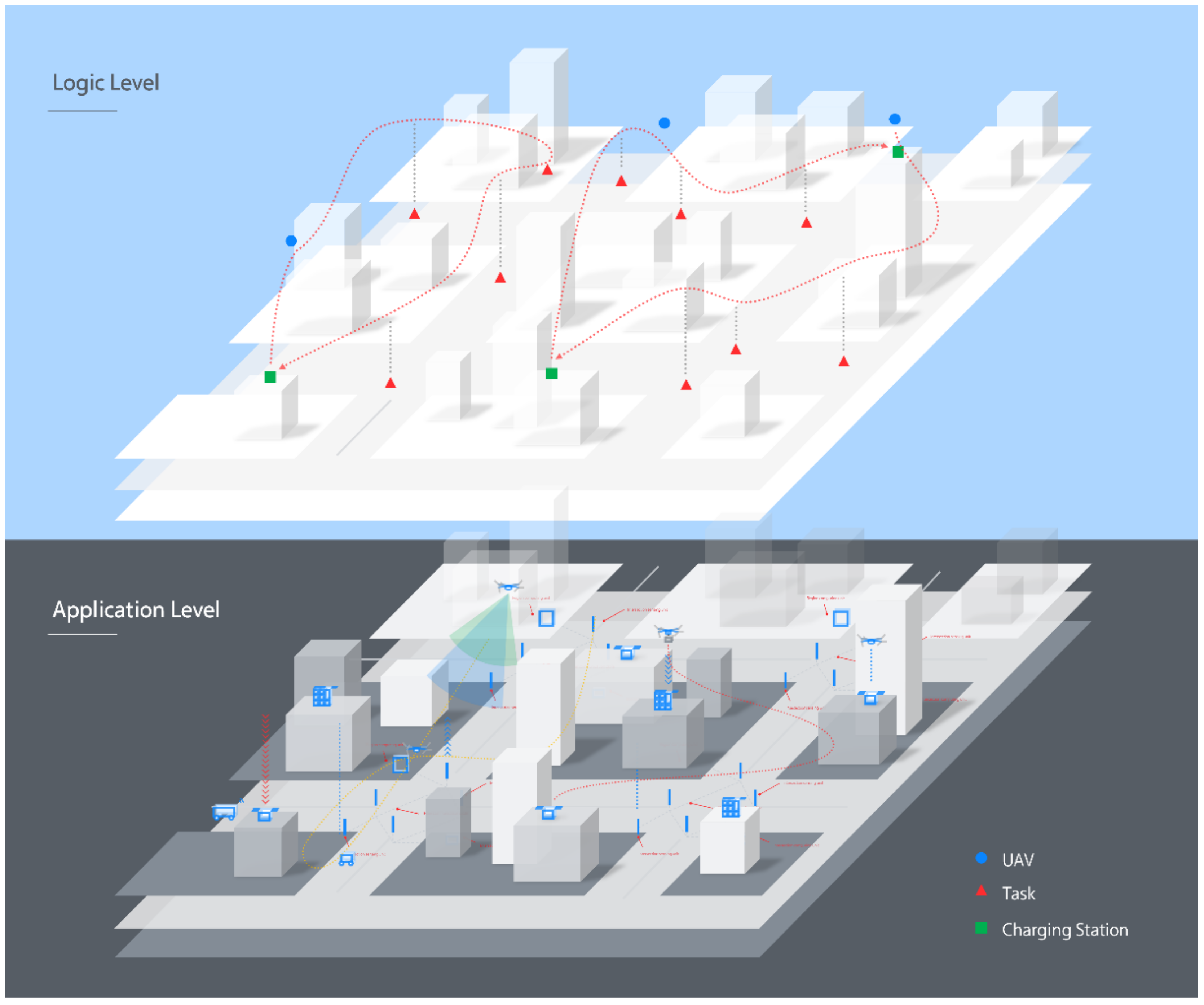
2. Problem Statement
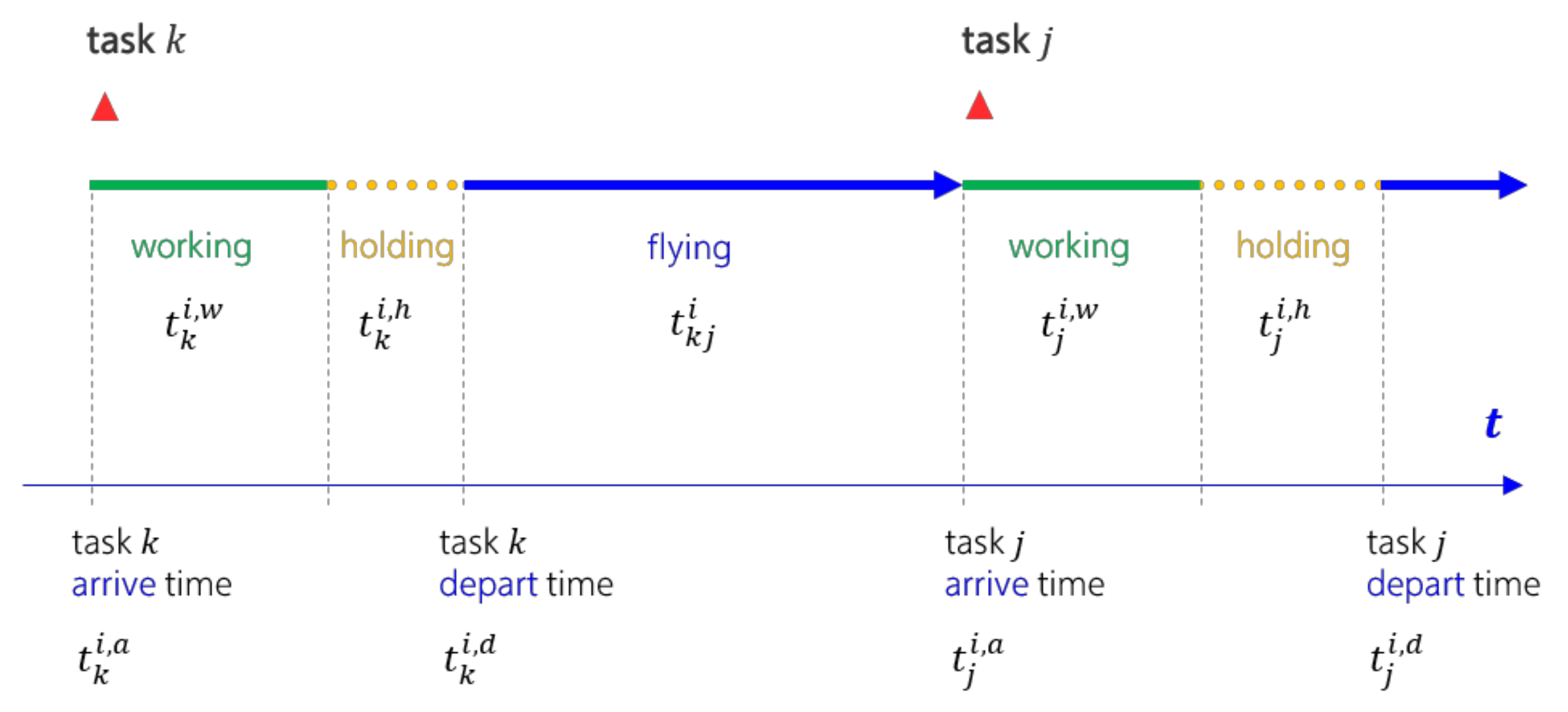
2.1. UAV State Definition
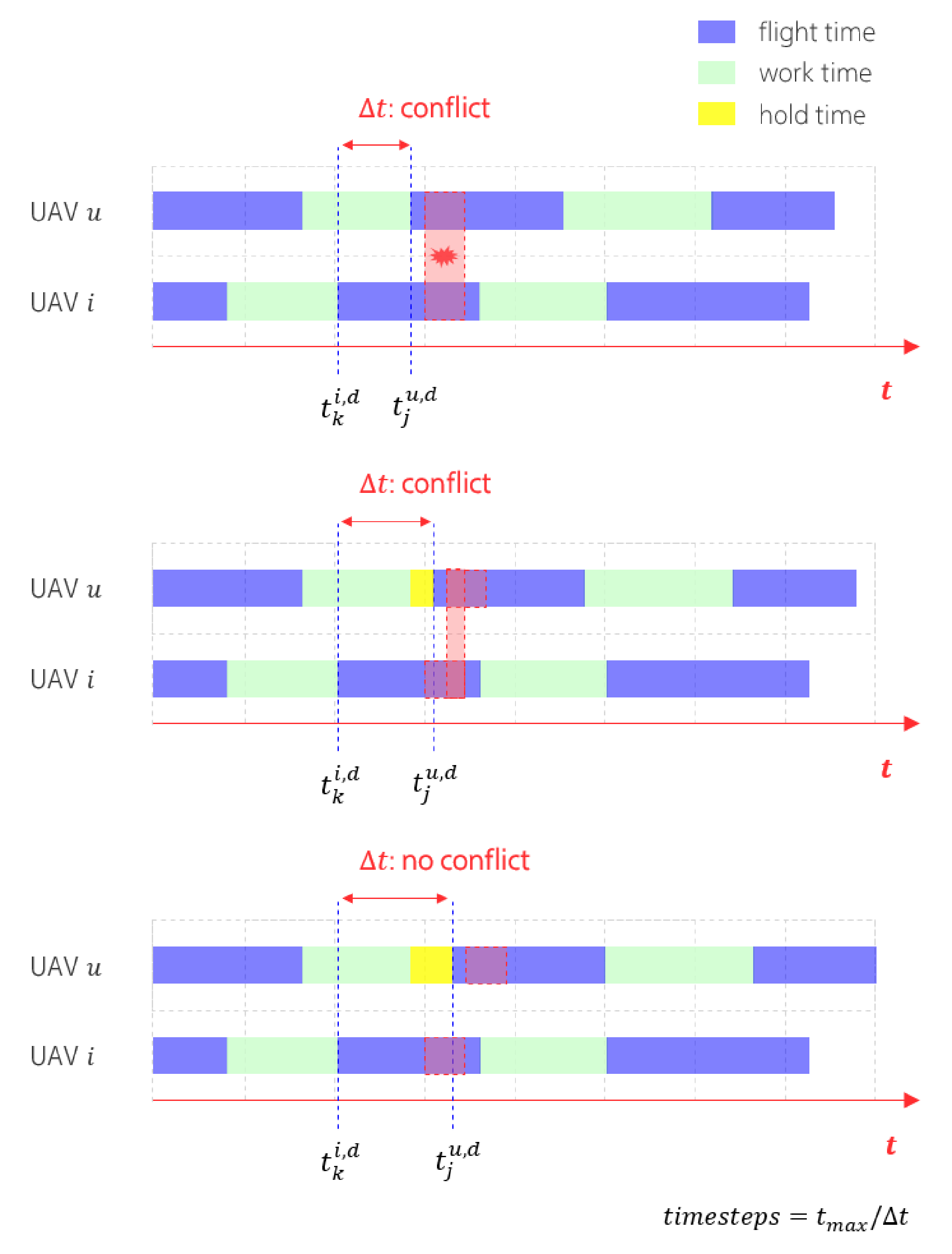
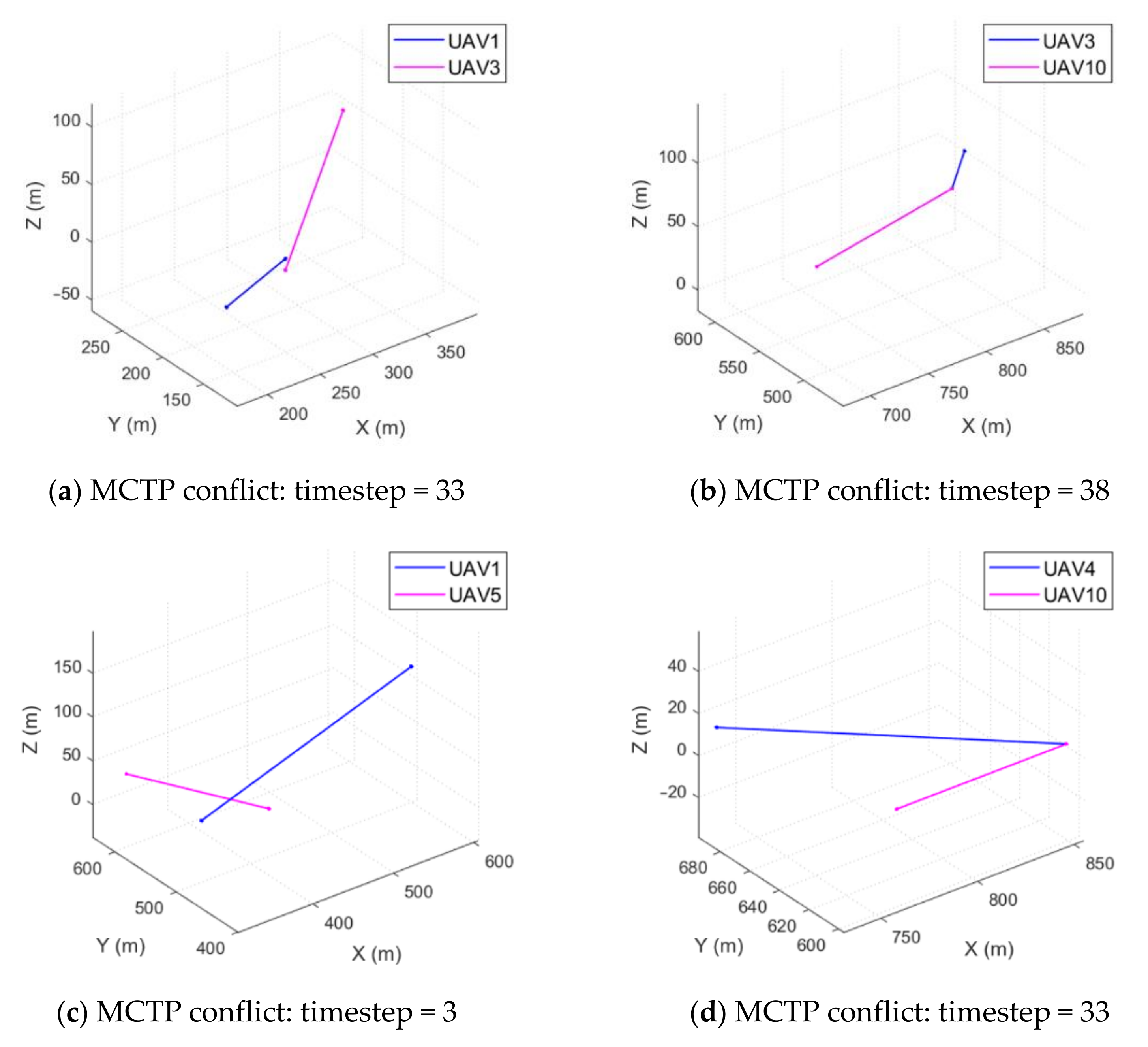
2.2. Conflict Definition
- (a)
- No two UAVs are on the same task waypoint at the same timestep.
- (b)
- No two UAVs are too close (within a Euclidean distance threshold in 3D space) while moving along the path at the same timestep.
3. Methodology
3.1. Control-Network-Based Trajectory Planning
3.2. Multi-UAV Cooperative Trajectory Planning
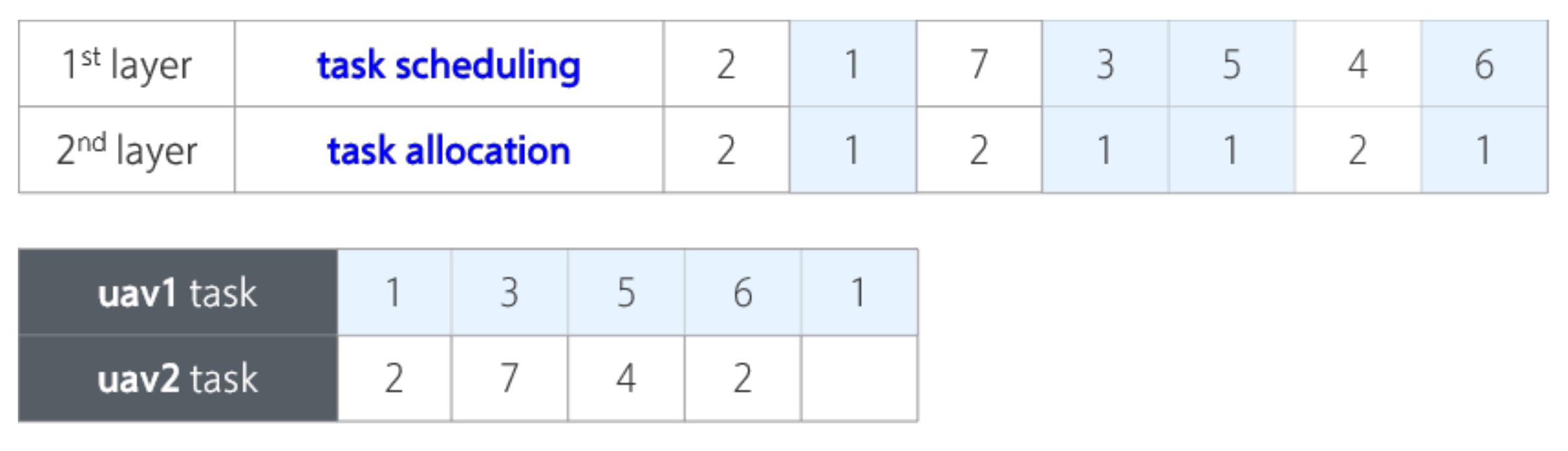
3.2.1. Upper Level: Multi-UAV Trajectory Planning (MTP) Modeling
3.2.2. Lower Level: Holding Time Assignment Modeling
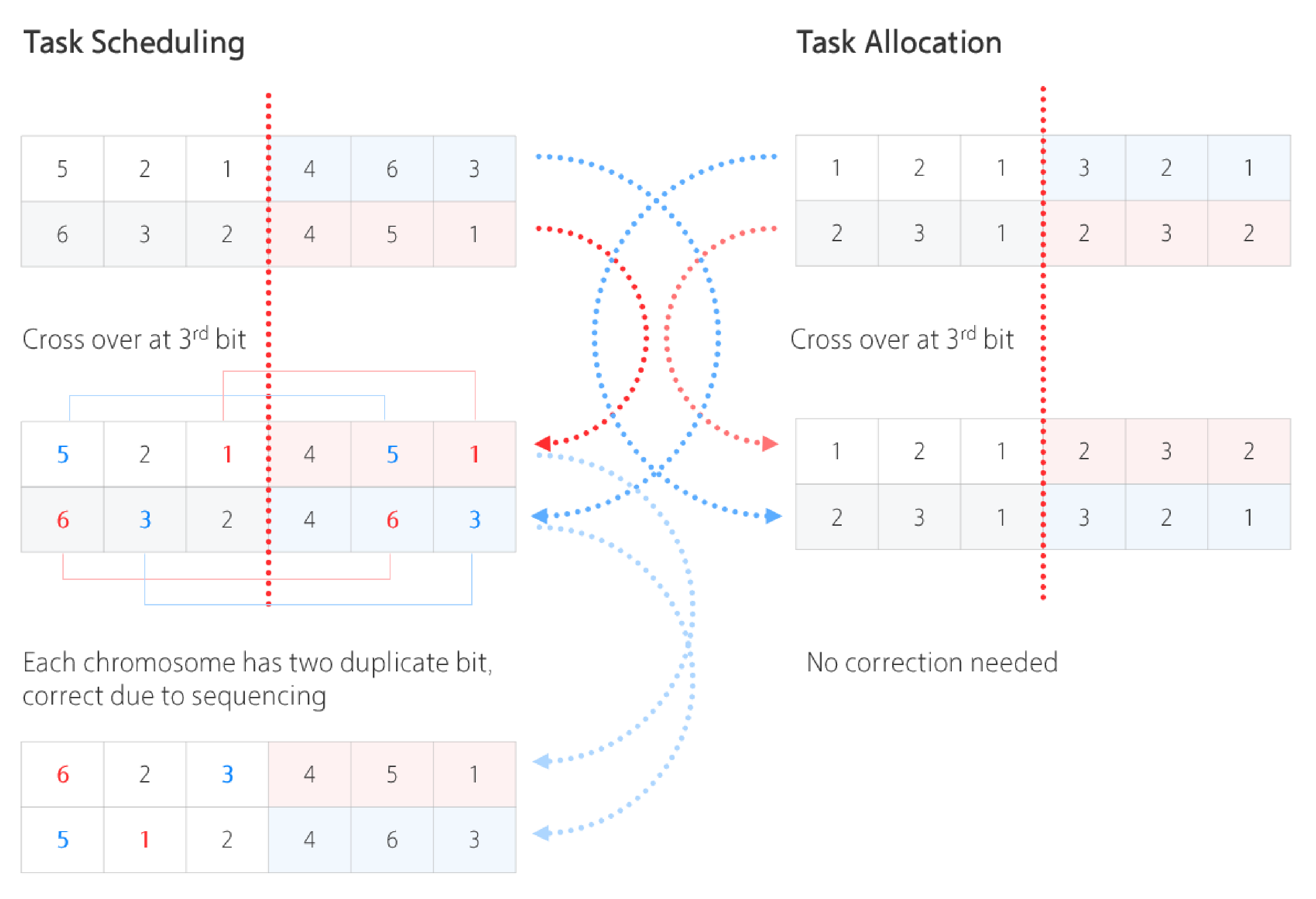
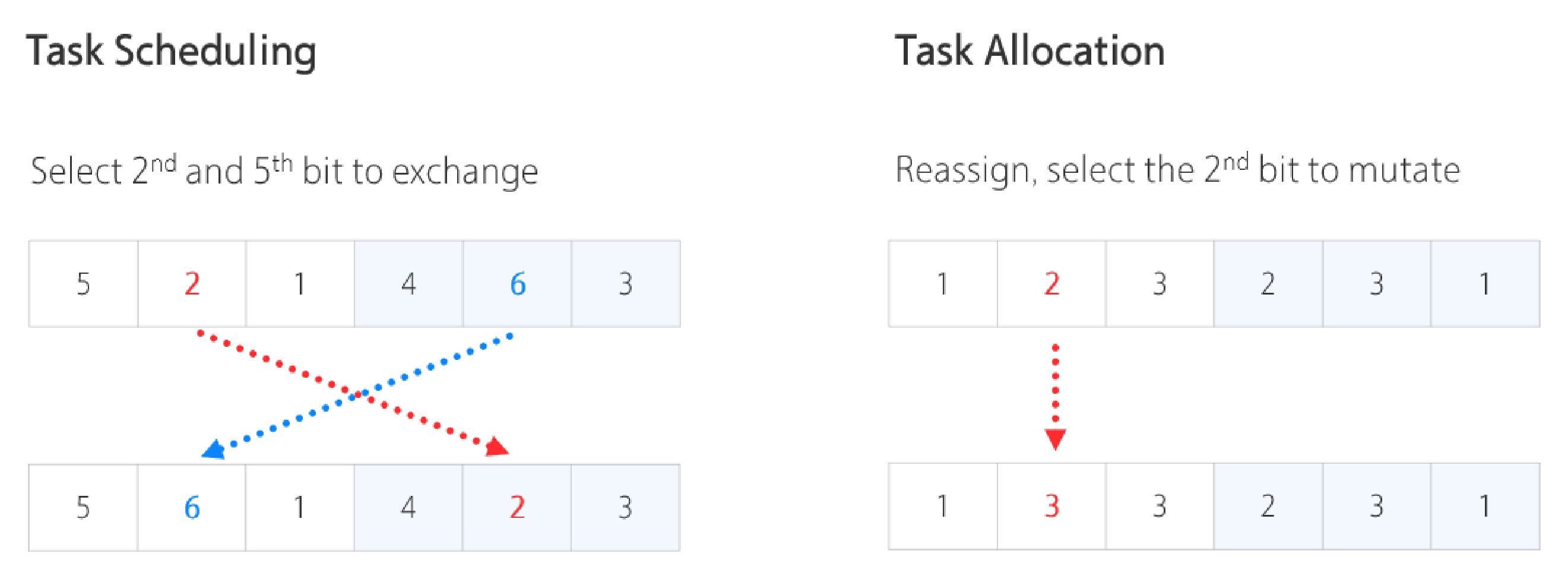
3.3. Solution Approaches to MCTP
3.3.1. Heuristic Framework
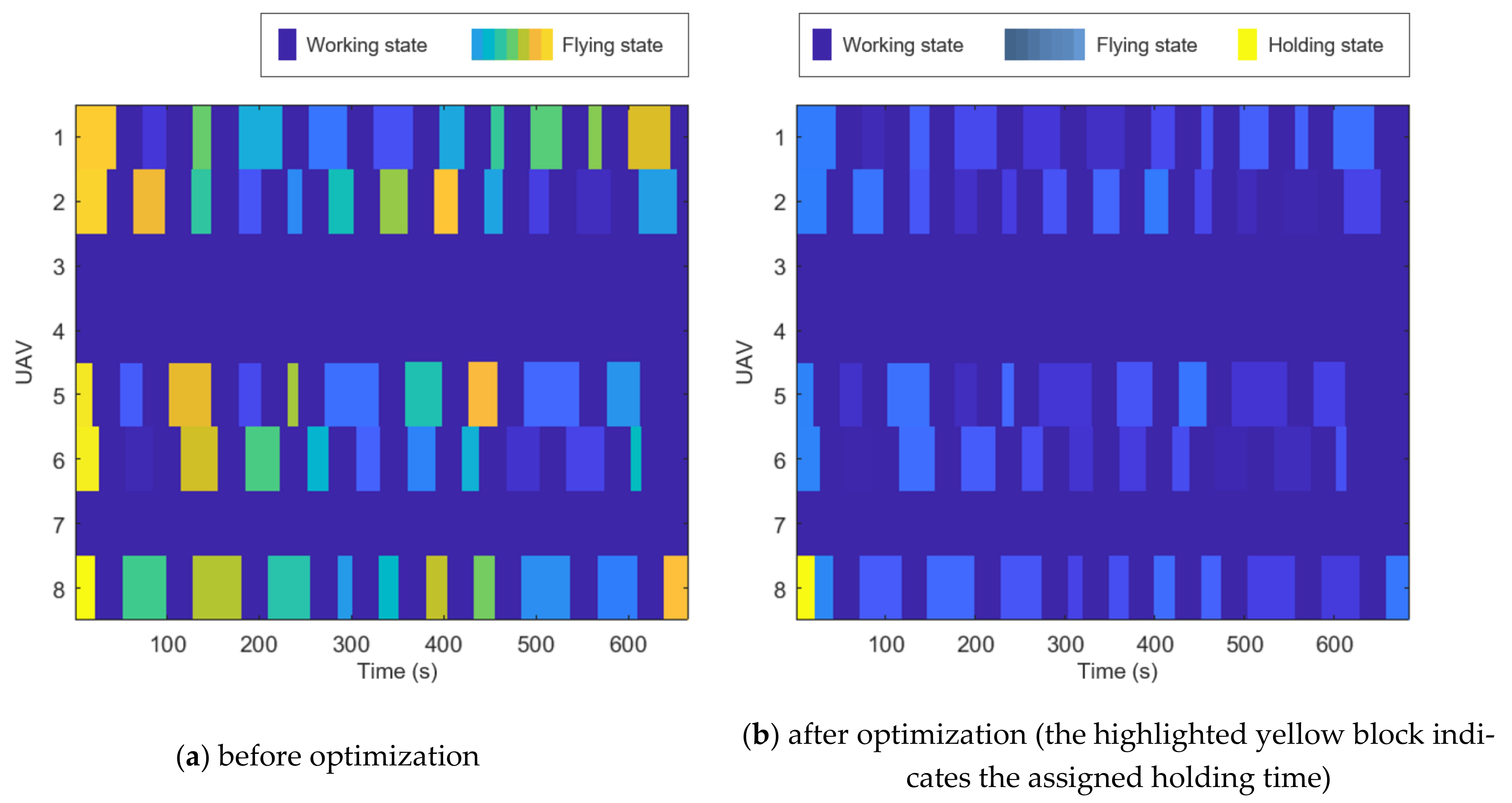
3.3.2. Holding Time Assignment Problem
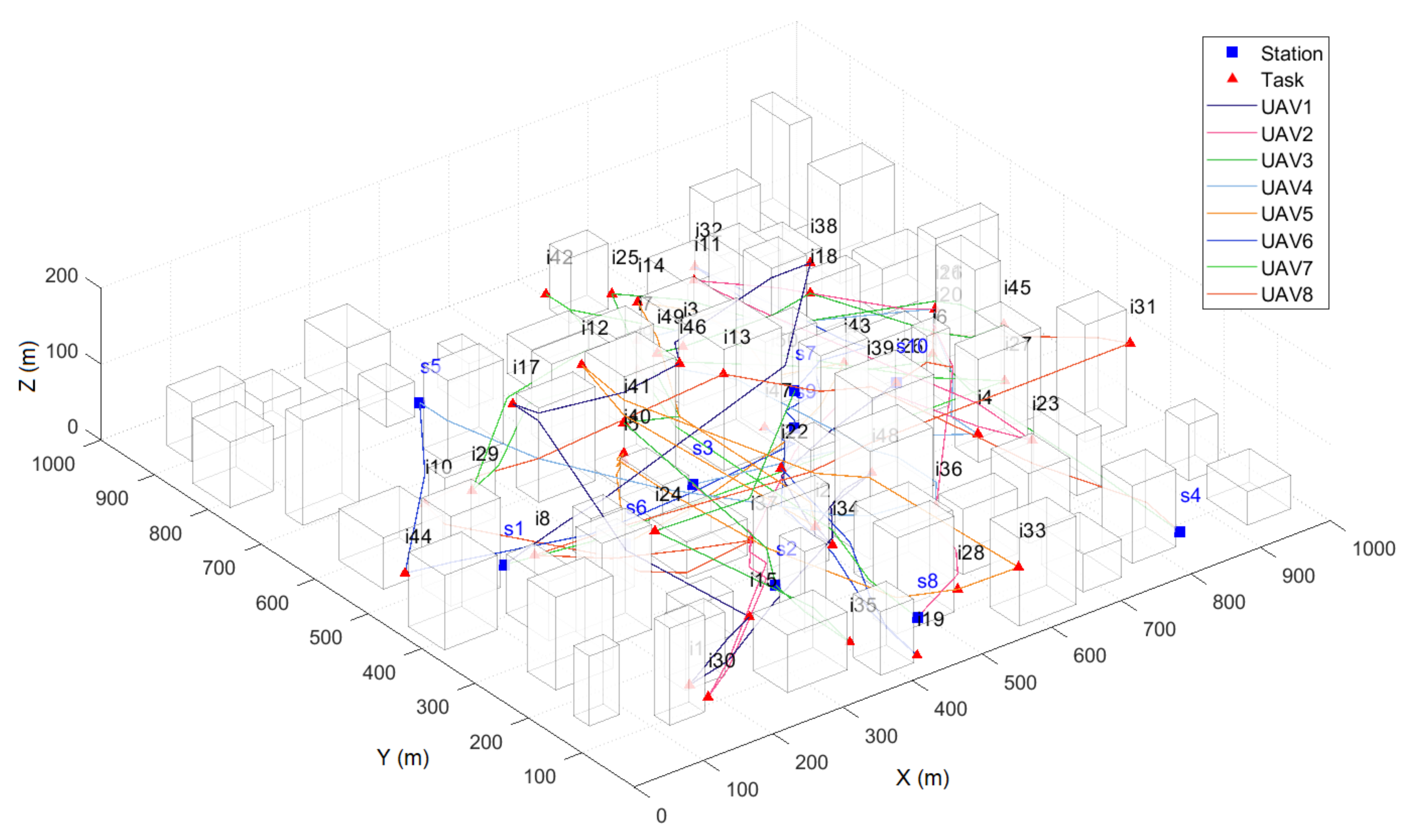
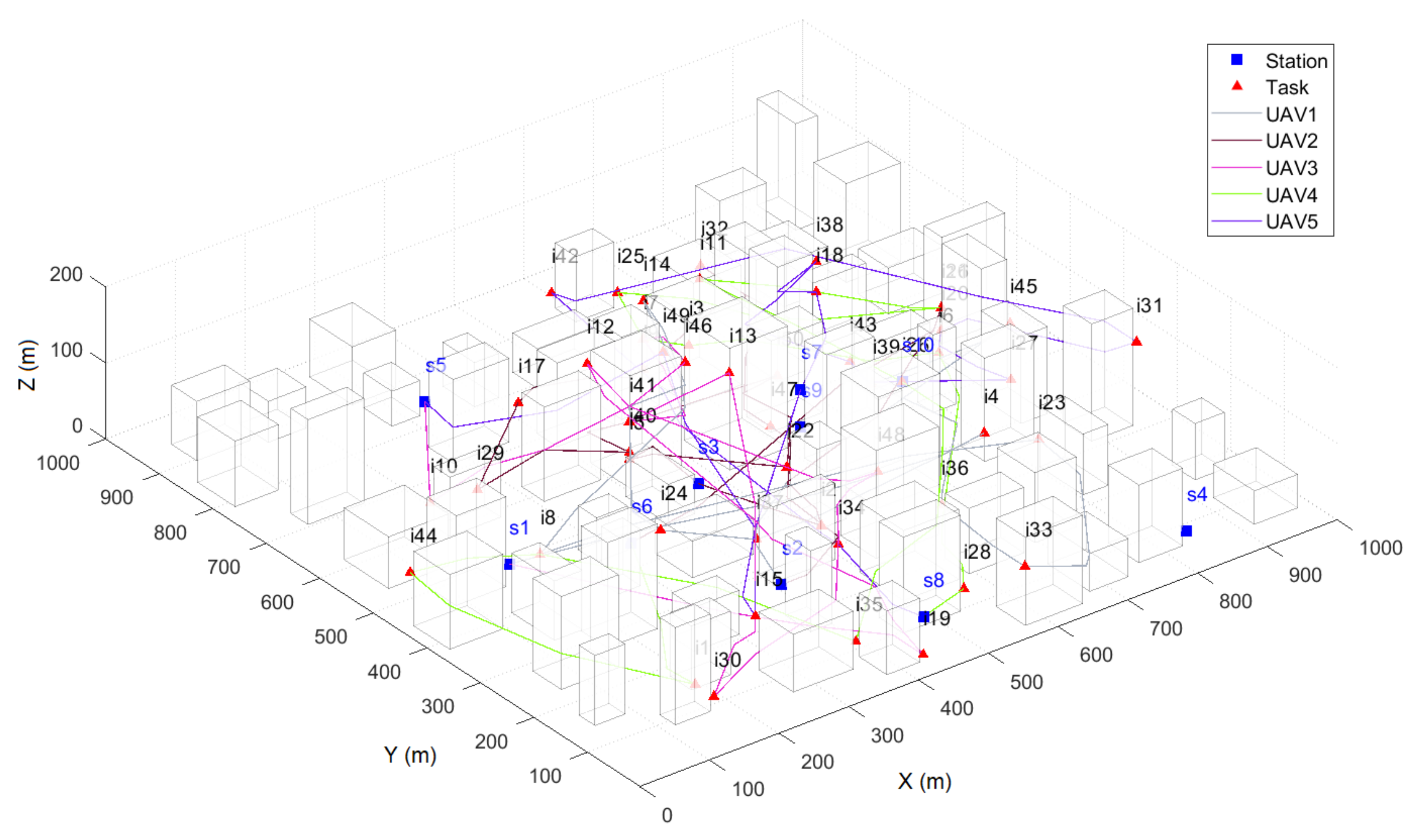
4. Numerical Study
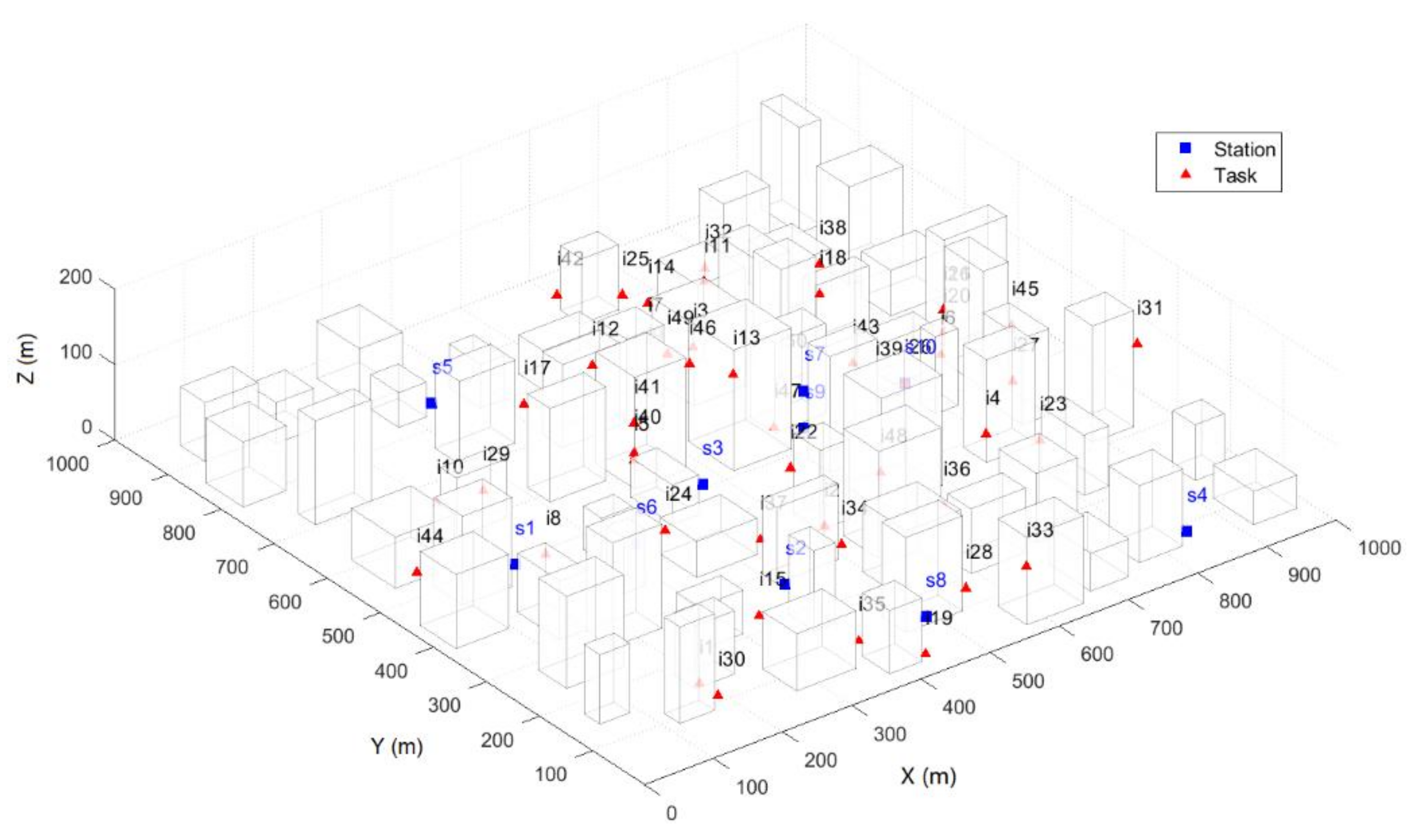
4.1. Experiment Setup
4.1.1. Virtual City
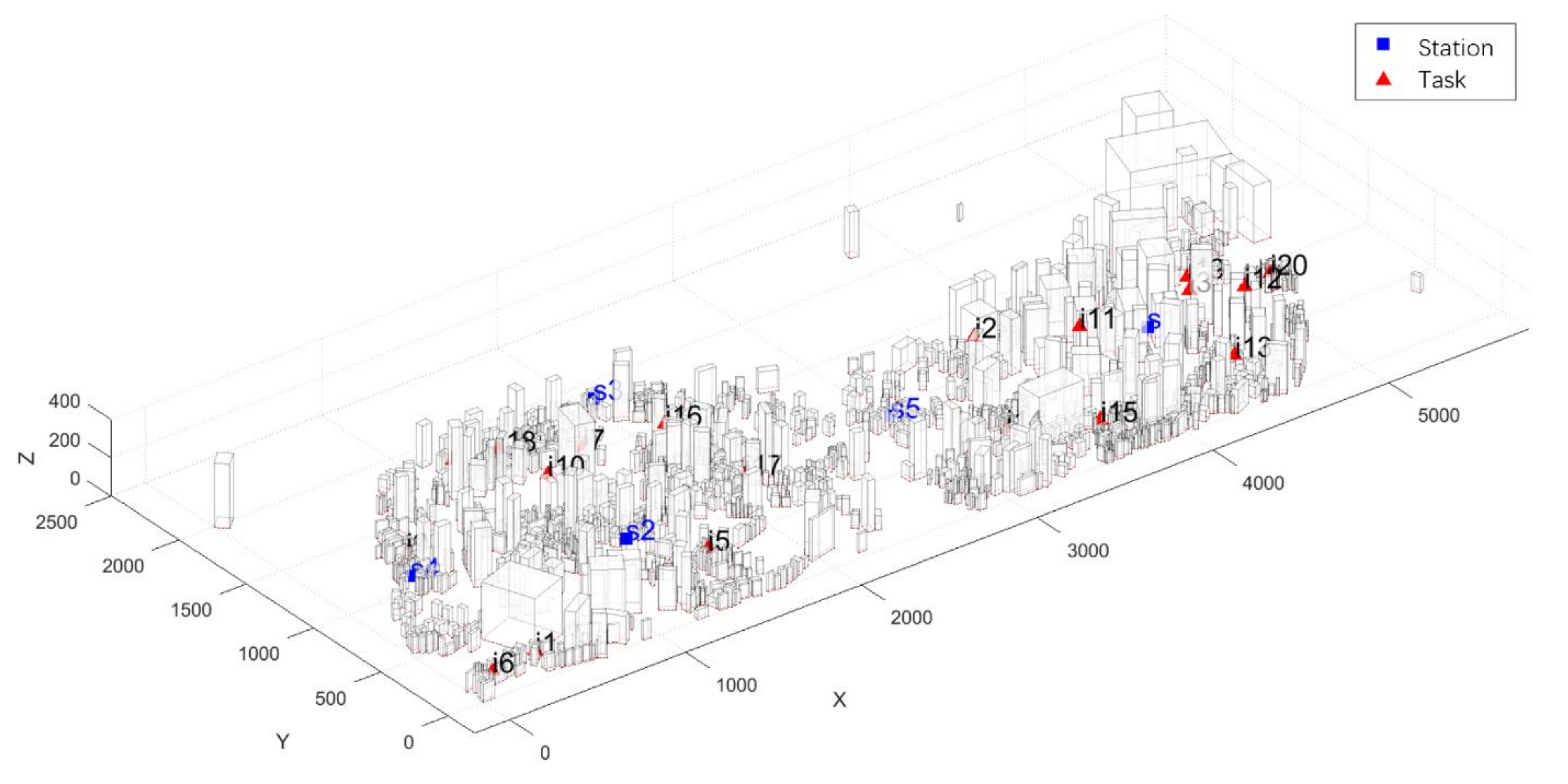
4.1.2. Real City
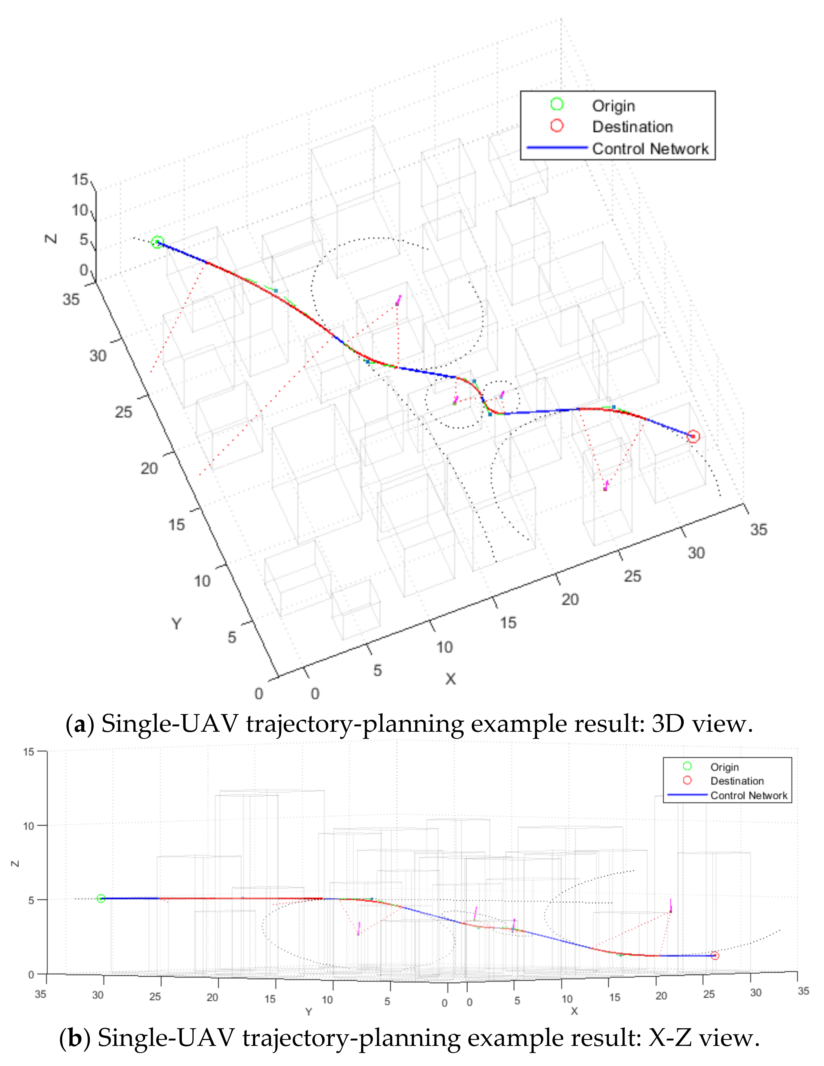
4.2. Virtual City MCTP Results and Discussion
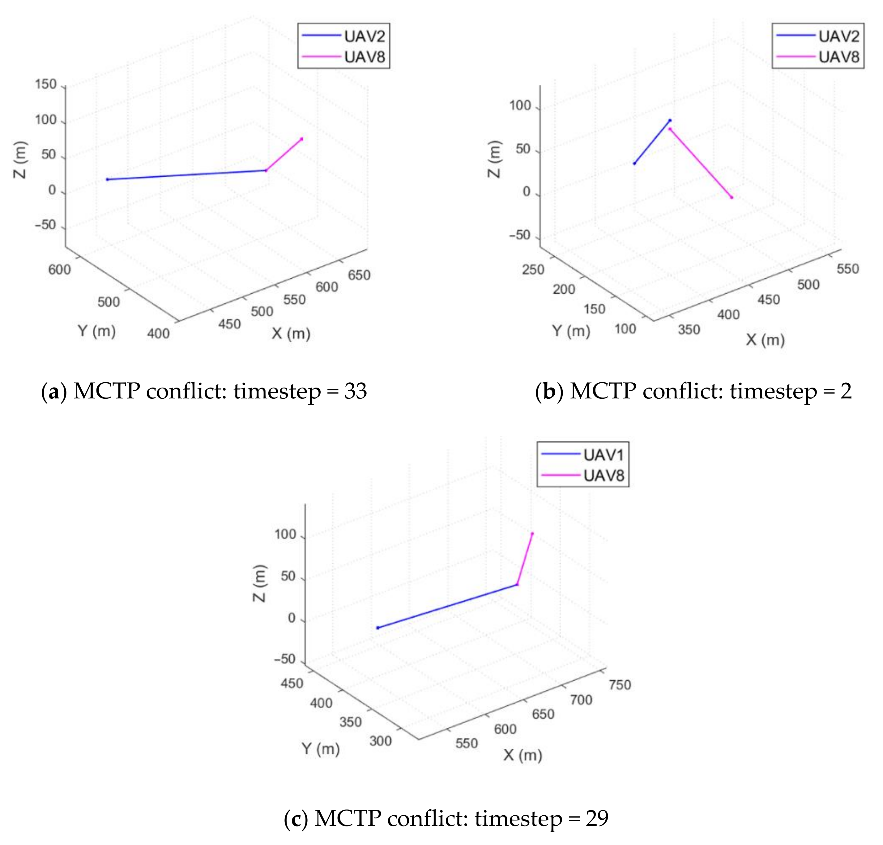
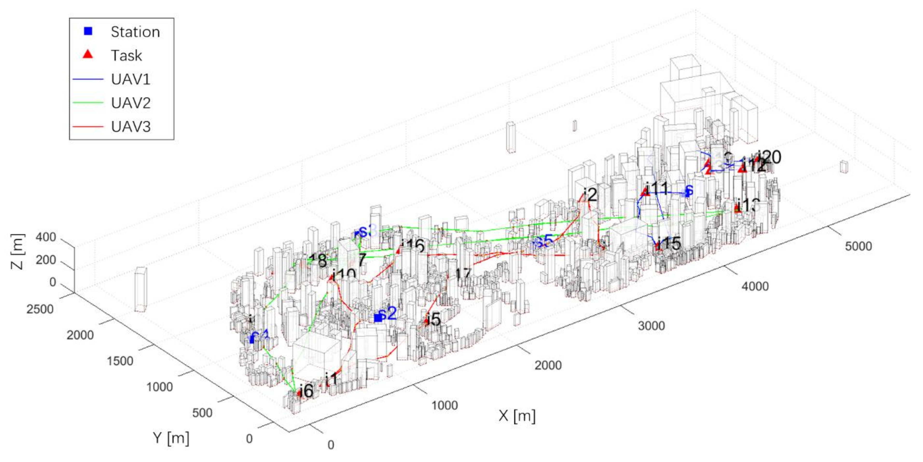
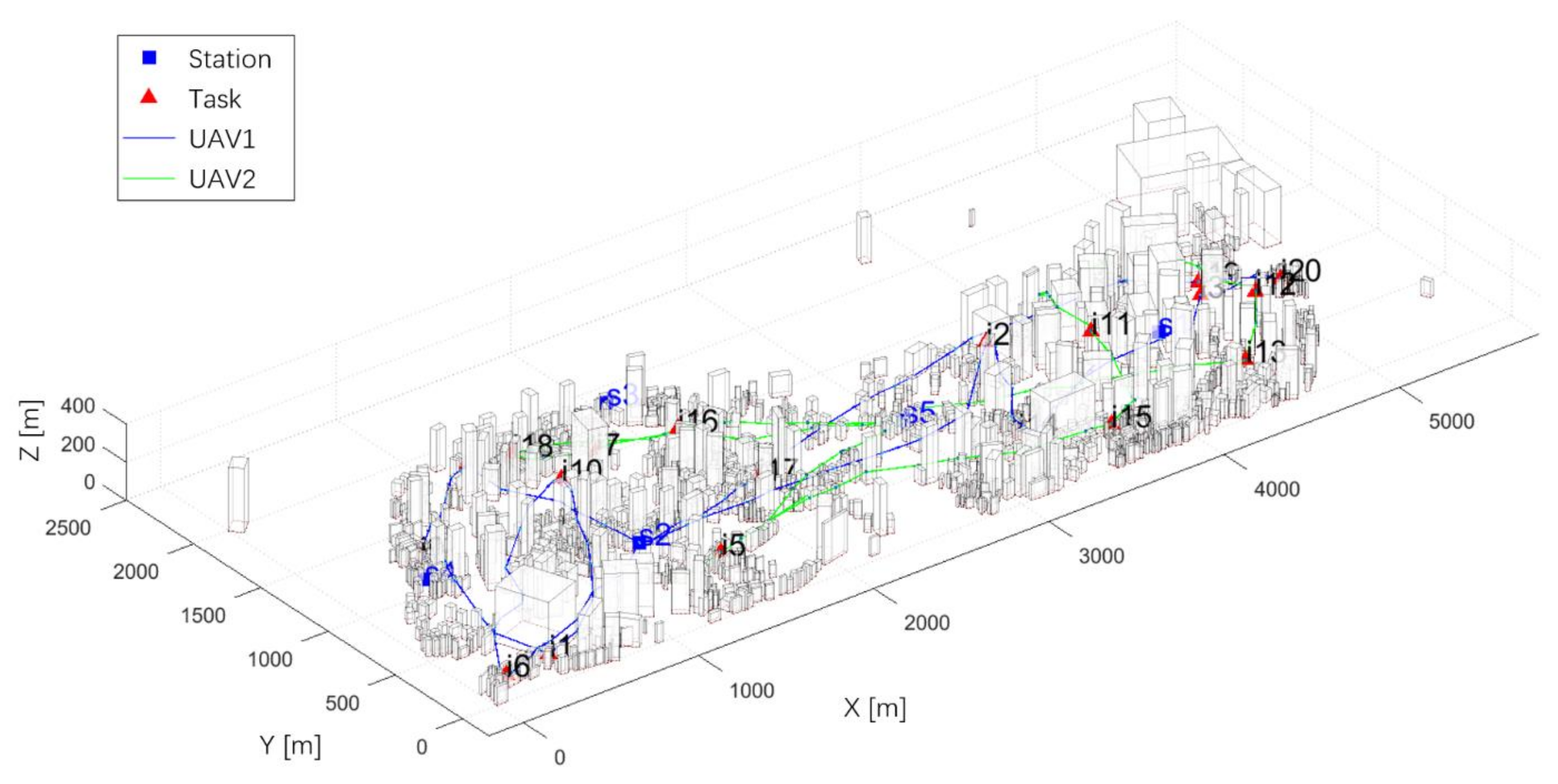
4.2.1. Case 1 with Eight UAVs
4.2.2. Case 2 with Five UAVs
4.2.3. Comparison between Case 1 and Case 2
4.3. Real City MCTP Results and Discussion
5. Conclusions
Author Contributions
Funding
Institutional Review Board Statement
Informed Consent Statement
Acknowledgments
Conflicts of Interest
References
- Liu, M.; Liu, X.; Zhu, M.; Zheng, F. Stochastic drone fleet deployment and planning problem considering multiple-type delivery service. Sustainability 2019, 11, 3871. [Google Scholar] [CrossRef]
- Eun, J.; Song, B.D.; Lee, S.; Lim, D.-E. Mathematical investigation on the sustainability of UAV logistics. Sustainability 2019, 11, 5932. [Google Scholar] [CrossRef]
- Park, J.; Kim, S.; Suh, K. A comparative analysis of the environmental benefits of drone-based delivery services in urban and rural areas. Sustainability 2018, 10, 888. [Google Scholar] [CrossRef]
- Amazon. Amazon Prime Air. 2016. Available online: https://www.amazon.com//Amazon-Prime-Air/b?ie=//UF8&node=8037720011 (accessed on 9 December 2019).
- DHL. Unmanned Aerial Vehicles—Ready for Take-Off? 2014. Available online: https://www.logistics.dhl/global-en/home/insights-and-innovation/thought-leadership/trendreports/unmanned-aerial-vehicles.html (accessed on 22 March 2019).
- Perboli, G.; Rosano, M. Parcel delivery in urban areas: Opportunities and threats for the mix of traditional and green business models. Transp. Res. Part C Emerg. Technol. 2019, 99, 19–36. [Google Scholar] [CrossRef]
- Salama, M.; Srinivas, S. Joint optimization of customer location clustering and drone-based routing for last-mile deliveries. Transp. Res. Part C Emerg. Technol. 2020, 114, 620–642. [Google Scholar] [CrossRef]
- Macias, J.E.; Angeloudis, P.; Ochieng, W. Optimal hub selection for rapid medical deliveries using unmanned aerial vehicles. Transp. Res. Part C Emerg. Technol. 2020, 110, 56–80. [Google Scholar] [CrossRef]
- Francisco, M. Organ delivery by 1000 drones. Nat. Biotechnol. 2016, 34, 684. [Google Scholar] [CrossRef]
- Hopcroft, J.E.; Schwartz, J.T.; Sharir, M. On the Complexity of Motion Planning for Multiple Independent Objects; PSPACE-Hardness of the “Warehouseman’s Problem”. Int. J. Robot. Res. 1984, 3, 76–88. [Google Scholar] [CrossRef]
- Aggarwal, S.; Kumar, N. Path planning techniques for unmanned aerial vehicles: A review, solutions, and challenges. Comput. Commun. 2020, 149, 270–299. [Google Scholar] [CrossRef]
- Bagherian, M.; Alos, A. 3D UAV trajectory planning using evolutionary algorithms: A comparison study. Aeronaut. J. 2015, 119, 1271–1285. [Google Scholar] [CrossRef]
- Azadeh, S.S.; Bierlaire, M.; Maknoon, M.Y. A two-stage route optimization algorithm for light aircraft transport systems. Transp. Res. Part C Emerg.Technol. 2019, 100, 259–273. [Google Scholar] [CrossRef]
- Lin, X.; Wang, C.; Wang, K.; Li, M.; Yu, X. Trajectory planning for unmanned aerial vehicles in complicated urban environments: A control network approach. Transp. Res. Part C Emerg. Technol. 2021, 128, 103120. [Google Scholar] [CrossRef]
- Rasche, C.; Stern, C.; Kleinjohann, L.; Kleinjohann, B. A distributed multi-uav path planning approach for 3d environments. In Proceedings of the 5th International Conference on Automation, Robotics and Applications, Wellington, New Zealand, 6–8 December 2011; pp. 7–12. [Google Scholar]
- Ergezer, H.; Leblebicioğlu, K. Path planning for multiple unmanned aerial vehicles. In Proceedings of the 2012 20th Signal Processing and Communications Applications Conference (SIU), Mugla, Turkey, 18–20 April 2012; pp. 1–4. [Google Scholar]
- Moon, S.; Oh, E.; Shim, D.H. An integral framework of task assignment and path planning for multiple unmanned aerial vehicles in dynamic environments. J. Intell. Robot. Syst. 2013, 70, 303–313. [Google Scholar] [CrossRef]
- Ergezer, H.; Leblebicioğlu, K. 3D path planning for multiple UAVs for maximum information collection. J. Intell. Robot. Syst. 2014, 73, 737–762. [Google Scholar] [CrossRef]
- Furini, F.; Persiani, C.A.; Toth, P. The time dependent traveling salesman planning problem in controlled airspace. Transp. Res. Part B Methodol. 2016, 90, 38–55. [Google Scholar] [CrossRef]
- Persiani, C.A.; Bagassi, S. Route planner for unmanned aerial system insertion in civil non-segregated airspace. Proc. Inst. Mech.Eng. Part G J. Aerosp. Eng. 2013, 227, 687–702. [Google Scholar] [CrossRef]
- Hönig, W.; Preiss, J.A.; Kumar, T.S.; Sukhatme, G.S.; Ayanian, N. Trajectory planning for quadrotor swarms. IEEE Trans. Robot. 2018, 34, 856–869. [Google Scholar] [CrossRef]
- Sharon, G.; Stern, R.; Felner, A.; Sturtevant, N.R. Conflict-based search for optimal multi-agent pathfinding. Artif. Intell. 2015, 219, 40–66. [Google Scholar] [CrossRef]
- Solovey, K.; Salzman, O.; Halperin, D. Finding a needle in an exponential haystack: Discrete RRT for exploration of implicit roadmaps in multi-robot motion planning. Int. J. Robot. Res. 2016, 35, 501–513. [Google Scholar] [CrossRef]
- Araki, B.; Strang, J.; Pohorecky, S.; Qiu, C.; Naegeli, T.; Rus, D. Multi-robot path planning for a swarm of robots that can both fly and drive. In Proceedings of the 2017 IEEE International Conference on Robotics and Automation (ICRA), Marina Bay Sands Convention Centre, Singapore, 29 May–3 June 2017; pp. 5575–5582. [Google Scholar]
- Silver, D. Cooperative Pathfinding. Aiide 2005, 1, 117–122. [Google Scholar]
- Čáp, M.; Novák, P.; Kleiner, A.; Selecký, M. Prioritized planning algorithms for trajectory coordination of multiple mobile robots. IEEE Trans. Autom. Sci. Eng. 2015, 12, 835–849. [Google Scholar] [CrossRef]
- Wagner, G.; Choset, H. Subdimensional expansion for multirobot path planning. Artif. Intell. 2015, 219, 1–24. [Google Scholar] [CrossRef]
- Yu, J.; LaValle, S.M. Optimal multirobot path planning on graphs: Complete algorithms and effective heuristics. IEEE Trans. Robot. 2016, 32, 1163–1177. [Google Scholar] [CrossRef]


| Symbol | Explanation |
|---|---|
| arrive time of UAV at task | |
| work time of UAV at task | |
| after work state of UAV at task , holding time is assigned at current task , to avoid possible trajectory conflict of future flight | |
| depart time of UAV at task | |
| flight time of UAV from task to task |
| Step 1 | Compare Trajectory between Tasks for Conflicts. |
| Step 2 | Calculate conflict trajectories between tasks based on their departure time difference. A conflict time difference set is introduced for all flight trajectories between different tasks. |
| Step 3 | Build a holding time assignment algorithm based on MILP. |
| Step 4 | algorithm optimization. |
| Step 5 | Return holding time assignment to upper-level algorithm iterations for fitness function evaluation. |
| Variable | Description | Value |
|---|---|---|
| Maximum horizontal flight velocity | ||
| Maximum ascending velocity | ||
| Maximum descending velocity | ||
| Mass | ||
| Maximum lifting force | 16 N | |
| Minimum lifting force | 9 N |
| UAV | Total Flight Time (s) | Total Task Work Time (s) | Total Flight Distance (m) | Number of Assigned Tasks | Task Scheduling |
|---|---|---|---|---|---|
| 240 | 8 | ||||
| 150 | 5 | ||||
| 270 | 9 | ||||
| 120 | 4 | ||||
| 270 | 9 | ||||
| 150 | 5 | ||||
| 120 | 4 | ||||
| 180 | 6 |
| UAV | Total Flight Time (s) | Total Task Work Time (s) | Total Flight Distance (m) | Number of Assigned Tasks | Task Scheduling |
|---|---|---|---|---|---|
| 300 | 10 | ||||
| 330 | 11 | ||||
| 270 | 9 | ||||
| 300 | 10 | ||||
| 300 | 10 |
| Total Flight Time (s) | Total Flight Distance (m) | Task Allocation and Scheduling | Computation Time (s) | |
|---|---|---|---|---|
| Case 1: Population 100, Generation 100 | ||||
| UAV1 | 510.46 | 5921.48 | 19.96 | |
| UAV2 | 891.6 | 13,108.13 | ||
| UAV3 | 643.87 | 7891.79 | ||
| total | 891.6 | 26,921.41 | ||
| Case 2: Population 500, Generation 500 | ||||
| UAV1 | 1231.59 | 16,544.28 | 453.09 | |
| UAV2 | 960.18 | 12,487.59 | ||
| total | 1231.59 | 29,031.87 | ||
Publisher’s Note: MDPI stays neutral with regard to jurisdictional claims in published maps and institutional affiliations. |
© 2021 by the authors. Licensee MDPI, Basel, Switzerland. This article is an open access article distributed under the terms and conditions of the Creative Commons Attribution (CC BY) license (https://creativecommons.org/licenses/by/4.0/).
Share and Cite
Wang, K.; Song, M.; Li, M. Cooperative Multi-UAV Conflict Avoidance Planning in a Complex Urban Environment. Sustainability 2021, 13, 6807. https://doi.org/10.3390/su13126807
Wang K, Song M, Li M. Cooperative Multi-UAV Conflict Avoidance Planning in a Complex Urban Environment. Sustainability. 2021; 13(12):6807. https://doi.org/10.3390/su13126807
Chicago/Turabian StyleWang, Kaiping, Mingzhu Song, and Meng Li. 2021. "Cooperative Multi-UAV Conflict Avoidance Planning in a Complex Urban Environment" Sustainability 13, no. 12: 6807. https://doi.org/10.3390/su13126807
APA StyleWang, K., Song, M., & Li, M. (2021). Cooperative Multi-UAV Conflict Avoidance Planning in a Complex Urban Environment. Sustainability, 13(12), 6807. https://doi.org/10.3390/su13126807