State-of-the Art-Powerhouse, Dam Structure, and Turbine Operation and Vibrations

 ,
,  ,
,  , ,
, ,  ,
,  ,
,  and
and
Abstract
1. Introduction
2. Dam Classification
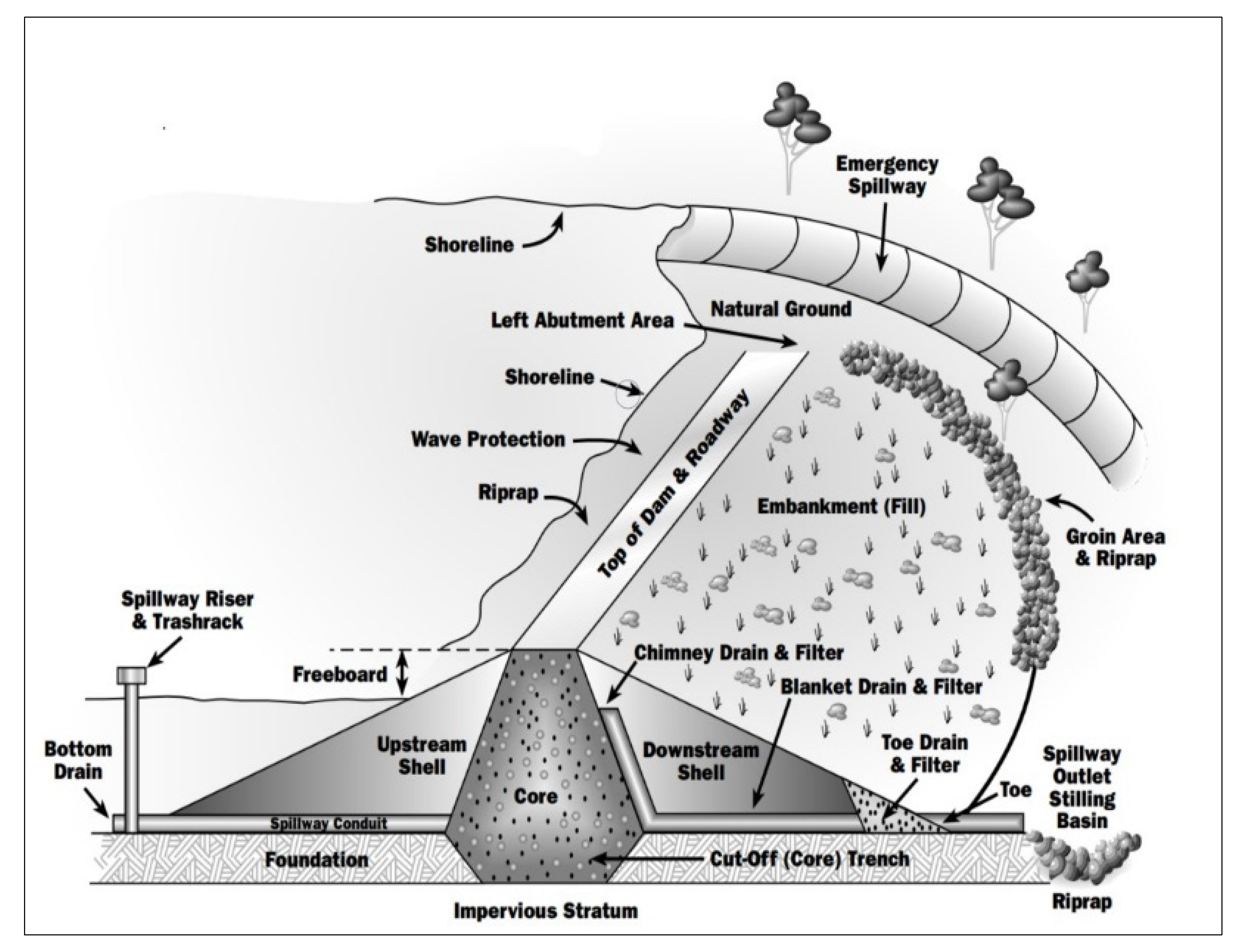
2.1. Embankment Dams
2.1.1. Earth-Fill Dams
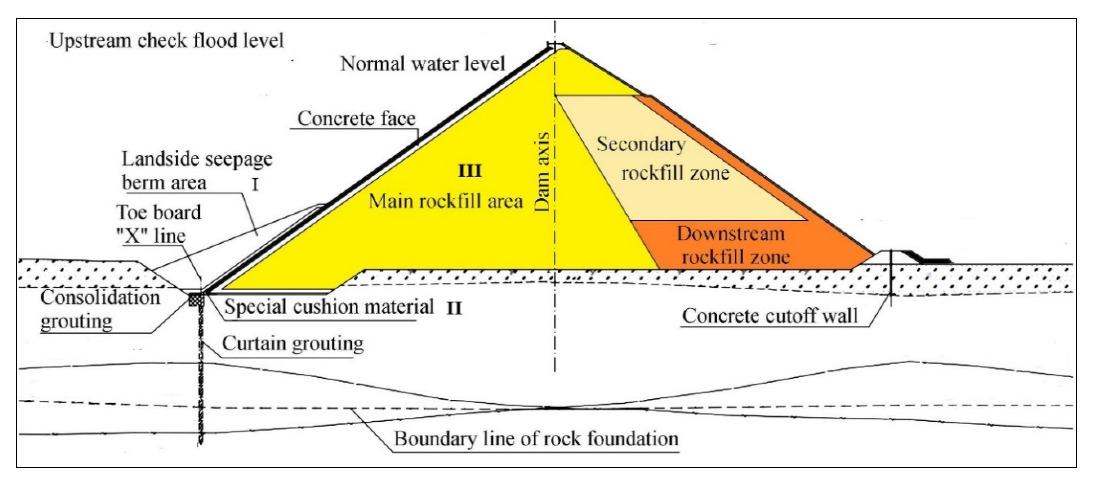
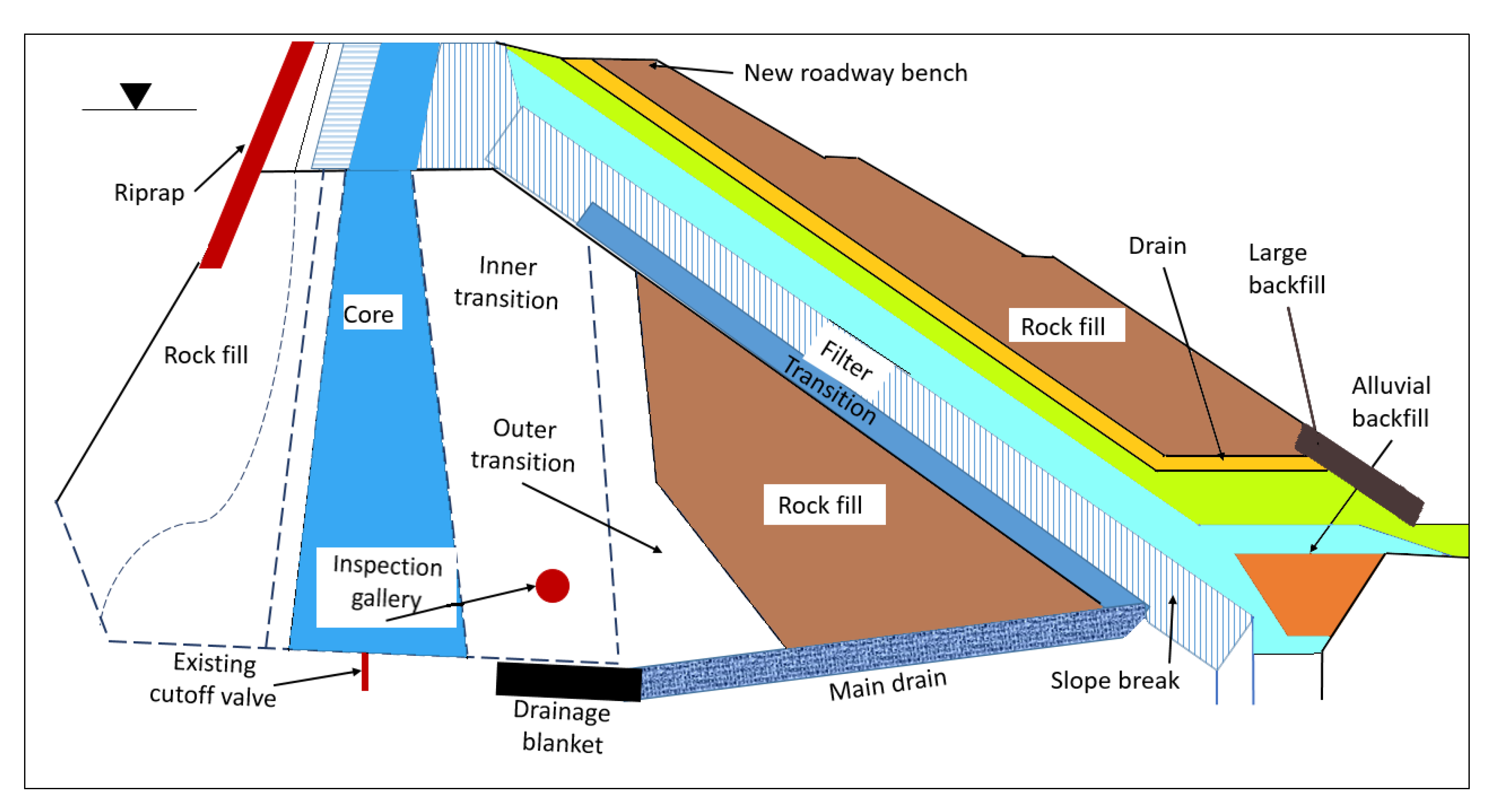
2.1.2. Rock-Fill Dam
2.2. Concrete Dams
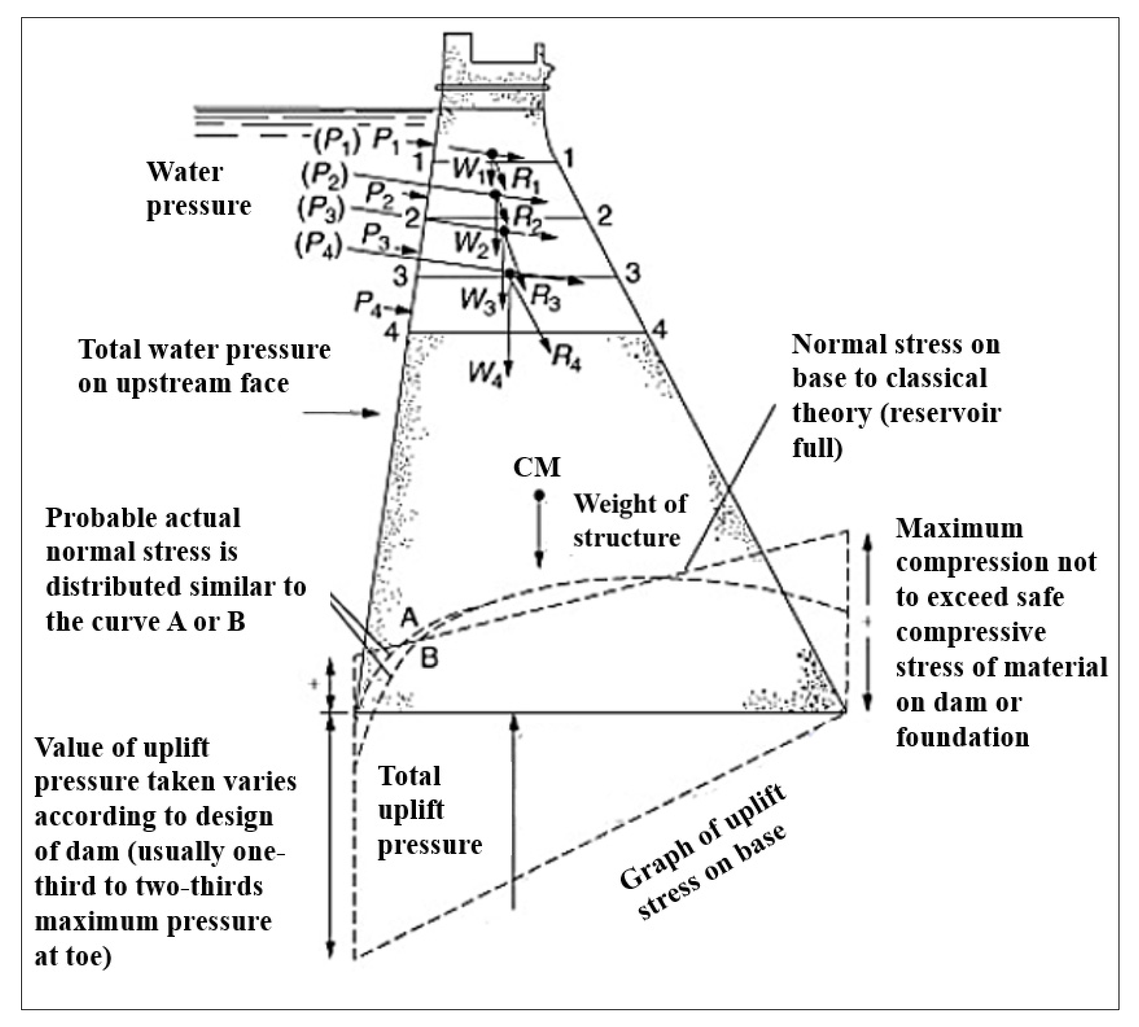
2.2.1. Gravity Dams
2.2.2. Buttress Dams
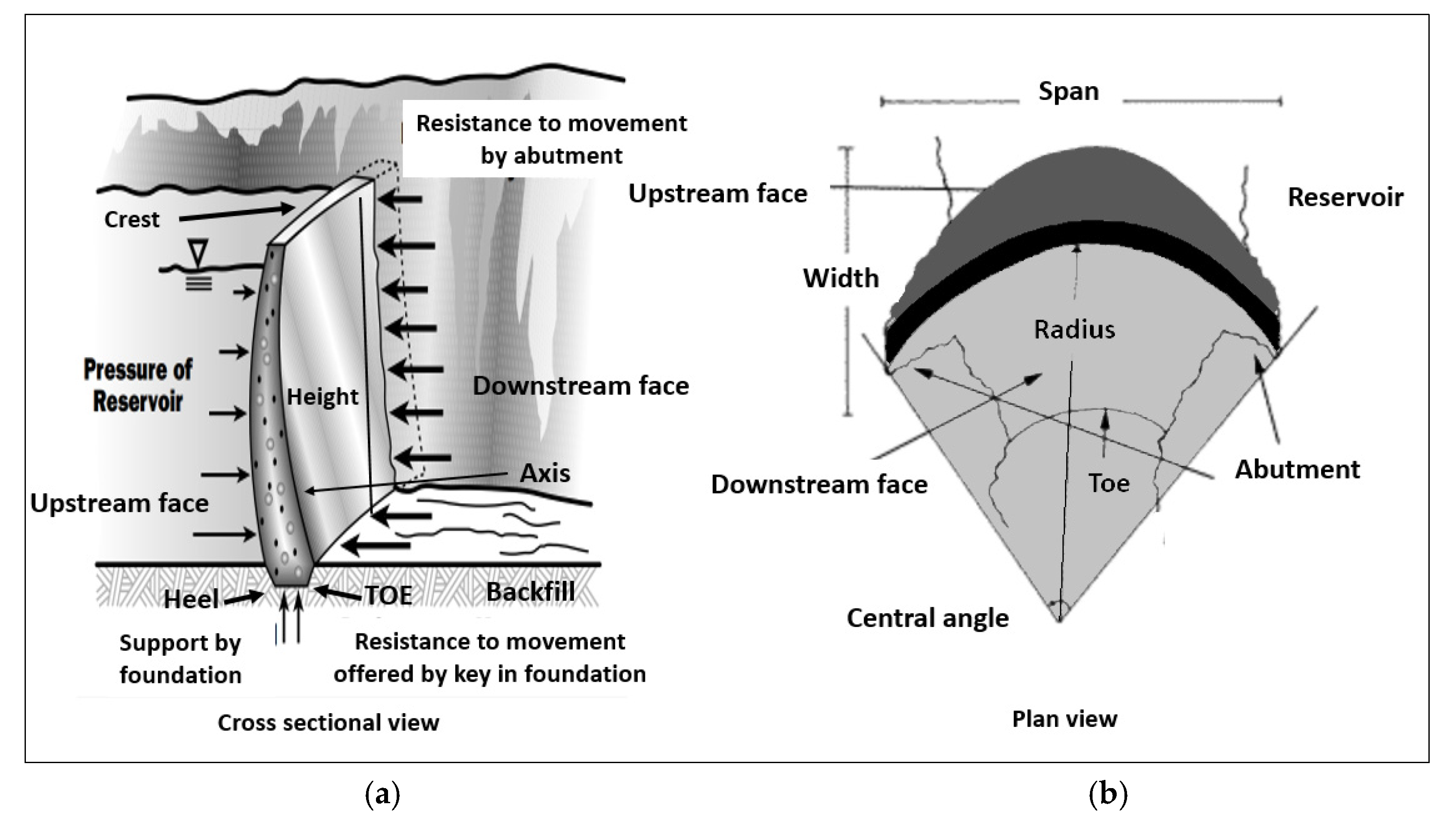
2.2.3. Arch Dams
2.3. Classification Based on Dam Size
2.4. Classification Based on Construction Material Rigidity
2.5. Classification Based on Vibration Effect
2.5.1. Embankment Dams (Large, Medium, Small)
2.5.2. Concrete Dams (Large, Medium, Small)
2.5.3. Composite Dam
3. Powerhouse
3.1. Powerhouse Facilities
3.1.1. Run-of-River
3.1.2. Storage
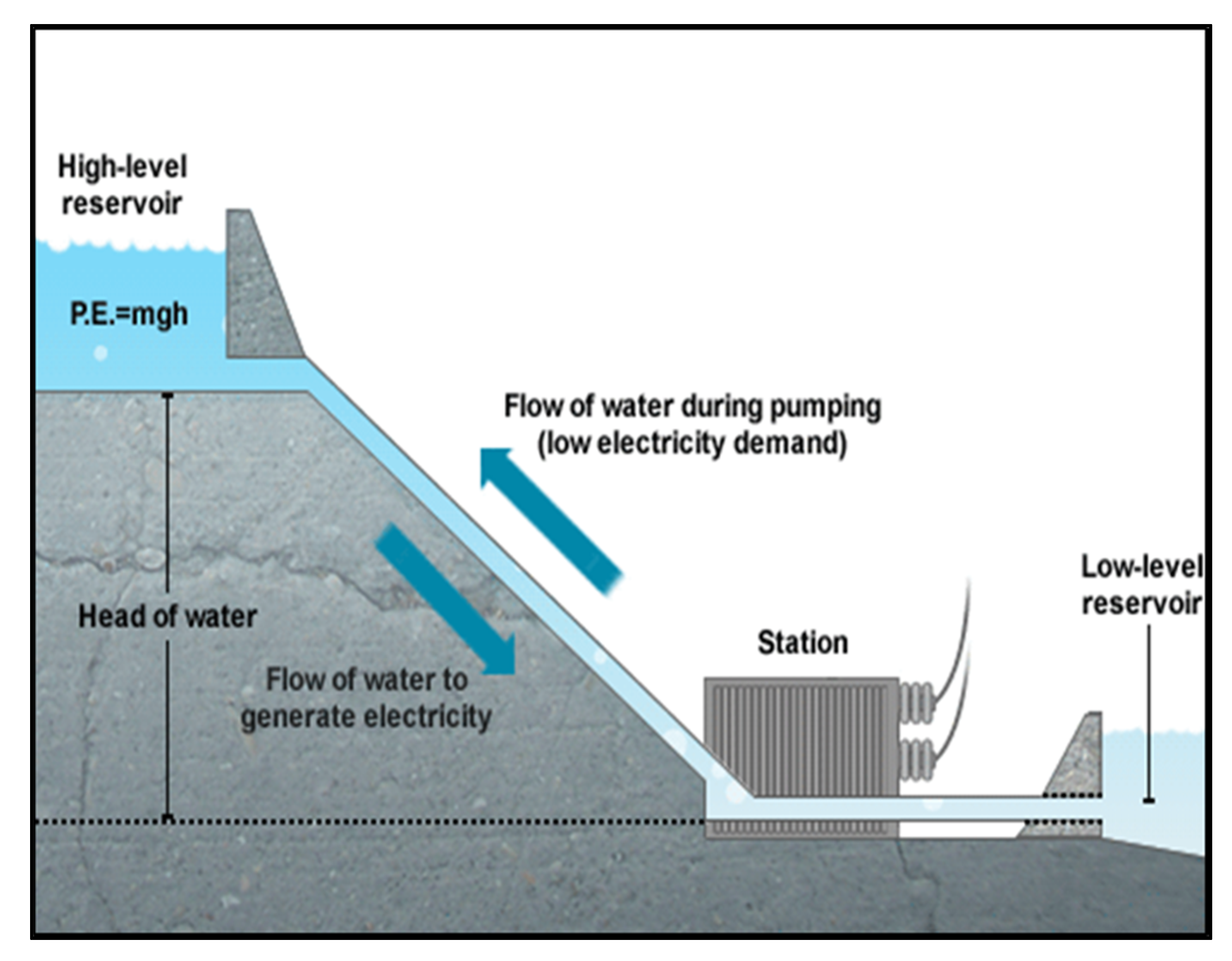
3.1.3. Pumped Storage
3.1.4. Micro Plant
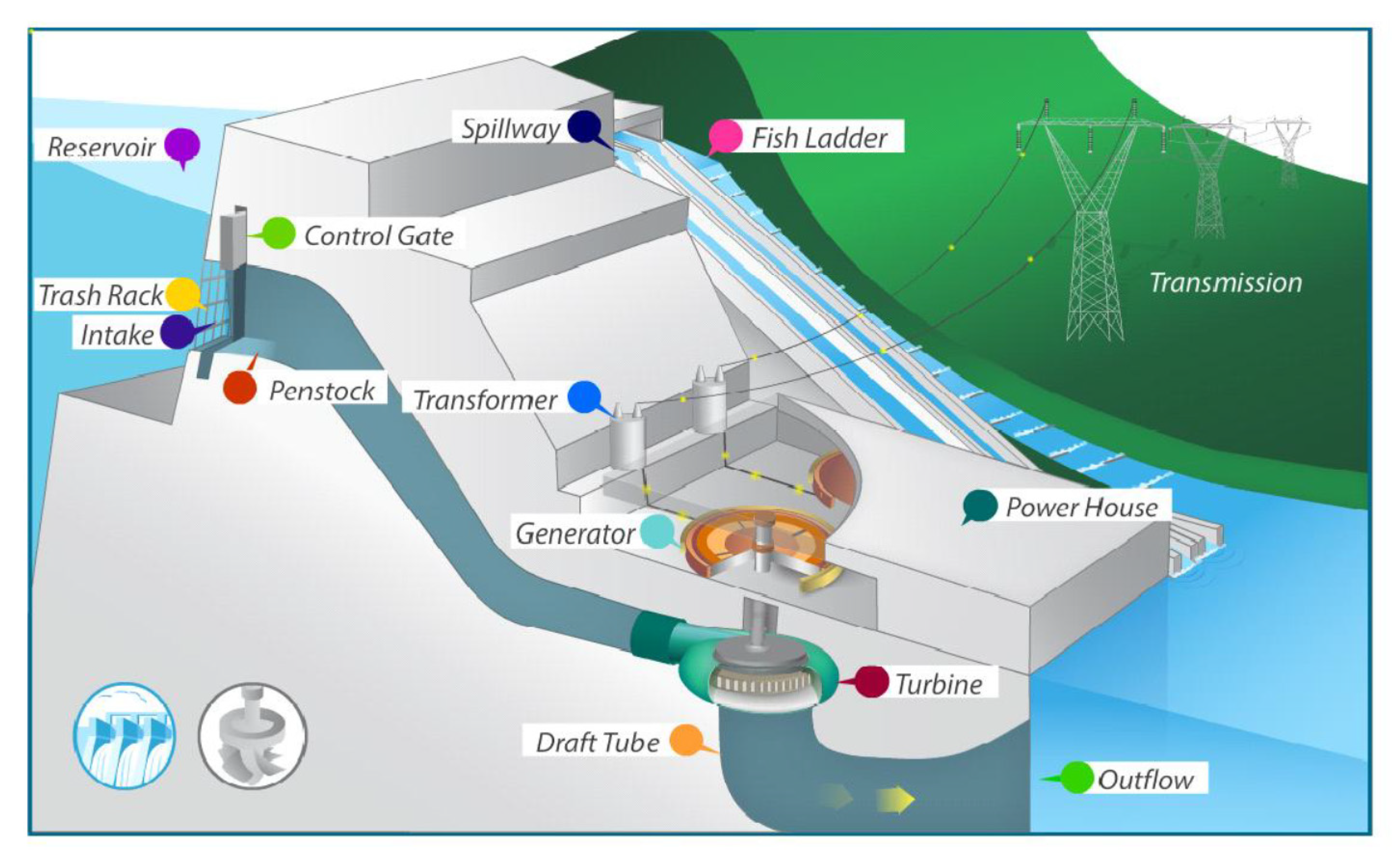
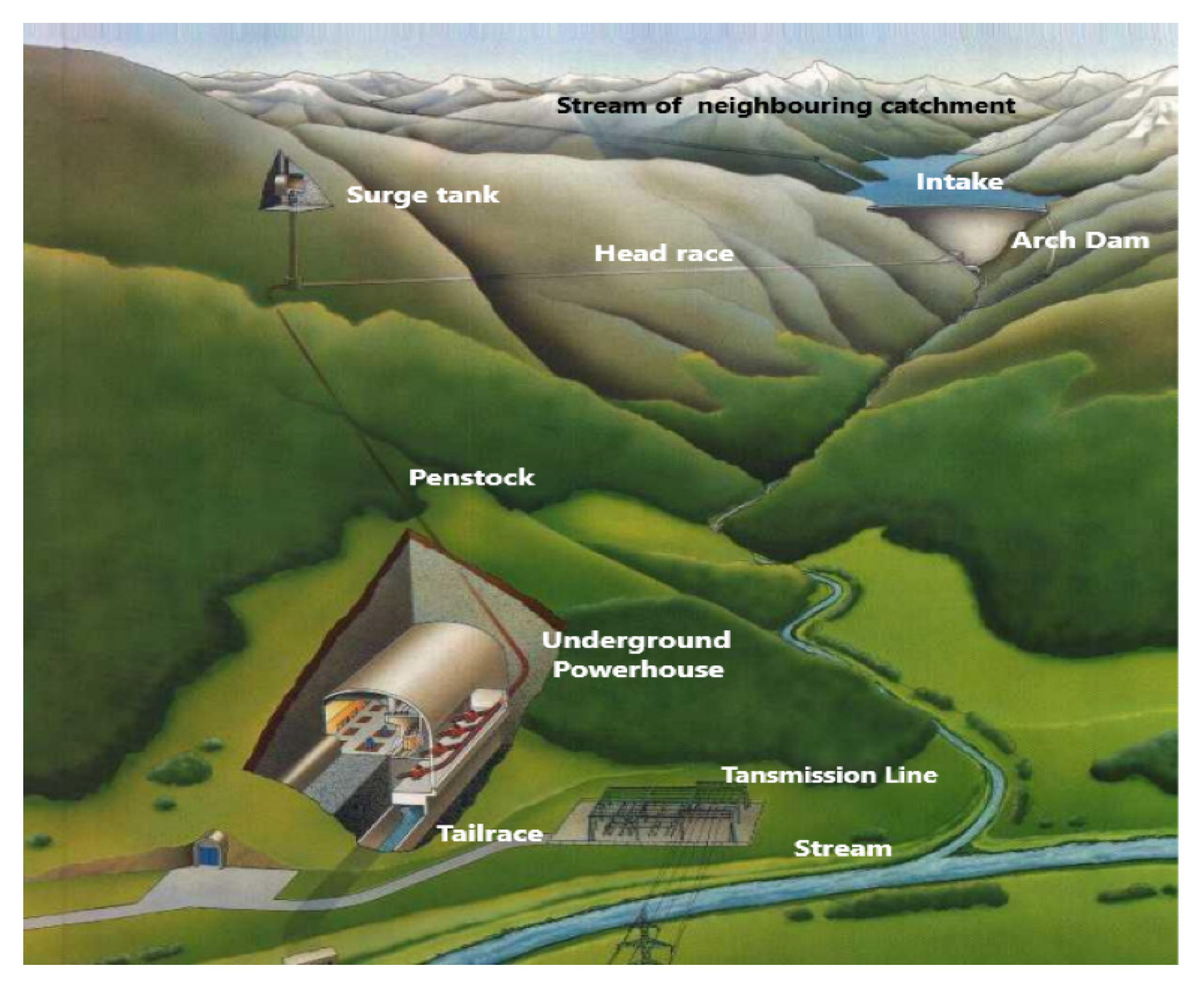
3.2. Main Components of a Plant
3.2.1. Intake, Penstock, and Surge Chamber
3.2.2. Turbines
- (1)
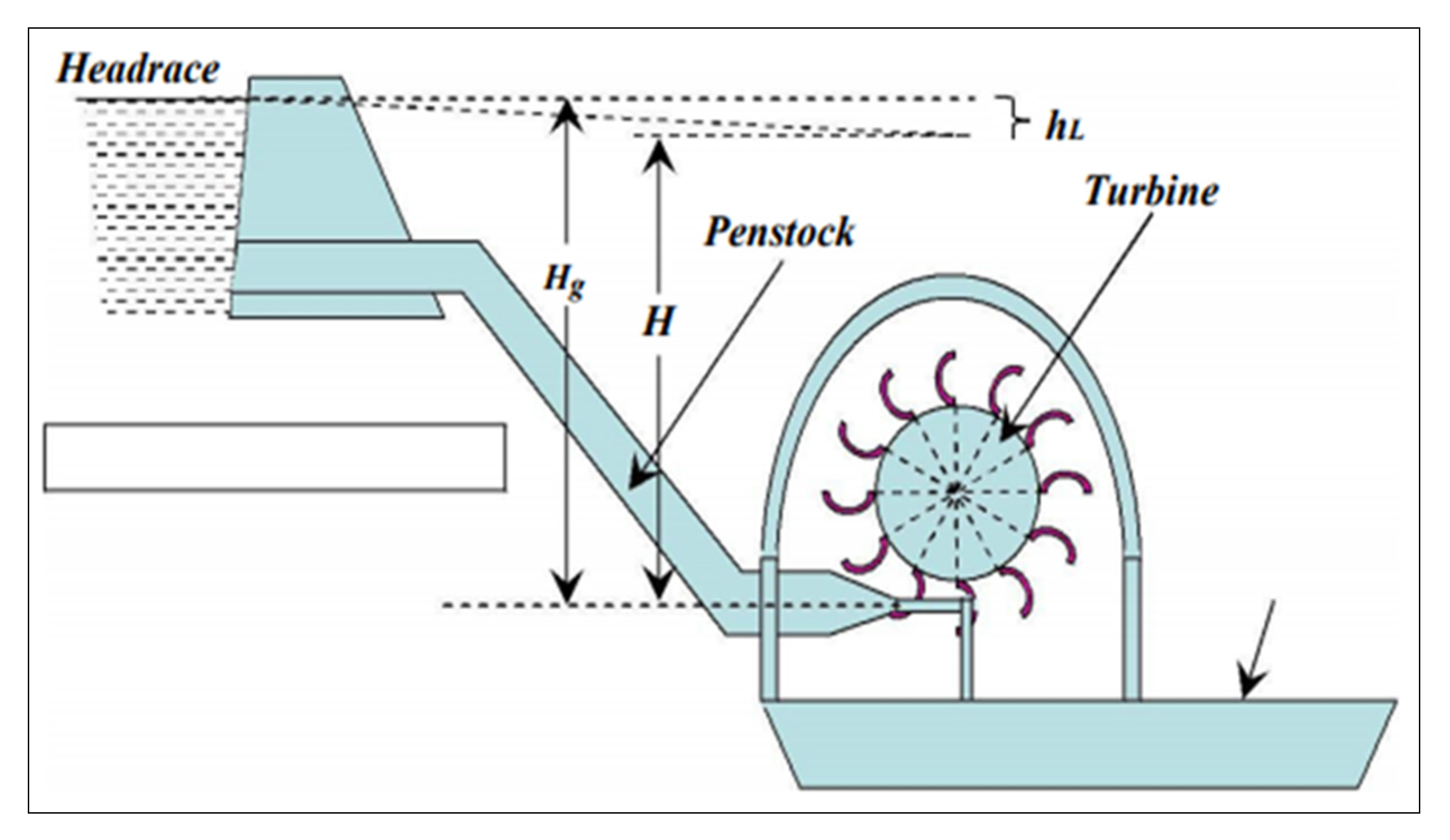
- Impulse turbines: As shown in Figure 9, these turbines allow water to enter into the casing with a substantial pressure and pass through where jets of water from a nozzle at a high speed strike the symmetrically shaped blades fixed to the rotor. The kinetic power of the water is transferred via momentum to the rotating wheel [80], and the strain is transferred to the inlet and the outlet. The resulting impulse from the jet helps to rotate the turbine, hence called impulse turbine [81,82,83,84].
- (2)
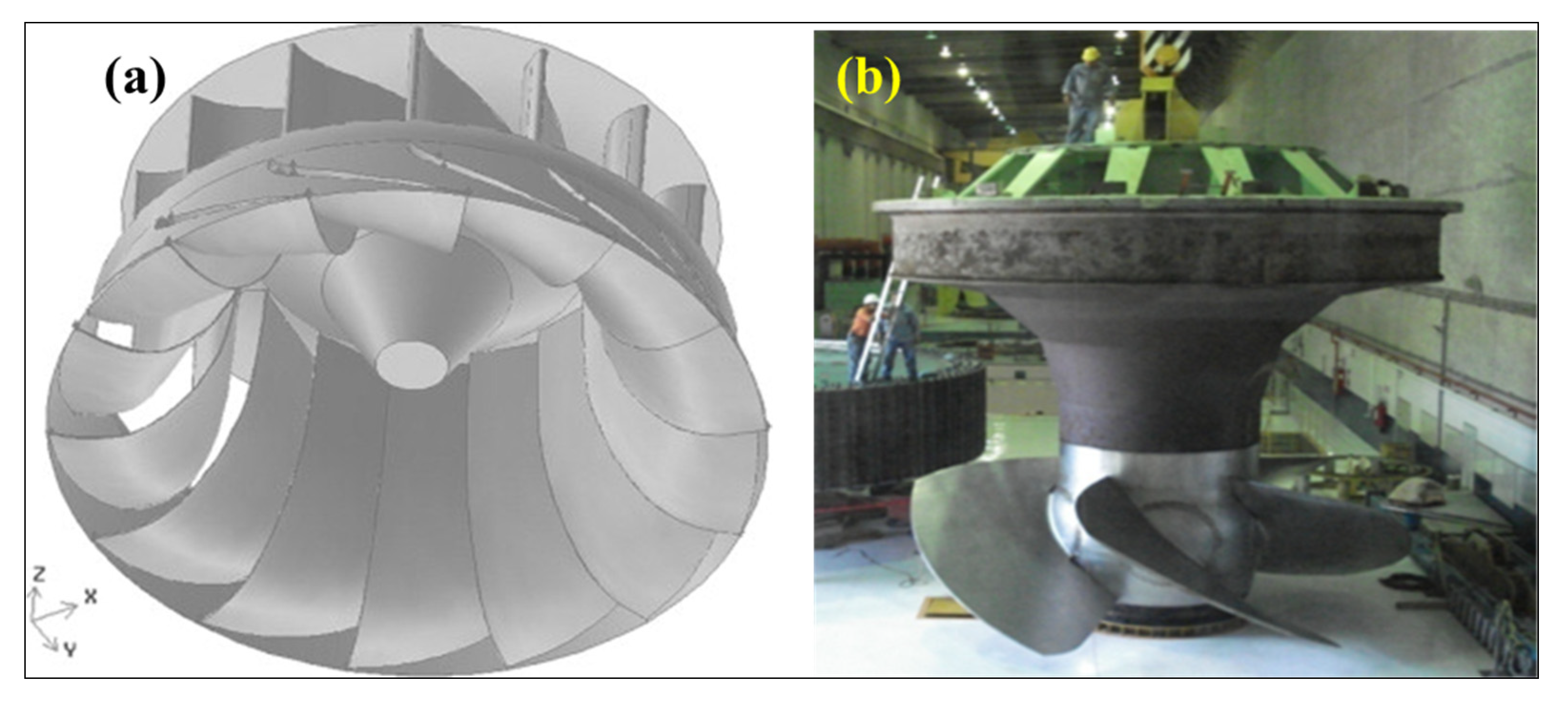
- Reaction turbines: This type of turbine takes water from upstream of the dam and transports it through the penstock under pressure where the vector sum of impulse and reactive force together strike the asymmetrical shape blades [85,86,87]. These turbines are constructed within the powerhouse that has been installed in different directions depending on the site topography, the head of water, and the discharge [88]. The types of reaction turbines are classified as Francis or Kaplan turbines as outlined in Figure 10.
3.2.3. Generators, Transformers, Transmission Lines, and Outlets
4. Finite Element Modeling
4.1. Computational Fluid Dynamics (CFD)
4.2. Vibration Effect on Dam Body
4.3. Earliest Dam Studies
- (1)
- Specific attributes of the water represent the reservoir mass added to the dam.
- (2)
- The Eulerian approach can be used to describe the dam–reservoir interaction [113]. The employed variables for this description are (i) displacements in the dam and (ii) pressure and velocity potential in the water.
- (3)
4.4. 2D Dam Modeling
4.5. 3D Dam Modeling
4.6. The Vibration of Turbines and Powerhouse
5. Turbine Analysis
5.1. Francis Turbine Modeling
5.2. Kaplan Turbine Modeling
6. Main Related Dam-Hydropower Plant Problems
6.1. Cavitation in the Draft Tube
6.2. Hydraulic Turbine Structure Design
6.3. Powerhouse Vibration Analysis
7. State-of-the-Art Assessment and Evaluation
- (1)
- Maximum and minimum water output choices,
- (2)
- Effect of vibration on the life of the operation,
- (3)
- Electricity-related deviations,
- (4)
- Environmental constraints,
- (5)
- Revenue variation and its effect on operational activities,
- (6)
- Market variation,
- (7)
- Policy changes, and
- (8)
- Hazards during operation affecting productivity.
8. Possible Future Research Directions
- (1)
- The operation of the powerhouse at the dam site is one of the important factors that should be considered in the analysis of dam safety. The effect of seismic activity on the dam body should be integrated with the powerhouse effect. Most of the published studies either only focused on reducing the impact of cavitation and pressure fluctuations in the turbine draft tube or on the analysis of seismic effect on the dam bodies. Hence, integration of the vibrational effect due to the operation of reaction turbines with and without seismic effects should be further investigated.
- (2)
- Over time, various advancing techniques have been used to model dam operation. Among several techniques, AI models have achieved great results and shown promises in the near future. AI models use various optimization techniques and models, which help designers to comprehensively assess, predict, and manage large amounts of data. This, in turn, helps policymakers, engineers, and project managers to manage and operate the system more efficiently. Many AI models have been applied to the modeling and operation of dams and reservoirs considering different stochastic hydrological parameters [241]. Many AI models have been employed; however, faster problem-solving models are required along with better optimizers, including methods that can select the input and manage non-linear data and more experimental data to develop an effective model.
- (3)
- Turbine productivity is usually determined based on the maximum and the minimum upstream water levels. Hence, for optimal turbine system operation, computations of the principal stresses within the dam body and powerhouse should be examined based on the water level.
- (4)
- In the majority of the published studies, turbine model evaluations within the dam powerhouse were investigated individually. Conceptually, this is not practical from an engineering point of view. The vibrational effect on the dam body and the powerhouse should be simulated as a cohesive unit.
- (5)
- Dam emergency action plans should be implemented, coupled with the development of improved systems for flood prediction.
- (6)
- The reliability of the dam gates must be improved to ensure the availability of all dams during a flood.
- (7)
- The main body of the dams should be grouted using cement to reduce leakages and improve performance.
- (8)
- The foundation drains must be renovated to ensure the drainage system is working properly; a good dissipation of uplift pressures must also be ensured.
- (9)
- Detailed seismic studies must be performed to analyze the chances of seismic-event-related failure modes.
- (10)
- A risk model architecture must be implemented.
- (11)
- Advancements in computer-based capabilities have resulted in the development of numerous methods for predicting the extent of cavitation development and its characteristics over propeller blades. Hence, CFD can be used to conduct turbine cavitation studies using a barotropic state equation.
- (12)
- The availability of data is crucial for dam construction, hydropower generation, ecological and hydrological protection, and smooth operational activities. However, regular, continuous, and reliable data are difficult to obtain. A well-equipped and strategically designed network of hydrological, water quality, and biological monitoring stations should be in place to collect data on aquatic animals, flow regime, water temperature, nutrients, and sediment load [242]. The environmental impact basement should be more detailed [243]. These assessments could help with more consistent and reliable policymaking, thereby increasing the applications of hydro-electrical dams.
- (13)
- By applying various assessments, monitoring, and simulation using previous dam data or prototype structure operational data, much better hydro-dams can be designed. In addition to that, for the more efficient performance of turbines and dams, there is need of economical maintenance methods, and mini-hydro plants are better suited for these purposes. They are cheaper, efficient and operation and maintenance is simpler than large projects. To increase the number of clean and sustainable energy sources, governments can support initiatives by providing financial subsidies like fixed feed-in or premium tariffs [244]. However, the number of subsidies provided and environmental impact per 1 MW production of energy must be estimated.
Author Contributions
Funding
Conflicts of Interest
References
- Zhang, L.; Peng, M.; Chang, D.; Xu, Y. Dam Failure Mechanisms and Risk Assessment; John Wiley & Sons: Hoboken, NJ, USA, 2015; ISBN 9781118558522. [Google Scholar]
- Bosshard, P. China Dams the World. World Policy J. 2009, 26, 43–51. [Google Scholar] [CrossRef]
- Nasir, B.A. Design considerations of micro-hydro-electric power plant. Energy Procedia 2014, 50, 19–29. [Google Scholar] [CrossRef]
- Weinberg, A.M. ‘Immortal’energy systems and intergenerational justice. Energy Policy 1985, 13, 51–59. [Google Scholar] [CrossRef]
- Mahmood, K.; Mundial, B. Reservoir Sedimentation: Impact, Extent, and Mitigation; World Bank: Washington, DC, USA, 1987. [Google Scholar]
- Kirchherr, J.; Charles, K.J. The social impacts of dams: A new framework for scholarly analysis. Environ. Impact Assess. Rev. 2016, 60, 99–114. [Google Scholar] [CrossRef]
- Lerer, L.B.; Scudder, T. Health impacts of large dams. Environ. Impact Assess. Rev. 1999, 19, 113–123. [Google Scholar] [CrossRef]
- Lejeune, A.; Hui, S.L. Hydro Power: A Multi Benefit Solution for Renewable Energy. In Comprehensive Renewable Energy; Elsevier: Amsterdam, The Netherlands, 2012; Volume 6, pp. 15–47. [Google Scholar]
- Padhy, M.K.; Saini, R.P. A review on silt erosion in hydro turbines. Renew. Sustain. Energy Rev. 2008, 12, 1974–1987. [Google Scholar] [CrossRef]
- Kjølle, A. Hydropower in Norway: Mechanical Equipment. In Proceedings of the IAHR Congress, Beijing, China, 16–21 September 2001. [Google Scholar]
- Neopane, H.P. Sediment Erosion in Hydro Turbines; Tapir Uttrykk: Trondheim, Norway, 2010. [Google Scholar]
- Yang, Y.; Chen, J.; Xiao, M. Analysis of seismic damage of underground powerhouse structure of hydropower plants based on dynamic contact force method. Shock Vib. 2014, 2014. [Google Scholar] [CrossRef]
- Dorji, U.; Ghomashchi, R. Hydro turbine failure mechanisms: An overview. Eng. Fail. Anal. 2014, 44, 136–147. [Google Scholar] [CrossRef]
- Mejia, L.H.; Seed, H.B. Comparison of 2-D and 3-D dynamic analyses of earth dams. J. Geotech. Eng. 1983. [Google Scholar] [CrossRef]
- Khosravi, S.; Heydari, M.M. Modelling of Concrete Gravity Dam Including Dam-Water-Foundation Rock Interaction. World Appl. Sci. J. 2013, 22, 538–546. [Google Scholar]
- Sarkar, R.; Paul, D.K.; Stempniewski, L. Influence of reservoir and foundation on the nonlinear dynamic response of concrete gravity dams. ISET J. Earthq. Technol. 2007, 44, 377–389. [Google Scholar]
- Zeidan, B.A. Effect of foundation flexibility on dam-reservoir-foundation interaction. In Proceedings of the Eighteenth International Water Technology Conference, Sharm El Sheikh, Egypt, 12–15 March 2015. [Google Scholar]
- Ebrahimian, B. Non-Linear Numerical Analysis of Earthquake-Induced Deformation of Earth-Fill Dams; INTECH Open Access Publisher: Rijeka, Croatia, 2012; ISBN 9535100254. [Google Scholar]
- Mircevska, V.J.; Bickovski, V.; Garevski, M. A 3D nonlinear dynamic analysis of a rock-fill dam based on IZIIS software. Acta Geotech. Slov. 2007, 4, 16–32. [Google Scholar]
- Bosioc, A.I.; Tanasa, C.; Muntean, S.; Susan-Resiga, R.F. Unsteady pressure measurements and numerical investigation of the jet control method in a conical diffuser with swirling flow. In Proceedings of the IOP Conference Series: Earth and Environmental Science; IOP Publishing: Bristol, UK, 2010; Volume 12, p. 12017. [Google Scholar]
- Casanova García, F.; Mantilla Viveros, C.A. Experimental analysis of the vibration on the draft tube of a Francis hydraulic turbine during operation at different power levels. Rev. Fac. Ing. Univ. Antioquia 2010, 55, 90–98. [Google Scholar]
- Lai, X.D.; Liao, G.L.; Zhu, Y.; Zhang, X.; Gou, Q.Q.; Zhang, W.B. Lateral vibration of hydro turbine-generator rotor with varying stiffness of guide bearings. In Proceedings of the IOP Conference Series: Earth and Environmental Science; IOP Publishing: Bristol, UK, 2012; Volume 15, p. 42006. [Google Scholar]
- Akkermann, J.; Runte, T.; Krebs, D. Ship lift at Three Gorges Dam, China–design of steel structures. Steel Constr. 2009, 2, 61–71. [Google Scholar] [CrossRef]
- Narita, K. Design and Construction of Embankment Dams. 2000. Available online: http://aitech.ac.jp/~narita/tembankmentdam1.pdf (accessed on 21 February 2020).
- Doyle, M.W.; Harbor, J.M.; Stanley, E.H. Toward policies and decision-making for dam removal. Environ. Manage. 2003, 31, 453–465. [Google Scholar] [CrossRef]
- Luo, Y.; Chen, L.; Xu, M.; Tong, X. Review of dam-break research of earth-rock dam combining with dam safety management. Procedia Eng. 2012, 28, 382–388. [Google Scholar]
- Altarejos-García, L.; Escuder-Bueno, I.; Serrano-Lombillo, A.; de Membrillera-Ortuño, M.G. Methodology for estimating the probability of failure by sliding in concrete gravity dams in the context of risk analysis. Struct. Saf. 2012, 36, 1–3. [Google Scholar] [CrossRef]
- Foster, M.; Fell, R.; Spannagle, M. The statistics of embankment dam failures and accidents. Can. Geotech. J. 2000, 37, 1000–1024. [Google Scholar] [CrossRef]
- Mishra, A.K. Engineering Geology, 1st ed.; S.CHAND &COMPANY PVT. LTD: New Delhi, India, 2014; ISBN 81-219-4322-1. [Google Scholar]
- Raleigh. Dam Operation, Maintenance and Inspection Manual; North Carolina Department of Environment and Natural Resources Division of Land Resources Land Quality Section: Raleigh, NC, USA, 1989.
- Chen, S.-H. Hydraulic Structures; Springer: Berlin/Heidelberg, Germany, 2015; ISBN 978-3-662-47330-6. [Google Scholar]
- Ali, A.A.; Al-Ansari, N.A.; Knutsson, S. Morphology of Tigris River within Baghdad City. Hydrol. Earth Syst. Sci. 2012, 16, 3783. [Google Scholar] [CrossRef]
- Hariri-Ardebili, M.A.; Seyed-Kolbadi, S.M. Seismic cracking and instability of concrete dams: Smeared crack approach. Eng. Fail. Anal. 2015, 52, 45–60. [Google Scholar] [CrossRef]
- Ratnayaka, D.D.; Brandt, M.J.; Johnson, M. Water Supply; Butterworth-Heinemann: Oxford, UK, 2009; ISBN 0080940846. [Google Scholar]
- Ghaemmaghami, A.R.; Ghaemian, M. Experimental seismic investigation of Sefid-rud concrete buttress dam model on shaking table. Earthq. Eng. Struct. Dyn. 2008, 37, 809–823. [Google Scholar] [CrossRef]
- Wieland, M. Features of seismic hazard in large dam projects and strong motion monitoring of large dams. Front. Archit. Civ. Eng. China 2010, 4, 56–64. [Google Scholar] [CrossRef]
- Akbari, J.; Ahmadi, M.T.; Moharrami, H. Advances in concrete arch dams shape optimization. Appl. Math. Model. 2011, 35, 3316–3333. [Google Scholar] [CrossRef]
- Wang, R.K.; Chen, L.; Zhang, C. Seismic design of Xiluodu ultra-high arch dam. Water Sci. Eng. 2018, 11, 288–301. [Google Scholar] [CrossRef]
- Zarfl, C.; Lumsdon, A.E.; Berlekamp, J.; Tydecks, L.; Tockner, K. A global boom in hydropower dam construction. Aquat. Sci. 2014, 77, 161–170. [Google Scholar] [CrossRef]
- Horlacher, H.; Heyer, T.; Ramos, C.M.; Da Silva, M.C. Management of Hydropower Impacts through Construction and Operation; Elsevier: Amsterdam, The Netherlands, 2012. [Google Scholar]
- POFF, N.L.; HART, D.D. How Dams Vary and Why It Matters for the Emerging Science of Dam Removal. Bioscience 2002, 52, 659. [Google Scholar] [CrossRef]
- IIED. Dams and Development: A New Framework for Decision-Making: Overview of the Report by the World Commission on Dam; Issue Paper 108, Drylands Programme; Earthscan: London, UK, 2001. [Google Scholar]
- Wehrmann, H.; Hübl, J.; Holzinger, G. Classification of Dams in Torrential Watersheds. In Proceedings of the INTERPRAEVENT International Symposium Disaster Mitigation of Debris Flows, Slope Failures and Landslides, Niigata, Japan, 25–29 September 2006; pp. 829–838. [Google Scholar]
- Goldin, A.L.; Rasskazov, L.N.; Zeidler, R.B. Design of earth dams; Routledge: London, UK, 2017; ISBN 9781351455848. [Google Scholar]
- Bretas, E.M.; Lemos, J.V.; Lourenço, P.B. Hydromechanical analysis of masonry gravity dams and their foundations. Rock Mech. rock Eng. 2013, 46, 327–339. [Google Scholar] [CrossRef]
- Qu, Y.; Zou, D.; Kong, X.; Liu, J.; Zhang, Y.; Yu, X. Seismic damage performance of the steel fiber reinforced face slab in the concrete-faced rockfill dam. Soil Dyn. Earthq. Eng. 2019, 119, 320–330. [Google Scholar] [CrossRef]
- Sherard, J.L.; Cooke, J.B. Concrete-face rockfill dam: I. Assessment. J. Geotech. Eng. 1987, 113, 1096–1112. [Google Scholar] [CrossRef]
- Rane, A.V.; Thakur, S.; Thakur, R. Rubber Dam—An Introduction. In Hydraulic Rubber Dam; Elsevier: Amsterdam, Netherlands, 2019; pp. 1–9. [Google Scholar]
- Previati, M.; Canone, D.; Bevilacqua, I.; Boetto, G.; Pognant, D.; Ferraris, S. Evaluation of wood degradation for timber check dams using time domain reflectometry water content measurements. Ecol. Eng. 2012, 44, 259–268. [Google Scholar] [CrossRef]
- Seed, H.B. Considerations in the earthquake-resistant design of earth and rockfill dams. Geotechnique 1979, 29, 215–263. [Google Scholar] [CrossRef]
- Severn, R.T.; Jeary, A.P.; Ellis, B.R. BRE FORCED VIBRATION TESTS AND THEORETICAL STUDIES ON DAMS. Proc. Inst. Civ. Eng. 1980, 69, 605–634. [Google Scholar]
- Brownjohn, J.M.W.; Severn, R.T.; Taylor, C.A. Ambient Vibration Survey of Contra Dam; University of Bristol, Department of Civil Engineering: Bristol, UK, 1986. [Google Scholar]
- Andrianopoulos, K.I.; Papadimitriou, A.G.; Bouckovalas, G.D.; Karamitros, D.K. Insight into the seismic response of earth dams with an emphasis on seismic coefficient estimation. Comput. Geotech. 2014, 55, 195–210. [Google Scholar] [CrossRef]
- Dakoulas, P.; Gazetas, G. Seismic shear vibration of embankment dams in semi-cylindrical valleys. Earthq. Eng. Struct. Dyn. 1986, 14, 19–40. [Google Scholar] [CrossRef]
- Gazetas, G.; Dakoulas, P. Seismic analysis and design of rockfill dams: state-of-the-art. Soil Dyn. Earthq. Eng. 1992, 11, 27–61. [Google Scholar] [CrossRef]
- Kontoe, S.; Han, B.; Pelecanos, L.; Zdravkovic, L. Seismic response of earthfill and rockfill embankment dams. In Proceedings of the 3rd Meeting of EWG Dams and Earthquakes—an International Symposium, Lisbon, Portugal, 6–8 May 2019. [Google Scholar]
- Chakraborty, S.; Das, J.T.; Puppala, A.J.; Banerjee, A. Natural frequency of earthen dams at different induced strain levels. Eng. Geol. 2019, 248, 330–345. [Google Scholar] [CrossRef]
- Esmaielzadeh, S.; Ahmadi, H.; Hosseini, S.A. Damage detection in concrete gravity dams using signal processing algorithms based on earthquake vibrations. J. Vibroeng. 2019, 21, 2196–2215. [Google Scholar]
- Esmaielzadeh, S.; Ahmadi, H.; Hosseini, S.A. Damage Detection of Concrete Gravity Dams using Hilbert-Huang Method. J. Appl. Eng. Sci. 2019, 8, 7–16. [Google Scholar] [CrossRef]
- Bukenya, P.; Moyo, P.; Beushausen, H.; Oosthuizen, C. Health monitoring of concrete dams: A literature review. J. Civ. Struct. Heal. Monit. 2014, 4, 235–244. [Google Scholar] [CrossRef]
- Chang, N.-Y.; Oncul, F. A Parametric Study on Seismic Behavior of a Composite Dam. In Proceedings of the Soil Dynamics and Liquefaction 2000; American Society of Civil Engineers: Reston, VA, USA, 2000; pp. 178–190. [Google Scholar]
- Kim, D.-S.; Kim, M.-K.; Kim, S.-H.; Choo, Y.-W. Seismic behaviors of earth-core, concrete-faced-rock-fill, and composite dams. Citeseer 2012. [Google Scholar]
- Cui, J.; Shen, Z. Characteristics of Earthquake Induced Permanent Deformation of a High Composite Dam with Asphalt Concrete Core Wall. Water Resour. Power 2010, 28, 73–77. [Google Scholar]
- Sevim, B.; Bayraktar, A.; Altunişik, A.C. Finite element model calibration of berke arch dam using operational modal testing. J. Vib. Control 2011, 17, 1065–1079. [Google Scholar] [CrossRef]
- Schleiss, A.J.; Boes, R.M. Dams and Reservoirs under Changing Challenges; CRC press: Boca Raton, FL, USA, 2011; ISBN 0203804090. [Google Scholar]
- Zhang, S.; Wang, G.; Yu, X. Seismic cracking analysis of concrete gravity dams with initial cracks using the extended finite element method. Eng. Struct. 2013, 56, 528–543. [Google Scholar] [CrossRef]
- Amini, F.; Sama, K.M. Behavior of stratified sand–silt–gravel composites under seismic liquefaction conditions. Soil Dyn. Earthq. Eng. 1999, 18, 445–455. [Google Scholar] [CrossRef]
- Sharma, A.K.; Thakur, N.S. Energy situation, current status and resource potential of run of the river (RoR) large hydro power projects in Jammu and Kashmir: India. Renew. Sustain. Energy Rev. 2017, 78, 233–251. [Google Scholar] [CrossRef]
- Li, J.; Ameen, A.; Mohammad, T.; Al-Ansari, N.; Yaseen, Z. A Systematic Operation Program of a Hydropower Plant Based on Minimizing the Principal Stress: Haditha Dam Case Study. Water 2018, 10, 1270. [Google Scholar] [CrossRef]
- Ameen, A.; Ibrahim, Z.; Othman, F.; Al-Ansari, N.; Yaseen, Z. Minimizing the principle stresses of powerhoused Rock-Fill dams using control turbine running units: Application of Finite Element Method. Water 2018, 10, 1138. [Google Scholar] [CrossRef]
- Avakyan, T. Distribution Systems with Renewable Sources. Master’s Thesis, Czech Technical University, Prague, Czech Republic, 2017. [Google Scholar]
- Gielen, D. Renewable energy technologies: cost analysis series. Sol Photovolt 2012, 1, 52. [Google Scholar]
- Quaranta, E.; Revelli, R. Gravity water wheels as a micro hydropower energy source: A review based on historic data, design methods, efficiencies and modern optimizations. Renew. Sustain. Energy Rev. 2018, 97, 414–427. [Google Scholar] [CrossRef]
- Emiliano Corà, (EUREC). Hydropower Technologies: The State-of-the-Art. 2019. Available online: https://consultation.hydropower-europe.eu/assets/consultations/2019.08.13%20HydropowerTechnology_State%20of%20the%20Art%20FINAL.pdf (accessed on 21 February 2020).
- Wahlstrom, E.E. Dams, Dam Foundations, and Reservoir Sites. Developments in Geotechnical Engineering volume 6; Elsevier Scientific Publishing Company: Amsterdam, The Netherlands; Oxford, UK; New York, NY, USA, 1975; Volume 6. [Google Scholar]
- Suul, J.A.; Uhlen, K.; Undeland, T. Variable speed pumped storage hydropower for integration of wind energy in isolated grids: case description and control strategies. In Proceedings of the Nordic Workshop on Power and Industrial Electronics (NORPIE/2008), Espoo, Finland, 9–11 June 2008; Helsinki University of Technology: Espoo, Finland, 2008. [Google Scholar]
- Razan, J.I.; Islam, R.S.; Hasan, R.; Hasan, S.; Islam, F. A comprehensive study of micro-hydropower plant and its potential in Bangladesh. ISRN Renew. Energy 2012, 2012. [Google Scholar] [CrossRef]
- Sharma, H.; Singh, J. Run off river plant: status and prospects. Int. J. Innov. Technol. Explor. Eng. 2013, 3, 210–213. [Google Scholar]
- Sangal, S.; Garg, A.; Kumar, D. Review of optimal selection of turbines for hydroelectric projects. Int. J. Emerg. Technol. Adv. Eng. 2013, 3, 424–430. [Google Scholar]
- Cobb, B.R.; Sharp, K. V Impulse (Turgo and Pelton) turbine performance characteristics and their impact on pico-hydro installations. Renew. Energy 2013, 50, 959–964. [Google Scholar] [CrossRef]
- Linhardt, H.D.; Silvern, D.H. Analysis of partial admission axial impulse turbines. ARS J. 1961, 31, 297–308. [Google Scholar] [CrossRef]
- Židonis, A.; Benzon, D.S.; Aggidis, G.A. Development of hydro impulse turbines and new opportunities. Renew. Sustain. Energy Rev. 2015, 51, 1624–1635. [Google Scholar] [CrossRef][Green Version]
- Jayashankar, V.; Anand, S.; Geetha, T.; Santhakumar, S.; Kumar, V.J.; Ravindran, M.; Setoguchi, T.; Takao, M.; Toyota, K.; Nagata, S. A twin unidirectional impulse turbine topology for OWC based wave energy plants. Renew. Energy 2009, 34, 692–698. [Google Scholar] [CrossRef]
- Setoguchi, T.; Santhakumar, S.; Maeda, H.; Takao, M.; Kaneko, K. A review of impulse turbines for wave energy conversion. Renew. Energy 2001, 23, 261–292. [Google Scholar] [CrossRef]
- Quaranta, E. Optimal Rotational Speed of Kaplan and Francis Turbines with Focus on Low-Head Hydropower Applications and Dataset Collection. J. Hydraul. Eng. 2019, 145, 4019043. [Google Scholar] [CrossRef]
- Židonis, A.; Aggidis, G.A. State of the art in numerical modelling of Pelton turbines. Renew. Sustain. Energy Rev. 2015, 45, 135–144. [Google Scholar] [CrossRef]
- Trivedi, C.; Gandhi, B.; Michel, C.J. Effect of transients on Francis turbine runner life: a review. J. Hydraul. Res. 2013, 51, 121–132. [Google Scholar] [CrossRef]
- Paish, O. Small hydro power: Technology and current status. Renew. Sustain. Energy Rev. 2002, 6, 537–556. [Google Scholar] [CrossRef]
- Negru, R.; Muntean, S.; Marsavina, L.; Susan-Resiga, R.; Pasca, N. Computation of stress distribution in a Francis turbine runner induced by fluid flow. Comput. Mater. Sci. 2012, 64, 253–259. [Google Scholar] [CrossRef]
- Urquiza, G.; Garcia, J.C.; Gonzalez, J.G.; Castro, L.; Rodriguez, J.A.; Basurto-Pensado, M.A.; Mendoza, O.F. Failure analysis of a hydraulic Kaplan turbine shaft. Eng. Fail. Anal. 2014, 41, 108–117. [Google Scholar] [CrossRef]
- Moradi, S.; Yeganeh, A.; Salimi, M. CFD-modeling of effects of draft tubes on operating condition in spouted beds. Appl. Math. Model. 2013, 37, 1851–1859. [Google Scholar] [CrossRef]
- Ribeiro, A.F.; Guedes, M.C.M.; Smirnov, G.V.; Vilela, S. On the optimal control of a cascade of hydro-electric power stations. Electr. Power Syst. Res. 2012, 88, 121–129. [Google Scholar] [CrossRef]
- Kougias, I.; Aggidis, G.; Avellan, F.; Deniz, S.; Lundin, U.; Moro, A.; Muntean, S.; Novara, D.; Pérez-Díaz, J.I.; Quaranta, E. Analysis of emerging technologies in the hydropower sector. Renew. Sustain. Energy Rev. 2019, 113, 109257. [Google Scholar] [CrossRef]
- Muhirwa, A.; Cai, W.-H.; Su, W.-T.; Liu, Q.; Binama, M.; Li, B.; Wu, J. A Review on Remedial Attempts to Counteract the Power Generation Compromise from Draft Tubes of Hydropower plants. Renew. Energy 2019. [Google Scholar] [CrossRef]
- De Araújo, J.; Awruch, A.M. Probabilistic finite element analysis of concrete gravity dams. Adv. Eng. Softw. 1998, 29, 97–104. [Google Scholar] [CrossRef]
- Versteeg, H.K.; Malalasekera, W.; Orsi, G.; Ferziger, J.H.; Date, A.W.; Anderson, J.D. An Introduction to Computational Fluid Dynamics—The Finite Volume Method; Pearson Education Limited: London, UK, 1995; ISBN 9783540594345. [Google Scholar]
- Bhajantri, M.R.; Eldho, T.I.; Deolalikar, P.B. Hydrodynamic modelling of flow over a spillway using a two-dimensional finite volume-based numerical model. Sadhana 2006, 31, 743–754. [Google Scholar] [CrossRef]
- Cervera, M.; Oliver, J.; Faria, R. Seismic evaluation of concrete dams via continuum damage models. Earthq. Eng. Struct. Dyn. 1995, 24, 1225–1245. [Google Scholar] [CrossRef]
- Callari, C.; Abati, A. Finite element methods for unsaturated porous solids and their application to dam engineering problems. Comput. Struct. 2009, 87, 485–501. [Google Scholar] [CrossRef]
- Eastwood, J.W. An introduction to computational fluid mechanics. Comput. Phys. Commun. 1980, 20, 321–322. [Google Scholar] [CrossRef]
- Valiani, A.; Caleffi, V.; Zanni, A. Case study: Malpasset dam-break simulation using a two-dimensional finite volume method. J. Hydraul. Eng. 2002, 128, 460–472. [Google Scholar] [CrossRef]
- Vosoughifar, H.R.; Dolatshah, A.; Sadat Shokouhi, S.K. Discretization of multidimensional mathematical equations of dam break phenomena using a novel approach of finite volume method. J. Appl. Math. 2013, 2013. [Google Scholar] [CrossRef]
- Ferziger, J.H.; Peric, M. Computational Methods for Fluid Dynamics; Springer Science & Business Media: Berlin/Heidelberg, Germany, 2012; ISBN 3642560261. [Google Scholar]
- Khan, L.A.; Wicklein, E.A.; Rashid, M.; Ebner, L.L.; Richards, N.A. Computational fluid dynamics modeling of turbine intake hydraulics at a hydropower plant. J. Hydraul. Res. 2004, 42, 61–69. [Google Scholar] [CrossRef]
- Teklemariam, E.; Korbaylo, B.W.; Groeneveld, J.L.; Fuchs, D.M. Computational fluid dynamics: Diverse applications in hydropower project’s design and analysis. In Proceedings of the CWRA 55th Annual Conference, Winnipeg, MB, Canada, 11–14 June 2002. [Google Scholar]
- Pascau, A.; Pérez, C.; Serón, F.J. A comparison of segregated and coupled methods for the solution of the incompressible Navier-Stokes equations. Commun. Numer. Methods Eng. 1996, 12, 617–630. [Google Scholar] [CrossRef]
- Benzon, D.S.; Aggidis, G.A.; Anagnostopoulos, J.S. Development of the Turgo Impulse turbine: Past and present. Appl. Energy 2016, 166, 1–18. [Google Scholar] [CrossRef]
- Quaranta, E.; Katopodis, C.; Revelli, R.; Comoglio, C. Turbulent flow field comparison and related suitability for fish passage of a standard and a simplified low-gradient vertical slot fishway. River Res. Appl. 2017, 33, 1295–1305. [Google Scholar] [CrossRef]
- Yilmazturk, S.M.; Arici, Y.; Binici, B. Seismic assessment of a monolithic RCC gravity dam including three dimensional dam–foundation–reservoir interaction. Eng. Struct. 2015, 100, 137–148. [Google Scholar] [CrossRef]
- Xiong, M.; Huang, Y. Stochastic seismic response and dynamic reliability analysis of slopes: A review. Soil Dyn. Earthq. Eng. 2017, 100, 458–464. [Google Scholar] [CrossRef]
- Fenves, G.; Chopra, A.K. Simplified earthquake analysis of concrete gravity dams: Separate hydrodynamic and foundation interaction effects. J. Eng. Mech. 1985, 111, 715–735. [Google Scholar] [CrossRef]
- Bouaanani, N.; Paultre, P.; Proulx, J. A closed-form formulation for earthquake-induced hydrodynamic pressure on gravity dams. J. Sound Vib. 2003, 261, 573–582. [Google Scholar] [CrossRef]
- Bouaanani, N.; Paultre, P. A new boundary condition for energy radiation in covered reservoirs using BEM. Eng. Anal. Bound. Elem. 2005, 29, 903–911. [Google Scholar] [CrossRef]
- Birk, C.; Ruge, P. Representation of radiation damping in a dam–reservoir interaction analysis based on a rational stiffness approximation. Comput. Struct. 2007, 85, 1152–1163. [Google Scholar] [CrossRef]
- Bouaanani, N.; Lu, F.Y. Assessment of potential-based fluid finite elements for seismic analysis of dam–reservoir systems. Comput. Struct. 2009, 87, 206–224. [Google Scholar] [CrossRef]
- Fathi, A.; Lotfi, V. EFFECTS OF RESERVOIR LENGTH ON DYNAMIC ANALYSIS OF CONCRETE GRAVITY DAMS. In Proceedings of the 14th World Conference on Earthquake Engineering, Beijing, China, 12–17 October 2008. [Google Scholar]
- Lotfi, V. Seismic analysis of concrete gravity dams by decoupled modal approach in time domain. Electron. J. Struct. Eng. 2003, 3, 102–116. [Google Scholar]
- Shariatmadar, H. Modal Response of Dam-Reservoir-Foundation Interaction. J. Math. 2009. [Google Scholar]
- Gui, M.-W.; Chiu, H.-T. Seismic response of Renyitan earth-fill dam. J. Geoengin. 2009, 4, 41–50. [Google Scholar]
- Khazaee, A.; Lotfi, V. Application of perfectly matched layers in the transient analysis of dam–reservoir systems. Soil Dyn. Earthq. Eng. 2014, 60, 51–68. [Google Scholar] [CrossRef]
- Lotfi, V. MAP-76: A Program for Analysis of Concrete Dams; Amirkabir University of Technology: Tehran, Iran, 2001. [Google Scholar]
- Wang, X.; Jin, F.; Prempramote, S.; Song, C. Time-Domain Analysis of Gravity Dam–Reservoir Interaction Using High-Order Doubly Asymptotic Open Boundary. Seism. Saf. Eval. Concr. Dams 2013, 89, 139–171. [Google Scholar]
- Miquel, B.; Bouaanani, N. Accounting for earthquake-induced dam-reservoir interaction using modified accelerograms. J. Struct. Eng. 2013, 139, 1608–1617. [Google Scholar] [CrossRef]
- Mehdipour, B. Effect of Foundation on Seismic Behavior of Concrete Dam Considering the Interaction of Dam-Reservoir. J. Basic Appl. Sci. Res. 2013, 3, 13–20. [Google Scholar]
- Anastasiadis, A.; Klimis, N.; Makra, K.; Margaris, B. On seismic behaviour of a 130 m high rockfill dam: An integrated approach. In Proceedings of the 13th Conference on Earthquake Engineering, Vancouver, BC, Canada, 1–6 August 2004; p. 2933. [Google Scholar]
- Ohmachi, T.; Tahara, T. Analyses on earthquake-induced settlement of the Aratozawa dam due to the 2008 Iwate-Miyagi Nairiku earthquake, Japan. In Proceedings of the Validation of Dynamic Analyses of Dams and Their Equipment: Edited Contributions to the International Symposium on the Qualification of Dynamic Analyses of Dams and their Equipments, Saint-Malo, France, 31 August–2 September 2016; CRC Press: Boca Raton, FL, USA, 2018; p. 277. [Google Scholar]
- Mouyeaux, A.; Carvajal, C.; Bressolette, P.; Peyras, L.; Breul, P.; Bacconnet, C. Probabilistic stability analysis of an earth dam by Stochastic Finite Element Method based on field data. Comput. Geotech. 2018, 101, 34–47. [Google Scholar] [CrossRef]
- Løkke, A.; Chopra, A.K. Direct finite element method for nonlinear earthquake analysis of concrete dams: Simplification, modeling, and practical application. Earthq. Eng. Struct. Dyn. 2019, 48, 818–842. [Google Scholar] [CrossRef]
- Mohammadnezhad, H.; Ghaemian, M.; Noorzad, A. Seismic analysis of dam-foundation-reservoir system including the effects of foundation mass and radiation damping. Earthq. Eng. Eng. Vib. 2019, 18, 203–218. [Google Scholar] [CrossRef]
- Ghaemian, M.; Noorzad, A.; Mohammadnezhad, H. Assessment of foundation mass and earthquake input mechanism effect on dam–reservoir–foundation system response. Int. J. Civ. Eng. 2019, 17, 473–480. [Google Scholar] [CrossRef]
- Mouyeaux, A.; Carvajal, C.; Bressolette, P.; Peyras, L.; Breul, P.; Bacconnet, C. Probabilistic analysis of pore water pressures of an earth dam using a random finite element approach based on field data. Eng. Geol. 2019, 259, 105190. [Google Scholar] [CrossRef]
- Sotoudeh, M.A.; Ghaemian, M.; Sarvghad Moghadam, A. Determination of limit-states for near-fault seismic fragility assessment of concrete gravity dams. Sci. Iran. 2019, 26, 1135–1155. [Google Scholar] [CrossRef]
- Dakoulas, P. Longitudinal vibrations of tall concrete faced rockfill dams in narrow canyons. Soil Dyn. Earthq. Eng. 2012, 41, 44–58. [Google Scholar] [CrossRef]
- Hariri-Ardebili, M.A.; Mirzabozorg, H. Reservoir fluctuation effects on seismic response of high concrete arch dams considering material nonlinearity. J. Civ. Eng. Res. 2011, 1, 9–20. [Google Scholar] [CrossRef]
- Watanabe, H.; Kikuchi, K.; Cao, Z. Vibration Modes of a Rockfill Dam Based on the Observations of Microtremors and an Earthquake. Thammasat Int. J. Sci. Technol. 1996, 1. [Google Scholar]
- Jafari, M.K.; Davoodi, M. Dynamic characteristics evaluation of Masjed-soleiman embankment dam using forced vibration test. In Proceedings of the 13th World Conference on Earthquake Engineering, Vancouver, BC, Canada, 1–6 August 2004. [Google Scholar]
- Mirzabozorg, H.; Kordzadeh, A.; Hariri-Ardebili, M.A. Seismic response of concrete arch dams including dam-reservoir-foundation interaction using infinite elements. Electron. J. Struct. Eng. 2012, 12. [Google Scholar]
- Albano, M.; Modoni, G.; Croce, P.; Russo, G. Assessment of the seismic performance of a bituminous faced rockfill dam. Soil Dyn. Earthq. Eng. 2015, 75, 183–198. [Google Scholar] [CrossRef]
- Zhao, S.; Fan, S.; Chen, J. Quantitative assessment of the concrete gravity dam damage under earthquake excitation using electro-mechanical impedance measurements. Eng. Struct. 2019, 191, 162–178. [Google Scholar] [CrossRef]
- Oliveira, S.; Alegre, A. Seismic and Structural Health Monitoring of Dams in Portugal. In Seismic Structural Health Monitoring; Springer: Berlin/Heidelberg, Germany, 2019; pp. 87–113. [Google Scholar]
- Mirzabozorg, H.; Ghaemian, M.; Roohezamin, A. The reason of cracking in bottom gallery of SefidRud Buttress Dam and earthquake and post earthquake performance. Struct. Monit. Maint. 2019, 6, 103–124. [Google Scholar]
- Ramancha, M.K.; Madarshahian, R.; Astroza, R.; Conte, J.P. Non-unique Estimates in Material Parameter Identification of Nonlinear FE Models Governed by Multiaxial Material Models Using Unscented Kalman Filtering. In Model Validation and Uncertainty Quantification, Volume 3; Springer: Berlin/Heidelberg, Germany, 2020; pp. 257–265. [Google Scholar]
- Pennacchi, P.; Borghesani, P.; Chatterton, S. A cyclostationary multi-domain analysis of fluid instability in Kaplan turbines. Mech. Syst. Signal Process. 2015, 60, 375–390. [Google Scholar] [CrossRef]
- Dixon, S.L.; Hall, C. Fluid Mechanics and Thermodynamics of Turbomachinery; Butterworth-Heinemann: Oxford, UK, 2013; ISBN 0123914108. [Google Scholar]
- Grassmann, H.; Ganis, M.L. On partially static Kaplan turbines. Renew. Energy 2005, 30, 179–186. [Google Scholar] [CrossRef]
- Kumar, P.; Saini, R.P. Study of cavitation in hydro turbines—A review. Renew. Sustain. Energy Rev. 2010, 14, 374–383. [Google Scholar] [CrossRef]
- Fu, T.; Deng, Z.D.; Duncan, J.P.; Zhou, D.; Carlson, T.J.; Johnson, G.E.; Hou, H. Assessing hydraulic conditions through Francis turbines using an autonomous sensor device. Renew. Energy 2016, 99, 1244–1252. [Google Scholar] [CrossRef]
- Glatzel, T.; Litterst, C.; Cupelli, C.; Lindemann, T.; Moosmann, C.; Niekrawietz, R. Computational fluid dynamics (CFD) software tools for microfluidic applications–A case study. Comput. Fluids 2008, 37, 218–235. [Google Scholar] [CrossRef]
- Lomax, H.; Pulliam, T.H.; Zingg, D.W. Fundamentals of computational fluid dynamics. Appl. Mech. Rev. 1999, 55, B61. [Google Scholar] [CrossRef]
- Wang High-order computational fluid dynamics tools for aircraft design. Phil. Trans. R. Soc. A 2014, 372, 20130318. [CrossRef]
- Zhang, L.; Wu, Q.; Ma, Z.; Wang, X. Transient vibration analysis of unit-plant structure for hydropower station in sudden load increasing process. Mech. Syst. Signal Process. 2019, 120, 486–504. [Google Scholar] [CrossRef]
- Li, J.; Chen, D.; Liu, G.; Gao, X.; Miao, K.; Li, Y.; Xu, B. Analysis of the gyroscopic effect on the hydro-turbine generator unit. Mech. Syst. Signal Process. 2019, 132, 138–152. [Google Scholar] [CrossRef]
- Paturu, P.; Vinoth Kanna, I.; Mallela, G. A detailed analysis of free vibration on 70 MW hydro power turbine rotor. Int. J. Ambient Energy 2019, 1–8. [Google Scholar] [CrossRef]
- Thapa, B.S.; Thapa, B.; Dahlhaug, O.G. Empirical modelling of sediment erosion in Francis turbines. Energy 2012, 41, 386–391. [Google Scholar] [CrossRef]
- Iliescu, M.S.; Ciocan, G.D.; Avellan, F. Analysis of the Cavitating Draft Tube Vortex in a Francis Turbine Using Particle Image Velocimetry Measurements in Two-Phase Flow. J. Fluids Eng. 2008, 130, 021105. [Google Scholar] [CrossRef]
- Stein, P.; Sick, M.; Dörfler, P.; White, P.; Braune, A. Numerical Simulation of the Cavitating Draft Tube Vortex in a Francis Turbine. In Proceedings of the 23rd IAHR Symposium on Hydraulic Machinery and Systems, Yokohama, Japan, 17–21 October 2006; Volume 228, p. 4711. [Google Scholar]
- Jošt, D.; Lipej, A. Numerical prediction of non-cavitating and cavitating vortex rope in a Francis turbine draft tube. Strojniški vestnik-Journal Mech. Eng. 2011, 57, 445–456. [Google Scholar] [CrossRef]
- QIAN, Z.D.; YANG, J.D.; HUAI, W.X. Numerical simulation and analysis of pressure pulsation in francis hydraulic turbine with air admission. J. Hydrodyn. 2007, 19, 467–472. [Google Scholar] [CrossRef]
- Anup, K.C.; Thapa, B.; Lee, Y.-H. Transient numerical analysis of rotor–stator interaction in a Francis turbine. Renew. Energy 2014, 65, 227–235. [Google Scholar]
- Luna-Ramírez, A.; Campos-Amezcua, A.; Dorantes-Gómez, O.; Mazur-Czerwiec, Z.; Muñoz-Quezada, R. Failure analysis of runner blades in a Francis hydraulic turbine—Case study. Eng. Fail. Anal. 2016, 59, 314–325. [Google Scholar] [CrossRef]
- Gebreslassie, M.G.; Tabor, G.R.; Belmont, M.R. Numerical simulation of a new type of cross flow tidal turbine using OpenFOAM–Part I: Calibration of energy extraction. Renew. Energy 2013, 50, 994–1004. [Google Scholar] [CrossRef]
- Minakov, A.V.; Platonov, D.V.; Dekterev, A.A.; Sentyabov, A.V.; Zakharov, A.V. The numerical simulation of low frequency pressure pulsations in the high-head Francis turbine. Comput. Fluids 2015, 111, 197–205. [Google Scholar] [CrossRef]
- Trivedi, C.; Cervantes, M.J.; Gandhi, B.K.; Dahlhaug, O.G. Experimental and Numerical Studies for a High Head Francis Turbine at Several Operating Points. J. Fluids Eng. 2013, 135, 111102. [Google Scholar] [CrossRef]
- Platonov, D.V.; Maslennikova, A.V.; Dekterev, D.A.; Minakov, A.V.; Abramov, A.V. Experimental study of pressure pulsations in the flow duct of a medium-size model hydroelectric generator with Francis turbine. Thermophys. Aeromechanics 2018, 25, 21–30. [Google Scholar] [CrossRef]
- Luo, X.; Yu, A.; Yu, W.; Wang, L.; Xu, H. Pressure oscillation suppression by air admission in a Francis turbine draft tube. In Proceedings of the IOP Conference Series: Earth and Environmental Science; IOP Publishing: Bristol, UK, 2019; Volume 240, p. 22008. [Google Scholar]
- Sakamoto, M.; Müller, A.; Andolfatto, L.; Hashii, T.; Yamaishi, K.; Avellan, F. Experimental investigation and numerical simulation of flow in the draft tube elbow of a Francis turbine over its entire operating range. In Proceedings of the IOP Conference Series: Earth and Environmental Science; IOP Publishing: Bristol, UK, 2019; Volume 240, p. 72009. [Google Scholar]
- Trivedi, C.; Agnalt, E.; Dahlhaug, O.G.; Brandastro, B.A. Signature analysis of characteristic frequencies in a Francis turbine. In Proceedings of the IOP Conference Series: Earth and Environmental Science; IOP Publishing: Bristol, UK, 2019; Volume 240, p. 72008. [Google Scholar]
- Yu, A.; Zhou, D.; Chen, H. Numerical investigation of the behaviour of the cavitation rope in a Francis turbine with an optimized runner cone. In Proceedings of the IOP Conference Series: Earth and Environmental Science; IOP Publishing: Bristol, UK, 2019. [Google Scholar]
- Pasche, S.; Gallaire, F.; Avellan, F. Origin of the synchronous pressure fluctuations in the draft tube of Francis turbines operating at part load conditions. J. Fluids Struct. 2019, 86, 13–33. [Google Scholar] [CrossRef]
- Trivedi, C.; Dahlhaug, O.G. Interaction between trailing edge wake and vortex rings in a Francis turbine at runaway condition: Compressible large eddy simulation. Phys. Fluids 2018, 30, 075101. [Google Scholar] [CrossRef]
- Cheng, H.; Zhou, L.J.; Zhao, Y.Z. Very large eddy simulation of the vortex rope in the draft tube of Francis turbine. In IOP Conference Series: Earth and Environmental Science; IOP Publishing: Bristol, UK, 2019; Volume 240, p. 022001. [Google Scholar]
- Ko, P.; Kurosawa, S. Numerical simulation of turbulence flow in a Kaplan turbine Evaluation on turbine performance prediction accuracy. In IOP Conference Series: Earth and Environmental Science; IOP Publishing: Bristol, UK, 2014; Volume 22, p. 022006. [Google Scholar]
- Javadi, A.; Nilsson, H. Unsteady numerical simulation of the flow in the U9 Kaplan turbine model. In IOP Conference Series: Earth and Environmental Science; IOP Publishing: Bristol, UK, 2014; Volume 22, p. 022001. [Google Scholar]
- Favrel, A.; Müller, A.; Landry, C.; Yamamoto, K.; Avellan, F. Study of the vortex-induced pressure excitation source in a Francis turbine draft tube by particle image velocimetry. Exp. Fluids 2015, 56, 215. [Google Scholar] [CrossRef]
- Mo, Z.; Xiao, J.; Wang, G. Numerical Research on Flow Characteristics around a Hydraulic Turbine Runner at Small Opening of Cylindrical Valve. Math. Probl. Eng. 2016. [Google Scholar] [CrossRef]
- Martinez, J.J.; Deng, Z.D.; Titzler, P.S.; Duncan, J.P.; Lu, J.; Mueller, R.P.; Renholds, J.F. Hydraulic and biological characterization of a large Kaplan turbine. Renew. Energy 2019, 131, 240–249. [Google Scholar] [CrossRef]
- Menarin, H.A.; Costa, H.A.; Fredo, G.L.M.; Gosmann, R.P.; Finardi, E.C.; Weiss, L.A. Dynamic Modeling of Kaplan Turbines Including Flow Rate and Efficiency Static Characteristics. IEEE Trans. Power Syst. 2019, 34, 3026–3034. [Google Scholar] [CrossRef]
- Turi, F.; Fortes-Patella, R. Numerical methodology to predict and analyze cavitating flows in a Kaplan turbine. In Proceedings of the IOP Conference Series: Earth and Environmental Science; IOP Publishing: Bristol, UK, 2019; Volume 240, p. 22019. [Google Scholar]
- Kim, H.-H.; Rakibuzzaman, M.; Kim, K.; Suh, S.-H. Flow and Fast Fourier Transform Analyses for Tip Clearance Effect in an Operating Kaplan Turbine. Energies 2019, 12, 264. [Google Scholar] [CrossRef]
- Iovănel, R.G.; Bucur, D.M.; Dunca, G.; Cervantes, M.J. Numerical analysis of a Kaplan turbine model during transient operation. In Proceedings of the IOP Conference Series: Earth and Environmental Science; IOP Publishing: Bristol, UK, 2019; Volume 240, p. 22046. [Google Scholar]
- Knapp, R.T.; Daily, J.W. Hammitt. FG Cavitation; McGraw Hill: New York, NY, USA, 1970. [Google Scholar]
- Carlton, J.S. Cavitation. In Marine Propellers and Propulsion; Elsevier: Amsterdam, The Netherlands, 2019; pp. 217–260. [Google Scholar]
- Lipej, A.; Jošt, D.; Meznar, P.; Djelic, V. Numerical prediction of pressure pulsation amplitude for different operating regimes of Francis turbine draft tubes. Int. J. Fluid Mach. Syst. 2009, 2, 375–382. [Google Scholar] [CrossRef]
- Escaler, X.; Egusquiza, E.; Farhat, M.; Avellan, F.; Coussirat, M. Detection of cavitation in hydraulic turbines. Mech. Syst. Signal Process. 2006, 20, 983–1007. [Google Scholar] [CrossRef]
- Zhang, H.; Zhang, L. Numerical simulation of cavitating turbulent flow in a high head Francis turbine at part load operation with OpenFOAM. Procedia Eng. 2012, 31, 156–165. [Google Scholar] [CrossRef]
- Gohil, P.P.; RP, S. Cavitating Turbulent Flow Study for Low Head Francis Turbine by Transient Analysis. Int. J. Fluid Mach. Syst. 2019, 12, 22–30. [Google Scholar]
- Gohil, P.P.; Saini, R.P. Unsteady simulation of cavitating turbulent flow for low head Francis turbine. In Proceedings of the IOP Conference Series: Earth and Environmental Science; IOP Publishing: Bristol, UK, 2019; Volume 240, p. 22007. [Google Scholar]
- Tran, C.T.; Long, X.; Ji, B. Vortical structures in the cavitating flow in the Francis-99 draft tube cone under off-design conditions with the new omega vortex identification method. In Proceedings of the Journal of Physics: Conference Series; IOP Publishing: Trondheim, Norway, 2019; Volume 1296, p. 12011. [Google Scholar]
- Yang, J.; Zhou, L.; Wang, Z.; Jiang, X.; Zhou, X.; Ding, J.; Han, W. Numerical investigation of the cavitation dynamic parameter in a Francis turbine draft tube with columnar vortex rope. J. Hydrodyn. 2019, 1–9. [Google Scholar] [CrossRef]
- Zhang, Z.; Yu, Z.; Gao, H.; Cheng, N.; Wang, J. Research on the cavitation characteristic improvement of impellers of HL220 turbine. Environ. Earth Sci. 2019, 78, 371. [Google Scholar] [CrossRef]
- Zhou, X.; Wu, H.; Shi, C. Numerical and experimental investigation of the effect of baffles on flow instabilities in a Francis turbine draft tube under partial load conditions. Adv. Mech. Eng. 2019, 11, 1687814018824468. [Google Scholar] [CrossRef]
- Jia, Y.; Wei, X.; Wang, Q.; Cui, J.; Li, F. Experimental Study of the Effect of Splitter Blades on the Performance Characteristics of Francis Turbines. Energies 2019, 12, 1676. [Google Scholar] [CrossRef]
- Nishi, Y.; Kobori, T.; Mori, N.; Inagaki, T.; Kikuchi, N. Study of the internal flow structure of an ultra-small axial flow hydraulic turbine. Renew. Energy 2019, 139, 1000–1011. [Google Scholar] [CrossRef]
- Zhou, D.; Gui, J.; Deng, Z.D.; Chen, H.; Yu, Y.; Yu, A.; Yang, C. Development of an ultra-low head siphon hydro turbine using computational fluid dynamics. Energy 2019, 181, 43–50. [Google Scholar] [CrossRef]
- Yu, A.; Tang, Q.; Wang, X.; Zhou, D.; Liu, J. Investigation of the Pressure Fluctuation Alleviation in a Hydraulic Turbine by Runner Modification. Water 2019, 11, 1332. [Google Scholar] [CrossRef]
- Xu, B.; Jun, H.-B.; Chen, D.; Li, H.; Zhang, J.; Cavalcante Blanco, C.J.; Shen, H. Stability analysis of a hydro-turbine governing system considering inner energy losses. Renew. Energy 2019, 134, 258–266. [Google Scholar] [CrossRef]
- Piraisoodi, T.; Maria Siluvairaj, W.I.; Kappuva, M.A.K. Multi-objective robust fuzzy fractional order proportional–integral–derivative controller design for nonlinear hydraulic turbine governing system using evolutionary computation techniques. Expert Syst. 2019, 36, e12366. [Google Scholar] [CrossRef]
- Guo, B.; Guo, J. Feedback Linearization and Reaching Law Based Sliding Mode Control Design for Nonlinear Hydraulic Turbine Governing System. Energies 2019, 12, 2273. [Google Scholar] [CrossRef]
- Ouadday, R.; Marouene, A.; Morada, G.; Kaabi, A.; Boukhili, R.; Vadean, A. Experimental and numerical investigation on the impact behavior of dual-core composite sandwich panels designed for hydraulic turbine applications. Compos. Struct. 2018, 185, 254–263. [Google Scholar] [CrossRef]
- Caishui, H. Three-dimensional Numerical Analysis of Flow Pattern in Pressure Forebay of Hydropower Station. Procedia Eng. 2012, 28, 128–135. [Google Scholar] [CrossRef]
- Wei, S.H.; Zhang, L.J. Vibration analysis of hydropower house based on fluid-structure coupling numerical method. Water Sci. Eng. 2010, 3, 75–84. [Google Scholar]
- Castelli, F.; Lentini, V.; Trifarò, C.A. 1D seismic analysis of earth dams: the example of the Lentini site. Procedia Eng. 2016, 158, 356–361. [Google Scholar] [CrossRef][Green Version]
- Lian, J.; Wang, H.; Wang, H. Study on Vibration Transmission among Units in Underground Powerhouse of a Hydropower Station. Energies 2018, 11, 3015. [Google Scholar] [CrossRef]
- Ma, Z.Y.; Xu, W.; Zhi, B.P. Energy flow transmission analysis on the powerhouse vibration under turbine hydraulic loads. In Proceedings of the IOP Conference Series: Earth and Environmental Science; IOP Publishing: Bristol, UK, 2019; Volume 240, p. 62001. [Google Scholar]
- Jing, C.; Yanhui, W.; Yu, G. STRUCTURAL VIBRATION CALCULATION OF UNDERGROUND POWERHOUSE OF LARGE HYDROPOWER STATION AND VIBRATION REDUCTION. Acad. J. Manuf. Eng. 2019, 17. [Google Scholar]
- Klun, M.; Zupan, D.; Lopatič, J.; Kryžanowski, A. On the Application of Laser Vibrometry to Perform Structural Health Monitoring in Non-Stationary Conditions of a Hydropower Dam. Sensors 2019, 19, 3811. [Google Scholar] [CrossRef] [PubMed]
- Zhou, H.; Xiao, M.; Yang, Y.; Liu, G. Seismic Response Analysis Method for Lining Structure in Underground Cavern of Hydropower Station. KSCE J. Civ. Eng. 2019, 23, 1236–1247. [Google Scholar] [CrossRef]
- Wang, X.; Chen, J.; Xiao, M. Seismic damage assessment and mechanism analysis of underground powerhouse of the Yingxiuwan Hydropower Station under the Wenchuan earthquake. Soil Dyn. Earthq. Eng. 2018, 113, 112–123. [Google Scholar] [CrossRef]
- Xu, B.; Xia, H. Effect of Damage on Natural Vibration Characteristics of Large Semi-cushion Spiral Case Structure. Arab. J. Sci. Eng. 2019, 44, 4063–4074. [Google Scholar] [CrossRef]
- Samii, A.; Lotfi, V. Application of H–W boundary condition in dam–reservoir interaction problem. Finite Elem. Anal. Des. 2012, 50, 86–97. [Google Scholar] [CrossRef]
- Watanabe and Kawakami T, H. Characteristics of elementary dynamic behavior for three dimensional seismic response of a fill dam. SOILS Found. 1995, 35, 45–54. [Google Scholar] [CrossRef]
- Zhang, R.; Mao, F.; Wu, J.-Z.; Chen, S.-Y.; Wu, Y.-L.; Liu, S.-H. Characteristics and control of the draft-tube flow in part-load Francis turbine. J. Fluids Eng. 2009, 131, 21101. [Google Scholar] [CrossRef]
- Xie, J.; Sun, D. Statistics of dam failures in China and analysis on failure causations. Water Resour. Hydropower Eng. 2009, 40, 124–128. [Google Scholar]
- Evans, J.E.; Mackey, S.D.; Gottgens, J.F.; Gill, W.M. Lessons from a dam failure. Ohio J. Sci. ohio USA 2000, 100, 121–131. [Google Scholar]
- Oboni, F.; Oboni, C.; Oboni, F.; Oboni, C. Examples of Recent Catastrophic Hydro-Dam Accidents. In Tailings Dam Management for the Twenty-First Century; Springer International Publishing: Berlin/Heidelberg, Germany, 2020; ISBN 9783030194475. [Google Scholar]
- Oboni, F.; Oboni, C.; Oboni, F.; Oboni, C. Two Recent Catastrophic Tailings Dams Accidents. In Tailings Dam Management for the Twenty-First Century; Springer: Cham, Germany, 2020; pp. 13–22. [Google Scholar]
- KC, A.; Lee, Y.H.; Thapa, B. CFD study on prediction of vortex shedding in draft tube of Francis turbine and vortex control techniques. Renew. Energy 2016, 86, 1406–1421. [Google Scholar] [CrossRef]
- Liu, X.; Luo, Y.; Karney, B.W.; Wang, W. A selected literature review of efficiency improvements in hydraulic turbines. Renew. Sustain. Energy Rev. 2015, 51, 18–28. [Google Scholar] [CrossRef]
- Pan, H.C.; Hong, S.L. Improving the efficiency of a hydro-turbine system by vortex generators. In Proceedings of the Advanced Materials Research; Trans Tech Publications Ltd.: Zürich, Switzerland, 2012; Volume 354, pp. 636–641. [Google Scholar]
- Egusquiza, E. Vibration behavior of hydraulic turbines, Application to condition monitoring. In Proceedings of the 2nd IAHR International Meeting of the WG on Cavitation and Dynamic Problems in Hydraulic Machinery and Systems, Timisoara, Romania, 24 October 2007. [Google Scholar]
- Li, W.-G.; Zhang, Y.-L. Computational cavitating viscous liquid flows in a pump as turbine and Reynolds number effects. Proc. Inst. Mech. Eng. Part E J. Process Mech. Eng. 2019, 233, 536–550. [Google Scholar] [CrossRef]
- Silva, P.A.S.F.; Shinomiya, L.D.; de Oliveira, T.F.; Vaz, J.R.P.; Amarante Mesquita, A.L.; Brasil Junior, A.C.P. Analysis of cavitation for the optimized design of hydrokinetic turbines using BEM. Appl. Energy 2017, 185, 1281–1291. [Google Scholar] [CrossRef]
- Girimaji, S.S. Partially-Averaged Navier-Stokes Model for Turbulence: A Reynolds-Averaged Navier-Stokes to Direct Numerical Simulation Bridging Method. J. Appl. Mech. 2006, 73, 413–421. [Google Scholar] [CrossRef]
- Lu, T.; Samulyak, R.; Glimm, J. Direct numerical simulation of bubbly flows and application to cavitation mitigation. J. Fluids Eng. 2007, 129, 595–604. [Google Scholar] [CrossRef][Green Version]
- Ji, B.; Luo, X.W.; Arndt, R.E.A.; Peng, X.; Wu, Y. Large eddy simulation and theoretical investigations of the transient cavitating vortical flow structure around a NACA66 hydrofoil. Int. J. Multiph. Flow 2015, 68, 121–134. [Google Scholar] [CrossRef]
- Liu, J.; Zhou, Z.; Zhang, X.J. Impacts of sediment load and size on rill detachment under low flow discharges. J. Hydrol. 2019, 570, 719–725. [Google Scholar] [CrossRef]
- Kanamura, T.; Ōhashi, K. A structural model for electricity prices with spikes: Measurement of spike risk and optimal policies for hydropower plant operation. Energy Econ. 2007, 29, 1010–1032. [Google Scholar] [CrossRef]
- Yucesan, M.; Kahraman, G. Risk evaluation and prevention in hydropower plant operations: A model based on Pythagorean fuzzy AHP. Energy Policy 2019, 126, 343–351. [Google Scholar] [CrossRef]
- Pérez-Díaz, J.I.; Chazarra, M.; García-González, J.; Cavazzini, G.; Stoppato, A. Trends and challenges in the operation of pumped-storage hydropower plants. Renew. Sustain. Energy Rev. 2015, 44, 767–784. [Google Scholar] [CrossRef]
- Guisández, I.; Pérez-Díaz, J.I.; Wilhelmi, J.R. Assessment of the economic impact of environmental constraints on annual hydropower plant operation. Energy Policy 2013, 61, 1332–1343. [Google Scholar] [CrossRef]
- Rocha, M.; da Silva, J.N. A New Method for the Determination of Deformability in Rock Masses; The National Academies of Sciences, Engineering, and Medicine: Washington, DC, USA, 1970. [Google Scholar]
- Oberti, G.; Goffi, L.; Rossi, P.P. Study Of Stratified Rock Masses By Means Of Large-Scale Tests With An Hydraulic Pressure Chamber. In Proceedings of the 5th ISRM Congress—International Society for Rock Mechanics and Rock Engineering, Melbourne, Australia, 10–15 April 1983. [Google Scholar]
- Zhang, Y.; Su, G.; Liu, B.; Li, T. A novel displacement back analysis method considering the displacement loss for underground rock mass engineering. Tunn. Undergr. Sp. Technol. 2020, 95, 103141. [Google Scholar] [CrossRef]
- Hoek, E.; Diederichs, M.S. Empirical estimation of rock mass modulus. Int. J. Rock Mech. Min. Sci. 2006, 43, 203–215. [Google Scholar] [CrossRef]
- Stone, R. Hydropower. The legacy of the Three Gorges Dam. Science 2011, 333, 817. [Google Scholar] [CrossRef]
- Zhao, X.; Wu, L.; Qi, Y. The Energy injustice of hydropower: Development, resettlement, and social exclusion at the Hongjiang and Wanmipo hydropower stations in China. Energy Res. Soc. Sci. 2020, 62, 101366. [Google Scholar] [CrossRef]
- Orr, S.; Pittock, J.; Chapagain, A.; Dumaresq, D. Dams on the Mekong River: Lost fish protein and the implications for land and water resources. Glob. Environ. Chang. 2012, 22, 925–932. [Google Scholar] [CrossRef]
- Chen, A.; Wu, M.; McClain, M.E. Classifying Dams for Environmental Flow Implementation in China. Sustainability 2019, 12, 107. [Google Scholar] [CrossRef]
- O’Hanley, J.R.; Pompeu, P.S.; Louzada, M.; Zambaldi, L.P.; Kemp, P.S. Optimizing hydropower dam location and removal in the São Francisco river basin, Brazil to balance hydropower and river biodiversity tradeoffs. Landsc. Urban Plan. 2020, 195, 103725. [Google Scholar] [CrossRef]
- Long, P.D.; Dung, N.T. Geotechnics for Sustainable Infrastructure Development; Springer Nature: Berlin/Heidelberg, Germany, 2019; Volume 62, ISBN 9811521840. [Google Scholar]
- Allawi, M.F.; Jaafar, O.; Mohamad Hamzah, F.; Abdullah, S.M.S.; El-shafie, A. Review on applications of artificial intelligence methods for dam and reservoir-hydro-environment models. Environ. Sci. Pollut. Res. 2018, 25, 13446–13469. [Google Scholar] [CrossRef]
- Leitner, P.; Hauer, C.; Graf, W. Habitat use and tolerance levels of macroinvertebrates concerning hydraulic stress in hydropeaking rivers—A case study at the Ziller River in Austria. Sci. Total Environ. 2017, 575, 112–118. [Google Scholar] [CrossRef] [PubMed]
- Carvalho, L.; Mackay, E.B.; Cardoso, A.C.; Baattrup-Pedersen, A.; Birk, S.; Blackstock, K.L.; Borics, G.; Borja, A.; Feld, C.K.; Ferreira, M.T.; et al. Protecting and restoring Europe’s waters: An analysis of the future development needs of the Water Framework Directive. Sci. Total Environ. 2019, 658, 1228–1238. [Google Scholar] [CrossRef] [PubMed]
- Huđek, H.; Žganec, K.; Pusch, M.T. A review of hydropower dams in Southeast Europe—distribution, trends and availability of monitoring data using the example of a multinational Danube catchment subarea. Renew. Sustain. Energy Rev. 2020, 117, 109434. [Google Scholar] [CrossRef]


| Category | Storage (106 m3) | Height (m) |
|---|---|---|
| Small | < 1.23 | < 12.19 |
| Medium | ≥ 1.23 and ≤ 61.67 | ≥ 12.19 and ≤ 30.48 |
| Large | ≥ 61.67 | > 30.48 |
© 2020 by the authors. Licensee MDPI, Basel, Switzerland. This article is an open access article distributed under the terms and conditions of the Creative Commons Attribution (CC BY) license (http://creativecommons.org/licenses/by/4.0/).
Share and Cite
Yaseen, Z.M.; Ameen, A.M.S.; Aldlemy, M.S.; Ali, M.; Abdulmohsin Afan, H.; Zhu, S.; Sami Al-Janabi, A.M.; Al-Ansari, N.; Tiyasha, T.; Tao, H. State-of-the Art-Powerhouse, Dam Structure, and Turbine Operation and Vibrations. Sustainability 2020, 12, 1676. https://doi.org/10.3390/su12041676
Yaseen ZM, Ameen AMS, Aldlemy MS, Ali M, Abdulmohsin Afan H, Zhu S, Sami Al-Janabi AM, Al-Ansari N, Tiyasha T, Tao H. State-of-the Art-Powerhouse, Dam Structure, and Turbine Operation and Vibrations. Sustainability. 2020; 12(4):1676. https://doi.org/10.3390/su12041676
Chicago/Turabian StyleYaseen, Zaher Mundher, Ameen Mohammed Salih Ameen, Mohammed Suleman Aldlemy, Mumtaz Ali, Haitham Abdulmohsin Afan, Senlin Zhu, Ahmed Mohammed Sami Al-Janabi, Nadhir Al-Ansari, Tiyasha Tiyasha, and Hai Tao. 2020. "State-of-the Art-Powerhouse, Dam Structure, and Turbine Operation and Vibrations" Sustainability 12, no. 4: 1676. https://doi.org/10.3390/su12041676
APA StyleYaseen, Z. M., Ameen, A. M. S., Aldlemy, M. S., Ali, M., Abdulmohsin Afan, H., Zhu, S., Sami Al-Janabi, A. M., Al-Ansari, N., Tiyasha, T., & Tao, H. (2020). State-of-the Art-Powerhouse, Dam Structure, and Turbine Operation and Vibrations. Sustainability, 12(4), 1676. https://doi.org/10.3390/su12041676