Article

Investigating Solid and Liquid Desiccant Dehumidification Options for Room Air-Conditioning and Drying Applications

1
Department of Mechanical Engineering, Indian Institute of Technology Guwahati, Guwahati, Assam 781039, India
2
Sustainable Thermal Energy Systems Laboratory (STESL), Department of Mechanical Engineering, National Institute of Technology Rourkela, Odisha 769008, India
3
Adaptive AgroTech Consultancy Int, 401 Brittany Rd, Seaside, CA 93955, USA
4
Faculty of Engineering Sciences, Kyushu University, Kasuga-koen 6-1, Kasuga-shi, Fukuoka 816-8580, Japan
5
International Institute for Carbon-Neutral Energy Research (WPI-I2CNER), Kyushu University, 744 Motooka, Nishi-ku, Fukuoka 819-0395, Japan
6
Department of Engineering for Crop Production, Leibniz Institute for Agricultural Engineering and Bioeconomy, 14469 Potsdam-Bornim, Germany
*
Authors to whom correspondence should be addressed.
Sustainability 2020, 12(24), 10582; https://doi.org/10.3390/su122410582
Submission received: 9 November 2020 / Revised: 5 December 2020 / Accepted: 10 December 2020 / Published: 17 December 2020
(This article belongs to the Special Issue Hybrid Energy System)

Abstract

:
This study reports on the investigation of the performance of single and two-stage liquid and solid desiccant dehumidification systems and two-stage combined liquid and solid desiccant dehumidification systems with reference to humid climates. The research focus is on a dehumidification system capacity of 25 kW designed for room air conditioning application using the thermal models reported in the literature. RD-type silica gel and LiCl are used as solid and liquid desiccant materials, respectively. In this study, the application of proposed system for deep drying application is also explored. Condensation rate and moisture removal efficiency are chosen as performance parameters for room air conditioning application, whereas air outlet temperature is chosen as performance parameter for deep drying application. Further, for a given range of operating parameters, influences of air inlet humidity ratio, flow rate, and inlet temperature on performance parameters of the systems are investigated. In humid climatic conditions, it has been observed that a two-stage liquid desiccant dehumidification system is more effective for room air conditioning application, and two-stage solid desiccant dehumidification system is more suitable for deep drying application in the temperature range of 50 to 70 °C, while single-stage solid desiccant and two-stage combined liquid and solid desiccant dehumidification systems are more effective for low temperature, i.e., 30 to 50 °C deep drying application.

1. Introduction

Humans feel discomfort in humid climates due to excessive humidity (i.e., moisture content) in the ambient air. Similarly, high humidity is also responsible for many other unwanted situations, e.g., increase in air borne pollutants, damage of sophisticated instruments, and deterioration of fruits and vegetables. Therefore, dehumidification of ambient air is required for various applications. For dehumidifying the ambient air, in recent years, the desiccant dehumidification system became very popular due to reduction in energy consumption and effective utilization of low-grade renewable energy sources [1]. Desiccant dehumidification systems are classified as solid and liquid desiccant-based dehumidification systems. In a solid desiccant dehumidification system, ambient air is passed through a solid desiccant wheel, where ambient air interacts with the solid desiccant material and adsorption of water vapor takes place as shown in Figure 1a. In case of liquid desiccant dehumidification systems, ambient air and liquid desiccant solution pass through a packed column in a counterflow direction. Then, the ambient air and liquid desiccant solution interact with each other, and moisture is absorbed by the desiccant solution, as shown in Figure 1b. Thus, ambient air and desiccant material get heated during the adsorption/absorption processes due to the latent heat of condensation, exothermic reaction, and sensible heat exchange. Later, the hot and dehumidified air coming out of the solid desiccant wheel or liquid desiccant dehumidifier is sent into the air-conditioned space and the diluted desiccant material is regenerated using low-grade thermal energy sources.
Several researchers have studied the performance of the single-stage solid desiccant dehumidification system (SSDD) by conducting experiments [1,2,3,4] and by developing numerical models [5,6,7,8,9,10,11,12,13,14]. Studies suggested that for a given dehumidification system capacity, in order to improve the moisture adsorption capability and operate at low regeneration temperature, two stage solid desiccant dehumidification system is preferable [2,3,5]. In two-stage solid desiccant dehumidification (TSDD) systems, ambient air is passed through two solid desiccant wheels, i.e., the ambient air is initially dehumidified with a solid desiccant wheel and further dehumidified using a secondary solid desiccant wheel as shown in Figure 1c. Very few researchers have studied the performance of the two-stage solid desiccant dehumidification system and concluded that, although the system works at low regeneration temperature, the dehumidified ambient air outlet temperature is high [1,2,3,5,9,10].
The performance of the TSDD system is also investigated by adding cooler between two solid desiccant wheels, i.e., by externally cooling the dehumidified air before entering the secondary solid desiccant wheel [1,10]. With this arrangement, moisture removal capacity is improved; however, energy demand and pressure drop increases and operational flexibility decreases, leading to higher operational and maintenance costs. Therefore, a single-stage liquid desiccant dehumidification system (SLDD) is chosen as an alternative option for reducing the dehumidified air outlet temperature and also for decreasing the pressure drop [15,16,17,18,19,20,21,22,23,24].
The SLDD system performs well as compared to the SSDD system, however, the moisture removal rate is low as compared to TSDD system. Thus, in this manuscript, performances of two-stage combined liquid and solid desiccant dehumidification system (CLSDD) and two-stage liquid desiccant dehumidification system (TLDD) are compared focusing on the improvement in moisture removal rate and reduction in dehumidified air outlet temperature. Further, for a designed dehumidification capacity, performances of CLSDD and TLDD systems have been compared with the performance of SSDD, TSDD, and SLDD systems for finding the most suitable system for room air conditioning application. As observed from the literature that the dehumidified air outlet temperature of the SSDD and TSDD systems are high, and moisture removal capacity of SLDD system is high compared to the SSDD system. Hence, the potential use of SSDD, TSDD, SLDD, TLDD, and CLSDD systems for deep drying application is also investigated in detail.

2. Materials and Methods

This section presents thermal models used for analysing the simultaneous heat and mass transfer processes occurring in the desiccant dehumidification systems. A simplified thermal model developed by Kiran et al. [19] is used for analysing the liquid desiccant based dehumidification system. Lithium chloride (LiCl) is chosen as a liquid desiccant for this analysis. Figure 2 presents the heat and mass transfer processes occurring along the height of the counter flow liquid desiccant dehumidifier. The thermo-physical properties of the liquid desiccant and the ambient air are assumed to be constant. Water vapour condensation process is assumed to occur in an adiabatic liquid desiccant dehumidifier. Further, it is assumed that heat and mass transfer coefficients do not vary along the height of the liquid desiccant dehumidifier.
The thermal and moisture effectiveness (ξT and ξm) are defined using following relationships [15,19].
ξ T = T a o T a i T s i T a i
ξ m = ω a o ω a i ω e ω a i
The outlet parameters of the liquid desiccant dehumidifier are given as:
Air outlet humidity ratio:
ω a o = ω a i + ( ω e ω a i ) ( 1 exp ( τ m z ) )
Desiccant outlet concentration:
β l o = β l i exp ( γ ( ω a i ω a o ) )
Air outlet temperature:
T a o = T a i + ( T s i T a i ) [ 1 exp ( τ h z C p , a + ω a avg C p , v ) ]
Desiccant outlet temperature:
T s o = T a avg + ( T s i T a avg )   exp ( γ z C p , s [ { τ m ( ω e ω a avg ) ( T a avg T s avg ) ( C p , v T a avg + δ ) } τ h ] )
where, τ m = 1 z ln ( 1 1 ξ m ) and γ = G s G a .
Water vapor condensation rate (λ) for the liquid desiccant dehumidifier is given as:
λ = G a ( ω a i ω e ) ( 1 exp ( τ m z ) )
The number of the mass transfer unit (NTU) is defined as:
NTU = α m z G a
where α m = G a τ m a s ; αm is the mass transfer coefficient at the interface.
Lewis number (Le) is quantified to analyse the simultaneous heat and mass transfer processes during the fluid flow, as follows:
Le = α h α m c p , m
where α h = G a τ h a s ; αh is the heat transfer coefficient at the interface.

2.1. Solid Desiccant Wheel

The one-dimensional unsteady model of proposed by Chung et al. [6] is used for analysing the solid desiccant based dehumidification system. RD-type silica gel is chosen as a solid desiccant for the present analysis. Thermo-physical properties of the desiccant, ambient air, and heat/mass transfer coefficients across the desiccant wheel are kept constant. Ducts throughout the desiccant wheel are assumed to be identical and uniformly disturbed. Further, ducts are also assumed to be adiabatic in nature. The air-desiccant interface properties such as specific humidity at equilibrium, heat transfer coefficient and mass transfer coefficients are calculated using Equations (A1)–(A5) presented in Appendix A. Figure 3 shows the air duct, computational domain, and a cross-sectional view of the desiccant wheel. Governing equations of the developed model are expressed as follows:
Mass balance for the process air is given by Equation (10).
v ρ a A w ω a y = ϕ m P ( ω s ω a )
Energy balance for the process air and mass balance for the desiccant material are given by Equations (11) and (12), respectively.
v ρ a A w ( C p , a + ω a C p , v ) T a y = ϕ h P ( T s T a )
ρ a A w X w t = ϕ m P ( ω a ω s )
Energy balance for the desiccant material is given by the following relationship.
ρ a A w ( C p , s + X w C p , w ) T s t = ϕ h P ( T a T s ) + ϕ m χ P ( ω a ω s )
The initial and boundary conditions are used for solving the abovementioned governing equations of the solid desiccant wheel which are written as follows:
Initial conditions:
ω a ( y , 0 ) = ω a , 0 ω s ( y , 0 ) = ω s , 0 X w ( y , 0 ) = X w , 0 T s ( y , 0 ) = T s , 0 T a ( y , 0 ) = T a , 0 }
Boundary conditions:
T a ( 0 , t ) = T a , r T a ( 0 , t ) = T a , p ω a ( 0 , t ) = ω a , r ω a ( 0 , t ) = ω a , p }

2.2. Performance Indices

(a)
Overall Heat Exchange (Qo)
Overall heat exchange (Qo) between the air and desiccant side is given as [22]:
Q o =     a C p , m ( T a o T a i ) +     a δ ( ω a o ω a i )
where Q sen =     a C p , m ( T a o T a i ) ; Q lat =     a δ ( ω a o ω a i ) ; Q o = Q lat + Q sen ; Cpm is the specific heat capacity of moist air, and Qsen and Qlat are the sensible and latent heat exchanges between the air and the desiccant.
(b)
Latent Heat Ratio (ζ)
Latent heat ratio (ζ) defined by Equation (17) is the ratio of latent heat exchange (Qlat) to the overall heat exchange (Qo) between the air and the desiccant sides [22].
ζ = Q lat Q o
(c)
Moisture Removal Efficiency (ηm)
Moisture removal efficiency is stated as the amount of water vapour removed per kg of dry air to the maximum possible amount of water vapour removed per kg of dry air along the liquid/solid desiccant dehumidifier [22,23]. It is calculated as
η m = ( ω a o ω a i ω s ω a i ) × 100 ( solid   desiccant )   =   ( ω a o ω a i ω e ω a i ) × 100   ( liquid   desiccant )
where ‘ωs’ is the humidity ratio of the air existing in equilibrium with the solid desiccant material and ‘ωe’ is the humidity ratio of saturated air, which is in thermal equilibrium with the liquid desiccant solution [19].

2.3. Limitation of SLDD System

Influence of number of mass transfer units (NTU) on the variation of performance parameters (condensation rate and the temperature difference between inlet and outlet) of the SLDD system is investigated in detail using the model developed by Kiran et al. [19]. This investigation leads to the analysis of dehumidification process with increase in the size (specific surface area and height) of the liquid desiccant dehumidifier. In this analysis, air inlet parameters such as temperature, humidity ratio, and flow rate are taken as 35 °C, 30 gwv/kgda, and 1.0 kg/s, respectively, whereas the desiccant solution inlet parameters such as temperature, desiccant concentration, and flow rate are taken as 15 °C, 40 gwv/kgda and 2.0 kg/s, respectively. This study estimates the air outlet temperature and condensation rate of the SLDD system using Equations (5) and (7) while assuming the NTU values from 0.01 to 10 and Lewis number as unity. With increase in NTU value, the variation of condensation rate and air temperature difference across the SLDD system are plotted in Figure 4. The condensation rate and change in air temperature along the dehumidifier is significant up to a NTU value of 4. Beyond this value, moisture removal rate is nearly constant in the SLDD system after certain height of the liquid desiccant dehumidifier and specific surface area of the packing material (as the NTU is a function of specific surface area and height). Therefore, other alternatives such as TLDD and CLSDD systems are explored to increase the dehumidification capacity without increasing the size of the liquid desiccant dehumidifier.

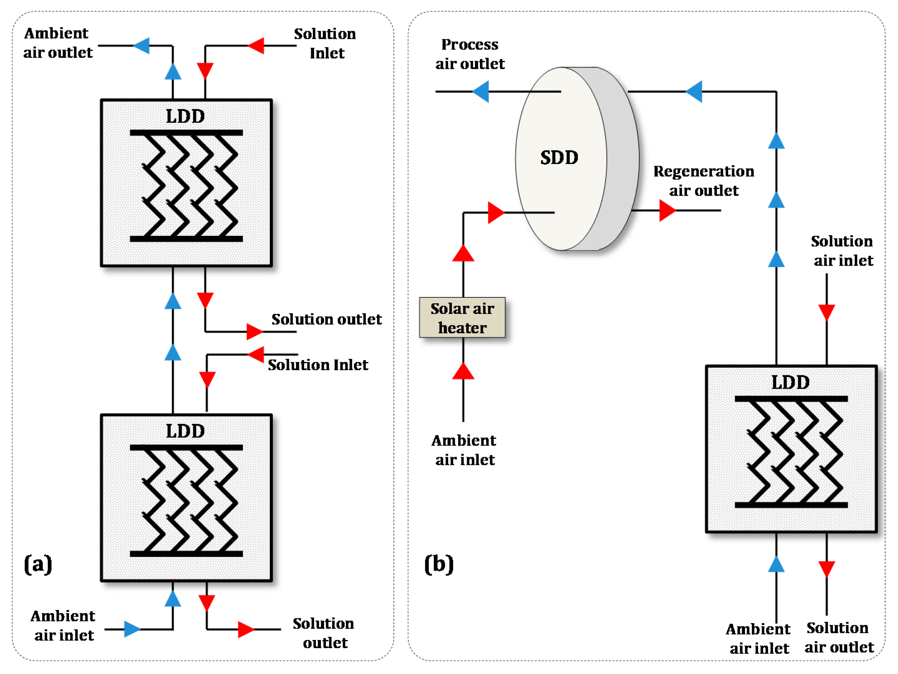
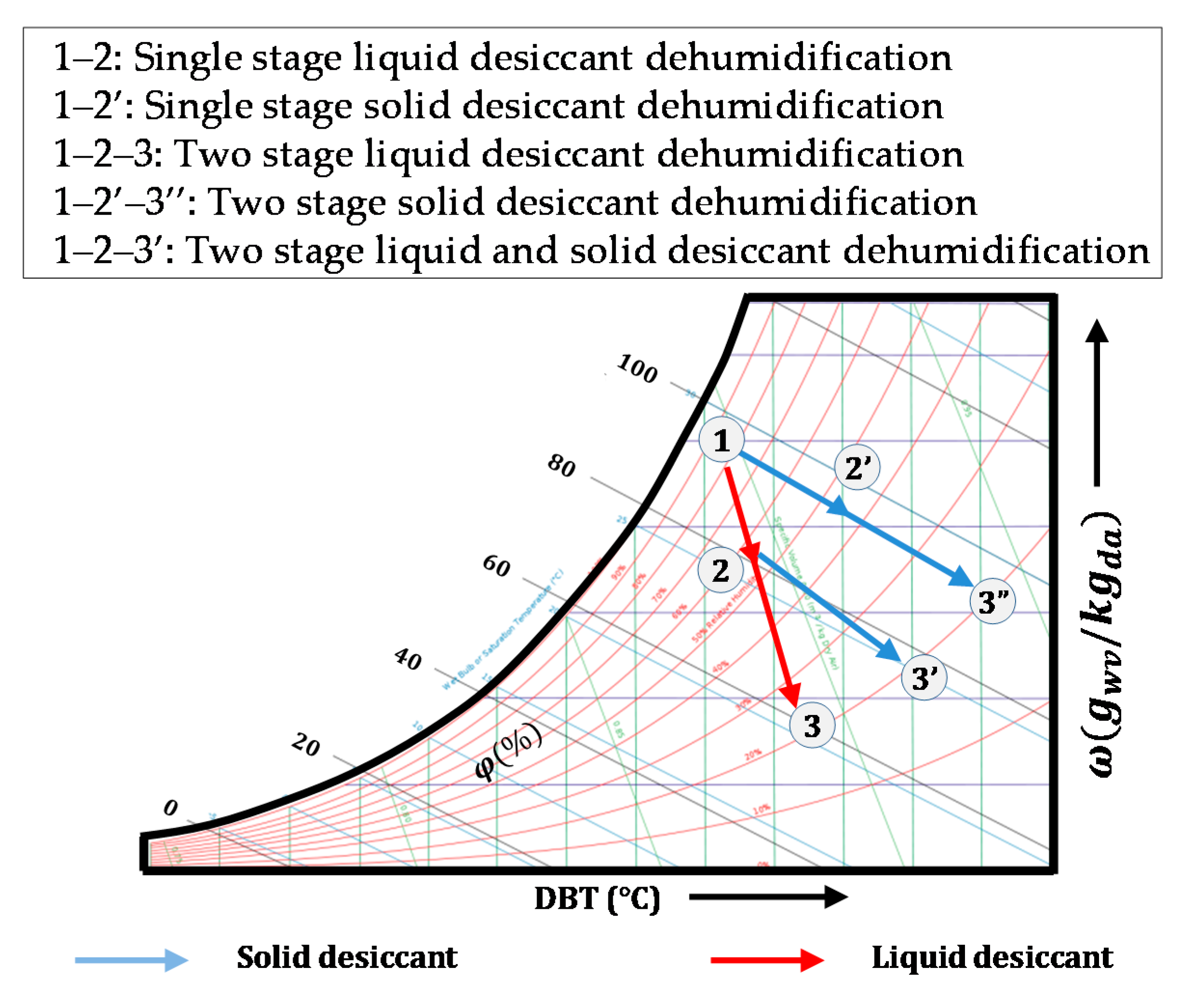
3. Demonstration of Systems

Demonstration of TLDD and CLSDD Systems

Figure 5 presents the TLDD system consisting of two liquid desiccant dehumidifiers and CLSDD system consisting of a liquid desiccant dehumidifier and a solid desiccant wheel. Initially, in both the TLDD and CLSDD systems, the desiccant solution and ambient air interacts in a counterflow direction and desorbs moisture to the desiccant solution. Later, the dehumidified air is further dehumidified in the TLDD system using a secondary liquid desiccant dehumidifier (Figure 5a). Whereas in the CLSDD system, the dehumidified air is further dehumidified using a solid desiccant wheel (Figure 5b). Thus, deep dehumidified ambient air comes out of both the CLSDD and the TLDD systems.

4. Results

In this section, the performance comparison among the SSDD, TSDD, SLDD, TLDD, and CLSDD systems for room air conditioning and deep drying applications is presented with reference to humid climates. Condensation rate and moisture removal efficiency are chosen as performance parameters for room air conditioning application, whereas the outlet air temperature is considered as a performance parameter for deep drying application. The operating parameters and their range chosen for the parametric analysis of the dehumidification systems are given in Table 1 and Table 2.

4.1. Room Air Conditioning Application

Desiccant dehumidification systems can be preferred in humid climatic conditions for maintaining the comfort conditions inside a building. Using moisture removal efficiency and condensation rate as the performance parameters, the performance of the SSDD, TSDD, SLDD, TLDD, and CLSDD systems are analysed.
For a designed dehumidification system capacity, effects of air inlet parameters (i.e., air flow rate, air inlet humidity ratio, and air inlet temperature) on condensation rate and moisture removal efficiency of the SSDD, TSDD, SLDD, TLDD, and CLSDD systems are shown in Figure 6.
For a given inlet condition (Table 1 and Table 2), Figure 6a,b shows the influence of air flow rate on condensation rate and moisture removal efficiency of the systems. From Figure 6a and Table 3, it is observed that with increase in air flow rate, condensation rate increases for all the desiccant dehumidification systems. This is due to the fact that as the condensation rate increases, rapid removal of moisture from the ambient air takes place at the air-desiccant interface by which air humidity ratio gradient decreases and maintains higher potential for transfer processes. It is also observed in Figure 6a that as the air flow rate increases from 0.9 kg/s to 1.7 kg/s, the condensation rate increases by 38%, 50%, 43.7%, 47.8%, and 50% for the SSDD, TSDD, SLDD, CLSDD, and TLDD systems, respectively. Further, it is found that at a given air flow rate of 1.7 kg/s, the condensation rate is about 8, 12, 16, 23, and 25 g/s and the moisture removal efficiency is about 25%, 35%, 44%, 61%, and 64% for the SSDD, TSDD, SLDD, CLSDD, and TLDD systems, respectively (see Figure 6a,b for detail). From this analysis, it is realized that the TLDD system performs better as compared to other dehumidification systems. From Figure 6b and Table 3, it is observed that with increase in air flow rate, there is an insignificant variation in moisture removal efficiency.
For a given inlet condition (Table 1 and Table 2), the effect of air inlet temperature on condensation rate and moisture removal efficiency is shown in Figure 6c,d. It can be seen from Figure 6c and Table 3 that with increase in air inlet temperature, the condensation rate decreases in all the dehumidification systems. It happens because, as the air inlet temperature increases, the temperature difference between the ambient air and the desiccant solution decreases. As a result, the vapor pressure difference decreases and the condensation rate also decreases. In addition, it is also found from Figure 6c that, with an increment in air inlet temperature from 28 to 35 °C, the decrement in condensation rate is about 33% for the TLDD system, 17% for the CLSDD system, 58% for the TSDD system, 27% for the SLDD system, and 20% for the SSDD system. It is observed from this analysis that the CLSDD system performs better than other desiccant dehumidification systems. It is due to less reduction in desiccant temperature in the liquid desiccant dehumidification system and deep moisture adsorption capabilities of the silica gel material.
It is also observed from Figure 6c that for a given temperature of 35 °C, the condensation rate for SSDD, TSDD, SLDD, TLDD, and CLSDD systems are about 5.7, 7.5, 7.8, 12, and 12.6 g/s, respectively. From this analysis, it is understood that for the given air temperature range (Table 1 and Table 2), the condensation rate is high for the CLSDD system and low for the SSDD system as compared to other desiccant dehumidification systems. The moisture removal efficiency is high at low air inlet temperature, which can be seen in Figure 6d and Table 3. It is because the desiccant material is cooled to a lower temperature at low air inlet temperature, thereby increasing the moisture transfer rate from air to desiccant material. Further Figure 6d shows that, as the air inlet temperature increases from 25 to 35 °C, the percentage decrements in SSDD, TSDD, SLDD, TLDD, and CLSDD systems are about 44%, 32%, 1%, 0.7% and 13%, respectively. From this analysis, it is understood that with increase in air inlet temperature, there is a significant decrease in moisture removal efficiency in the SSDD, TSDD, and CLSDD systems, and there is a marginal decrease in this efficiency for the TLDD and SLDD systems. This indicates that the sensible heat transfer rate is predominant at the air desiccant interface for the solid desiccant material as compared to the liquid desiccant material. Further, Figure 6d shows that for a given temperature of 25 and 35 °C, the moisture removal efficiencies are about 39% and 20% for the SSDD system, 57% and 36% for the TSDD system, 42% and 40% for the SLDD system, 60% and 59% for the TLDD system, and 67% and 58% for the CLSDD system, respectively. Thus, it is realized that the TLDD system performs well compared to other dehumidification systems.
For a given inlet condition presented in Table 1 and Table 2, the effect of air inlet humidity ratio on condensation rate is shown in Figure 6e,f. It is found from Figure 6e that for all dehumidification systems, the condensation rate increases with increase in air inlet humidity ratio. It can be explained by the fact that as the air inlet humidity ratio increases, the air vapour pressure increases. Hence, the potential for moisture removal from air increases. From Figure 6e, it is also observed that at high air inlet humidity ratio of 30 gwv/kgda, the condensation rate for SSDD, TSDD, SLDD, TLDD, and CLSDD systems are about 6.8, 10, 13.2, 19.6 and 18.8 g/s, respectively. From this investigation, it is observed that the SLDD, TLDD, and CLSDD systems exhibits higher condensation rate as compared to SSDD and TSDD systems, and liquid desiccant dehumidifier performs better compared to the solid desiccant wheel at higher air humidity ratio.
From Figure 6e, it is found that with an increase in air inlet humidity ratio from 20 to 30 gwv/kgda, condensation rate for the SSDD, TSDD, SLDD, TLDD, and CLSDD systems increases by 34%, 25%, 52%, 75%, and 56% respectively. From this analysis, it is understood that with an increase in air humidity ratio, the condensation rate in the TLDD system is more effective compared to other dehumidification systems.
From Figure 6f, it is observed that with increase in inlet air humidity ratio, moisture removal efficiency increases for the SLDD and TLDD systems, decreases for the SSDD and TSDD systems, and remains almost constant for the CLSDD system. This indicates that the moisture transfer capability variation is insignificant for the solid desiccant-based dehumidification system compared to the liquid desiccant-based dehumidification system, i.e., the variation in moisture removal rate for the solid desiccant material is negligible at higher air humidity ratios. From Figure 6f, it is also seen that as the air inlet humidity ratio increases from 20 to 30 gwv/kgda, moisture removal efficiency decreases by 24% and 28% for the SSDD and TSDD systems and increases by 17% and 20% for the SLDD and TLDD systems. Further, it is found that at air inlet humidity ratio of 30 gwv/kgda, the moisture removal efficiencies for the SSDD, TSDD, SLDD, CLSDD, and TLDD systems are 22%, 33%, 48%, 60% and 69%, respectively. From this analysis, it is concluded that the moisture removal efficiency is high for the TLDD system.
By investigating the influences of air inlet parameters, i.e., air flow rate, air inlet humidity ratio, and air inlet temperature on condensation rate and moisture removal efficiency, it has been concluded that the TLDD system is more effective for room air conditioning application in humid climates as compared to other desiccant dehumidification systems. Further, it has also been concluded that in humid climates, for improving the system performance all the dehumidification systems should operate at high air flow rate and low air inlet temperature.
It has been found that the TLDD system is more effective in room air conditioning application. Therefore, in this section for a designed dehumidification capacity of 25 kW and for a given range of operating parameters and inlet condition presented in Table 1 and Table 2, a profound numerical analysis on TLDD system is carried out by investigating the interactive effect of air inlet parameters on latent heat ratio, as shown in Figure 7. It is found that the latent heat ratio is high at high air flow rate and humidity ratio and at low air inlet temperature. This is due to rapid interaction of bulk air with the desiccant solution at the interface at high air flow rate, high water vapor content present in the ambient air at high humidity ratio, and high temperature difference between the ambient air and the desiccant at low air inlet temperature. Further, it is also observed that maximum latent heat ratio for the interactive effect of air inlet humidity ratio and temperature is 0.87, for the interactive effect of air flow rate and temperature is 0.81 and for the interactive effect of air inlet humidity ratio and flow rate is 0.83. From this analysis, it is realized that the interactive effect of air inlet humidity ratio and temperature has a higher impact on the performance of the TLDD system.

4.2. Drying Application

The drying process is essential for various applications, e.g., for storage of agricultural products, wood, timber, and dairy items. Conventionally, the solar dryers are used for drying these products. However, solar dryers may not be efficient in humid climates due to the high relative humidity (i.e., ranging from 70–90%) and due to low solar intensities (i.e., ranging from 100–500 W/m2).
It has been found in the literature that the thermally driven desiccant dehumidification systems can provide optimum performance in case of drying applications [25,26] as well as various associated agricultural applications [27,28,29,30]. Therefore, desiccant-based dehumidification system is investigated in this study to enhance the deep drying process in humid climates. For a designed dehumidification system capacity of 25 kW, the performance of SSDD, TSDD, SLDD, TLDD, and CLSDD systems are compared. Further, analysed the suitable desiccant dehumidification system for industrial deep drying processes and for drying the agricultural products below 70 °C. In order to analyse and compare the performance of aforementioned systems for deep drying application, dehumidified air outlet temperature is chosen as a key performance indicator.
Figure 8 and Table 3 present the effects of air inlet parameters, i.e., air flow rate, air inlet humidity ratio, and air inlet temperature on air outlet temperature of the abovementioned systems. It is observed from Figure 8a and Table 3 that for a given inlet condition (Table 1 and Table 2), with an increase in air inlet humidity ratio, the variation in air outlet temperature is negligible. This happens because as the air inlet humidity ratio increases, the moisture content present in the ambient air increases, but the air inlet temperature remains the same. As a result, there is an insignificant variation in sensible heat exchange occurring at the air desiccant interface. Further from Figure 8a, it is found that for a given inlet air humidity ratio of 30 gwv/kgda, the outlet air temperature of the SSDD, TSDD, SLDD, TLDD, and CLSDD systems are about 52, 64, 33, 31, and 48 °C, respectively. From this investigation, it is realized that the TSDD system has a higher outlet temperature, and the TLDD system has a lower outlet temperature as compared to other desiccant dehumidification systems.
The effect of air flow rate on the air outlet temperature of the SSDD, TSDD, SLDD, TLDD, and CLSDD systems is shown in Figure 8b and Table 3. It can be seen from Figure 8b that with increase in air flow rate for SLDD and TLDD systems, there is a marginal increase in air outlet temperature. This can be explained by the fact that as the air flow rate increases, the bulk air will interact with the desiccant solution due to rapid air flow, thus maintaining constant temperature gradient at the air desiccant interface, and ultimately, the air outlet temperature will increase. In this case, the temperature difference between the air and the desiccant solution is 3 °C (Ta > Ts) (Table 1 and Table 2). For that reason, there is a marginal increment in air outlet temperature. If the temperature difference between the air and the desiccant solution is high, then the variation of air flow rate will have a significant impact on air outlet temperature of the single-stage and two stage liquid desiccant dehumidification system.
It is also observed from Figure 8b that with increase in air flow rate, there is a significant decrease in air outlet temperature for the SSDD and TSDD systems. It is due to the fact that as the air flow rate increases, the moisture adsorption capability of solid desiccant material increases. Thus, the solid desiccant material latent heat dissipation capability increases, but the sensible heat dissipation capability and the thermal energy needed for regeneration of solid desiccant material remains constant. As a consequence, more amount of moisture is adsorbed, but the low amount of moisture is desorbed from the solid desiccant material. Therefore, the latent heat dissipation capability decreases, and the sensible heat exchange from the desiccant solution to the ambient air remains constant. Therefore, the air outlet temperature decreases for the SSDD and TSDD systems.
In the case of the CLSDD system, with increase in air flow rate, the air outlet temperature decreases (Figure 8b). From this analysis, it is understood that as the air flow rate increases, the heat and mass exchange processes across the solid desiccant wheel will have a significant impact on the air outlet temperature of the CLSDD system. For an air flow rate of 1.7 kg/s, the air outlet temperature is about 49, 62, 33, 32, and 47 °C for the SSDD, TSDD, SLDD, TLDD, and CLSDD systems, respectively (Figure 8b). From this investigation, it is observed that compared to other desiccant dehumidification systems, the SSDD and TLDD systems have higher and lower air outlet temperatures, respectively.
For the inlet condition presented in Table 1 and Table 2, Figure 8c and Table 3 show the influence of air inlet temperature on the air outlet temperature of the SSDD, TSDD, SLDD, TLDD, and CLSDD systems. The outlet air temperature increases for all the dehumidification systems with increase in the inlet air temperature. This may be explained by the fact that as the air inlet temperature increases, the sensible heat exchange between the desiccant solution and ambient air increases, but the latent heat exchange remains constant due to constant air humidity ratio. Hence, the air outlet temperature increases.
From Figure 8c, it is found that at an air inlet temperature of 25 °C, the outlet air temperature is higher for the CLSDD system as compared to the SSDD system. Further, it is also found that as the air outlet temperature crosses beyond 27 °C, the SSDD system temperature is higher as compared to the CLSDD system. This happens because for a given desiccant dehumidification system capacity, at low temperature (i.e., at 25 °C), the latent heat exchange between the air and the desiccant is more effective in SSDD system compared to CLSDD system. However, with increase in air inlet temperature, the latent heat dissipation capabilities of the CLSDD system will be higher than the SSDD system. It is due to the effective deep dehumidification process involved in the CLSDD system, i.e., ambient air desorbs more amount of moisture due to the combination of the liquid desiccant dehumidifier and solid desiccant wheel. Hence, at high temperatures, the SSDD system is more effective than the CLSDD system for deep drying application. As the air inlet temperature increases beyond 33 °C, the TLDD system exhibits higher air outlet temperature as compared to SLDD system. It is because the sensible heat exchange between the liquid desiccant and the ambient air is higher in case of TLDD system as compared to the SLDD system. This is due to the combination of two liquid desiccant dehumidifiers in the TLDD system, i.e., moisture absorption capability of liquid desiccant material is constant in both systems but in case of the TLDD system, as the ambient air enters into two liquid desiccant dehumidifiers connected in series (Figure 5a); therefore, the temperature change will be higher in the TLDD system compared to the SLDD system.
It is found that for an air inlet temperature of 34 °C, SSDD, TSDD, SLDD, TLDD, and CLSDD systems has air outlet temperature of 53, 67, 33, 34, and 50 °C, respectively. From this analysis, it is found that the TSDD system has a higher air outlet temperature, and the SLDD system has a lower air outlet temperature. Further, it is also found that an increase in air inlet temperature from 25 to 35 °C, the air outlet temperature increases by 6, 9, 4, 8, and 4 °C for the SSDD, TSDD, SLDD, TLDD, and CLSDD systems, respectively. From this investigation, it is observed that for an increase in air inlet temperature, the change in air outlet temperature is high for the TSDD system and low for the CLSDD and SLDD systems as compared to other desiccant dehumidification systems.
From Figure 8, it has been concluded that the TSDD system will be more effective in humid climatic conditions as compared to other desiccant dehumidification systems for deep drying of industrial processes and for low temperature drying of agricultural products. Further, for deep drying application, performance of the SSDD, TSDD, SLDD, TLDD, and CLSDD systems can be increased by operating at low air flow rate and high air inlet temperature.
Table 4 provides different drying applications based on air outlet temperature of the desiccant dehumidification systems. From this table, it can be observed that these systems possess a huge potential for drying application. It is relied from Table 4 that the desiccant dehumidification system can be chosen as an alternative for drying the agricultural products without losing its nutritional content. Moreover, in humid climates, depending upon the required air outlet temperature (as discussed in Table 4), these dehumidification systems can be selected as an alternative for drying clothes, for clay brick production, for preservation of dry fruits, etc.

4.3. Comparison for Room Air Conditioning and Drying Applications

The performance comparison is made for the SSDD, TSDD, SLDD, TLDD, and CLSDD systems by choosing the maximum and minimum air inlet parameters. The obtained results are presented in Table 5. The comparison of heating and dehumidification processes for the SSDD, TSDD, SLDD, TLDD, and CLSDD systems is depicted in the psychrometric chart shown in Figure 9. Figure 9 and Table 5 prove that a solid desiccant dehumidification system has higher air outlet temperature and lower moisture removal capacity as compared to the liquid desiccant dehumidification system.
It is also observed from Table 5 that the SLDD and TLDD systems are more feasible for room air conditioning application. However, for deep drying application, SSDD, TSDD, and CLSDD systems are more suitable. It is also found that the SSDD and CLSDD systems can be used for low temperature deep drying application (30 °C < Ta < 50 °C), and TSDD system can be used for high temperature deep drying application (50 °C < Ta < 70 °C). Further, it is also observed that for a given dehumidification system capacity, to improve the moisture removal rate, the CSLD system is better as compared to the SSDD system in low temperature deep drying application. Whereas, in a room air conditioning application, the TLDD system is found to be better compared to the SLDD system. Further, the summary of present investigation for performance assessment of solid and liquid desiccant dehumidification systems for room air conditioning and deep drying applications is depicted in Figure 10.

5. Discussion

From the results, it was found that the TLDD system is a more appropriate choice for room air conditioning as compared to other studied options, i.e., SSDD, SLDD, TSDD, and CLSDD. The SSDD and CLSDD systems are appropriate for relatively lower regeneration temperature (i.e., 30 to 50 °C) deep dehumidification applications, whereas the TSDD system is appropriate for relatively higher regeneration temperature (i.e., 50 to 70 °C) deep dehumidification applications. It was found that performance of the studied systems (i.e., SSDD, TSDD, SLDD, TLDD, and CLSDD) is positively impacted by increasing the air flow rate and humidity ratio, and at lower air inlet temperature for room air conditioning application. In other words, studied systems are best suitable for higher humidity regions that receive heavy annual rainfall. For deep drying application, the studied systems (i.e., SSDD, TSDD, SLDD, TLDD, and CLSDD) performed relatively better at lower air flow rate and higher air inlet temperature. In terms of the benefits and advantages of the conducted study, desiccant dehumidification systems can be chosen as an alternative for industrial deep drying processes and for low temperature drying of agricultural products (below regeneration temperature 70 °C) in humid climatic conditions. Finally, from the viewpoint of research highlights, the results of the study indicated that interactive effects of humidity ratio and temperature have an impact on the performance of the studied liquid and solid desiccant dehumidification systems.

Environment and Sustainability Issues

The liquid desiccants used in SLDD, TLDD, and CLSDD systems are corrosive in nature and may impact the environment and health hazardous if the liquid desiccants are exposed to the drying/ air-conditioned space, whereas solid desiccants used in the SSDD, TSDD, and CLSDD systems are more environmental friendly. The sustainability/life expectancy of both the solid and liquid desiccant-based dehumidification systems are about 10–15 years after that the performance of these systems gets deteriorated. Further, the limitations of the liquid desiccant dehumidification system are that a small portion of liquid desiccant is evaporated into the atmosphere, and there is a requirement of liquid desiccant makeup in the system for each circulation of desiccant solution, whereas in the case of solid desiccant dehumidification system, the system applicability/utilization for large-scale capacities beyond 50 kW capacity is a limitation due to desiccant wheel structure.

6. Conclusions

In this paper, the performances of the SSDD, TSDD, SLDD, TLDD, and CLSDD systems are analysed for a designed dehumidification system capacity of 25 kW. In order to investigate the simultaneous heat and mass transfer processes occurring in a liquid desiccant dehumidifier and a solid desiccant wheel, LiCl and RD silica gel are chosen as liquid and solid desiccant materials, respectively. Condensation rate and moisture removal efficiency are chosen as the performance parameters for room air conditioning application, and air outlet temperature is chosen as a performance parameter for deep drying application. For a given range of operating parameters, the influences of air inlet parameters, i.e., air inlet temperature, air flow rate, and air inlet humidity ratio on condensation rate, moisture removal efficiency, and air outlet temperature are studied in detail and following conclusions are made:
  • For a designed dehumidification system capacity, the TLDD is more suitable for room air conditioning application compared to other dehumidification systems.
  • The SSDD and CLSDD are suitable for low temperature deep drying application, i.e., from 30 to 50 °C. The TSDD system is suitable for high temperature deep drying application, i.e., from 50 to 70 °C.
  • Performances of the SSDD, TSDD, SLDD, TLDD, and CLSDD systems are enhanced at high air flow rate and humidity ratio and at low air inlet temperature for room air conditioning.
  • In deep drying application, the performance of the SSDD, TSDD, SLDD, TLDD, and CLSDD systems are better at low air flow rate and high air inlet temperature.
  • The interactive effect of air inlet parameters on latent heat ratio of the TLDD system is investigated. From this investigation, it is observed that interactive effects of air inlet humidity ratio and temperature have a greater impact on the performance of the TLDD system.
  • In humid climatic conditions, desiccant dehumidification system can be chosen as an alternative for industrial deep drying processes and for low temperature (below 70 °C) drying of agricultural products.
The dehumidification system selection methodology described in the present study can be used as a reference tool for selection of dehumidification system for various application.

Author Contributions

Conceptualization: B.K.N.; data curation: M.J.; formal analysis: B.K.N., M.J., P.M., and M.S.; funding acquisition: B.K.N., M.S., and R.R.S.; investigation: B.K.N., M.J., M.S., and R.R.S.; methodology: B.K.N., P.M., and M.S.; project administration: B.K.N., P.M., and M.S.; resources: T.M.; software: M.J. and M.S.; supervision: P.M. and T.M.; validation: M.J. and T.M.; visualization: M.J., T.M., R.R.S., and H.A.; writing—original draft: B.K.N. and M.J.; Writing—review, final editing, and graphics improvement: P.M., M.S., T.M., R.R.S., and H.A. All authors have read and agreed to the published version of the manuscript.

Funding

This research received no external funding.

Acknowledgments

First author acknowledges the funding received from Science and Engineering Research Board (SERB-ITS Travel Grant (ITS/Off529/2017–18)) for attending the international conference–ISHPC 2017, held at Waseda University (Japan). The authors acknowledge the financial support by the Open Access Publication Fund of the Leibniz Association, Germany, the editorial supports from Adaptive AgroTech Consultancy International, and the administrative supports from Benjamin Mahns at the Leibniz Institute for Agricultural Engineering and Bioeconomy in Potsdam, Germany.

Conflicts of Interest

The authors declare no conflict of interest.

Nomenclature

a s Specific surface area per unit volume (m2/m3)
α h heat transfer coefficient along liquid desiccant dehumidifier (W/m2K)
α m mass transfer coefficient along liquid desiccant dehumidifier (kg/m2s)
ζ T logarithmic function of thermal effectiveness
ζ m logarithmic function of moisture effectiveness
τ h function of heat transfer coefficient and air mass flux
τ m function of mass transfer coefficient and air mass flux
AwArea of solid desiccant wheel (m2)
CLSDDTwo-stage combined liquid and solid desiccant dehumidification system
CpSpecific heat at constant pressure (kJ/kg–K)
GMass flux or flow rate per unit cross sectional area (kg/m2–s)
henthalpy (kJ/kg)
KmThermal conductivity of solid desiccant material (W/m–K)
LDDLiquid desiccant dehumidifier
LeLewis number
Mass flow rate of ambient air (kg/s)
NTUNo. of mass transfer units
PPerimeter (m)
QlatLatent heat exchange (kW)
QoOverall heat exchange (kW)
QsenSensible heat exchange (kW)
R. H.Relative humidity (%)
SDDSolid desiccant dehumidifier
SLDDSingle-stage liquid desiccant dehumidification system
SSDDSingle-stage solid desiccant dehumidification system
TTemperature (°C)
TLDDTwo-stage liquid desiccant dehumidification system
TSDDTwo-stage solid desiccant dehumidification system
vVelocity of ambint air (m/s)
XwWater content of desiccant material (kgwv/kgdes.)
zHeight (m)
ζlatent heat ratio
ρdensity (kg/m3)
ϕdrelative humidity at the solid desiccant wall (%)
ϕhheat transfer coefficient across solid desiccant wheel (W/m2K)
ϕmmass transfer coefficient across solid desiccant wheel (kg/m2s)
ϕrequilibrium relative humidity (%)
χheat of adsorption (kJ/kg)
mass diffusion coefficient (m2/s)
β desiccant concentration (kgdes./kgsol.)
γ ratio of mass flux of working fluid and air
δ latent heat of vaporization (kJ/kg)
λ evaporation/condensation rate (g/m2s)
ξ effectiveness
ω humidity ratio (kgv/kgda)
Subscripts
aair
atmatmospheric
avgaverage
dadry air
desdesiccant
eequilibrium
iinlet
mmoisture
ooutlet
pprocess air
rregeneration
ssolution
Superscripts
svsaturated water vapor
Tthermal
vwater vapor
wwater

Appendix A

In the present study, a comparison between SSDD, TSDD, SLDD, TLDD, and CLSDD is made for 25 kW designed dehumidification system capacity, using the developed thermal models reported in the literature [6,19]. Additionally, in this study, no experimental comparison is carried out.
The thermo-physical properties of ambient air, saturated water vapor, and desiccant material are taken from Chung et al. [6] and Ge et al. [8]. The equilibrium relative humidity (ϕr) on the surface of the RD silica gel is calculated using Equation (A1).
ϕ r = 0.0078 0.05759 X w + 24.16554 X w 2 124.78 X w 3 + 204.226 X w 4
The saturated water vapor pressure (Psv) is obtained from the Antonine [7] equation, which is available as a MATLAB function [31] and is represented in Equation (A2) as:
P sv = exp ( 23.196 3816.44 T s 46.13 )
Humidity ratio of the air existing in equilibrium with the desiccant (ωs) is obtained ( ϕ d = ϕ r ) from Equation (A3) given in literature as [7]:
ω s = 0.62218 ϕ d P atm P sv ϕ r
The heat and mass transfer coefficients across the solid desiccant wheel (ϕh and ϕm) are determined using Equations (A4) and (A5), accordingly [7].
ϕ h = K m P 4 A w
ϕ m = ρ a Sh y P 4 A w ;   ( Nu y = Sh y )
where Nu is a Nusselt number, Sh is Sherwood number, Km is thermal conductivity (W/m-K) of solid desiccant material and ‘Ʊ’ is mass diffusion coefficient (m2/s).

References

  1. Jeong, J.; Yamaguchi, S.; Saito, K.; Kawai, S. Performance analysis of desiccant dehumidification systems driven by low-grade heat source. Int. J. Refrig. 2011, 34, 928–945. [Google Scholar] [CrossRef]
  2. Jia, C.X.; Dai, Y.J.; Wu, J.Y.; Wang, R.Z. Experimental comparison of two honeycombed desiccant wheels fabricated with silica gel and composite desiccant material. Energy Convers. Manag. 2006, 47, 2523–2534. [Google Scholar] [CrossRef]
  3. Ge, T.S.; Li, Y.; Wang, R.Z.; Dai, Y.J. Experimental study on a two-stage rotary desiccant cooling system. Int. J. Refrig. 2009, 32, 498–508. [Google Scholar] [CrossRef]
  4. Abd-Elrahman, W.R.; Hamed, A.M.; El-Emam, S.H.; Awad, M.M. Experimental investigation on the performance of radial flow desiccant bed using activated alumina. Appl. Therm. Eng. 2011, 31, 2709–2715. [Google Scholar] [CrossRef]
  5. Tu, R.; Liu, X.-H.; Jiang, Y. Performance analysis of a two-stage desiccant cooling system. Appl. Energy 2014, 113, 1562–1574. [Google Scholar] [CrossRef]
  6. Chung, J.D.; Lee, D.-Y.; Yoon, S.M. Optimization of desiccant wheel speed and area ratio of regeneration to dehumidification as a function of regeneration temperature. Sol. Energy 2009, 83, 625–635. [Google Scholar] [CrossRef]
  7. Zhang, X.J.; Dai, Y.J.; Wang, R.Z. A simulation study of heat and mass transfer in a honeycombed rotary desiccant dehumidifier. Appl. Therm. Eng. 2003, 23, 989–1003. [Google Scholar] [CrossRef]
  8. Ge, T.S.; Li, Y.; Wang, R.Z.; Dai, Y.J. A review of the mathematical models for predicting rotary desiccant wheel. Renew. Sustain. Energy Rev. 2008, 12, 1485–1528. [Google Scholar] [CrossRef]
  9. Dai, Y.; Li, X.; Wang, R. Theoretical analysis and case study on solar driven two-stage rotary desiccant cooling system combined with geothermal heat pump. Energy Procedia 2015, 70, 418–426. [Google Scholar] [CrossRef] [Green Version]
  10. La, D.; Dai, Y.; Li, Y.; Ge, T.; Wang, R. Case study and theoretical analysis of a solar driven two-stage rotary desiccant cooling system assisted by vapor compression air-conditioning. Sol. Energy 2011, 85, 2997–3009. [Google Scholar] [CrossRef]
  11. Yadav, A.; Yadav, L. Comparative performance of desiccant wheel with effective and ordinary regeneration sector using mathematical model. Heat Mass Transf. 2014, 50, 1465–1478. [Google Scholar] [CrossRef] [Green Version]
  12. Sultan, M.; Miyazaki, T.; Koyama, S. Optimization of adsorption isotherm types for desiccant air-conditioning applications. Renew. Energy 2018, 121, 441–450. [Google Scholar] [CrossRef]
  13. Sultan, M.; El-Sharkawy, I.I.; Miyazaki, T.; Saha, B.B.; Koyama, S.; Maruyama, T.; Maeda, S.; Nakamura, T. Water vapor sorption kinetics of polymer based sorbents: Theory and experiments. Appl. Therm. Eng. 2016, 106, 192–202. [Google Scholar] [CrossRef]
  14. Sultan, M.; El-sharkawy, I.I.; Miyazaki, T.; Baran, B.; Koyama, S. An overview of solid desiccant dehumidi fi cation and air conditioning systems. Renew. Sustain. Energy Rev. 2015, 46, 16–29. [Google Scholar] [CrossRef]
  15. Naik, B.K.; Muthukumar, P.; Kumar, P.S. A novel finite difference model coupled with recursive algorithm for analyzing heat and mass transfer processes in a cross flow dehumidifier/regenerator. Int. J. Therm. Sci. 2018, 131, 1–13. [Google Scholar] [CrossRef]
  16. Fumo, N.; Goswami, D.Y. Study of an aqueous lithium chloride desiccant system: Air dehumidification and desiccant regeneration. Sol. Energy 2002, 72, 351–361. [Google Scholar] [CrossRef]
  17. Varela, R.J.; Giannetti, N.; Yamaguchi, S.; Saito, K.; Wang, X.-M.; Nakayama, H. Experimental investigation of the wetting characteristics of an aqueous ionic liquid solution on an aluminum fin-tube substrate. Int. J. Refrig. 2018, 88, 472–482. [Google Scholar] [CrossRef]
  18. Gao, W.Z.; Liu, J.H.; Cheng, Y.P.; Zhang, X.L. Experimental investigation on the heat and mass transfer between air and liquid desiccant in a cross-flow dehumidifier. Renew. Energy 2012, 37, 117–123. [Google Scholar] [CrossRef]
  19. Naik, B.K.; Muthukumar, P.; Bhattacharyya, C. Thermal modelling and parametric investigations on coupled heat and mass transfer processes occurred in a packed tower. Heat Mass Transf. 2019, 55, 627–644. [Google Scholar] [CrossRef]
  20. Longo, G.A.; Gasparella, A. Experimental and theoretical analysis of heat and mass transfer in a packed column dehumidifier/regenerator with liquid desiccant. Int. J. Heat Mass Transf. 2005, 48, 5240–5254. [Google Scholar] [CrossRef]
  21. Koronaki, I.P.; Christodoulaki, R.I.; Papaefthimiou, V.D.; Rogdakis, E.D. Thermodynamic analysis of a counter flow adiabatic dehumidifier with different liquid desiccant materials. Appl. Therm. Eng. 2013, 50, 361–373. [Google Scholar] [CrossRef]
  22. Naik, B.K.; Muthukumar, P. Experimental investigation and parametric studies on structured packing chamber based liquid desiccant dehumidification and regeneration systems. Build. Environ. 2019, 149, 330–348. [Google Scholar] [CrossRef]
  23. Naik, B.K.; Muthukumar, P. Energy, entransy and exergy analyses of a liquid desiccant regenerator. Int. J. Refrig. 2019, 105, 80–91. [Google Scholar] [CrossRef]
  24. Naik, B.K.; Muthukumar, P. Parametric and Performance Investigations on Novel Multipurpose Liquid Desiccant Drying/Desalination System. Heat Transfer Eng. 2020, 1–17. [Google Scholar] [CrossRef]
  25. Mahmood, M.H.; Sultan, M.; Miyazaki, T. Solid desiccant dehumidification-based air-conditioning system for agricultural storage application: Theory and experiments. Proc. Inst. Mech. Eng. Part A J. Power Energy 2020, 234, 534–547. [Google Scholar] [CrossRef]
  26. Hanif, S.; Sultan, M.; Miyazaki, T.; Koyama, S. Investigation of energy-efficient solid desiccant system for the drying of wheat grains. Int. J. Agric. Biol. Eng. 2019, 12, 221–228. [Google Scholar]
  27. Sultan, M.; Miyazaki, T.; Saha, B.B.; Koyama, S. Steady-state investigation of water vapor adsorption for thermally driven adsorption based greenhouse air-conditioning system. Renew. Energy 2016, 86, 785–795. [Google Scholar] [CrossRef]
  28. Sultan, M.; Miyazaki, T.; Koyama, S.; Khan, Z.M. Performance evaluation of hydrophilic organic polymer sorbents for desiccant air-conditioning applications. Adsorpt. Sci. Technol. 2018, 36, 311–326. [Google Scholar] [CrossRef] [Green Version]
  29. Rezvani, S.M.; Abyaneh, H.Z.; Shamshiri, R.R.; Balasundram, S.K.; Dworak, V.; Goodarzi, M.; Sultan, M.; Mahns, B. IoT-Based Sensor Data Fusion for Determining Optimality Degrees of Microclimate Parameters in Commercial Greenhouse Production of Tomato. Sensors 2020, 20, 6474. [Google Scholar] [CrossRef]
  30. Shamshiri, R.R.; Bojic, I.; van Henten, E.; Balasundram, S.K.; Dworak, V.; Sultan, M.; Weltzien, C. Model-based evaluation of greenhouse microclimate using IoT-Sensor data fusion for energy efficient crop production. J. Clean. Prod. 2020, 263, 121303. [Google Scholar] [CrossRef]
  31. Shamshiri, R.R.; Che Man, H.; Zakaria, A.J.; Beveren, P.V.; Wan Ismail, W.I.; Ahmad, D. Membership function model for defining optimality of vapor pressure deficit in closed-field cultivation of tomato. Acta Hortic. 2017, 1152, 281–290. [Google Scholar] [CrossRef]
Figure 1. Schematic of (a) single-stage solid desiccant dehumidification (SSDD) system, (b) single-stage liquid desiccant dehumidification (SLDD) system, and (c) two-stage solid desiccant dehumidification (TSDD) system.
Sustainability 12 10582 g001
Figure 2. Heat and mass balance along the counterflow liquid desiccant dehumidifier.
Sustainability 12 10582 g002
Figure 3. Schematic representation of the computational domain and flow channel across the solid desiccant wheel.
Sustainability 12 10582 g003
Figure 4. Influence of dehumidifier NTU on condensation rate and air temperature change for single-stage liquid desiccant dehumidification system.
Sustainability 12 10582 g004
Figure 5. Schematic of (a) two-stage liquid desiccant dehumidification system, and (b) two-stage combined liquid and solid desiccant dehumidification systems.
Sustainability 12 10582 g005
Figure 6. Effect of air inlet (a) flow rate on condensation rate, (b) flow rate on moisture removal efficiency, (c) temperature on condensation rate, (d) temperature on moisture removal efficiency, (e) humidity ratio on condensation rate, and (f) humidity ratio on moisture removal efficiency; for SSDD, TSDD, SLDD, TLDD, and CLSDD systems.
Sustainability 12 10582 g006
Figure 7. Interactive effect of air inlet (a) temperature and humidity ratio on latent heat ratio, (b) temperature and flow rate on latent heat ratio, and (c) humidity ratio and flow rate on latent heat ratio; for two-stage liquid desiccant dehumidification system.
Sustainability 12 10582 g007
Figure 8. Effect of air inlet (a) humidity ratio on air outlet temperature, (b) flow rate on air outlet temperature, and (c) temperature on air outlet temperature; for all the SSDD, TSDD, SLDD, TLDD and CLSDD systems.
Sustainability 12 10582 g008
Figure 9. Heating and dehumidification processes shown in the psychrometric chart for all the single or two-stage liquid/solid/liquid and solid desiccant dehumidification system.
Sustainability 12 10582 g009
Figure 10. Summary of present investigation for room air-conditioning and drying applications.
Sustainability 12 10582 g010
Table 1. Operating parameters and their range is chosen for the parametric analysis.
Parameters Operating RangeReference Values
Liquid DesiccantSolid DesiccantLiquid DesiccantSolid Desiccant
Desiccant MaterialLiCl–H2ORD Silica gelLiCl–H2ORD Silica gel
Desiccant Wheel revolutions per hour (RPH)--24
Regeneration Temperature (°C)--90
Air Inlet Temperature (°C)28–353535
Solution Inlet Temperature (°C)-30-
Solution Concentration (kgLiCl/kgsol.)-40-
Solution Flow Rate (kg/s)-2-
Relative Humidity (R.H.) (%)57–857575
Air Flow Rate (kg/s)0.9–1.711
Air Humidity Ratio (gwv/kgda)20 (Ta −28 °C & R.H. −57%) −30 (Ta −35 °C & R.H. −85%)26.3 (Ta −33 °C & R.H. −75%)26.3 (Ta −35 °C & R.H. −75%)
Table 2. Specifications of the solid and liquid desiccant dehumidification systems.
SpecificationsLiquid Desiccant DehumidifierSolid Desiccant Dehumidifier
Regeneration Area-25% of the desiccant wheel area
Lewis Number 1-
Desiccant Wheel Diameter (m)-0.7
Desiccant Wheel Length (m)-0.2
Area Ratio (Ar/Ap)-1/3
Packed Tower Height (m) 0.6-
Dehumidification System Capacity 25 kW
Table 3. Effects of air inlet parameters on condensation rate and moisture removal efficiency (Figure 6).
Air Inlet Parameters
Air Flow Rate
(kg/s) ( Sustainability 12 10582 i001)
Air Humidity Ratio
(gwv/kgda) ( Sustainability 12 10582 i002)
Air Temperature
(°C) ( Sustainability 12 10582 i003)
Range0.9 (kg/s)–1.7 (kg/s)20 (gwv/kgda)–30 (gwv/kgda)28 (°C)–35 (°C)
Condensation Rate (g/s)
Single–Stage LDS Sustainability 12 10582 i004 Sustainability 12 10582 i005 Sustainability 12 10582 i006
Two–Stage LDS Sustainability 12 10582 i007 Sustainability 12 10582 i008 Sustainability 12 10582 i009
Single–Stage SDS Sustainability 12 10582 i010 Sustainability 12 10582 i011 Sustainability 12 10582 i012
Two–Stage SDS Sustainability 12 10582 i013 Sustainability 12 10582 i014 Sustainability 12 10582 i015
Two–Stage LSDS Sustainability 12 10582 i016 Sustainability 12 10582 i017 Sustainability 12 10582 i018
Moisture Removal Efficiency (%)
Single–Stage LDS Sustainability 12 10582 i019 Sustainability 12 10582 i020 Sustainability 12 10582 i021
Two–Stage LDS Sustainability 12 10582 i022 Sustainability 12 10582 i023 Sustainability 12 10582 i024
Single–Stage SDS Sustainability 12 10582 i025 Sustainability 12 10582 i026 Sustainability 12 10582 i027
Two–Stage SDS Sustainability 12 10582 i028 Sustainability 12 10582 i029 Sustainability 12 10582 i030
Two–Stage LSDS Sustainability 12 10582 i031 Sustainability 12 10582 i032 Sustainability 12 10582 i033
Air Outlet Temperature (°C)
Single–Stage LDS Sustainability 12 10582 i034 Sustainability 12 10582 i035 Sustainability 12 10582 i036
Two–Stage LDS Sustainability 12 10582 i037 Sustainability 12 10582 i038 Sustainability 12 10582 i039
Single–Stage SDS Sustainability 12 10582 i040 Sustainability 12 10582 i041 Sustainability 12 10582 i042
Two–Stage SDS Sustainability 12 10582 i043 Sustainability 12 10582 i044 Sustainability 12 10582 i045
Two–Stage LSDS Sustainability 12 10582 i046 Sustainability 12 10582 i047 Sustainability 12 10582 i048
Notes: Sustainability 12 10582 i049—Increment; Sustainability 12 10582 i050—Decrement; Sustainability 12 10582 i051—Intermediate (no change).
Table 4. List of various drying applications depending upon the air outlet temperature of the SSDD, TSDD, SLDD, TLDD, and CLSDD systems.
Sl. No.Type of Dehumidification SystemAir Outlet Temperature (°C)Application
1.SSDD48–53For laundry application and for drying agricultural products like Paddy, wheat, corn, etc.
2.TSDD59–65 For Clay brick production and drying vegetables like green chilli, red chilli, capsicum, etc.
3.SLDD30–35 Preserving fruits like Apple, tomato, grape, etc. and for drying vegetables like carrot, cabbage, peas, etc.
4.TLDD30–33 Agricultural and livestock applications
5.CLSDD44–50 For drying clothes and for drying dry fruits like cashew, pista, fig, etc.
Table 5. Summary of performances of single or two-stage liquid/solid/liquid and solid desiccant dehumidification systems at different inlet conditions.
Case 1: Single-Stage Liquid Desiccant Dehumidification System
Inlet ParametersOutlet Parameters
Air Flow Rate (kg/s)Air Temperature (°C)Relative Humidity (%)Condensation Rate (g/s)Air Outlet Temperature (°C)
128574.930
128858.930.4
1355713.733.6
135858.133.1
1.728578.230.4
1.7288514.831
1.7355722.434.6
1.7358513.533.7
Case 2: Single-Stage Solid Desiccant Dehumidification System
Inlet parametersOutlet Parameters
Air Flow Rate (kg/s)Air Temperature (°C)Relative Humidity (%)Condensation Rate (g/s)Air Outlet Temperature (°C)
128574.748.1
128856.048.9
135579.753.4
135855.252.9
1.728578.345.6
1.7288510.147.4
1.7355710.052.5
1.735858.751.4
Case 3: Two-Stage Liquid Desiccant Dehumidification System
Inlet ParametersOutlet Parameters
Air Flow Rate (kg/s)Air Temperature (°C)Relative Humidity (%)Condensation Rate (g/s)Air Outlet Temperature (°C)
128577.130.2
1288512.930.6
1355719.832.2
1358511.831.8
1.7285711.930.5
1.7288521.631.2
1.7355732.933.2
1.7358519.732.4
Case 4: Two-Stage Solid Desiccant Dehumidification System
Inlet ParametersOutlet Parameters
Air Flow rate (kg/s)Air Temperature (°C)Relative Humidity (%)Condensation Rate (g/s)Air Outlet Temperature (°C)
128577.459.7
128858.961.1
1355712.464.3
135857.864.1
1.7285712.155.5
1.7288514.958.4
1.7355715.563.4
1.7358512.961.2
Case 5: Two-Stage Liquid and Solid Desiccant Dehumidification System
Inlet ParametersOutlet Parameters
Air Flow Rate (kg/s)Air Temperature (°C)Relative Humidity (%)Condensation Rate (g/s)Air Outlet Temperature (°C)
128575.846.9
128859.047.3
1355721.949.6
1358514.449.2
1.728579.344.6
1.7288514.645.5
1.7355736.648.9
1.7358533.847.5
Publisher’s Note: MDPI stays neutral with regard to jurisdictional claims in published maps and institutional affiliations.

