1. Introduction
Humanity faces an urgent need for an alternative sustainable cooling source that would be environmentally friendly and easily available [
1]. Since 2015, the total amount of electricity consumed globally in the refrigeration sector has increased by 3%, reaching 20% in 2019 [
2,
3]. The amount of refrigeration systems, heat pumps and air conditioners installed in residential and commercial buildings increased by 2 billion during the same time, reaching a total of 5 billion. The International Energy Agency (IEA) predicts a further increase in the number of installed cooling devices with a corresponding rise in electrical consumption to operate them [
4]. Moreover, the European Commission set the long-term targets for reducing the emission of greenhouse gases and keeping the annual global temperature rise below 2 °C [
5,
6,
7]. In order to meet these goals, a substantial amount of research efforts has been devoted to developing new refrigerants for the conventional vapour compression cycle (CVCC) that would be more eco-friendly. In total, 35 new refrigerants, e.g., HCC-1130(E) and HFO-1132a, have been reported since the 2014 Refrigeration, Air Conditioning and Heat Pumps Technical Options Committee (RTOC) Assessment Report was published [
8]. The latter refrigerant has a boiling point of −86.7 °C and is suitable for cryogenic applications [
8]. Despite the fact that these refrigerants do not contribute, or contribute less, to greenhouse gasses emission and ozone layer depletion, they are less efficient in CVCC, and/or are flammable and/or toxic.
Another approach to solve the problem of ever-increasing energy demand is the development of alternative cooling technologies. The US Department of Energy (DOE) has summarised and evaluated all not-in-kind cooling technologies that are alternatives to CVCC [
9], and elastocaloric cooling was listed as the most promising alternative technology [
9]. The elastocaloric effect (eCE), which is the foundation of elastocaloric cooling, is observed in shape memory alloys (SMA), such as near-equiatomic Ni-Ti, Cu-Zn-A, and others [
10,
11], as well as in polymers such as natural rubber [
12]. The eCE is the thermal response of the active SMA material to the applied uniaxial stress [
13], i.e., cyclical tension or compression.
In principle, the eCE could be seen as an analogy to the magnetocaloric effect (MCE), where the external stimulus triggering the temperature rise inside the material is a magnetic field [
14,
15,
16]. The elastocaloric effect as well as the MCE are evaluated in terms of adiabatic temperature change, Δ
Tad, and isothermal entropy change, Δ
siso. The potential for heat transfer between the active material and the heat transfer fluid is quantified by Δ
Tad, while the capability of the active material to establish a high cooling power is measured by Δ
siso [
1]. Very recently, a (Ni
50Mn
50−xTi
x)
99.8B
0.2 alloy exhibiting colossal elastocaloric properties has been developed [
17]. This alloy demonstrates a superior reproducible adiabatic temperature change, Δ
Tad, of 31.5 K, and an isothermal entropy change, Δ
siso, of 45 J kg
−1 K
−1, compared to using thin wires of a benchmark material Ni-Ti which provides Δ
Tad = 25 K and Δ
siso = 35 J kg
−1 K
−1 [
10]. However, (Ni
50Mn
50−xTi
x)
99.8B
0.2 has not been tested in an elastocaloric device and there is no available information about its functional and structural fatigue or machinability.
Elastocaloric cooling is an attractive alternative for cooling/heat pumping applications due to its environmental friendliness [
18,
19]. Here, a solid material, i.e., an elastocaloric material, is shaped into a porous regenerator and is used as a refrigerant instead of hazardous gasses. A water-based heat transfer fluid is used for heat transfer from/to the active material to/from heat sink/source [
20]. However, there are many engineering challenges that should be solved before this technology can be competitive with CVCC. For example, an elastocaloric regenerator must provide a large cooling power at a sufficiently high coefficient of performance (
COP), and at the same time have sufficient fatigue resistance to withstand multiple mechanical (un)loading cycles. From magnetocaloric cooling, it was learned that the geometry of an active permeable regenerator significantly affects the efficiency of the cooling process [
21,
22,
23]. The SMA can be loaded in tension or compression [
12,
24]. The most frequently tested loading condition is tension [
13,
25,
26,
27,
28,
29,
30], because it enables a larger cooling effect compared to loading in compression. This is due to the higher available surface-to-volume ratio of the regenerator [
12,
26]. On the other hand, the fatigue resistance of the regenerator is higher under compression conditions [
12,
20,
31,
32]. It is estimated that a successful eCE regenerator should withstand more than 10
8 operational cycles [
33], and provide a system temperature span of at least 40 K [
20], both of which are challenging. Despite the fact that numerous laboratory setups have been reported [
28,
29,
34,
35], demonstrating the increased performance and enhanced fatigue life of the eCE regenerators, additional improvements of eCE regenerator geometries and mechanical properties are required.
The objective of this article is to present the first results from a study on a systematic numerical analysis of the thermohydraulic performance of enhanced geometries for elastocaloric applications. The main focus of the whole study is on geometries that could be exploited under compression loading. The double corrugated plates stacked together or with flat plates will support each other and, in this way, prevent the buckling of the whole regenerator. The study is divided into three main steps. First, the thermohydraulic performance of the elastocaloric regenerators with double corrugated geometries is analysed. During the second step, the mechanical stability of the regenerators demonstrating the best thermohydraulic performance will be numerically analysed. Finally, at the third step, optimised regenerators will be developed and experimentally tested.
In this paper, the simulation results of the thermohydraulic performance of three types of passive regenerators, i.e., not taking the elastocaloric effect into account, obtained using the computational fluid dynamics (CFD) software COMSOL Multiphysics
®, are presented. Note that the presented geometry might as well be exploited as a plate heat exchanger, which has an enhanced heat transfer surface. However, the main goal of this study is to develop a novel regenerator geometry that will be successfully exploited under compression loading in elastocaloric cooling applications, and would contribute to the development of sustainable cooling sources. Thus, not all corrugated or otherwise enhanced geometries are suitable for elastocaloric applications. Therefore, the results obtained in this study are not compared to those found in the literature on corrugated geometries, such as tubes that are spirally corrugated [
36,
37,
38], grooved [
39] or fitted with inserts [
40]. The analysed cases involve the passage of the heat transfer fluid between two parallel flat plates, one flat and one double corrugated plate stacked in parallel, and two parallel double corrugated plates stacked in a mirrored manner.
2. Materials and Methods
The double corrugation of the plates presented in this article is inspired by nature [
41,
42]. It was found that tuna, opah and lamnidae sharks can maintain their regional or whole-body temperature at some degrees above the surrounding water temperature. This is because all of these fishes have cross-flow heat exchangers that allow the cold blood arriving to the specific part of the body to be pre-warmed by the blood leaving that part of the body. Two sets of equations were derived to mimic the surface of the blood vessels found in opah [
41,
42] in a shape of double corrugated tubes with the constant cross-sectional area,
Ac, reported in [
43,
44] and the constant hydraulic diameter,
Dh, reported in [
43,
45]. The surface of the plates analysed in this study is mathematically described by Equation (1), which is derived from a set of equations describing tubular geometry in [
43,
45]. In this study, Equation (1) mimics the involute of the double corrugated tubes, disregarding the concept of constant hydraulic diameter or constant cross-sectional area, which were investigated in the case of a tube shape. A desired double corrugated plate is created by extruding the surfaces obtained with Equation (1) by the thickness
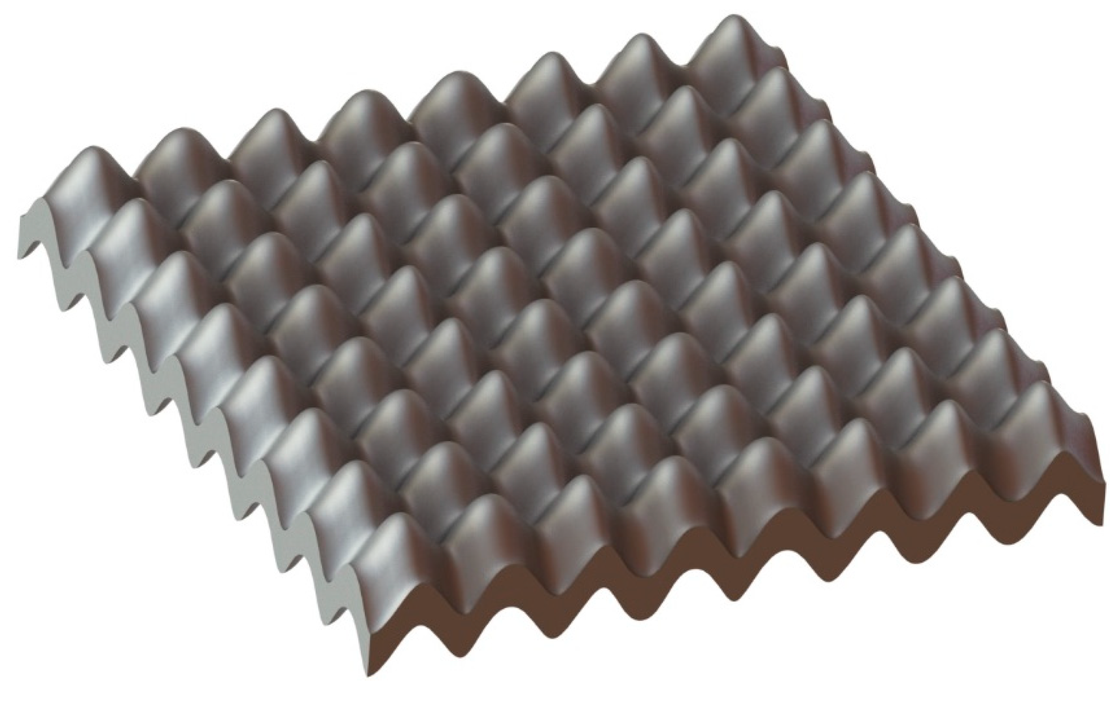
z.
Figure 1 shows the volumetric volume of a double corrugated plate AR1.6P02 with plate thickness
z = 0.1 mm.
where
P is the corrugation period,
AR is the aspect ratio of the
x and
y axes, and
z is plate thickness.
R is the radius of the equivalent straight tube [
43,
46]. However, here
R serves as a coefficient of the corrugation amplitude. The construction steps for building a double corrugated plate using CAD software are provided in the
Supplementary Materials.
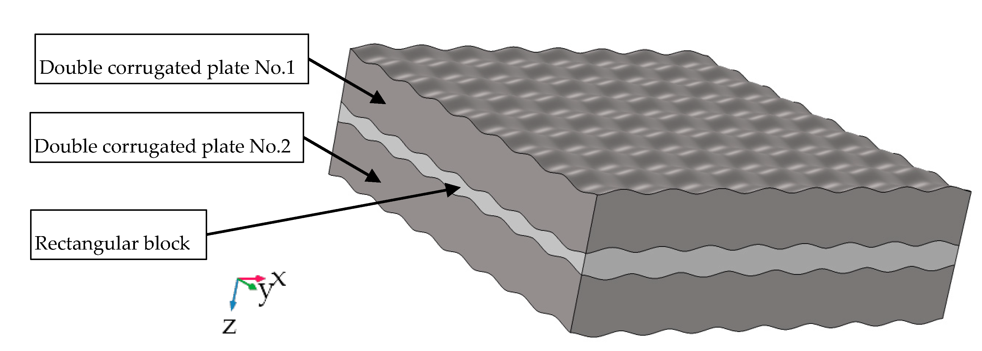
The numerical analysis was performed on the fluid flow in the passage between two plates, which was obtained by subtracting the surface of the geometry of interest from a rectangular block, as shown in
Figure 2. Note that the double corrugated plate No. 2 in
Figure 2 is offset by a half of the corrugation period, so the peaks of the plates would touch. However, in this study a small distance (which is maximum 20 μm) between the two double corrugated plates was left in order to obtain the numerically stable and physically correct solution.
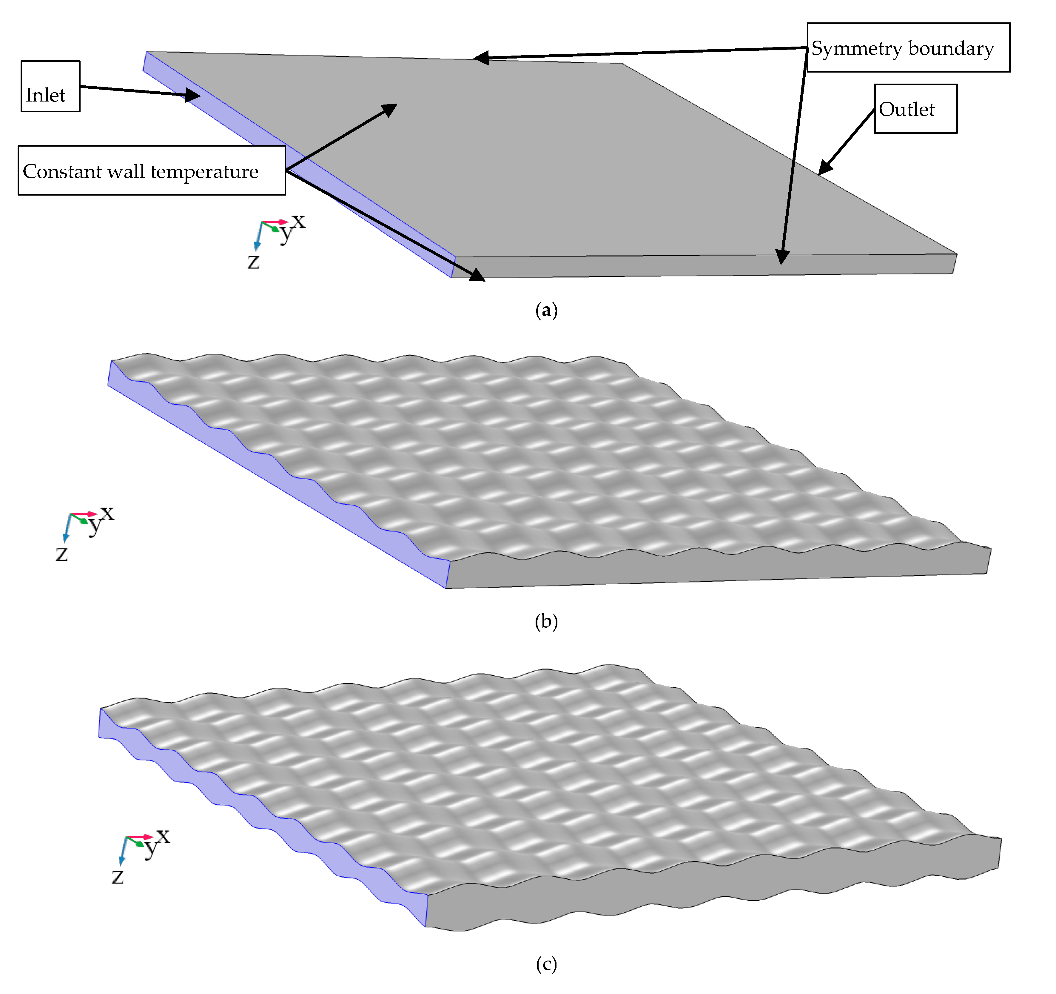
As shown in
Figure 3, a small differential volume of the fluid flowing in the passage between the parallel plates was modelled in order to reduce the required computational power. Laminar fully hydrodynamically developed non-isothermal fluid flows, assuming constant wall temperature conditions imitating the top and bottom plates as shown in
Figure 3a, were used. The name of the geometries constructed using double corrugated plates reflect their geometrical characteristics, e.g., AR1.1 means that the aspect ratio
AR = 1.1, P02 means that the corrugation period
P = 0.2 mm and the presence of the letter “M” means that the geometry consists of two double corrugated plates with the same geometrical characteristics. Note that all models were constructed in the same manner, and the explanation is given only for
Figure 3a in order to maintain the readability of the figure.
The laminar fluid flow regime is generally considered for magneto- and elastocaloric cooling, since the fluid flow channels are well below 1 mm and the laminar fluid flow condition is always satisfied [
47]. In order to assure the fully hydrodynamically developed flow, the periodic pressure-driven flow conditions were implemented on the inlet and outlet. Note that only fully hydrodynamically developed and thermally developing flow conditions were implemented into the analysed models. Symmetry boundary conditions were applied to the walls perpendicular to the inlet/outlet and the top/bottom surfaces, as shown in
Figure 3a. An incompressible fluid with constant properties was used for the simulations. The viscous dissipation was neglected since the analysis deals with laminar flow regime where the viscous dissipation is insignificant [
48]. Moreover, the Brinkman number,
Br, which is defined by Equation (2) [
48], was calculated. It was found that the maximum
, which proves that viscous dissipation can be neglected [
48]. The fluid properties and modelling conditions are listed in
Table 1.
where
μ is dynamic viscosity,
um is mean fluid velocity,
k is thermal conductivity,
Tw is wall temperature and Δ
Tlm is log-mean temperature difference, calculated as given by Equation (11).
It was reported in Refs. [
37,
43] that a periodic pressure condition can be used for modelling the convective heat transfer in the fluid flow in double corrugated geometries as long as the analysed geometry has a natural number of periods. In this study, the dimensions of the modelled geometries were selected so that all of them would have the same length,
l, and width,
w, allowing for a natural number of periods in the
x and
y directions. The height of the flow channels was adjusted for all of the analysed geometries so that the hydraulic diameter,
Dh, at the inlet would be held the same. Equation (3) defines the hydraulic diameter.
where
Ac is the cross-sectional area of the inlet, and
P is the perimeter of the inlet.
The geometrical data of all the analysed geometries is provided in
Table 2. One can see that the heat transfer surface area,
As, strongly depends on the corrugation intensity. For example, the
As of geometry AR1.6P02 is 40% larger compared to the flat geometry, however the
As of AR1.6P04 decreases by 24% compared to AR1.6P02. This change in
As is attributed to the difference in period.
The modelled geometries were meshed using a distributed swept mesh with triangular prisms. This allows one to create an evenly distributed mesh that captures all the geometrical features of the analysed geometries. Three boundary layers were added to the mesh. The mesh dependency study was carried out for each analysed geometry. The mesh evaluation criterion was the error,
err, in the change in Nusselt number,
Nu, as defined in Equation (4). The mesh was accepted if the change in
Nu at the selected mesh was not larger than 1% compared to the
Nu obtained using 25% finer and 25% coarser meshes. A larger
err of 1.5% was accepted only for the AR16P02 geometry, since a further increase in mesh density would have resulted in an unreasonably high burden on computing power. The selected mesh for each geometry resulted in a mesh density of over 2000000 elements per 1 mm
−3. All models were solved using the PARDISO solver with a relative error of 10
−6. The mass and energy balance for each model were solved to an accuracy of at least 10
−4 and 10
−3, respectively.
where subscripts t stands for the target mesh and 0.25 stands for 25% coarser/finer mesh.
The continuity equation for a laminar pressure driven flow is given in Equation (5).
where
u is the flow velocity vector. The momentum conservation equation is given by Equation (6).
Here,
p is the pressure field. The heat transport equation, neglecting pressure work and viscous dissipation, is given by Equation (7).
where
cp is a specific heat capacity.
No-slip boundary conditions were applied on the solid walls. A solid wall is treated as a streamline with zero velocity by imposing no-slip boundary conditions, as can be seen from Equation (8).
U here is the solid velocity, which is effectively equal to zero meaning that a very thin layer of fluid is not moving. This condition is used because the fluid molecules at the fluid-solid boundary do not move due to much higher attraction (adhesion) between solid and fluid compared to fluid and fluid particles.
where
n is the unit normal to the surface of the solid body.
3. Results
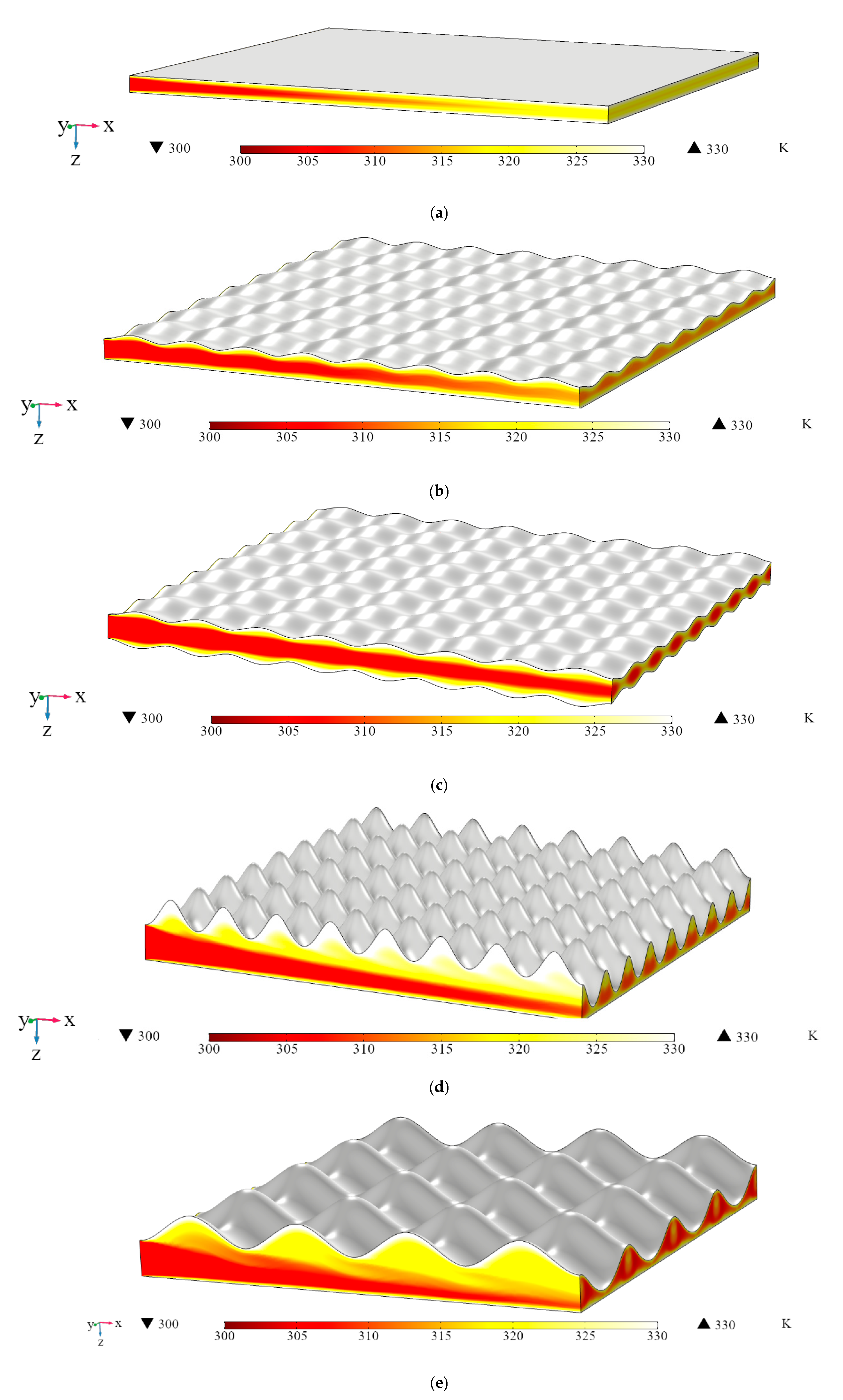
Figure 4 demonstrates how the double corrugated geometry disturbs the development of thermal boundary layers and enhances the heat transfer over the whole modelled domain compared to the flat plate geometry. Note that the three-dimensional temperature field presented in
Figure 4 is evaluated at the same pressure drop for all the geometries, which is Δ
p = 3397 Pa, and is the maximum available for the flat geometry where the development of the thermal boundary layers takes place rather fast. The geometrical features and slightly different cross-sectional area,
Ac, which is provided in
Table 2, lead to a different mass flow rate,
, at the inlet of each analysed geometry. One can also see that with the increasing corrugation intensity fluid flow is disturbed more effectively. However, as it is seen from
Figure 4d,e, a fast-flowing fluid tends to bypass the very intense corrugation, i.e., corrugation with high amplitude and small period, along the flow direction, resulting in an effectively narrowed size of the flow channel. This observation was also reported in [
43]. More clearly, the effect of the geometrical features on the fluid flow velocity is presented in
Figure 5.
From
Figure 5, it is clearly seen that the double corrugated geometry is causing strong fluctuations in the fluid flow velocity, and effectively in the mass flow rate across the geometry. It is also clear that the strongest fluctuations in fluid flow velocity are observed for AR1.6P04. This observation agrees with the findings from
Figure 4d,e.
The obtained data were analysed in terms of Nusselt number, pumping power,
W, and enhancement factor, also called the performance evaluation criterion (
PEC) at the constant pressure drop.
PEC is a widely accepted evaluation criteria that allows the direct comparison of the overall performance of enhanced heat transfer surfaces [
49]. The
PEC method can also be applied to evaluate the performance of the enhanced geometry compared to the reference geometry in terms of constant pumping power, or constant heating load or constant surface area. Generally,
PEC provides a good estimate of the effectiveness of the analysed heat exchangers [
46]. However, it is less suitable as a selection criterion of a magnetocaloric regenerator geometry [
45].
The data input into the model were the pressure difference between the inlet and outlet, Δ
p, the bulk fluid temperature at the inlet,
Ti, and the plate surface temperature,
Ts. The model output data were mass flow rate,
, average fluid flow velocity,
um, and fluid temperature at the outlet,
To. The Nusselt number was calculated using Equations (9)–(12) [
50]. The net rate of outflow thermal energy
q was calculated by Equation (9).
where
is mass flow rate,
T is temperature, and subscripts o and i denote inlet and outlet, respectively. The average convective heat transfer coefficient,
, was calculated using Equation (10).
where Δ
To,i is the temperature difference between the temperature of a plate surface,
Ts, and the bulk temperature of the fluid,
T, at the inlet and outlet. The average Nusselt number was calculated as given in Equation (12).
The pumping power,
W, is calculated as given in Equation (13).
The
PEC at constant pressure drop is calculated as given in Equation (14) [
49].
where
f is the friction factor and subscript p denotes the reference (flat) geometry. One can see that
PEC, evaluated at a constant pressure drop, is the ratio between the ratio of the Nusselt numbers of the enhanced geometry,
Nue, and of the flat (reference) geometry,
Nup, and the cubic root of the ratio between the friction factor of the enhanced geometry,
fe, and the flat geometry,
fp. All the
Nu and
f must be evaluated at the same Reynolds number,
Re. The friction factor is calculated using the simulation results for mean flow velocity,
um, and the specified pressure drop, Δ
p, as given in Equation (15) [
51].
In order to provide a clearer analysis of the obtained results, the thermo-hydraulic performances of the analysed geometries are presented as a function of Reynolds number,
Re. The Reynolds number was calculated using Equation (16).
The Graetz number, given by Equation (17), was calculated in order to analyse the thermal development of the modelled fluid flow.
The minimum
Gz of 6.4 was calculated for the modelled case with the lowest
Re of 17 obtained for the fluid flow in the passage between two flat plates, and the largest
Gz of 148 for the
Re of 357 obtained for the fluid flow in the passage shown in
Figure 4e. It can be stated that the fluid flow could thermally fully develop within the modelling domain in cases when the
Gz is low. However, it is also clear that a double corrugated geometry hinders the thermal development of the fluid flow, since it induces the fluid velocity at the same pressure drop conditions. This effectively results in larger
Re and larger
Gz.
4. Discussion
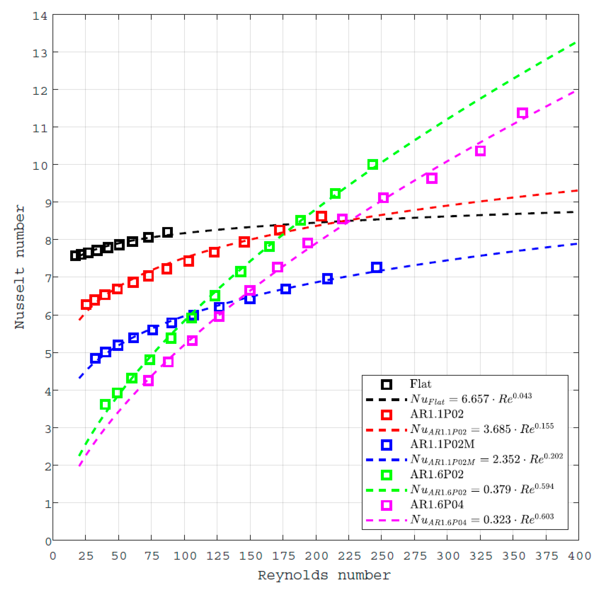
Figure 6 demonstrates the performance of the analysed geometries in terms of Nusselt number. The Nusselt number fit presented in
Figure 6 was obtained using the least square curve fit tool in MATLAB
®. It must be emphasised that the models of the flat plate geometry did not reach the required convergence accuracy under the fluid flow conditions with the three highest Δ
p, therefore the data obtained with these models were omitted from the further analysis.
One can see that at Re < 125, the Nu for the flat plate geometry is up to four times higher than for the AR1.6P04 geometry, which is the double corrugated plate with aspect ratio AR = 1.6 and corrugation period P = 0.4 mm. However, once the Re increases above 175, the geometries with double corrugated plates stacked with a flat plate start outperforming the reference geometry. It is also noticeable that the Nusselt number increases more drastically for geometries with higher AR compared to geometries with flat plates or low AR.
It is also noticeable that the Reynolds number strongly depends on the modelled geometry, since it drastically affects the fluid flow velocity, as shown in
Figure 5.
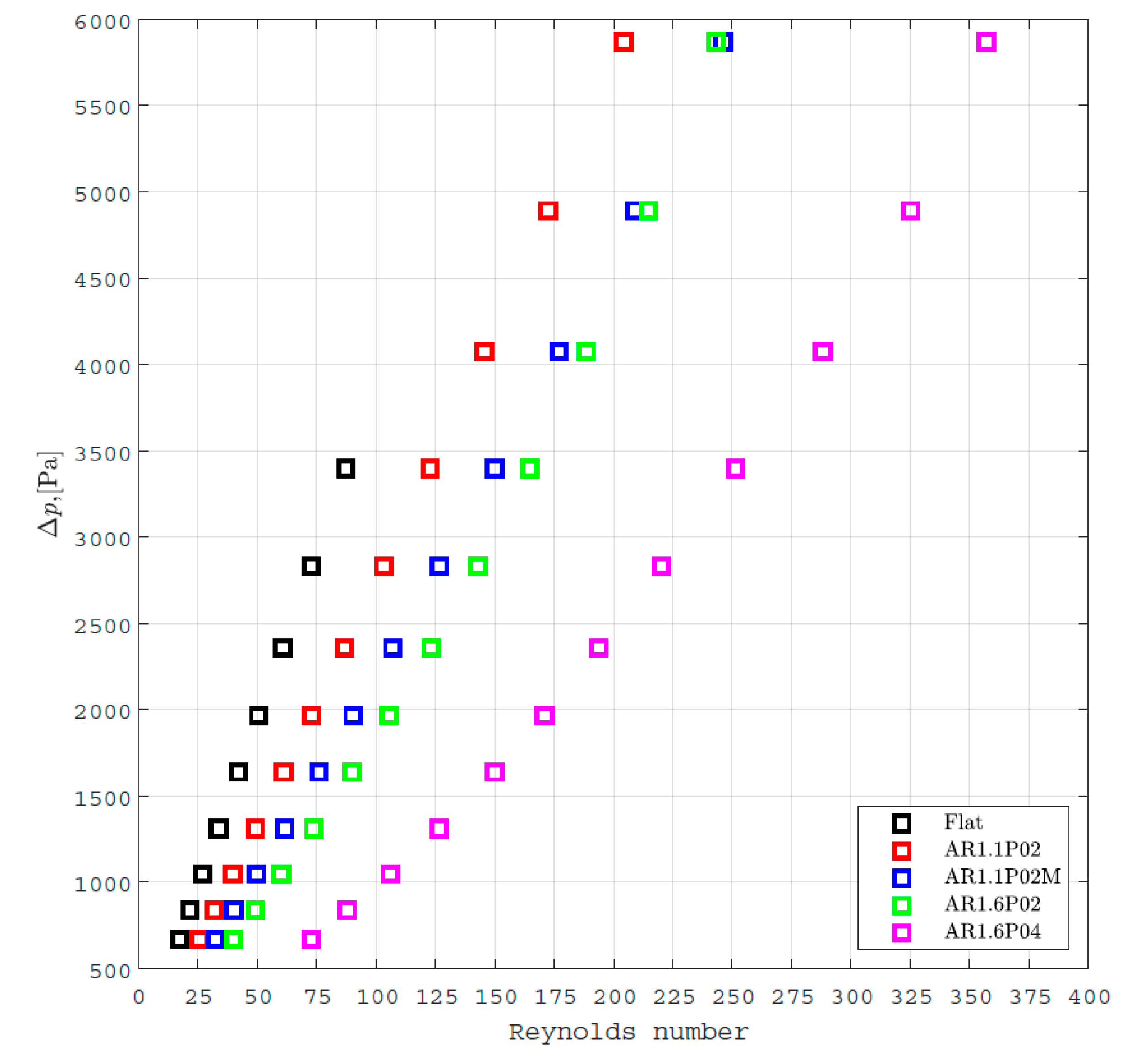
Figure 7 presents the relation between the pressure drop and the Reynolds number for all the modelled geometries.
For example, the
Re for the AR1.6P04 plate stacked together with a flat plate is up to three times higher than for the geometry consisting of two flat plates. From
Figure 7, it becomes clear that both the aspect ratio of the corrugation and the corrugation period have a very strong influence on flow velocity, and thus on the Reynolds number.
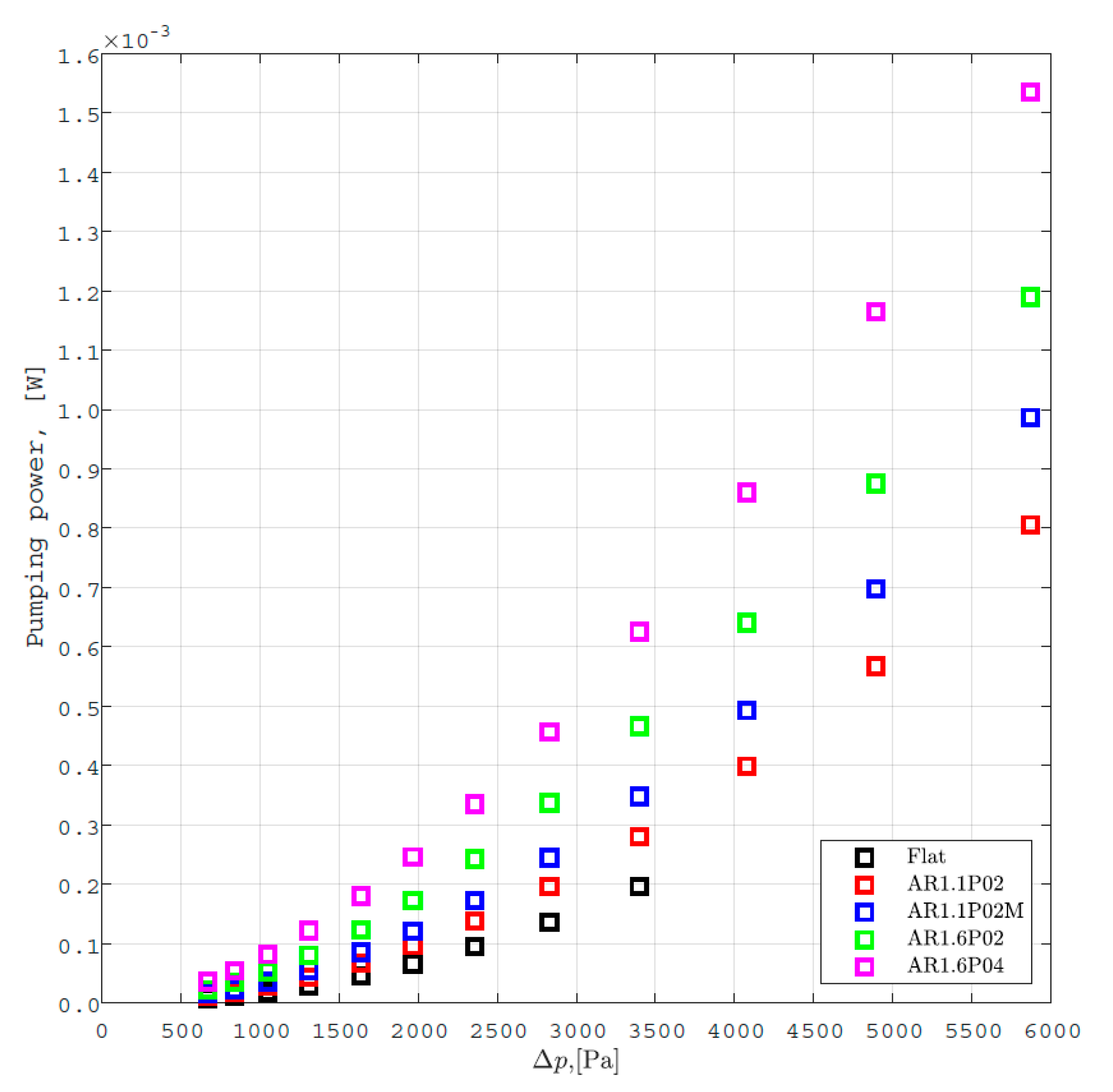
Figure 8 shows the pumping power,
W, as a function of Δ
p. One can see that the pumping power exponentially increases with the increase in pressure drop.
As expected, the higher the aspect ratio of the corrugation is, the higher is the pumping power required at the same pressure drop conditions. However, it is interesting to observe that the double corrugated plates with
AR = 1.6 with
P = 0.2 mm demonstrate from 20% to 40% lower required pumping power than the same geometry with
P = 0.4 mm even though the cross-section area at the inlet for both geometries is effectively the same.
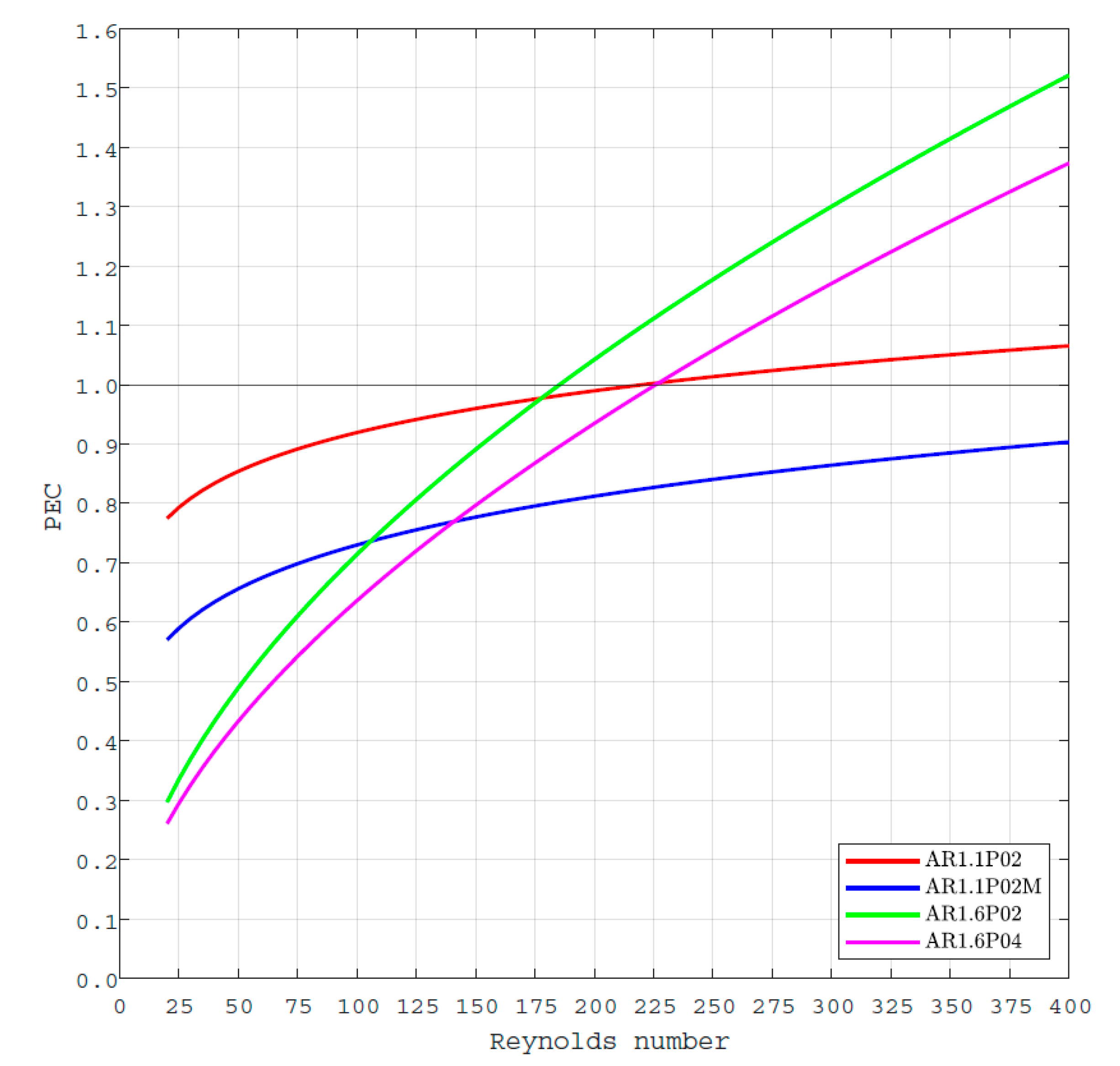
Figure 9 shows the
PEC as the function of Reynolds number.
Note that to obtain the
PEC values, the data fits for the Nusselt number as well as for the friction factor were used. The data fit for the friction factor was obtained using the least square curve fit tool in MATLAB
®. The friction factor data were fit to the most commonly used expression given by Equation (18).
where
a is the permeability factor, and
b is a coefficient.
As can be seen from Equation (14),
PEC is a tool to compare the overall thermo-hydraulic performance of an enhanced geometry with respect to the reference geometry [
49]. From
Figure 9, one can see that at the region of
Re < 175, the
PEC of the double corrugated geometries is lower than 1. This means that their overall performance is lower than of the flat plate geometry. However, one should remember that the passage between the stacked double corrugated plates is increased, reducing its potential compactness in a full-scale regenerator, which consists of multiple plates. Thus, it is practically possible that the double corrugated geometries would outperform the reference geometry even at a low
Re range.
One can see from
Figure 9 that the
PEC dramatically increases with the increasing Reynolds number for the double corrugated plate geometry with
AR = 1.6. In fact, once the Reynolds number exceeds 175, the double corrugated plate geometries, except AR1.1P02M, outperform the flat plate regenerator. It must be emphasised that even at
PEC values around 1, the double corrugated plate geometries have an advantage over the flat plate geometry by improving the compactness of the elastocaloric regenerator.
Another important factor when considering double corrugated plates as a choice for the regenerator geometry is manufacturing precision. While the fabrication of such geometries is possible using electrical discharge machining (EDM), or electrochemical machining (ECM), it would be very challenging, if at all possible, to assure a constant cross-sectional area at any arbitrary point of the geometry. This may lead to an inhomogeneous strain distribution inside the geometry, and thus an inhomogeneous eCE. However, experimental investigation in order to draw clear conclusions is needed.
Finally, the double corrugated plate geometry can be applied not only as a regenerator geometry for elastocaloric cooling applications. It can be seen from the presented results that the double corrugated plate geometry has the potential to enhance the heat transfer at a sufficient pressure drop compared to the flat plate geometry. This means that the double corrugated plate geometry can be exploited in plate heat exchangers for a wide range of applications.
5. Conclusions
This paper presents the CFD simulation results of passive double corrugated plate regenerators intended to be used for elastocaloric applications. From the first results, it is clear that the double corrugated plate geometry has the potential to improve the overall thermohydraulic performance of an elastocaloric regenerator, or a plate heat exchanger provided, that the double corrugated geometry is properly optimised.
In this study, it was found that the double corrugated plates with AR = 1.6 provide the highest overall performance in terms of PEC at a Re > 175, compared with other types of double corrugated plates. This emphasises the potential of the double corrugated plate geometry to increase the thermohydraulic performance of the elastocaloric regenerators and their compactness.
Finally, elastocaloric regenerators constructed from a combination of double corrugated plates can be exploited in a compression cycle, which leads to the increased fatigue life of an elastocaloric regenerator. In future studies, a more detailed numerical analysis of the performance of double corrugation as the geometry of an elastocaloric regenerator, including studies on structural mechanics, is going to be carried out. The obtained simulation results will be experimentally validated in terms of thermohydraulic and elastocaloric performance. Moreover, the mechanical stability of the double corrugated plate regenerators under compression loading is going to be investigated. The results presented in this article serve as selection criteria for choosing the most promising geometries for further investigation, and provide insights into the importance of various geometrical parameters, such as corrugation period or aspect ratio.

 ,
, 


