Article

Safety Analysis of a Modified Cooperative Adaptive Cruise Control Algorithm Accounting for Communication Delay

School of Transportation, Southeast University, No.2 Southeast University Road, Nanjing 211189, China
*
Author to whom correspondence should be addressed.
Sustainability 2020, 12(18), 7568; https://doi.org/10.3390/su12187568
Submission received: 15 August 2020 / Revised: 11 September 2020 / Accepted: 11 September 2020 / Published: 14 September 2020
(This article belongs to the Special Issue Traffic Safety within a Sustainable Transportation System)

Abstract

:
Cooperative adaptive cruise control (CACC) is a promising technology to improve traffic efficiency and enhance road safety. In this paper, a modified CACC control model considering the communication time delay is proposed, which is used to investigate the longitudinal safety impacts of the communication time delay to the CACC platoon. Then, the communication time delay model is integrated into the CACC model to simulate the realistic information transfer process in the CACC platoon. Then a microscopic CACC platoon simulation is designed and conducted to verify the feasibility and reliability of the modified CACC control algorithm. The obtained results reveal that the modified CACC control algorithm can not only reduce about 96.6% of inter-vehicle spacing error, but also enhance the vehicles’ ability to sense the upstream traffic changes. Furthermore, to quantitatively analyze the longitudinal safety influence of the time delay caused by representative communication systems, sensitivity analysis experiments of headway time were designed and conducted. In the sensitivity analysis, the time exposed time-to-collision (TET) and the time-integrated time-to-collision (TIT) were introduced as the key performance indicators (KPIs) to quantify the rear-end collision risks. Sensitivity analysis results demonstrate that the performance of the CACC platoon is strictly related to the applied wireless communication style. Furthermore, the CACC system supported by the 5th generation (5G) communication system shows great advantages in narrowing the minimal headway time gap and reducing the rear-end collision risks.

1. Introduction

It is reported that millions of people lost their lives from roadway crashes on the freeway around the word, and the number of casualties is still increasing steadily in recent years [1]. The driver factors, such as mal-operation and fatigue driving, have been considered as the leading cause of most crashes [2]. To handle this issue, implementing intelligent transportation system (ITS) applications is recognized as a promising means to improve traffic safety [3]. The 5th generation (5G) mobile network services, an emerging technology, soon to be under large-scale promotion, is believed to have great potential to improve the ITS, especially on autonomous vehicle technologies. In general, it is well-known that 5G networks are characterized by three unique features: (1) ubiquitous connectivity, (2) extremely low latency, and (3) very high-speed data transfer rate (typically of Gbps order) [4,5]. Compared with the current.
Long therm evolution(LTE)networks, the 5G networks will significantly improve users’ perceived quality of service (QoS). The 5G wireless communication systems, with improved data rates, capacity, latency, and QoS, are expected to be the panacea to the most existing problem of information transfer in the intelligent transportation systems. The 5G networks are expected to serve the advancement and implementation of self-driving technologies.
Connected and automated vehicles (CAV) is one of the most recent developments of information technology; the emerging communication technologies can significantly improve the safety and efficiency of the transportation road network as well. The main factors that affect CAVs’ longitudinal safety include vehicle dynamics [6], the intervehicle spacing policy [7], information flow topology [8], and the quality of intervehicle sensing and communication [6,9]. In particular, communication delay, which inherently exists in vehicle-to-vehicle (V2V) and the vehicle-to-infrastructure (V2I) communications, can significantly compromise longitudinal safety [9], that is, since the CAV vehicle functionality relies to a large extent on vehicle information transmitted by wireless communication, e.g., the position, velocity, actual, and desired accelerations.
Generally, in communications, connected vehicle technologies can be classified into two categories: V2V communications and the V2I communications. To date, both the V2V and V2I were mostly based on the dedicated short-range communication (DSRC) system. With the 5G era arriving, the V2V and I2V communication systems also could be based on the public 5G mobile network. Under reliable connective communication circumstances, each connected self-driving vehicle can receive real-time dynamic driving status information from other connected vehicles, including position, speed, and acceleration, without the need to construct extra dedicated roadside communication infrastructure. Along with the automatic driving technologies updating, traffic safety and efficiency are expected to improve significantly in the transportation road network, especially on the freeways, there are many traffic accidents, such as rear-end collisions.
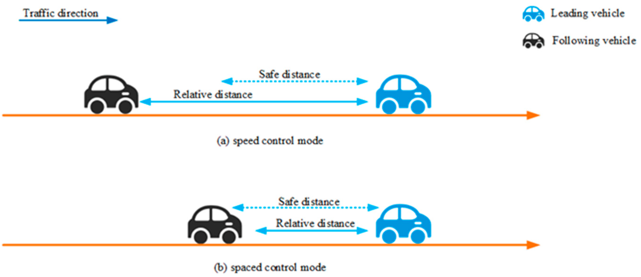
Adaptive cruise control (ACC), as one of the earliest automobile autonomous control systems, has been widely studied and was designed in the last few decades. As illustrated in Figure 1, ACC vehicles are without communication devices, instead mostly only equipped with sensors, such as radar or lidar, to sense the status of adjacent vehicles. The vehicle-mounted sensors can measure the distance to the preceding vehicle (lead car) and the relative velocity of each vehicle in the same lane. Generally, the ACC system can operate in two modes: one is the speed control mode, which is shown in Figure 1a, and the other is the spacing control mode, which is shown in Figure 1b. When the relative distance between the subject vehicle and the preceding car is bigger than the safe distance, the following vehicles travel at the driver-set speed. If the spatial gap between the subject vehicle and the preceding one becomes narrower than the safe distance, then the subject vehicle will transfer to the space control mode smoothly, which is dedicated to maintaining a safe distance from the preceding vehicle. The ACC controller is most widely known for its liner feedback control strategy, where acceleration is proportional to the deviation from target spacing and the relative speed with the preceding vehicle. According to different target spacing, the linear feedback control strategy can be further divided into two categorie: the, constant time headway (CTH) policy [10] and the constant spacing (CS) policy [11].
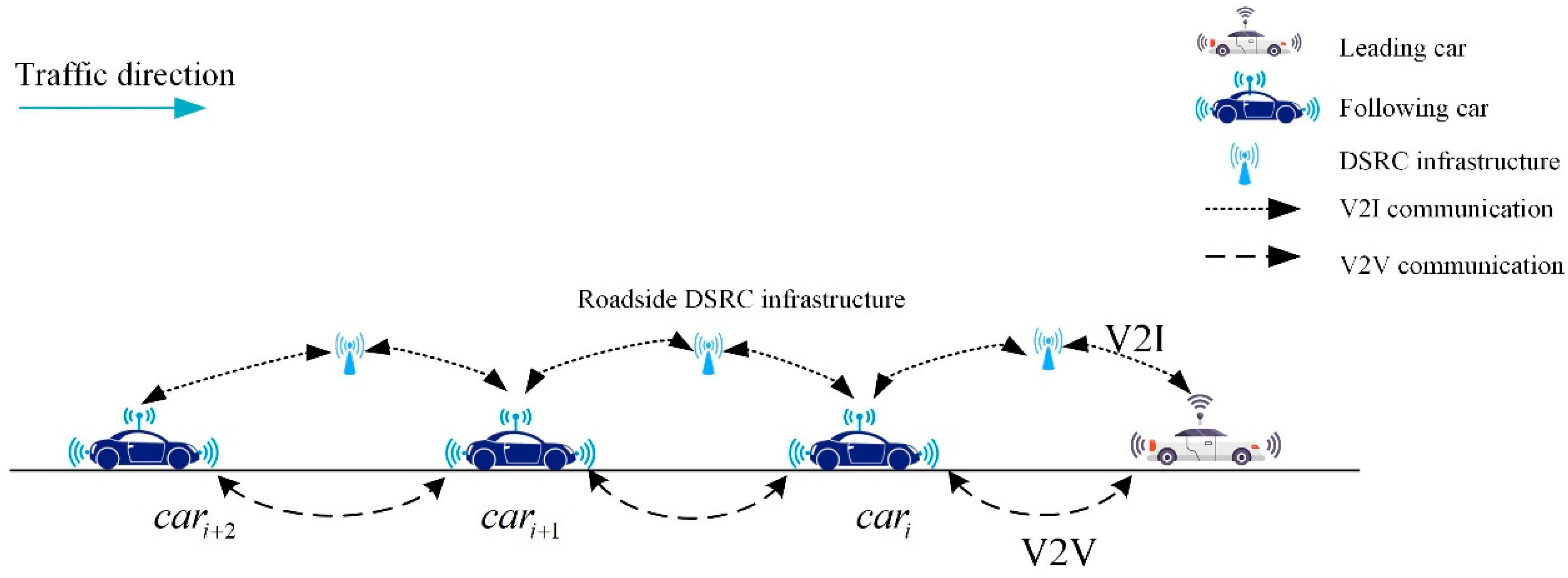
The rapid development of communication technologies, especially short-range communication technology, has been widely integrated into ACC systems. The evolved version of ACC incorporated short-range communication technologies, such as DSRC into the ACC systems to enable cooperative sensing and information exchange. By adding the vehicle-to-vehicle (V2V) or the vehicle-infrastructure (V2I) wireless communication components, the strengthened ACC systems can gain enhanced performance, leading to a cooperative ACC (CACC) system. Therefore, the CACC system is an extension of the ACC system, with timely information transferred between the controlled vehicles which can minimize the speed differences among the vehicles in a platoon and maintain stable and safe headways between adjacent vehicles on the freeway [12]. All in all, the CACC system is a more sophisticated variant of ACC, and it is going to be commercially available in the near future [5]. CACC is one of the typical intelligent vehicle longitudinal control strategies which is particularly promising due to its potential to drastically improve the traffic safety level and stability on the freeway. As illustrated in Figure 2, in the previous DSRC-CACC system, the vehicles under a CACC platoon typically were communicated by the dedicated short-range communication (DSRC) system, due to the current 4G LTE networks not being reliable enough to meet the moving vehicles’ control requirement. Recently, authors in reference [13] proposed a hybrid IEEE 802.11p–LTE HetNet architecture, which integrated the DSRC and the LTE networks. However, the communication component of the conventional CACC systems typically relied on the dedicated roadside communication infrastructure. Therefore, the CACC vehicles can mostly only function well under the roadside communication infrastructure in well-built circumstances [13]. Due to the rigid external circumstance limitation, the extensive implementation of the connected CACC vehicles remains sluggish.
The rest of the paper is organized as follows. Section 2 is a review of related works. Then, an overview of cruise control algorithms is introduced in Section 3. In this section, the typical ACC and CACC models proposed by the California Partners for Advanced Transit and Highways(PATH) are introduced. Then, a modified CACC algorithm accounting for time delay and is introduced in Section 4. Several simulation experiments to validate the proposed CACC models are included in Section 5; the sensitivity analysis is provided in this section as well. Finally, this paper ends with a brief conclusion and recommendation in Section 6.

2. A Review of Related Work

Though various wireless communication systems exist, V2V and V2I communication are mostly provided by DSRC, based on the Electrical and Electronics Engineers 802.11p (IEEE 802.11p) vehicular communications standards and the Long Term Evolution (4G LTE) by 3rd Generation Partnership Project (3GPP) for vehicular networking standards. In the last 5 years, Mir and Filali [14] compared the two most viable communication standards, IEEE 802.11p (DSRC) and LTE (4G), for vehicular networking. The results indicated that both IEEE 802.11p and LTE vehicular networking applications are time-critical, and the advantages of DSRC are easy deployment, low cost, and the capability to support V2V communications. Nonetheless, this technology suffers from scalability issues, unbounded delays, and the lack of deterministic quality of service (QoS) guarantees. On the other hand, literature [15] performed some experiments to evaluate the performance of IEEE 802.11p vehicular communications, while transmitting basic safety messages (BSM). A total of nine experiments were conducted for measuring the latency values while transmitting BSM packets over the IEEE 802.11p radio channel. Their results denoted that the average latency increases with an average distance between the communicating vehicles.
The authors of [16] studied the IEEE 802.11p-based cooperative driving systems in urban expressways. Their measurements and analyses indicated that setting roadside relay communication stations at the top of the road slopes can effectively reduce Non-Line-of-Sight (NLoS) cases and improve the communication reliability. To provide effective group communication between vehicular ad hoc networks (VANETs), Charitos and Kalivas (2017) [17] proposed the hybrid IEEE 802.11p-LTE network architecture. In the references [18,19], various scenarios for cellular network and vehicular communication were presented, and the authors analyzed the performance of the hybrid communication system, which combined the LTE and the IEEE 802.11p. The results showed that in terms of IEEE 802.11p, the values of communication latency were somewhat higher: approximately between (450–800 ms), compared to the LTE (180–300 ms). With the combination of IEEE 802.11p–LTE, the average delay can be significantly decreased to (110–150 ms).
In 2020, the first commercial release of the fifth-generation cellular system (5G) was launched according to the road map of the 3rd Generation Partnership Project (3GPP) and the International Telecommunication Union (ITU) road map for the International Mobile Telecommunications 2020 system (IMT-2020) [20,21]. In the 5G era, the extreme latency, high-speed data transfer, and ubiquitous connectivity will be the salient features of 5G networks, which are expected to bring significant positive effects to self-driving development, especially the CACC system [4,5,22]. In the literature of Sachs and Andersson et al. (2019), the 5G functionality for ultra-reliable and low-latency communication (URLLC) services is detailed described [23]. It also explained how 5G new radio (NR) and the evolved long-term evolution (LTE) radio interface can achieve guaranteed low-latency wireless transmission. For intelligent transportation systems (ITSs) with URLLC services, it can promote real-time maneuver coordination among autonomous vehicles, and coordination with the transportation infrastructure become reality. According to the requirement of ITU and 3GPP, 5G needs to be able to successfully transmit a 32-B message over the 5G radio interface within 1 ms. Furthermore, the 3GPP further requires that the average latency of 5G radio interface to be decreased to 0.5 ms, which is not required for the 5G evaluation at ITU [24].
In the majority of CACC systems, the vehicles in the platoon are required to communicate with the nearest preceding vehicle and the leading vehicle [3]. In order to standardize the vehicular communication system, which is a crucial functional block in the CACC systems, the Connected Vehicle Reference Implementation Architecture (CVRIA) is proposed by the US Department of Transportation. The CVRIA provides the communication framework between vehicles and roadside units, including V2V and V2I [25]. Under the 3G or 4G era, when the number of served vehicles increases inside the coverage area, the communication bandwidth would become insufficient; therefore, short-range wireless technologies are necessary supplements for vehicular communication. DSRC has been chosen as the standard short-range communication protocol for connected vehicle applications by the Federal Communications Commission (FCC) in the US [26]. Another form of vehicular network is VANETs, with various features, such as high node mobility and dynamic topology [27], which is one of the extensively explored methods for vehicular communication. In [27], the authors discussed the research challenges of routing in VANETs and then analyzed the future trends of VANETs.
According to the literature reviewed, in the previous research, various CACC models were explored and studied in simulation experiments and field tests. However, most of the CACC systems are based on the DSRC system, LTE communication system, or the hybrid network of DSRC and LTE systems. The recent progress in 5th generation wireless systems (5G) shows that the millimeter-wave 5G has an excellent capability of decreasing communication latency. To date, there have been few studies which investigated the potential influences of the next-generation communication technologies on the CACC system, especially the longitudinal safety impacts of CACC fleets. To fulfill this research gap, this paper is focused on quantitatively evaluating the rear-end collision risks of the CACC platoons, which rely on different communication systems. This study also aimed to reduce the rear-end collision risks on the freeway by modifying the typical CACC algorithm. The modified CACC algorithm, which is derived from the California Partners or Advanced Transit and Highways (PATH) [28,29], was introduced in this paper. Moreover, to quantitatively evaluate the rear-end collision risks in a CACC fleet, two surrogate safety measures were also applied in this research. To the best of our knowledge, research devoted to the influence of communication delay on the CACC system longitudinal safety has rarely been reported in the literature before.
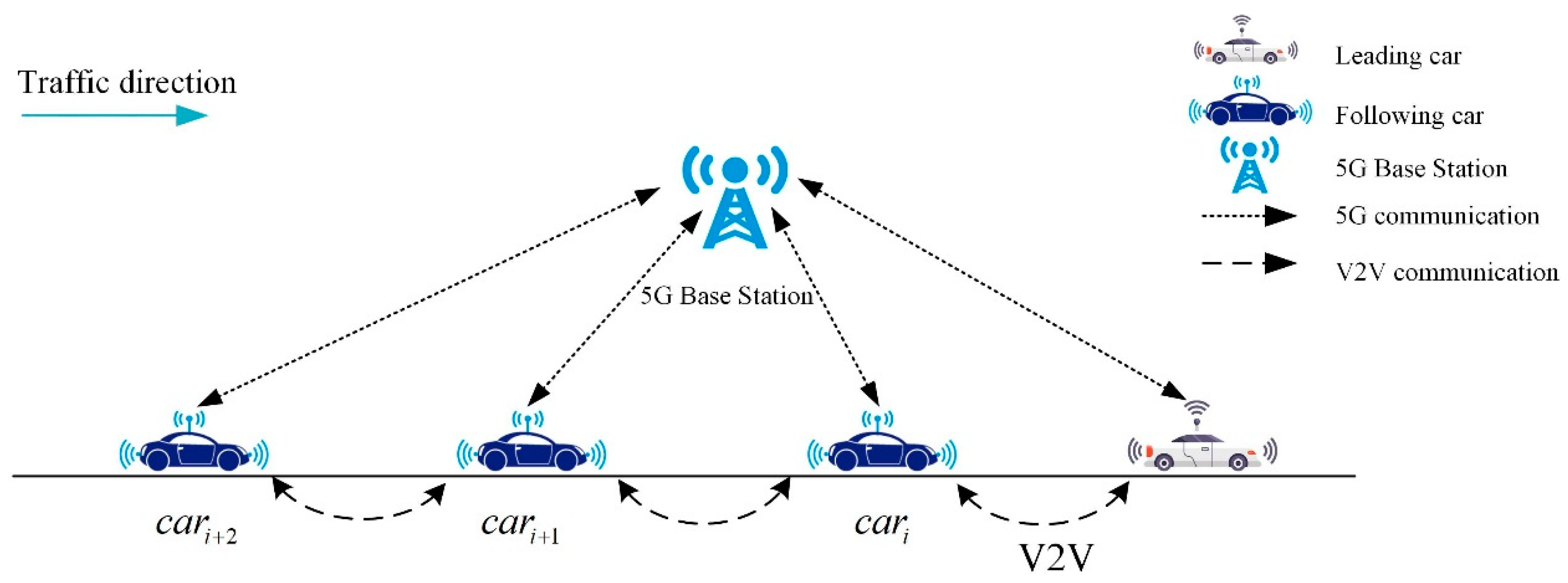
To overcome the communication delay existing in V2V and V2I communication, this paper proposed a novel network topology structure. Figure 3 illustrates the way that CACC vehicles under the 5G communication system are connected. Compared with the conventional cooperative adaptive cruise control system, vehicles equipped with the 5G communication devices can exchange real-time driving information not only via the dedicated short distance vehicular communication system, but also the widely existing 5G network signal. This provides a new way for the development of connected autonomous vehicles (CAVs), which can enhance their situational awareness and performance through the implementation of more robust system-level vehicle control strategies [30]. When the highly reliable 5G network circumstance is widely constructed, cooperative ACC platoon driving will become a particularly promising technology to improve road safety, fuel consumption, and traffic throughput without the need to expand the current roadside infrastructure [5].

3. Overview of Cruise Control Algorithms

3.1. Longitudinal Control Basic Principles

In the previous research, various longitudinal control algorithms and vehicle dynamic models have been proposed to establish the ACC and CACC system. The most commonly used longitudinal control algorithms are the theoretical car-following models, including the Gipps’ model, the intelligent driver model (IDM) [31], and the enhanced IDM [32]. However, the theoretical car following models sometimes make the following vehicles in the platoon produce unrealistic behaviors in some test scenarios, which suggests that the theoretical car following model cannot fully capture the microscopic dynamics of ACC and CACC vehicles [28]. The California Partners for Advanced Transit and Highways (PATH) proposed the realistic PATH ACC and CACC model, which is one of the few vehicle dynamics following models calibrated by realistic filed experimental data [28]. Generally, a CACC system consists of two components: one to manage the approaching maneuver to the leading vehicle and the other to regulate the car-following behaviors after a vehicle joins the CACC platoon [29]. The two sub-controllers work on the two different control stages, respectively.
When there is no vehicle in front of the subject car or this vehicle is far away from the preceding car, the approaching vehicle, shown in Figure 4, will work under the first control stage. In this process, the gap-closing sub-controller will be in charge of maintaining the smooth driving of the controlled vehicle, which is usually traveling on the preset desired velocity freely. On the other hand, as illustrated in Figure 4, when the following cars are close enough to the preceding ACC or CACC platoons, the gap-closing maneuver controller will switch to the second control stage, the gap regulation controller, smoothly. In this case, the vehicle will be controlled by the car-following sub-controller to keep a safe distance from the preceding vehicle.

3.2. The Classical ACC Algorithm

The ACC system, as one of the few eminent driving-assistant systems, is currently commercially available, primarily, on mid-class and premium vehicles. As is shown in the Figure 4, in this microscopic simulation testbed, the ACC model is introduced to simulate the driving behaviors of the fleet leading vehicles and the approaching car. In the commercially available ACC model, the acceleration of the subject vehicles is determined by the distance and speed errors, which can be mathematically expressed as follows:
d k = x k 1 x k t h w v k
s k = v k 1 v k
a k = λ 1 d k + λ 2 s k
In the Equation (1) the d k represents the distance errors between the subject and the preceding vehicles; the subscript k and k 1 indicate that the vehicles are the k-th and the k − 1-th vehicle in the platoon, respectively; x k and x k 1 denote the current longitudinal position of the subject vehicle and the preceding vehicle, respectively; v k represents the current speed of the subject vehicle; the t h w indicates the preset headway time gap between the preceding and the subject vehicles. In the Equation (2), where s k represents the speed errors of the k-th vehicle, which can be calculated by the velocity of the preceding vehicle v k 1 and the subject vehicles’ velocity v k . After the distance errors and speed errors are determined, the real-time acceleration a k of the subject vehicle can be updated by Equation (3), where λ 1 and λ 2 represent the proportional coefficients of the distance errors and velocity errors, respectively. According to the experimental test [28], the values of λ 1 = 0.23 s 2 and λ 2 = 0.07 s 2 were used in the calibrated ACC model. Note that, in the ACC system, all the real-time input variables, including v k , v k 1 and x k , x k 1 , are obtained through the measurement of vehicle-mounted sensors.

3.3. The PATH CACC Algorithm

To investigate the impacts of communication latency on the longitudinal safety of the CACC fleets, the simulation testbed in this research was constructed based on platoons, and the number of vehicles included in the platoon ranged from 4 to 8. Different from the ACC system, vehicles in the CACC platoons can transfer basic safety messages, such as real-time velocities, positions, accelerations, and decelerations, via the vehicle-mounted assistant communication equipment system. Based on these basic driving safety messages, the PATH CACC model was proposed by Milanés and Shladoveris [28], who calibrated this CACC model with realistic experimental data. The calibrated PATH CACC model is expressed as follows:
e k = x k 1 x k d min t h w v k
v k = v k p r e v + k p e k + k d e ˙ k
where e k presents the space gap errors of the k-th consecutive vehicle; x k 1 and denotes the longitudinal location of the preceding vehicle; x k and v k represent the current position and longitudinal velocity of the subject vehicle respectively; t h w denotes the time headway constant; d min represents the standstill distance. In subsequent experiments, the value of d min is set as 2.5 m, and t h w is set as 0.9 s. In the Equation (5), v k p r e v denotes the speed of the subject vehicle in the previous iteration; e ˙ k is the derivative of space gap errors; k p and k d denote the corrective coefficients of this model. These two parameters are identified as k p = 0.45 and k d = 0.25, which are calibrated by the realistic experimental data [28].

4. The Modified CACC Algorithm and Surrogate Safety Measures

4.1. The Modified CACC Algorithm

Note that, in the typical PATH CACC model, the intermediate variable e ˙ k was not defined specifically enough and the output control parameter a k is somewhat vague. According to Equation (4), theoretically, if we derivate both sides of Equation (4), then e ˙ k can be expressed as follows:
e ˙ k = v k 1 v k t h w a k    
where a k is the acceleration of the subject vehicle, which is one of the output variables of the CACC system [33,34]. Derived from the typical PATH CACC model, a more specifically defined and modified CACC model, is proposed in this paper, which is a linear state feedback control system as well. The feedback CACC model is expressed as follows:
a k = λ a a k 1 + λ g e g k + λ v s k
where λ a , λ g and λ v denote the static control gains; a k represents the current output acceleration of the subject vehicle and a k 1 denotes the acceleration of the preceding vehicle, which is one of the information units transferred from the preceding vehicle by the auxiliary communication system; e g k and s k , represent the space errors and the velocity errors, respectively. These two crucial input variables are specifically defined as follows:
e g k = g k G min t h w v k
s k = v k 1 v k
In the Equations (8) and (9), g k , G min , v k , v k 1 , and t h w denote, the current distance to the preceding vehicle, the defined minimal standstill safety distance, the longitudinal velocity of ego vehicle, the preceding vehicles’ speed, and the headway time constant, respectively.
In the previous study, the communication time delay is usually ignored. However, as previously stated, a communication delay inherently exists in reality, which plays a significant role in view of longitudinal safety. Accounting for communication time delay, the modified CACC model can be expressed as
a k = λ a a k 1 r + λ g ( g k G min t h w v k )                                                 + λ v ( v k + v k 1 r )
It can be noted that the introduced modifications are replacements of a k 1 and v k 1 with a k 1 r and v k 1 r , respectively. The a k 1 r and v k 1 r represent the following car received acceleration and velocity of the preceding vehicle. Although the introduced modification changes the CACC formula only slightly, its impact on the platoon performance is meaningful. This is caused by the fact that the modified formula accounts for the impacts of communication time delay. With the support of the 5G network, the 5G-mCACC describes a system that integrated the modified CACC controller with the 5G communication network.
In the above CACC model, generally, three basic safety message items are exchanged between the CACC vehicles. The details of the basic safety information exchange are shown in Table 1.
In this paper, the microscopic simulation testbed is constructed based on the modified CACC model. According to the previous research [34], the parameters of the CACC model can be determined as Table 2.
When the acceleration of a subject vehicle is determined in the simulation experiment, the current velocity v k and the longitudinal location x k , at time t, can be updated using the following equations:
v k = v k p r e + a k Δ t
x k = x k p r e + v k Δ t + 1 2 a k Δ t 2
where Δ t is the selected time-gap of every iteration; v k p r e and x k p r e represent the velocity and position of the subject vehicle in the previous iteration, respectively. In the simulation experiment, the iteration time gap Δ t was selected as 0.01 s (10 ms).

4.2. The Communication Time Delay Model

When the subject vehicle is receiving the basic safety information from a target vehicle, as the input signals of the CACC controller, the time delay should not be ignored in the information transferring process. Actually, in real electrical communication conditions, communication latency is always inevitable. To investigate the safety impacts of the communication latency to the CACC system, a time delay function is necessary to model the communication time delay during the process of information exchange between vehicles in the CACC platoons. Accounting for the communication time delay, the state transfer function can be mathematically expressed as the following equation [34]:
( s r e a l ( t ) s o b s ( t ) ) = ( f ( t ) f ( t - τ ) )
G ( s ) = F r e a l ( s ) F o b s ( s )
where s o b s ( t ) represents the signal received observation state at time t ; s r e a l ( t ) is the real state of the target vehicle at time t ; the τ denotes the communication and actuator time delay; and the G ( s ) denotes the state transfer function during the BSM exchange process. Where s ∈ C is the Laplace variable. F o b s ( s ) and F r e a l ( s ) denote the Laplace transform of the corresponding time-domain function s o b s ( t ) and s r e a l ( t ) , respectively.
According to the definition of Laplace transform, F real ( s ) = [ s r e a l ( t ) ] = [ f ( t ) ] , from the zero initial condition f ( t ) = 0, t 0 , for any input f ( t ) [ 0 , ) . Similarly, F o b s ( s ) = [ s o b s ( t ) ] . Then, the key is to prove the relationship between F o b s ( s ) and F r e a l ( s ) . Based on the definition of the Laplace transform, the inter-relationship can be deduced as follows:
F o b s ( s ) = [ s o b s ( t ) ] = [ f ( t τ ) ]                                                             = 0 + f ( t τ ) e s t d t                                                             = 0 τ f ( t τ ) e s t d t + τ + f ( t τ ) e s t d t
When t 0 , f ( t ) = 0, which proved that 0 τ f ( t τ ) e s t d t = 0 . Then the upper equation can be simplified as F o b s ( s ) = τ + f ( t τ ) e s t d t . Now, use u as a variable substitution of ( t τ ). Then
F o b s ( s ) = 0 + f ( μ ) e s ( μ + τ ) d μ                                                           = e s τ 0 + f ( μ ) e s μ d μ                                                           = e s τ F real ( s )
According to the above proof, the inter-relationship between F o b s ( s ) and F r e a l ( s ) can be simply expressed as F o b s ( s )     = e s τ F real ( s ) , integrating this model with the most widely used longitude dynamics model [35] F real ( s ) = 1 1 + s , then F o b s ( s )     = e s τ 1 + s ; the longitudinal dynamics model is be used in the subsequent simulation experiments.

4.3. Surrogate Safety Measures

To quantify and analyze the longitudinal safety impacts of the communication latency to the various CACC systems, an appropriate surrogate safety measure is needed in this research. In the previous research, a number of indicators have been proposed to evaluate traffic collision risks, such as the time exposed rear-end crash risks index (TERCRI) [36], time to collision (TCC) [37], time exposed time-to collision (TET) [38], the time-integrated time-to-collision (TIT) [39], etc.
Among these measurements, TCC, firstly proposed by Hayward, (1972), is one of the most commonly utilized indicators to evaluate rear-end crash risks [40,41,42,43,44,45,46]. According to the definition of TCC [37], it refers to the time that remains for the occurrence of a collision between the two successive vehicles in the same lane. To be more specific, if the longitudinal velocity of the following vehicle is larger than the preceding one, and they maintain their speed without any change, then a rear-end accident will occur sometime later. The TCC exactly represents this time, which can be calculated using the following equation:
T T C i ( t ) = { x i 1 ( t ) x i ( t ) L i 1 v i ( t ) v i 1 ( t ) i f   v i ( t ) > v i 1 ( t ) i f   v i ( t ) v i 1 ( t )
where T T C i ( t ) is the TTC value of the vehicle i at the time t ; x i ( t ) and v i ( t ) represent the position and velocity of the vehicle i at the time t ; L i 1 denotes the length of the preceding vehicle. Actually, a smaller TTC value indicates that the rear-end crash risk is higher.
There are numerous TTC values at every simulation time step, due to the fact that there are always many vehicles in the CACC platoons. Accordingly, the TET and TIT aggregated indicators for crash risk assessments were proposed in the previous study. These two crash risk measurement indicators were derived from TTC, and they are selected as the surrogate safety measures used in this research. According to the definitions of TET and TIT, the TET refers to the total time that the operating vehicles under dangerous traffic situations and the TIT refers to the entity of the TTC value lower than the safety threshold TTC*. The values of TET and TIT can be calculated using the following equations:
T E T ( t ) = i = 1 N δ t · Δ t , δ t = { 1 , 0 < T T C i ( t ) T T C * 0 , o t h e r w i s e
T E T = t = 0 T T E T ( t )
T I T ( t ) = i = 1 N [ 1 T T C i ( t ) 1 T T C * ] · Δ t ,   0 < T T C i ( t ) T T C *
T I T = t = 0 T T I T ( t )
where t is the time instant; i represents ID tag of the vehicles; N represents the number of vehicles in the experimental vehicle platoon; δ t is the switching variable at the time t ; Δ t denotes the iteration time gap, the value of Δ t is set as 0.01 s(10 ms) in this paper, which is more accurate than the general selected value 0.1 s(100 ms); and T represents the simulation time period setting; T T C * is the TCC threshold, which is used to distinguish the dangerous traffic situations from the experiments. According to the previous research, the rational value of the TCC threshold could range from 1 to 3 s [43,44].

5. Simulation Experiments and Results Discussion

To date, as the application of the 5G-mCACC system in practice is rare, it is impractical to quantify the safety performance of the 5G-mCACC system in large scale real-world filed tests. Therefore, simulation experiments are needed to evaluate the proposed modified 5G-CACC system. In this paper, the microscopic simulation testbed was designed and implemented, which was constructed with MATLAB R2018b software. The modified longitudinal control algorithms and surrogate safety measures were used in this section, which are implemented in the simulation testbed to quantify and analyze the impacts of the communication latency to the CACC systems.

5.1. Designed Experiment and Tested Scenarios

The overarching goal of this study is to investigate the longitudinal safety performance of the proposed novel 5G-mCACC system and demonstrate its technical feasibility. To compare the difference between the newly proposed 5G-mCACC system and the previous CACC system, which relied on the traditional communication infrastructures, such as the DSRC communication system, 4G LTE networks, and DSRC–LTE hybrid networks, the comparison experiments were designed and tested in this paper.
As mentioned earlier in this paper, the previous research results verified that the time delay of the DSRC system is approximately between 250–600 ms [13], and the time delay of the LTE is about 180–300 ms [14], while the average time delay of the hybrid DSRC–LTE network is significantly decreased to 110–150 ms [17,18]. In the subsequent sensitivity analysis comparative experiment, the communication time delay of the CACC system is set as 100 ms, 200 ms, and 300 ms, which represent the time delay caused by the hybrid network, the LTE communication system, and the DSRC system, respectively.
In realistic traffic scenarios, traffic oscillation is a very common phenomenon, which is a kind of traffic disturbance propagation caused by when the leading vehicle stops or accelerates suddenly. If the distance between the preceding vehicle and the following vehicle is insufficient, and the following vehicle does not decelerate in time, a rear-end collision accident may occur. This kind of longitudinal microscopic behavior of the automatically controlled vehicles is simulated in the constructed MATLAB simulation platform.

5.2. Performance of the PATH-ACC System

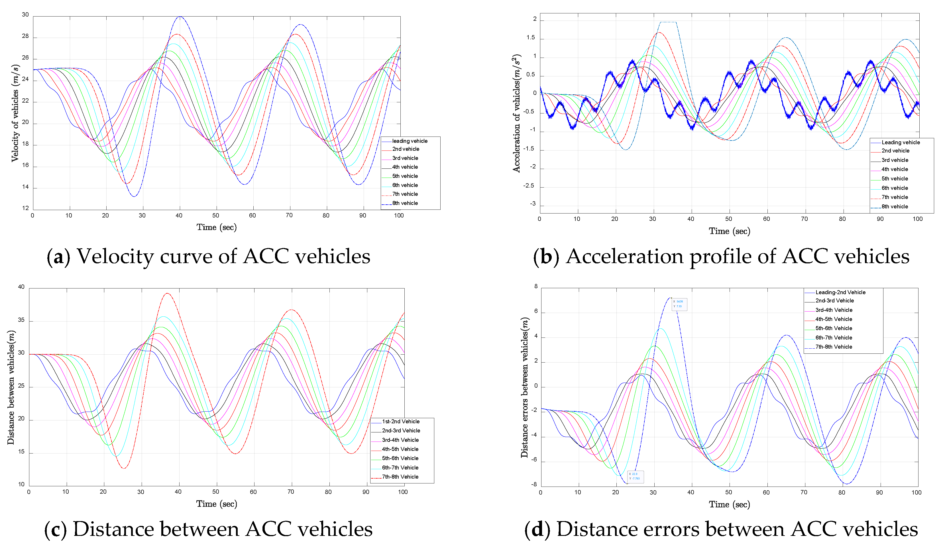
Firstly, the microscopic behaviors of the PATH-ACC system are simulated in the experiment, which is used as a comparison test of the subsequent CACC experiment. As illustrated in Figure 5, an ACC platoon constructed with eight ACC vehicles is simulated in this section, and the simulation period is set as 100 s.
As is shown above, Figure 5 illustrates the velocity, acceleration, spacing gap, and distance error curve of the PATH-ACC vehicles under the designed simulation test scenario. Figure 5 indicates that all the vehicles in the platoon start with an initial velocity of 25 m/s. As shown in Figure 5b, considering driving comfort, the acceleration of the leading vehicle always ranges within −0.3 g (−2.943 m / s 2 ) and 0.2 g (1.962 m / s 2 ), which corresponds to the requirements of the ISO 15,622 intelligent transport systems standard [47]. Figure 5c is the real-time intervehicle spacing gap response graph of the ACC platoon. This picture also indicates that the initial position of each vehicle is set as 30 m apart, which is a little wider than the desired distance gap. Furthermore, to directly reflect the real-time safety situation of every ACC vehicle during the simulation, the distance error convergence curve graph is shown in Figure 5d. The spacing errors are the deviations between the real-time relative distance and the desired safety distance.
Observing Figure 5a, it is not difficult to find out that the velocity shockwave is gradually amplified in the ACC platoons. Similar amplified phenomena also can be found in Figure 5c,d, which indicates that if the disturbance affected the leading vehicle’s behavior cannot be attenuated in time, the distance gap and spacing error between the ACC platoons will be continuously amplified. If the number of vehicles in the ACC platoons continuously increases, then the speed shockwave and the spacing error will be magnified infinitely in the following vehicle. Consequently, this may seriously compromise the platoon vehicle’s longitudinal safety. Furthermore, the spacing error fluctuating range is also reflected in Figure 5d, which clearly illustrates that the spacing error of the ACC platoons ranges from −7.7 m to +7.2 m in the most of the simulation period. Finally, from the acceleration response curve Figure 5b, we can see that, in the ACC platoon, only the second vehicle can feel the acceleration oscillation of the leading vehicle, which means that information dissemination lags in the ACC platoon.

5.3. Performance of the Modified CACC System

In order to compare the safety performance of the modified CACC system with the typical ACC system, in the following comparative experiment, most of the experimental conditions remained unchanged. The only difference between these two experiments is the control algorithm, which is chosen as the unique controlled variable. In addition, the headway time constant of the CACC fleet is set as 0.9 s, and the communication time delay is 0.02 s, which is used to simulate the 5G communication latency. Under the designed tested scenario, the velocity, spacing gap, distance error, and real-time acceleration of the CACC vehicles are recorded as well. The specific performance of the modified 5G-CACC vehicles is shown in Figure 6.
Figure 6 displays the performances of vehicles controlled by the 5G-mCACC system. Figure 6a–d represent the velocity, acceleration, intervehicle distance, and space error convergence profile of the fleet in the designed test scenario. From Figure 6a,c, we can see that, in the 5G-CACC vehicle platoon, the fluctuations of speed and intervehicle distance are mitigated instead of being amplified, which is significantly different from the previous ACC experiment results. Furthermore, the distance error convergence curve Figure 6d demonstrated that the spacing error of the modified CACC vehicle platoon converges to ( 0.2 , + 0.3 ) m , which is significantly smaller than the previous experiment. Furthermore, from Figure 6b, we can see that the leading vehicle’s abnormal acceleration oscillation attenuated rapidly in this CACC platoon, and at least three following vehicles can respond to the leading vehicles’ acceleration oscillation.
From the above two comparison experiments, one can conclude that the modified CACC system, integrated with 5G communication technology, significantly enhanced the ability to sense upstream traffic condition changes. Compared with the ACC platoons, another significant improvement of the 5G-mCACC system is that the inter-vehicle spacing error fluctuation amplitude reduced about 96.6%. Due to the improvement of the aforementioned two aspects, the string stability of CACC platoons improved consequently. Furthermore, the intervehicle spacing error directly relates to vehicles’ longitudinal safety performance. Therefore, reasonable speculation can be made that the longitudinal safety performance of the modified CACC vehicles is enhanced as well. Furthermore, we can speculate that CACC vehicles’ longitudinal safety improvement is related to the extremely low communication latency of 5G. To demonstrate the rationality of this hypothesis, some sensitivity analysis experiments are conducted in the next section.

5.4. Sensitivity Analyses

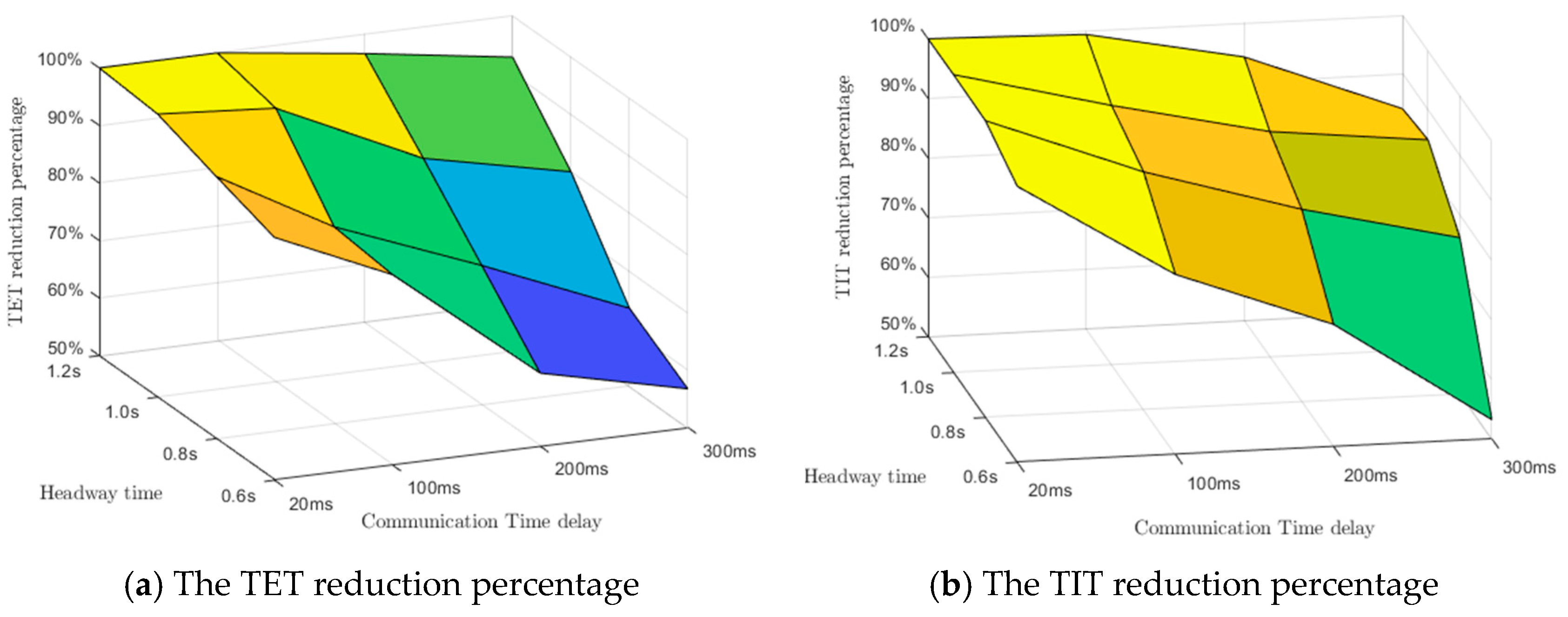
The headway time not only has great effects on traffic efficiency, but also influences the longitudinal safety of CACC vehicles. In the sensitivity analysis experiments, the headway time constant is considered as a key parameter to affect the longitudinal safety of the various CACC platoons. Hence, four values of the headway time gap, including 1.2 s, 1.0 s, 0.8 s, and 0.6 s, are selected as the comparative variables in the sensitivity analysis experiments. In order to quantitatively analyze the rear-end collision risk of in various CACC system, the TIT and TET change percentages are calculated as the evaluation indicator. The specific results are shown in Table 3.
To investigate the longitudinal safety impacts of the communication time delay to the CACC vehicle, CACC systems based on various communication systems were simulated in the sensitivity analysis experiments. According to the previous research literature, four representative vehicular communication ways were analyzed in this section. The time delays 300 ms, 200 ms, 100 ms, and 20 ms correspond to the latency of DSRC, LTE-4G, Hybrid network, and the 5G network, respectively. Besides, the ACC platoon without wireless communication was used as a benchmark for comparing the performances of various CACC systems.
The sensitivity analysis results are shown in Table 3 and Figure 7. From these results, we can see that when the headway time gap is over 1 s, the various CACC controllers all performed excellently without significant difference, especially the hybrid LTE-DSRC CACC and the 5G-CACC, both of which can almost 100% eliminate the rear-end collision risks in the tested experimental scenarios. This indicates that the larger the headway time gap constant, the weaker the communication latency influence on CACC vehicles’ longitudinal safety performance.
With the time gap decreasing, the influence of communication latency becomes gradually more significant. As illustrated in Figure 7, when the headway time constant decreased to 0.8 s, the TET and TIT reduction percentage of the DSRC-CACC and LTE-CACC systems decreased more significantly than the 5G-CACC system. Specifically, as the Figure 7a displays, compared with the ACC system, when the headway time gap decreased to 0.8 s, the 5G-CACC can still reduce about 96% of rear-end collision risks, while the hybrid LTE-DSRC CACC, the LTE-CACC, and the pure DSRC-CACC system can only reduce about 85%, 74%, and 60% rear-end collision risks, respectively. This demonstrates that the extremely low latency, as one of the unique characteristics of the 5G communication system, shows significant advantages in reducing the rear-end collision risks of the CACC platoon. The sensitivity analysis results also suggested that, compared with the sensor-based ACC system, the CACC system based on various wireless communication showed its advantage in enhancing the longitudinal vehicle safety, which is consistent with the previous major study.
From the sensitivity analysis results, we can also conclude that the CACC vehicle based on different wireless communication has different minimal headway time gaps. The CACC system relies on dedicated short-range communications (DSRC) and the long term evolution (LTE) can just function well when the desired headway time is over 1.0 s. Even the hybrid-network can just work well when the headway time is no less than 0.8 s. It is proved that the modified CACC control algorithm with the support of 5G wireless communication can narrow the desired minimal headway time to 0.6 s without significantly increasing the longitudinal rear-end collision risk. The sensitivity analysis results suggest that communication delay is crucial for the CACC platoon performance. This supports the hypothesis that the 5G-CACC system with extremely low communication latency has significant advantages for improving traffic efficiency and reducing rear-end collision risks.

6. Conclusions and Recommendations

This article mainly aimed to investigate the longitudinal safety impacts of the communication time delay on CACC platoons. The safety impacts were measured by the surrogate safety measures of the TIT and TET indicators. A modified CACC vehicle control algorithm accounting for communication latency is proposed in this paper. To verify the feasibility of the proposed control algorithm, we compared the performance of the PATH ACC algorithm and the modified CACC by the simulation experiments. The obtained comparative experimental results reveal that the modified CACC control algorithm can not only dramatically reduce the inter-vehicle spacing error in the platoon, but also enhance the string stability of the CACC vehicle.
Furthermore, to quantitatively evaluate the longitudinal safety impacts of communication latency to the modified CACC system, the CACC platoon constructed, based on DSRC, LTE, and the hybrid DSRC-LTE, were investigated, respectively, in the sensitivity analysis experiments. The sensitivity analysis results suggest that the performance of the platoon is strictly related to the applied wireless communication style. Compared with other kinds of communication systems, the experimental results suggest that the new 5G-CACC system with extremely low communication latency has significant advantages in reducing the rear-end crash risks, especially when the headway time of the CACC platoon decreased to 0.6 s. With the commercial application of the 5G communication network, the unique features of 5G, such as the extremely low latency and ubiquitous connectivity, bring opportunities for the development of the CACC system. It is expected that road safety and traffic efficiency can be enhanced with the combination of different communication technologies in the future.
In this research, only the longitudinal safety impacts, the rear-end collision risks of the CACC platoon, were analysed. In fact, the application of new vehicular communication technologies may also benefit the cooperation of lane change behavior of vehicles on a freeway. Cooperative lane change is another challenging research field. On the other hand, another feature of CACC not considered in this research is CACC longitudinal stability, which is always a key area of CACC research. Furthermore, vehicle-to-vehicle communications can be affected by many external conditions, such as the weather and driver factors, which can significantly impact the results as well. The authors recommend that further research focuses on these issues.

Author Contributions

Conceptualization, Y.L. and W.W.; Formal analysis, Y.L.; Methodology, Y.L. and X.H.; Project administration, W.W.; Resources, Y.L.; Software, Y.L. and W.W.; Visualization, Y.L.; Writing—original draft, Y.L. and X.H.; Writing—review and editing, Y.L. and S.W. All authors have read and agreed to the published version of the manuscript.

Funding

This research was supported by National Natural Science Foundation of China (no. 51878166).

Acknowledgments

The authors are grateful to reviewers for their constructive comments.

Conflicts of Interest

The authors declare no conflict of interest.

References

  1. 2018 CMV Traffic Safety Fact Sheet, 2018, USDOT, Washington, DC, USA. Available online: https://www.fmcsa.dot.gov/safety/data-and-statistics/2018-cmv-traffic-safety-fact-sheet (accessed on 1 August 2019).
  2. Driggs-Campbell, K.; Shia, V.; Bajcsy, R. Improved driver modeling for human-in-the-loop vehicular control. In Proceedings of the 2015 IEEE International Conference on Robotics and Automation (ICRA), Washington, DC, USA, 26–30 May 2015; pp. 1654–1661. [Google Scholar]
  3. Dey, K.C.; Yan, L.; Wang, X.; Wang, Y.; Shen, H.; Chowdhury, M.; Yu, L.; Qiu, C.; Soundararaj, V. A Review of Communication, Driver Characteristics, and Controls Aspects of Cooperative Adaptive Cruise Control (CACC). IEEE Trans. Intell. Transp. Syst. 2016, 17, 491–509. [Google Scholar] [CrossRef]
  4. Panwar, N.; Sharma, S.; Singh, A.K. A survey on 5G: The next generation of mobile communication. Phys. Commun. 2016, 18, 64–84. [Google Scholar] [CrossRef] [Green Version]
  5. Agiwal, M.; Roy, A.; Saxena, N. Next Generation 5G Wireless Networks: A Comprehensive Survey. IEEE Commun. Surv. Tutor. 2016, 18, 1617–1655. [Google Scholar] [CrossRef]
  6. Oncu, S.; Ploeg, J.; Van De Wouw, N.; Nijmeijer, H. Cooperative Adaptive Cruise Control: Network-Aware Analysis of String Stability. IEEE Trans. Intell. Transp. Syst. 2014, 15, 1527–1537. [Google Scholar] [CrossRef] [Green Version]
  7. Milanes, V.; Villagra, J.; Perez, J.; Gonzalez, C. Low-Speed Longitudinal Controllers for Mass-Produced Cars: A Comparative Study. IEEE Trans. Ind. Electron. 2012, 59, 620–628. [Google Scholar] [CrossRef]
  8. Li, S.E.; Zheng, Y.; Li, K.; Wu, Y.; Hedrick, J.K.; Gao, F.; Zhang, H. Dynamical Modeling and Distributed Control of Connected and Automated Vehicles: Challenges and Opportunities. IEEE Intell. Transp. Syst. Mag. 2017, 9, 46–58. [Google Scholar] [CrossRef]
  9. Xu, L.; Wang, L.Y.; Yin, G.; Zhang, H. Communication Information Structures and Contents for Enhanced Safety of Highway Vehicle Platoons. IEEE Trans. Veh. Technol. 2014, 63, 4206–4220. [Google Scholar] [CrossRef]
  10. Rajamani, R.; Shladover, S.E. An experimental comparative study of autonomous and co-operative vehicle-follower control systems. Transp. Res. Part C Emerg. Technol. 2001, 9, 15–31. [Google Scholar] [CrossRef]
  11. Darbha, S.; Rajagopal, K.R. Intelligent cruise control systems and traffic flow stability. Transp. Res. Part C Emerg. Technol. 1999, 7, 329–352. [Google Scholar] [CrossRef] [Green Version]
  12. Zhou, Y.; Ahn, S.; Chitturi, M.; Noyce, D.A. Rolling horizon stochastic optimal control strategy for ACC and CACC under uncertainty. Transp. Res. Part C Emerg. Technol. 2017, 83, 61–76. [Google Scholar] [CrossRef]
  13. Ochocki, M.; Vukadinovic, V.; Januszewski, M.; De La Iglesia, I. Demo: Communication requirements of CACC for high-density platooning. In Proceedings of the 2016 IEEE Vehicular Networking Conference (VNC), Columbus, OH, USA, 8–10 December 2016; IEEE; pp. 1–2. [Google Scholar]
  14. Mir, Z.H.; Filali, F. LTE and IEEE 802.11p for vehicular networking: A performance evaluation. Eurasip J. Wirel. Commun. Netw. 2014, 89. [Google Scholar] [CrossRef] [Green Version]
  15. Rajput, N.S. Measurement of IEEE 802.11p Performance for Basic Safety Messages in Vehicular Communications. In Proceedings of the 2018 IEEE International Conference on Advanced Networks and Telecommunications Systems (ANTS), Indore, India, 16–19 December 2018; IEEE: New York, NY, USA, 2018; pp. 1–4. [Google Scholar]
  16. Wang, Y.; Hu, J.; Zhang, Y.; Xu, C. Reliability Evaluation of IEEE 802.11p-Based Vehicle-to-Vehicle Communication in an Urban Expressway. Tsinghua Sci. Technol. 2015, 20, 417–428. [Google Scholar] [CrossRef]
  17. Charitos, M.; Kalivas, G. MIMO HetNet IEEE 802.11p–LTE deployment in a vehicular urban environment. Veh. Commun. 2017, 9, 222–232. [Google Scholar] [CrossRef]
  18. Vinel, A. 3GPP LTE Versus IEEE 802.11p/WAVE: Which Technology is Able to Support Cooperative Vehicular Safety Applications? IEEE Wirel. Commun. Lett. 2012, 1, 125–128. [Google Scholar] [CrossRef] [Green Version]
  19. Möller, A.; Baumgarten, J.; Hameed Mir, Z.; Filali, F.; Kürner, T. Realistic simulation scenario for hybrid LTE/IEEE 802.11p vehicular communication, in 2015 9th European Conference on Antennas and Propagation (EuCAP). In Proceedings of the 2015 9th European Conference on Antennas and Propagation (EuCAP), Lisbon, Portugal, 12–17 April 2015; pp. 1–5. [Google Scholar]
  20. Ateya, A.A.; Muthanna, A.; Makolkina, M.; Koucheryavy, A. Study of 5G Services Standardization: Specifications and Requirements. In Proceedings of the 2018 10th International Congress on Ultra Modern Telecommunications and Control Systems and Workshops (ICUMT), Moscow, Russia, 5–9 November 2018; IEEE: New York, NY, USA, 2018; pp. 1–6. [Google Scholar]
  21. Service Requirements for Next Generation New Services and Markets. In 3GPP, Technical Specification TS 22.261. 2017. Available online: https://www.tech-invite.com/index.html (accessed on 1 August 2020).
  22. Balasubramanian, V.; Otoum, S.; Aloqailyb, M.; Al Ridhawi, I.; Jararweh, Y. Low-latency vehicular edge: A vehicular infrastructure model for 5G. Simul. Model. Pract. Theory 2020, 98, 101968. [Google Scholar] [CrossRef]
  23. Sachs, J.; Andersson, L.A.A.; Araujo, J.; Curescu, C.; Lundsjo, J.; Rune, G.; Steinbach, E.; Wikstrom, G. Adaptive 5G Low-Latency Communication for Tactile InternEt Services. Proc. IEEE 2019, 107, 325–349. [Google Scholar] [CrossRef]
  24. Study on Communication for Automation in Vertical Domains (CAV). In 3GPP, Technical Specification TS 22.804. 2017. Available online: https://www.tech-invite.com/x0/tinv-ietf-rfcs-88.html (accessed on 1 August 2020).
  25. Wischhof, L.; Ebner, A.; Rohling, H. Information Dissemination in Self-Organizing Intervehicle Networks. IEEE Trans. Intell. Transp. Syst. 2005, 6, 90–101. [Google Scholar] [CrossRef]
  26. Cseh, C. Architecture of the dedicated short-range communications (DSRC) protocol. In Proceedings of the VTC ’98. 48th IEEE Vehicular Technology Conference—Pathway to Global Wireless Revolution (Cat. No.98CH36151), Ottawa, ON, Canada, 21 May 1998; Volume 3, pp. 2095–2099. [Google Scholar]
  27. Liang, W.; Li, Z.; Zhang, H.; Wang, S.; Bie, R. Vehicular Ad Hoc Networks: Architectures, Research Issues, Methodologies, Challenges, and Trends. Int. J. Distrib. Sens. Netw. 2015, 11, 745303. [Google Scholar] [CrossRef]
  28. Milanés, V.; Shladover, S.E. Modeling cooperative and autonomous adaptive cruise control dynamic responses using experimental data. Transp. Res. Part C: Emerg. Technol. 2014, 48, 285–300. [Google Scholar]
  29. Milanes, V.; Shladover, S.E.; Spring, J.; Nowakowski, C.; Kawazoe, H.; Nakamura, M. Cooperative Adaptive Cruise Control in Real Traffic Situations. IEEE Trans. Intell. Transp. Syst. 2014, 15, 296–305. [Google Scholar] [CrossRef] [Green Version]
  30. Nieuwenhuijze, M.R.I.; Van Keulen, T.; Oncu, S.; Bonsen, B.; Nijmeijer, H. Cooperative Driving With a Heavy-Duty Truck in Mixed Traffic: Experimental Results. IEEE Trans. Intell. Transp. Syst. 2012, 13, 1026–1032. [Google Scholar] [CrossRef]
  31. Treiber, M. Sample Chapter 11 on Car-Following Models based on Driving Strategies. In Traffic Flow Dynamics; Springer: Berlin/Heidelberg, Germany, 2013; pp. 181–204. [Google Scholar]
  32. Kesting, A.; Treiber, M.; Helbing, D. Enhanced intelligent driver model to access the impact of driving strategies on traffic capacity. Philos. Trans. R. Soc. A 2010, 368, 4585–4605. [Google Scholar] [CrossRef] [PubMed] [Green Version]
  33. Hult, R.; Sancar, F.E.; Jalalmaab, M.; Vijayan, A.; Severinson, A.; Di Vaio, M.; Falcone, P.; Fidan, B.; Santini, S. Design and Experimental Validation of a Cooperative Driving Control Architecture for the Grand Cooperative Driving Challenge 2016. IEEE Trans. Intell. Transp. Syst. 2018, 19, 1290–1301. [Google Scholar] [CrossRef]
  34. Ding, J.; Pei, H.; Hu, J.; Zhang, Y. Cooperative Adaptive Cruise Control in Vehicle Platoon under Environment of i-VICS. In Proceedings of the 2018 21st International Conference on Intelligent Transportation Systems (ITSC), Maui, HI, USA, 4–7 November 2018; IEEE: New York, NY, USA, 2018. [Google Scholar]
  35. Sybis, M.; Vukadinovic, V.; Rodziewicz, M.; Sroka, P.; Langowski, A.; Lenarska, K.; Wesolowski, K. Communication Aspects of a Modified Cooperative Adaptive Cruise Control Algorithm. IEEE Trans. Intell. Transp. Syst. 2019, 20, 4513–4523. [Google Scholar] [CrossRef]
  36. Zhao, P.; Lee, C. Assessing rear-end collision risk of cars and heavy vehicles on freeways using a surrogate safety measure. Accid. Anal. Prev. 2018, 113, 149–158. [Google Scholar] [CrossRef]
  37. Hayward, J.C. Near-miss determination through use of a scale of danger. Highw. Res. Rec. 1972, 384, 24–34. [Google Scholar]
  38. Gettman, D.; Head, L. Surrogate Safety Measures from Traffic Simulation Models. Transp. Res. Rec. 2003, 1840, 104–115. [Google Scholar] [CrossRef] [Green Version]
  39. Rahman, M.S.; Abdel-Aty, M. Longitudinal safety evaluation of connected vehicles’ platooning on expressways. Accid. Anal. Prev. 2018, 117, 381–391. [Google Scholar] [CrossRef]
  40. Li, Y.; Li, Z.; Wang, H.; Wang, W.; Xing, L. Evaluating the safety impact of adaptive cruise control in traffic oscillations on freeways. Accid. Anal. Prev. 2017, 104, 137–145. [Google Scholar] [CrossRef]
  41. Tu, Y.; Wang, W.; Li, Y.; Xu, C.; Xu, T.; Li, X. Longitudinal safety impacts of cooperative adaptive cruise control vehicle’s degradation. J. Saf. Res. 2019, 69, 177–192. [Google Scholar] [CrossRef]
  42. Li, Y.; Wang, H.; Wang, W.; Xing, L.; Liu, S.; Wei, X. Evaluation of the impacts of cooperative adaptive cruise control on reducing rear-end collision risks on freeways. Accid. Anal. Prev. 2017, 98, 87–95. [Google Scholar] [CrossRef] [PubMed]
  43. Li, Y.; Xing, L.; Wang, W.; Liang, M.; Wang, H. Evaluating the impact of Mobike on automobile-involved bicycle crashes at the road network level. Accid. Anal. Prev. 2018, 112, 69–76. [Google Scholar] [CrossRef] [PubMed]
  44. Li, Y.; Wang, W.; Xing, L.; Fan, Q.; Wang, H. Longitudinal safety evaluation of electric vehicles with the partial wireless charging lane on freeways. Accid. Anal. Prev. 2018, 111, 133–141. [Google Scholar] [CrossRef] [PubMed]
  45. Li, Y.; Wang, H.; Wang, W.; Liu, S.; Xiang, Y. Reducing the risk of rear-end collisions with infrastructure-to-vehicle (I2V) integration of variable speed limit control and adaptive cruise control system. Traffic Inj. Prev. 2016, 17, 597–603. [Google Scholar] [CrossRef] [PubMed]
  46. Xu, C.; Tarko, A.P.; Wang, W.; Liu, Z.-H. Predicting crash likelihood and severity on freeways with real-time loop detector data. Accid. Anal. Prev. 2013, 57, 30–39. [Google Scholar] [CrossRef]
  47. Standard International Organization For Standardization, Intelligent Transport Systems–Adaptive Cruise Control Systems–Performance Requirements and Test Procedures. In ISO Standard 15622; Artech House: London, UK, 2010.
Figure 1. The ACC control system schematic.
Sustainability 12 07568 g001
Figure 2. The CACC communication based on DSRC system.
Sustainability 12 07568 g002
Figure 3. CACC system based on 5G communication system.
Sustainability 12 07568 g003
Figure 4. Illustration of the microscopic simulation testbed.
Sustainability 12 07568 g004
Figure 5. Performance of the ACC vehicles.
Sustainability 12 07568 g005
Figure 6. Performance of the CACC vehicles under the designed test scenario.
Sustainability 12 07568 g006
Figure 7. Results of sensitivity analysis.
Sustainability 12 07568 g007
Table 1. Table of basic safety information exchange.
Information ItemUnit
Longitudinal position ( x k ) m
Current velocity ( v k ) m / s
Real-time acceleration ( a k ) m / s 2
Table 2. Table of CACC model parameters.
Corrective CoefficientValues
Acceleration gains ( λ a )0.2
Velocity error ( λ v )0.75
Spacing gap error ( λ g )0.25
Table 3. Sensitivity analysis of headway time of CACC vehicles.
Controller
TCC* = 3 s
Latency
(ms)
T g a p = 1.2 s T g a p = 1.0 s T g a p = 0.8 s T g a p = 0.6 s
TETTITTETTITTETTITTETTIT
DSRC-CACC30092.2%84.3%83.1%85.1%62.7%76.2%56.7%53.2%
LTE-CACC20095.6%94.3%84.2%87.8%74.2%82.3%63.5%70.5%
Hybrid-CACC10099.2%99.4%97.6%93.5%85.6%89.9%79.99%80.2%
5G-CACC20100%100%100%100%96.6%99.8%92.7%96.3%
Note: the ACC vehicles without communication systems were used as a reference in the simulation results.

