Article

Study on Evolutionary Characteristics of Toppling Deformation of Anti-Dip Bank Slope Based on Energy Field

1
College of Civil Engineering and Architecture, Xinjiang University, Urumqi 830046, Xinjiang, China
2
Department of Geotechnical Engineering, Tongji University, Shanghai 200092, China
*
Author to whom correspondence should be addressed.
Sustainability 2020, 12(18), 7544; https://doi.org/10.3390/su12187544
Submission received: 22 July 2020 / Revised: 6 September 2020 / Accepted: 7 September 2020 / Published: 13 September 2020
(This article belongs to the Special Issue Geo-Hazards and Risk Reduction Approaches)

Abstract

:
The evolution of toppling deformation of anti-dip slope is essentially a process of energy dissipation and transformation. Aiming to study the characteristics of energy evolution in different stages, the DEM (discrete element method) software PFC (Particle Flow Code) was utilized to establish a two-dimensional numerical model for a bank slope in Chongqing based on geological background data and field investigation. The DEM model was proven to be reliable not only because the deformation discrepancy between the numerical model and actual bank slope was not large but also because some obvious fractures in the actual bank slope can readily be found in the numerical model as well. In this article, content about displacement in the shallow layer was analyzed briefly. Special effort was made to analyze the energy field and divide the toppling deformation process into three stages. (1) Shear deformation stage: this is an energy accumulating stage in which the strain energy, friction energy, and kinetic energy are all small and the deformation is mainly shear deformation in the slope toe. (2) Stage of main toppling fracture surface hole-through: all three kinds of energy present the increasing trend. The shear deformation in the slope toe expands further, and the toppling deformation also appears in the middle and rear parts of the bank slope. (3) Stage of secondary toppling and fracture surface development: strain energy and friction energy increase steadily but kinetic energy remains constant. Deformation consists mainly of secondary shearing and a fracture surface in the shallow layer. Secondary toppling and fracture surface develop densely.

1. Introduction

According to statistics, 33% of slope deformation occurs in the anti-dip slope, and most large or huge slope deformation failure usually occurs in the anti-dip slope [1]. A large number of engineering examples indicated that the obvious feature in the failure of anti-dip slope was that the formation of the flexural fracture surface needed a long incubation process, but once this kind of slope was unstable, the extent of the damage was severe and would cause catastrophic failure [1]. Therefore, it is necessary to study the evolutionary characteristics of deformation of this kind of slope, and many scholars have utilized information about the strain and stress fields in the deformation process in order to study evolutionary characteristics [2,3,4,5,6,7,8,9,10,11,12,13,14]. The mechanism of flexural toppling failure of jointed rock slope was investigated by centrifuge tests. The basal failure plane oriented at an angle of 12 to 20 degrees was found to emanate from the slope toe, and a theoretical model based on limiting equilibrium was utilized to analyze the experimental data, which was subsequently proven to have good accuracy [15]. The numerical simulation software 3DEC (3 Dimension Distinct Element Code) was used to study the toppling deformation mechanism, founding the assumption that the slope was continuous and setting to be constant in the two-dimensional case would make a significant difference when it is applied in the three-dimensional case, and the dip direction of the toppling discontinuity set was shown to clearly influence slope failure and stability [16]. Wu et al. [17] used the three-dimensional DDA (Discontinuous Deformation Analysis) method to study the deformation and failure mechanism of a local anti-dip slope in Amatoribashi, Japan, and finally found a new calculation approach which could predict the rock mass instability process. Gschwind et al. [18] analyzed a slope in Preonzo of Switzerland with the multi-stage structural and kinetic method and found that planar or wedge sliding is the preferred kinematic mode. Alejano et al. [19] studied the failure mechanism of a workbench with 30 m height and considered that the reason for its instability was that a slender rock mass in the middle area overwhelmed the rock mass in the lower part, resulting in the increasing damage. Xu et al. [20] utilized the microseismic (MS) monitoring system to detect failure in a rock slope under long-term, continuous excavation and then used a numerical simulation method to study the bank slope deformation and failure mechanism. Simulation data agreed well with the monitoring data, all of them indicating that the deformation and failure characteristics of the rock slope were mainly controlled by the pre-existing weak structural plane. Wu et al. [21] made use of a composite fiber device in rock slope monitoring. The evolution process of rock slope sliding was divided into three stages: the compression stage, uniform velocity deformation stage, and acceleration stage. Zhang et al. [22] conducted a comprehensive analysis of the deformation mechanism of anti-dip slope and divided the evolution process into four phases: bending tensile, bending fracture, sliding tensile crack deformation, and ground subsidence and deep sliding. Li et al. [23] integrated the shear strength reduction method (SSR) and a novel continuum-based discrete element method (CDEM) to carry out a numerical simulation with a large-scale open-pit rock slope with typical anti-dip joint in Fushun. Deformation characteristics and the failure process in simulation agreed well with data obtained from radar, and the evolutionary process from stable to unstable was divided into three stages: stable state, development, and initial failure state.
In summary, most of the scholars studied toppling deformation in view of stress or strain, and analysis with respect to energy is relatively rare. However, the slope deformation process is essentially a process of energy evolution, and the same amount of energy can not only present large area deformation but also can present small area deformation. From above, the universality of existing research is relatively poor, and the evolutionary characteristics of toppling deformation need to be studied in view of the energy field.

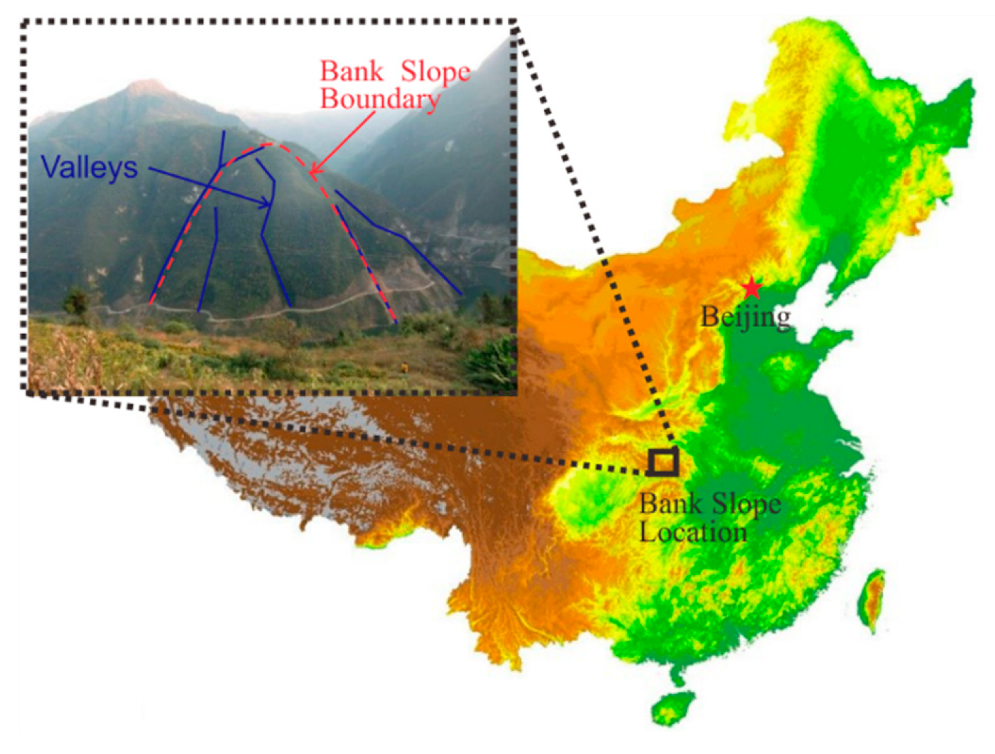
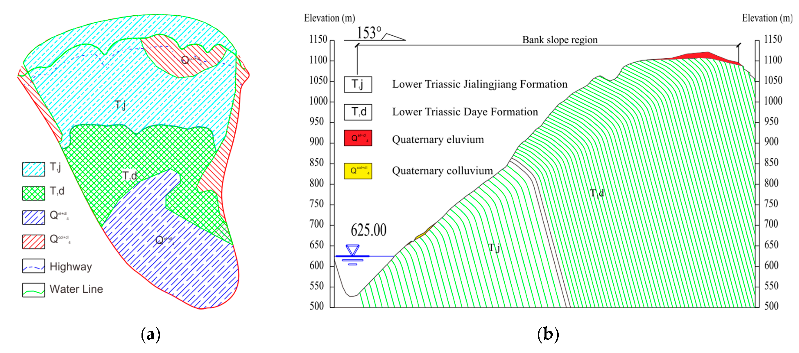
2. Geological Background of the Bank Slope

2.1. Engineering Overview

Shown in Figure 1, the Xiaodongcao bank slope is located in the right bank of the upper Xixi River in Zhongliang, Wuxi County, Chongqing. The slope height is around 526 to 1183 m; width is around 700 m. The middle front section of the slope is quite steep, and the slope angle is around 45 to 68 degrees; the rear section is relatively gentle, and the slope angle is around 11 to 18 degrees. The research region belongs to the middle and lower mountain karst geomorphology unit, generally high in the south and low in the north. The main mountain ranges are arranged along the tectonic line, and the river between mountains cuts deeply. The height difference in the river valley and mountain on both sides can reach 800 to 1000 m.
Shown in Figure 2a, field investigation indicated that the bank slope is made up of Jialingjiang formation and Daye formation of lower Triassic nature. The front part is Jialingjiang formation, with thin to medium thick layered dolomite limestone (T1j); the middle and rear part is Daye formation, with thin to medium thick layered argillaceous limestone (T1d). As presented in Figure 2b, strata in the slope topple and most of the occurrences are 185°∠82°. Regarding the influence of flexural toppling deformation, the change in the rock strata inclination in the affected area is around 20 to 75 degrees.

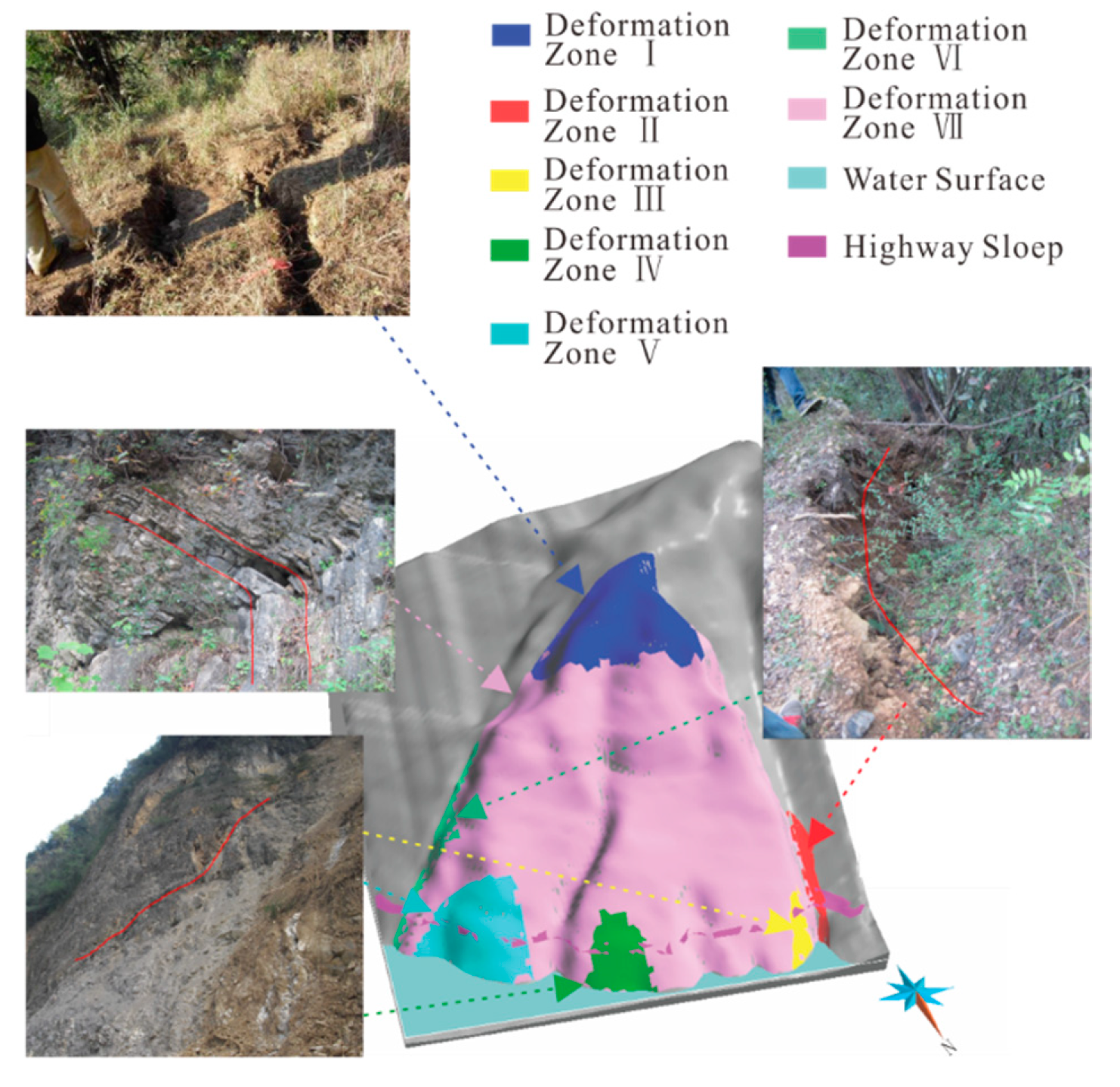
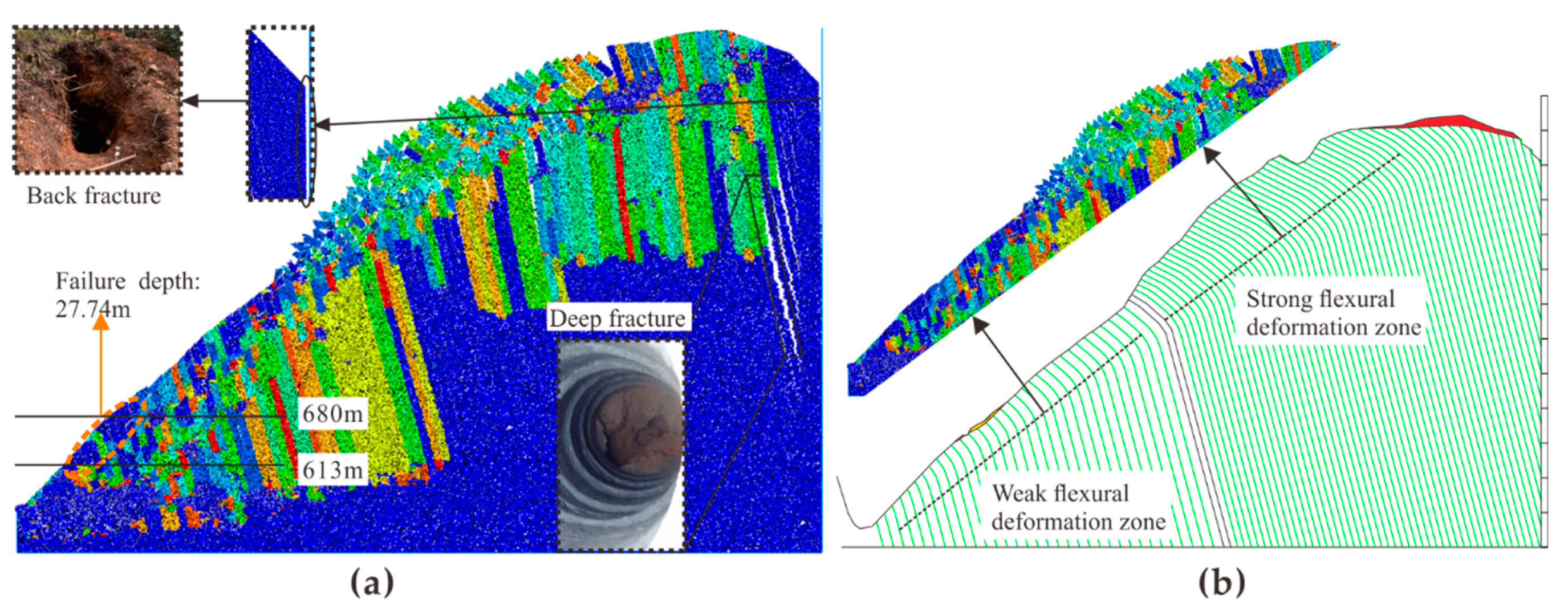
2.2. Regionalization of Surface Deformation of the Bank Slope

Since the Zhongliang reservoir began to impound in January 2011, local deformation failure phenomena with different scales began to occur in the Xiaodongcao bank slope. Main deformation types in the affected area are fractures in the trailing edge, house cracking, many tensile fractures along the highway, and large areas of collapse which occurred on both sides of the valleys.
The investigation of the engineering geological environment showed that the essence of the bank slope is a flexural toppling deformation body. Without the influence of human engineering, the bank slope had good stability, even though there was already some weak deformation. However, toppling deformation is aggravated into severe deformation due to the influence of reservoir construction and excavation of highway slopes. According to the investigation of surface deformation, the bank slope body was divided into seven deformation zones, as presented in Figure 3.
According to the investigation of the surface geological deformation, the deformation and failure characteristics of each zone were statistically analyzed (Table 1). Shown in Figure 3 and Table 1, obvious deformation zones were distributed in the front part and rear part of the bank slope and mainly were surficial tensile fractures, slide of colluvium, and flexural fracture of rock strata.

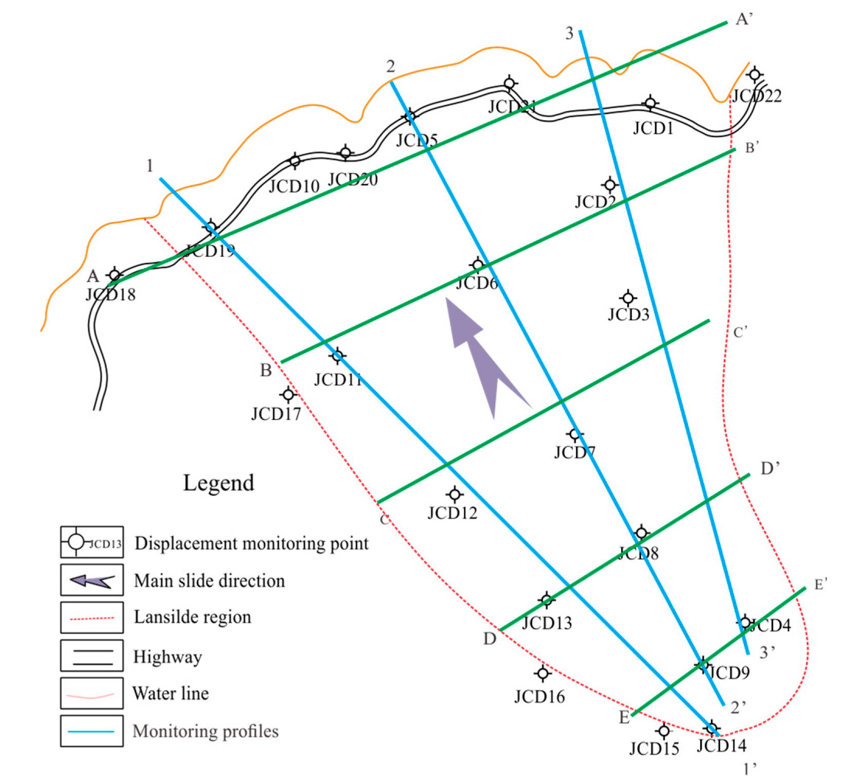
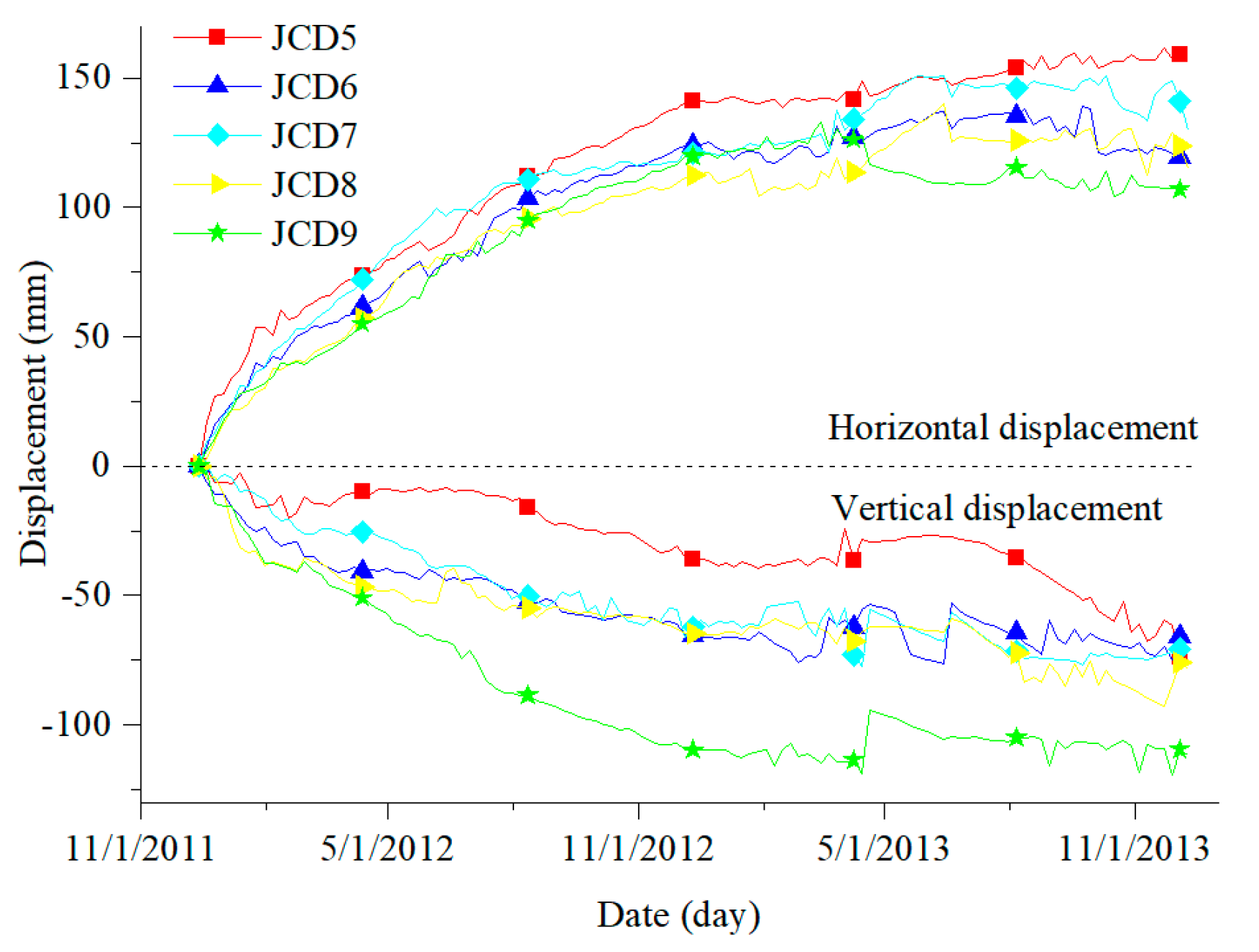
2.3. Monitoring System

(1) Arrangement of monitoring system
As shown in Figure 4, the monitoring system of the displacement of the Xiaodongcao bank slope is composed of 22 surface displacement monitoring points and 3 deep monitoring points. Monitoring points of surface displacement were evenly distributed in the whole research area, 17 of them set in the bank slope body and 5 of them set in the bank slope boundary. Monitoring points of deep displacement were installed along the middle line of the bank slope at the middle front part, middle rear part, and rear part of the bank slope, respectively.
Monitoring started in December 2011 and ended in December 2013. For the feature of the arrangement of the monitoring system, we obtained five cross-sections and three longitudinal profiles, as indicated in Figure 4. Since the subsequent numerical model of the bank slope will be made on the basis of the 2-2′ profile (middle line), only displacement in the middle line will be introduced for subsequent model verification.
(2) Monitoring displacement of middle line
Monitoring results (Figure 5) obtained from the 2-2′ profile showed that the horizontal displacement gradually decreased from the front to rear part of the bank slope, and vertical displacement increased in the same direction. In the middle line of the bank slope, analysis showed that horizontal displacement (presented in shear deformation) is dominant in the front part; vertical displacement (shown in toppling deformation) is dominant in the rear part.

3. Establishing Engineering Geological Model for Bank Slope

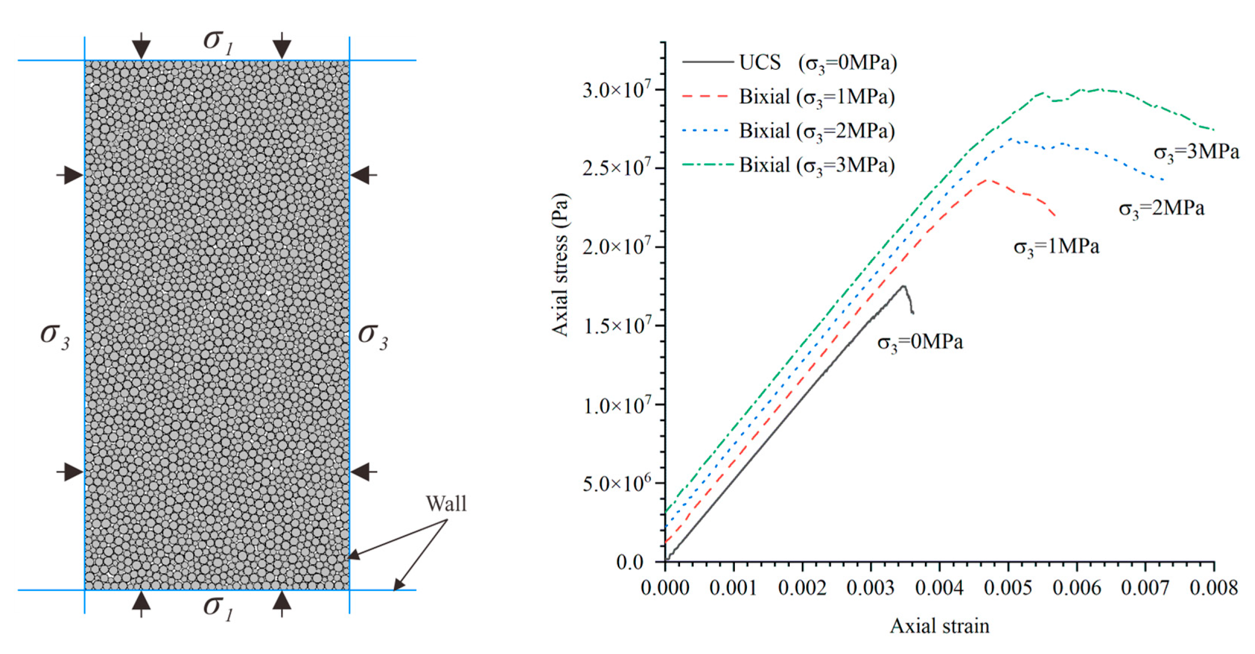
3.1. Parameter Calibration

Particle Flow Code (PFC) is a general calculation and analysis program based on discrete element theory, which is suitable for delineating granular and colloidal material into micro mechanical properties and analyzing stress and deformation.
The numerical model in the two-dimensional case is essentially a combination with lots of disks with thick units. For this, the parameters set in the PFC are microscopic parameters describing the physical features of particles and cemented section. Therefore, microscopic parameters should be determined by numerical rock test in order to ensure that they match the experimental data as much as possible.
A linear contact bond model (CBM) and linear parallel bond model (PBM) are provided in PFC to simulate the cement section between particles. The PBM is selected for its mechanical property by which it can resist moment. This property makes the combination of disks more similar to real rock material. The maximum tensile and shear stress in the cement section are as follows:
σ ¯ m a x = F ¯ n A + | M ¯ s | R ¯ I
τ ¯ m a x = | F ¯ s | A + | M ¯ n | R ¯ J
R ¯ , A, I, and J are the radius, area, moment of inertia, and polar moment of inertia of the cement section, respectively; F ¯ n , F ¯ s , M ¯ n , and M ¯ s are the axial and tangential force and moment. When σ ¯ m a x > σ ¯ c or τ ¯ m a x > τ ¯ c , the cement section will break, where σ ¯ c and τ ¯ c are the tensile strength and shear strength, respectively.
All traditional rock tests can be simulated in PFC, and we can also obtain numerical macroscopic parameters. When numerical macroscopic parameters match well with the real ones, this set of microscopic parameters will be used in the subsequent simulation.
Calibrating microscopic parameters is mainly based on traditional macroscopic parameters like Poisson’s ratio υ, Young’s modulus E, and uniaxial compressive strength σ c . Having already obtained the macro parameters (Table 2), a numerical uniaxial compression test (UCS) and biaxial rock tests (Figure 6) were continuously conducted to calibrate the microscopic parameters based on methods recommended by Itasca and existing research results [24,25,26].
From uniaxial compression tests, uniaxial compressive strength ( σ c ) can be directly observed from the stress–strain curve (Figure 6). Young’s modulus (E) and Poisson’s ratio (υ) can be obtained from Formula (3) and (4) shown below:
E = σ 50 ε l 50
υ = ε d 50 ε l 50
σ 50 represents half of the uniaxial compression strength; ε l 50 and ε d 50 are the axial strain and transverse strain to σ 50 , respectively. Axial stress can be obtained from monitoring the force in walls; axial strain can be measured from displacement of walls.
Cohesion c and internal friction angle φ are obtained by biaxial test under different pressures and the envelope of the Moore stress circles; tension strength ( σ t ) was obtained by tensile test.
Microscopic parameters of two type of rock in the research area are shown in Table 3.

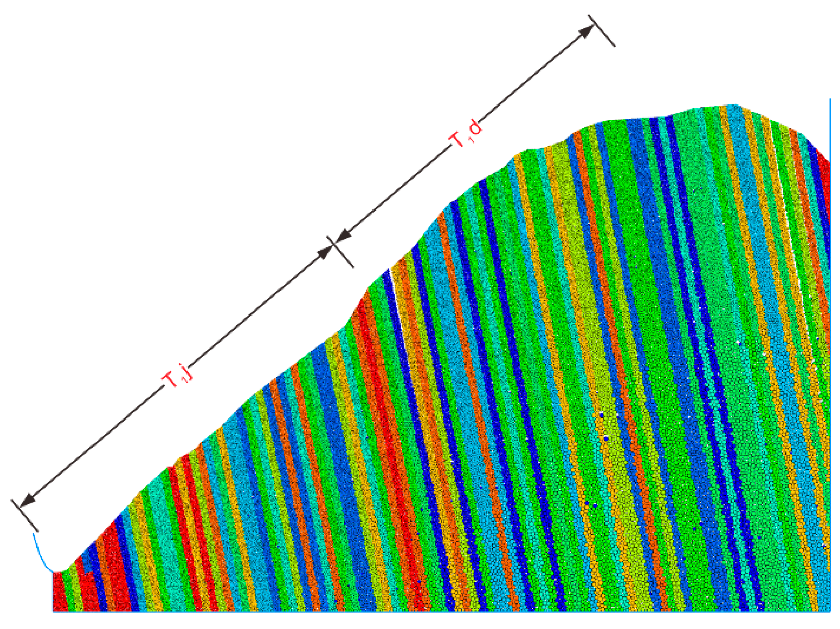
3.2. Model Introduction and Arrangement of Monitoring Points

(1) Model introduction
On the basis of obtaining rock data of the bank slope, the profile of the middle line of the bank slope was chosen for establishing this numerical model. This model contains 102,462 particles (Figure 7), where particles in the area of the joints are bonded by the smooth joint model and others bonded by the parallel bond model. Horizontal displacement in the left and right boundary was fixed, as was the vertical displacement in the bottom boundary.
(2) Arrangement of monitoring points in numerical model
Aiming to obtain the evolutionary characteristics of the displacement field in the deformation process, monitoring points on the numerical model with horizontal spacing of 100 m were arranged at the shallow layer with a depth of 40 m (Figure 8). All of them are named from A to J in the direction from slope toe to slope crest.

3.3. Model Verification

(1) Displacement contrast
We compared the actual displacement monitored in JCD5 (above mentioned in Figure 5) with simulation data obtained from monitoring point C, which also is located in the front part of the bank slope. The horizontal displacement curve obtained from the simulation is shown in Figure 9.
The vertical displacement curve obtained from the simulation is shown in Figure 10.
According to Figure 5, we can determine that the horizontal and vertical displacement of JCD5 at the end of the monitoring time is around 161 and 66 mm, respectively. From Figure 9 and Figure 10, we can see that the simulated horizontal and vertical displacement of monitoring point C is around 223 and 43 mm, respectively, and the difference is 38% and 34%. The difference is possible when we do not take the influence of the groundwater and engineering activities into consideration. The simulated displacement and actual displacement similarly all show an increasing tendency.
(2) Deformation and fractures contrast
After the numerical model iteratively calculating 1 million steps, simulation results (Figure 11a) show that shear failure occurs in the front region of the bank slope and the dip angle change is small; obvious toppling failure occurs in the rear region and the dip angle change is large. The difference in the angle change of strata is consistent with actual deformation characteristics (Figure 11b). Moreover, the 80 m deep fracture revealed by actual well exploration and the back fracture in the trailing edge exposed by trenching can be found in the marked area of Figure 11a.
(3) Contrast with other methods
Cai et al. [27] made use of the cantilever beam limit equilibrium model to study the failure of anti-dip rock slopes. They calculated the depth of the fracture surface of the Xiaodongcao bank slope in elevations from 613 to 680 m and the average failure depth was 23.29 m. Marked with the orange line in Figure 11a, the failure depth is around 27.74 m.
From the above, it is reasonable to assume that the model is dependable.

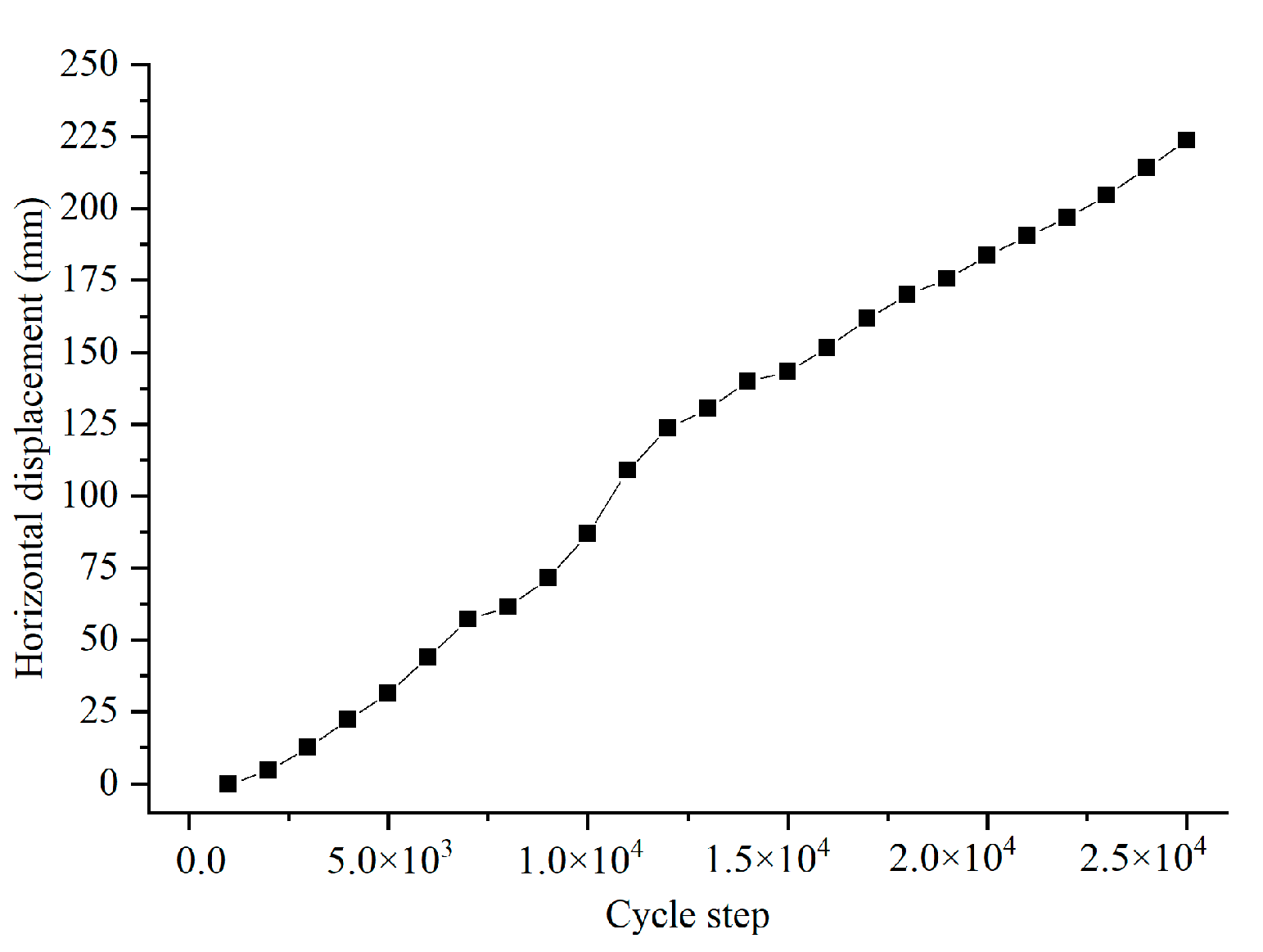
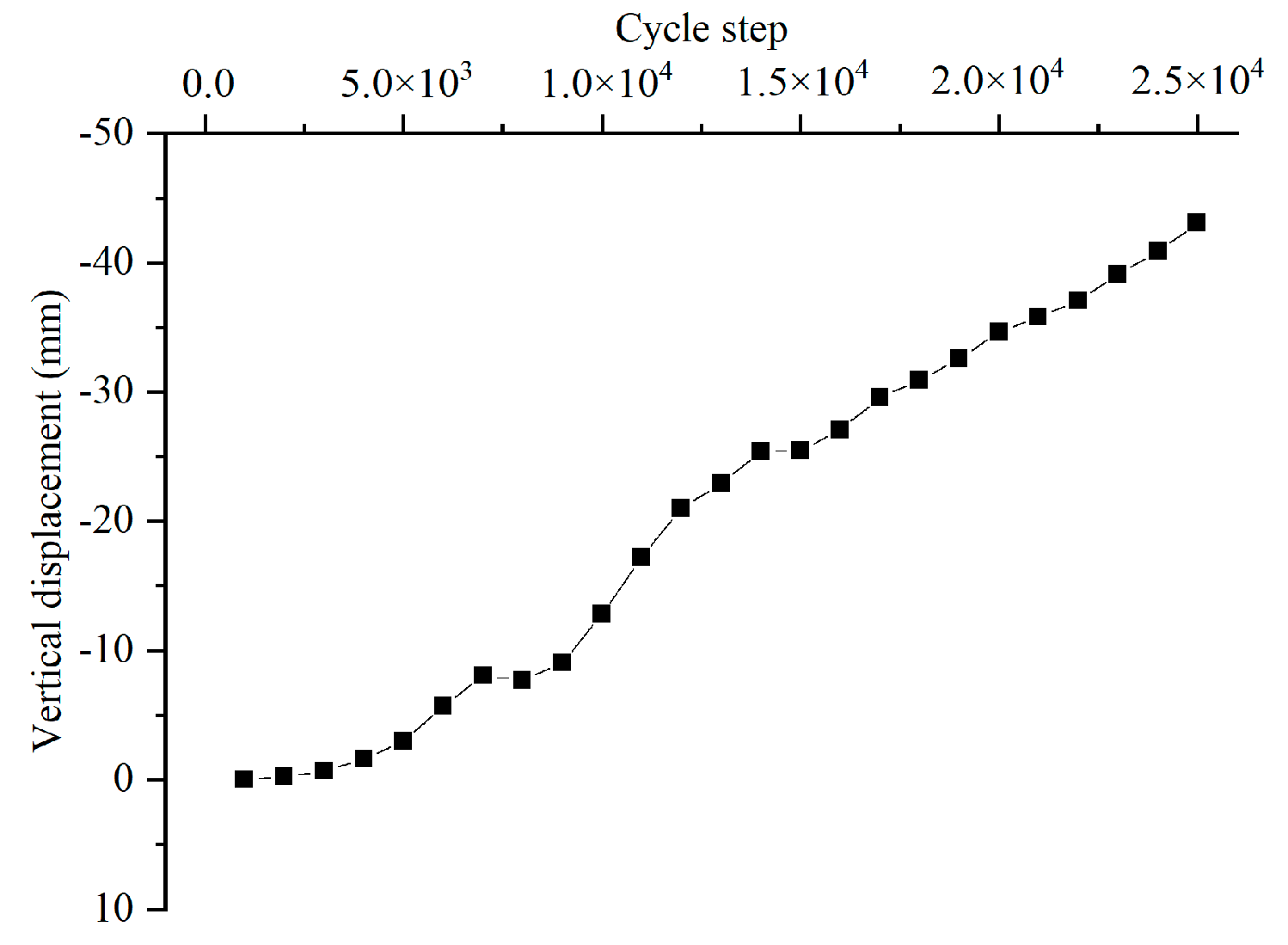
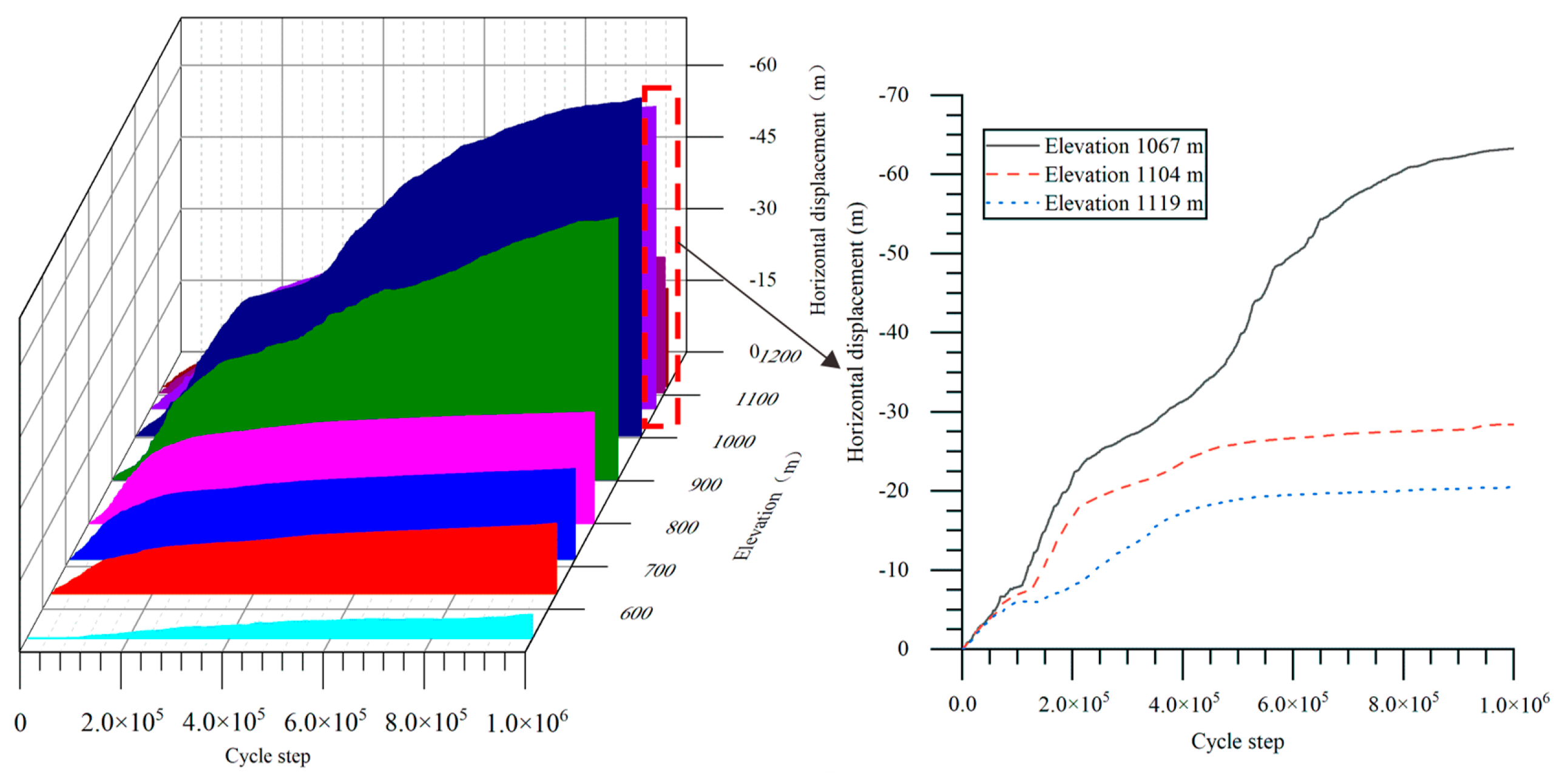
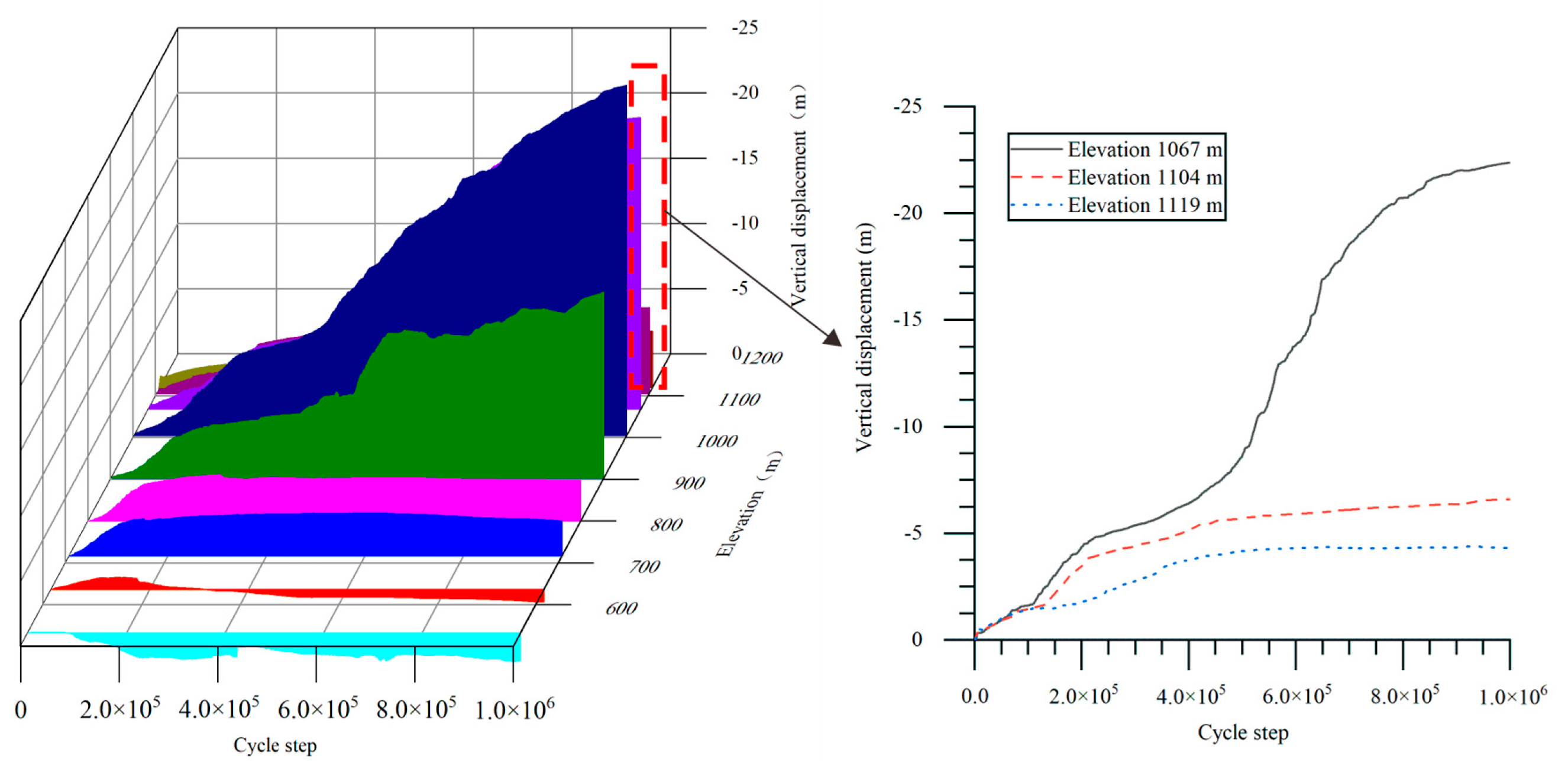
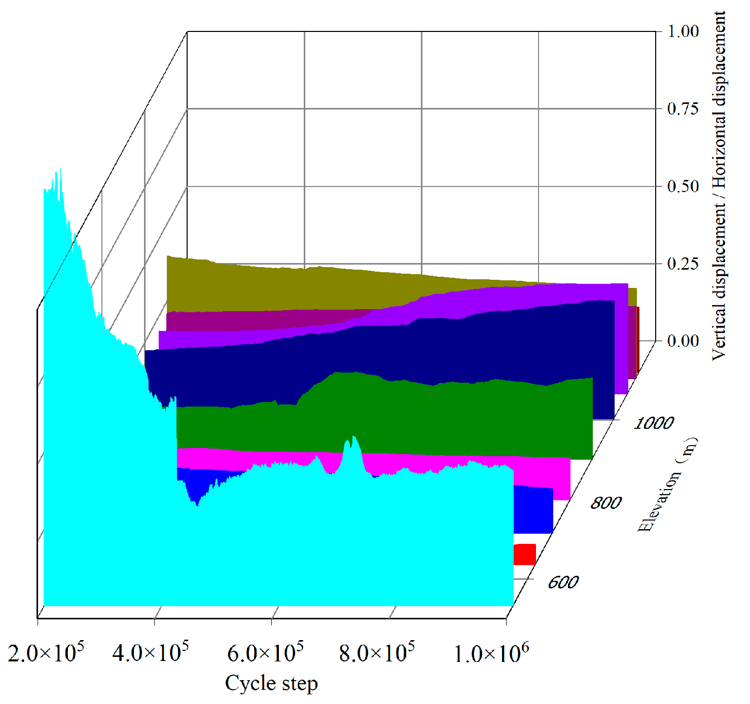
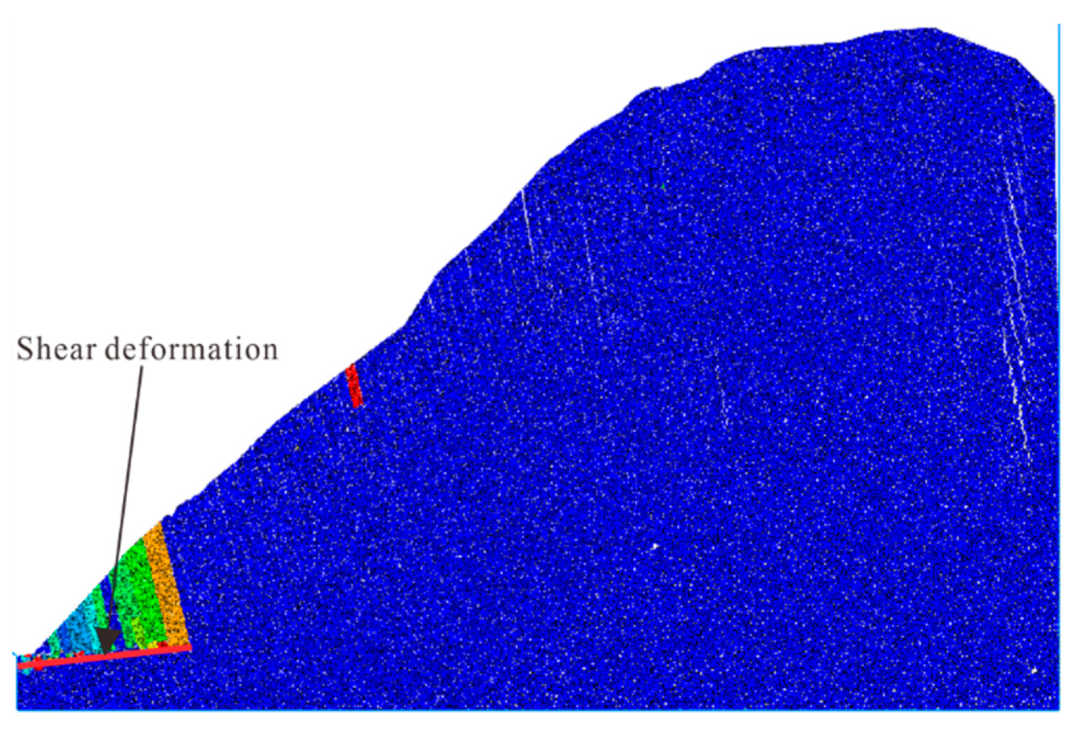
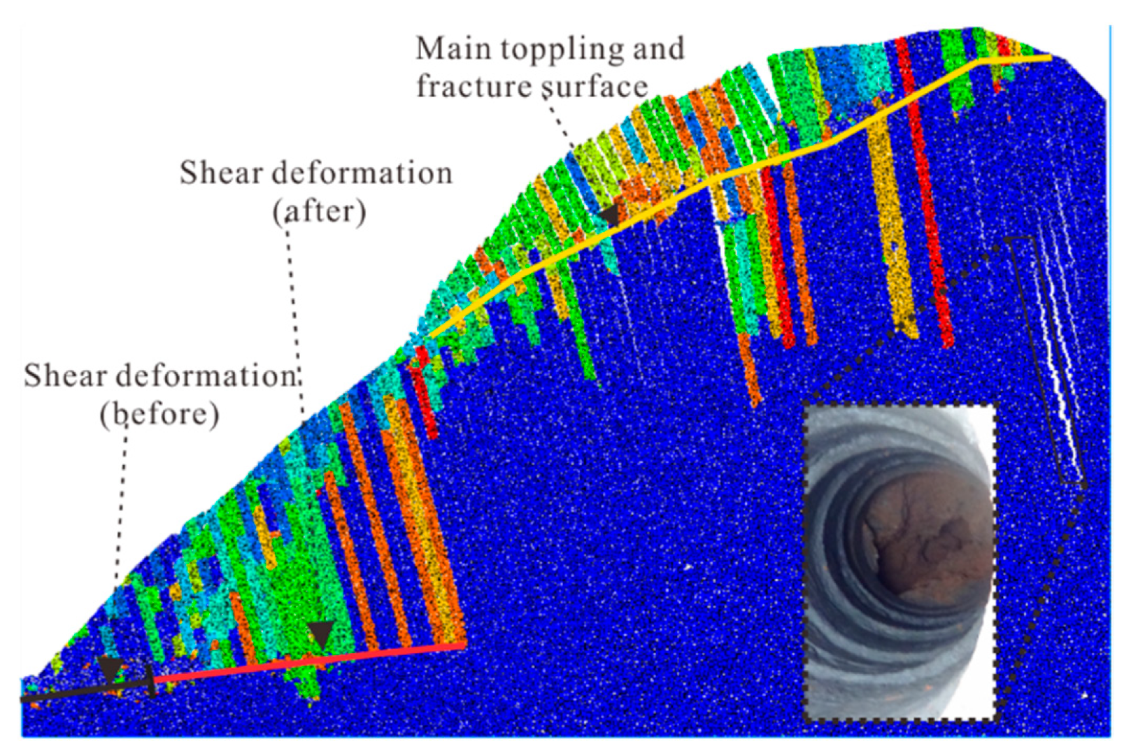
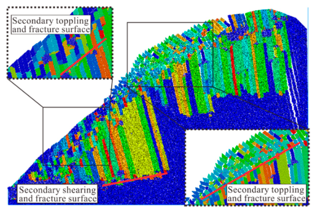
4. Evolutionary Characteristics of Displacement Field

Comparing the difference in shape features of the bank slope before and after the evolution of the toppling deformation (Figure 12), we know that deformation becomes more and more obvious from slope toe to slope crest. Deformation characteristics in various areas can be delineated through the displacement field. The vertical and horizontal displacement will be combined with deformation characteristics to analyze the characteristics of the displacement field in the process of toppling deformation.
Vertical and horizontal displacement curves from monitoring points of the surface were compared and analyzed. Figure 13 indicates that, in the early stage of the evolutionary process, areas with large horizontal displacement are mainly distributed in regions with heights below 800 m, and the deformation increases with cycle steps. It also shows that deformation to the free face occurs on the whole surface of the bank slope. The increasing speed and value of horizontal displacement is the largest in the area with heights of 900 to 1050 m. Then, it gradually decreases in the direction of the slope toe and slope crest, and horizontal displacement at the slope crest is larger compared with that in the slope toe.
Comparing Figure 14 with Figure 13, vertical displacement is smaller with horizontal displacement. Large vertical displacement areas are mainly distributed in regions with heights from 800 to 1100 m. In the front part of the bank slope, vertical displacement is the smallest, and vertical upward displacement occurs in this area in the later stage of the evolutionary process. The vertical upward deformation is related to shearing deformation, which occurs in the front region and causes surficial rock mass in the slope toe to be uplifted.
In Figure 15, the spatial distribution of the ratio of vertical displacement to horizontal displacement in the toppling process was analyzed, from which we see that displacement of the bank slope is mainly composed of horizontal displacement. Vertical displacement in the slope toe is relatively larger for uplift by shearing deformation, and the value of the ratio is larger in the middle and rear parts of the bank slope, meaning that the influence of vertical displacement is stronger than that in the front part. In the evolutionary process, the value of the ratio in the middle part (elevation of around 900 to 1050 m) of the bank slope gradually increases with cycle steps, but the value in the front and rear parts of the slope gradually decrease with cycle steps. The decrease showed that the influence of vertical displacement in the middle section becomes more and more significant in the later stage of the evolutionary process.
Although the evolutionary characteristics of the toppling deformation can be directly and vividly expressed in the displacement field, there are a lot of significant differences in various regions of the slope, so it was hard to establish a unified reference standard for analyzing the evolutionary characteristics of toppling deformation.

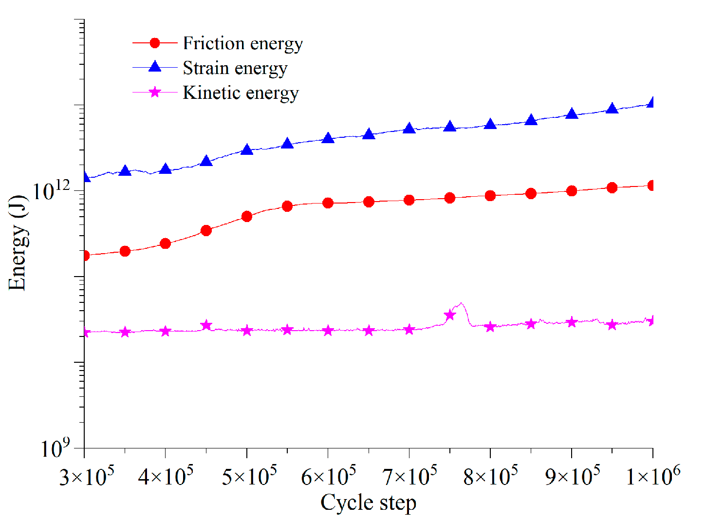
5. Evolutionary Characteristics of Energy Field

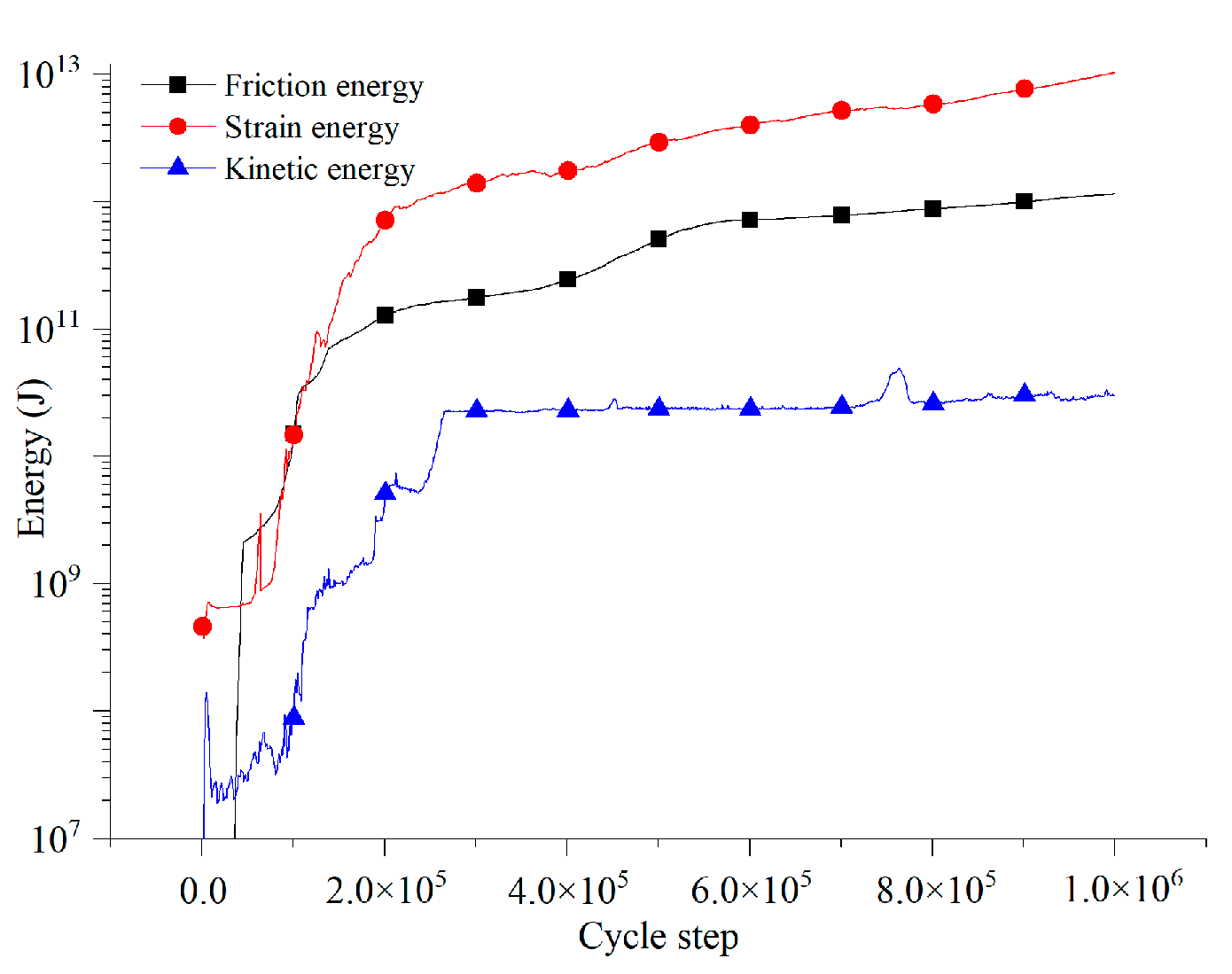
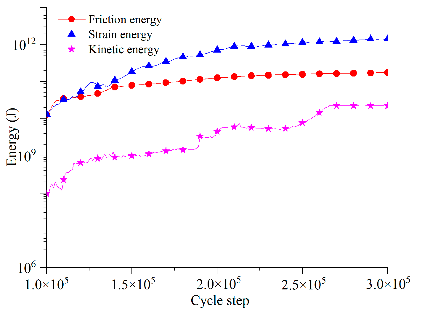
5.1. Energy Evolution Characteristics in Whole Toppling Process

Energy dissipation in PFC obeys the following rules:
Total energy deposited in particle:
W ( i ) = 1 4 ( M ( i ) + + M ( i ) ) V ( i ) 2
Lost energy in every cycle for friction:
Δ W ( i ) = 2 [ 1 2 ( M ( i ) + M ( i ) ) V ( i ) 2 ]
  • V ( i ) : Particle velocity
  • M ( i ) : Particle mass
The ratio of lost energy in every cycle to maximum energy saved in particle is called the “ratio of the lost”, which can be expressed as follows:
Δ W ( i ) W ( i ) = 4 ( M ( i ) + M ( i ) ) M ( i ) + + M ( i ) = 4 α
Critical friction coefficient D can be expressed as the ratio of the lost when the friction coefficient is small:
D = Δ W ( i ) / W ( i ) 4 π = α π
α is the friction coefficient deciding the value of the friction force. It can be set to all of the particles in the model by PFC’s built-in code, which has the following advantages: (1) friction influence is only installed at the acceleration part and there will be no wrong friction force in static state; (2) friction coefficient is dimensionless; (3) friction is independent of frequency.
The toppling deformation process is essentially a process of transformation and dissipation of energy. Under the action of the self-weight, part of the gravitational potential energy will be transformed into strain energy and the other part will be dissipated into friction energy. As strain energy is deposited in rock mass, when it exceeds the maximum value, the rock will break up and release energy, then inducing lots of cracks, as shown in Figure 16. For studying the evolutionary characteristics of the energy field in the toppling deformation process, characteristics of strain energy, friction energy, and crack propagation will be monitored in the simulation.
According to Figure 17, strain energy is the largest; the friction energy is smaller; the kinetic energy is the smallest. All of them increase with cycle steps, and the steeply increasing range is from 100,000 to 300,000 cycle steps.
The energy field can be presented by crack propagation, and the development characteristics of crack number (Figure 18) with cycle steps are similar to those of energy evolution. The similarity can be found in that the crack number also increases slowly at the beginning, from 0 to 100,000 cycle steps; it then steeply increases from 100,000 to 300,000 cycle steps, finally slowing down and becoming stable after 300,000 cycle steps.

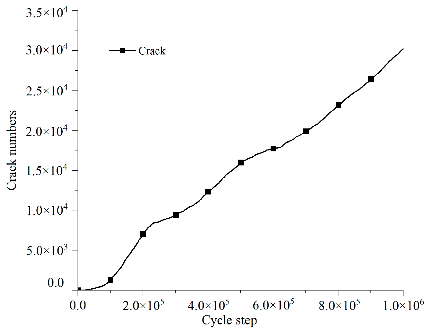
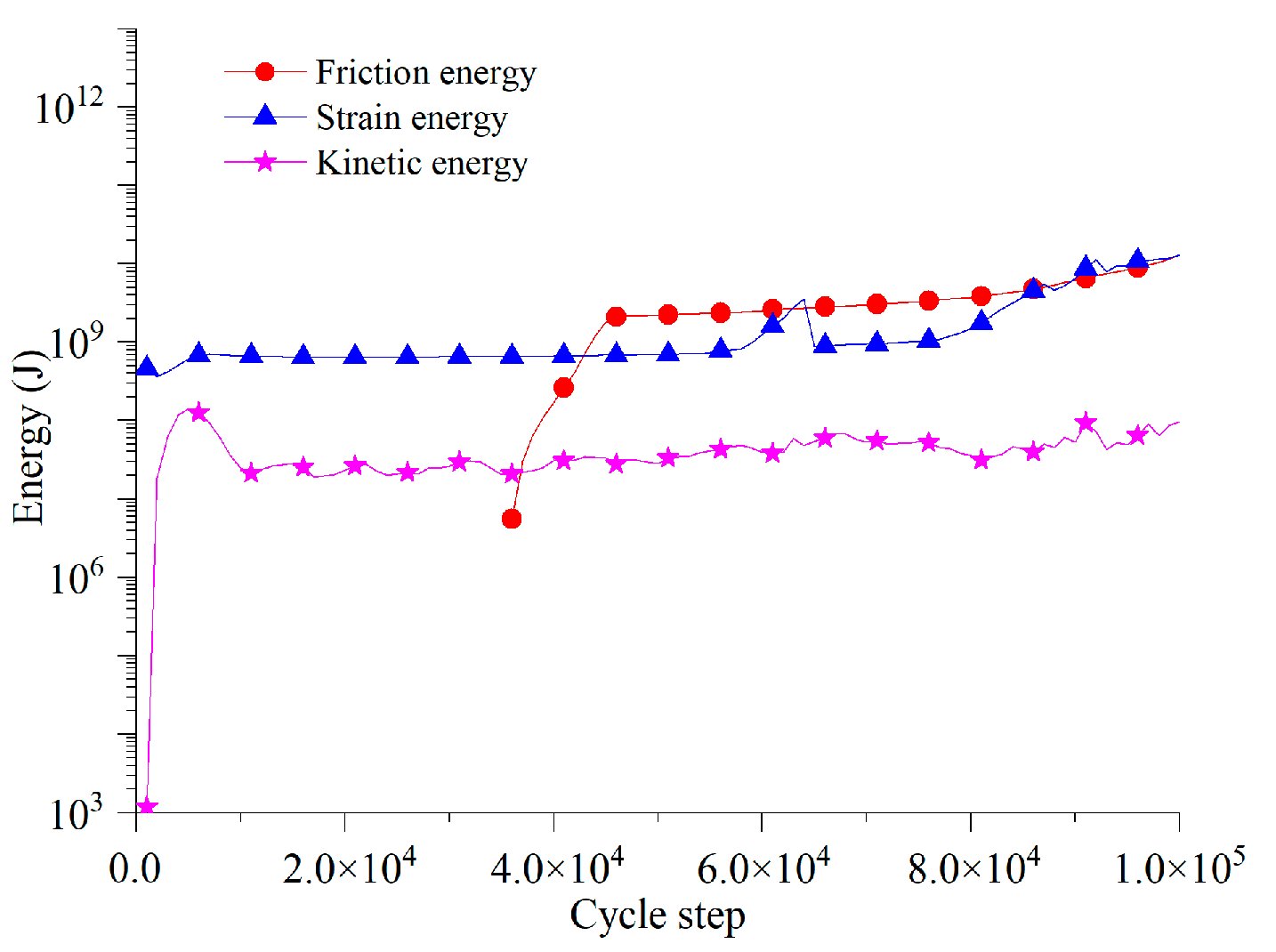
5.2. Dividing Evolution Stage of Toppling Deformation Based on Characteristics of Energy Field

Combining analysis of the evolutionary characteristics of the energy field with characteristics of crack propagation, the evolution of toppling deformation was divided into three stages: (1) shear deformation stage, (2) stage of main toppling fracture surface hole-through, and (3) stage of secondary toppling and fracture surface development.
(1) Shear deformation stage
As presented in Figure 19, toppling deformation between 0 and 100,000 cycle steps is categorized as the shear deformation stage, in which the strain energy, friction energy, and kinetic energy are small. In the later period of this stage, strain energy and friction energy have a relatively small increasing tendency, but the variation rate of kinetic energy is stable, which means that energy is accumulating and the rate of the deformation of the bank slope is slow at this stage.
In this stage, deformation of the bank slope consists of mainly shearing deformation in the slope toe, as shown in Figure 20. The toppling deformation in the middle and rear parts is weak, and there is integral deformation failure in deep strata of the slope toe due to the shearing action. At this stage, variation of the slope angle is tiny.
Figure 21 shows that shear cracks develop in a nearly horizontal direction in the slope toe, resulting in shearing fractures in the deep rock strata, weak toppling deformation in the middle and rear parts, and sporadically distributed cracks within a depth of 100 m in the bank slope.
(2) Stage of main toppling fracture surface hole-through
As shown in Figure 22, toppling deformation from 100,000 to 300,000 cycle steps is classified as the stage of main toppling fracture surface hole-through, in which all three types of energy present an increasing tendency, which is especially obvious for strain energy and kinetic energy.
At the stage of main toppling fracture surface hole-through, the bank slope deformation is mainly shown as further expansion of shearing failure in the slope toe and toppling deformation in the middle and rear parts. According to Figure 23, shear deformation in the region below a height of 900 m is dominant where variation of the slope angle is small, and secondary shearing and fracture surface are found at a depth of 80 m; toppling deformation along the fracture surface occurs in the region above the height of 900 m, and the deflection angle in rock strata is around 10 to 20 degrees.
Deformation characteristics of the actual bank slope in the later period of monitoring are similar to those of the numerical model at this stage, shearing deformation being dominant in the frontal strata and toppling deformation being dominant in the rear part. However, main toppling and fracture surface in this stage are not completely visible, there being no slip surface in the area with a height of around 900 m. It is easy to see that the fracture mentioned in Figure 11 is rather obvious at this stage, meaning that the accuracy of the numerical model is further proven.
At this stage, shear cracks in the slope toe expand to deeper areas; tensile cracks in the bank slope are densely distributed in the region with a depth of 100 m (Figure 24). Propagation of these tensile cracks induces main toppling and fracture surface.
(3) Stage of secondary toppling and fracture surface development
The period after 300,000 cycle steps is classified as the stage of secondary toppling and fracture surface development, as shown in Figure 25, in which strain energy and friction energy increase at a stable velocity, with kinetic energy almost keeping constant.
At the stage of secondary toppling and fracture development, bank slope deformation is mainly presented as secondary shearing and fracture surface and dense development of secondary toppling and fracture surface. Marked in Figure 26, there is further shear failure with rock mass in the shallow layer and the development of secondary shearing and fracture surface in the region below the height of 900 m; there is further toppling failure with rock mass in the shallow layer, development of secondary toppling and fracture surface, and further dip angle deflection of strata along secondary toppling and fracture surface in the region with a height above 900 m.
At the stage of secondary toppling and fracture surface development, there is more dense development of cracks in the region above the main toppling and fracture surface, inducing plenty of secondary toppling and fracture surfaces (Figure 27).

6. Conclusions

1. Evolutionary characteristics of displacement field
Analysis of the evolutionary characteristics of the displacement field showed that horizontal displacement is dominant on the surface, and there is an uplift in the front part of the bank slope for shearing deformation. The influence of vertical displacement in the middle and rear regions is stronger than that in the front region and becomes stronger in the middle region in the later period of the evolutionary process.
2. Evolutionary characteristics of energy field
Analysis of the evolutionary characteristics of the energy field showed that all three types of energy have an increasing trend, and the period with 100,000 to 300,000 cycle steps is the most steeply increasing period. The strain energy is the largest, friction energy second, and kinetic energy is smallest. It also showed that the evolutionary characteristic of cracks is the same as that of energy in that crack number also increases slowly in the early period, steeply in the middle period, then becomes slow and stable in the later period.
3. According to the evolutionary characteristics of the energy field, the evolution stages of toppling deformation was divided into (1) shear deformation stage, (2) stage of main toppling fracture surface hole-through, and (3) stage of secondary toppling and fracture surface development.
In the shear deformation stage, shear deformation in the slope toe is dominant at this stage, in which friction energy, strain energy, and kinetic energy are all relatively small. It is an energy accumulating stage, and cracks are loosely distributed in the bank slope body within a depth of 100 m. At the stage of main toppling fracture surface hole-through, all three types of energy present an increasing trend, which is especially obvious for strain energy and kinetic energy. Shear cracks expand further to deeper places; at the same time, tensile cracks are densely distributed in the region within a 100 m deep. At the stage of secondary toppling and fracture surface development, deformation consists of mainly secondary shearing of the fracture surface and the development of secondary toppling and fracture surface, in which strain energy and friction energy increase uniformly and kinetic energy remains constant.

Author Contributions

Data curation, L.X.; formal analysis, L.X.; funding acquisition, L.X.; investigation, L.X.; methodology, L.X.; project administration, L.X.; resources, L.X.; software, L.X.; supervision, L.X. and Q.Z.; validation, L.X. and Q.Z.; visualization, Q.Z.; writing—original draft, Q.Z.; writing—review and editing, Q.Z., Y.Q., J.W. and J.Q. All authors have read and agreed to the published version of the manuscript.

Funding

This research was funded by the National Natural Science Foundation of China (grant number: 51908482) and the Scientific Research Program of the Higher Education Institution of Xinjiang (grant number: XJEDU2018Y008).

Conflicts of Interest

The authors declare no conflict of interest.

References

  1. Huang, R. Large-scale landslides and their sliding mechanisms in China since the 20th century. Yanshilixue Yu Gongcheng Xuebao/Chin. J. Rock Mech. Eng. 2007, 26, 433–454. [Google Scholar]
  2. Mathis, J.I. Toppling failure—A proposed analytic solution. CIM Bull. 2004, 97, 60–61. [Google Scholar]
  3. Tu, X.; Dai, F.; Lu, X.; Zhong, H. Toppling and stabilization of the intake slope for the Fengtan Hydropower Station enlargement project, Mid-South China. Eng. Geol. 2007, 91, 152–167. [Google Scholar] [CrossRef]
  4. Alejano, L.R.; Gómez-Márquez, I.; Martínez-Alegría, R. Analysis of a complex toppling-circular slope failure. Eng. Geol. 2010, 114, 93–104. [Google Scholar] [CrossRef]
  5. Liu, C.H.; Jaksa, M.B.; Meyers, A.G. Toppling mechanisms of rock slopes considering stabilization from the underlying rock mass. Int. J. Rock Mech. Min. Sci. 2010, 47, 348–354. [Google Scholar] [CrossRef]
  6. Cruden, D.; Hu, X.-Q.; Lu, Z. Rock topples in the highway cut west of Clairvaux Creek, Jasper, Alberta. Can. Geotech. J. 2011, 30, 1016–1023. [Google Scholar] [CrossRef]
  7. Bi, J.; Luo, X.; Zhang, H.; Shen, H. Stability analysis of complex rock slopes reinforced with prestressed anchor cables and anti-shear cavities. Bull. Eng. Geol. Environ. 2019, 78, 2027–2039. [Google Scholar] [CrossRef]
  8. Zhang, G.; Zhao, Y.; Peng, X. Simulation of Toppling Failure of Rock Slope by Numerical Manifold Method. Int. J. Comput. Methods 2010, 7, 167–189. [Google Scholar] [CrossRef]
  9. Zheng, Y.; Chen, C.; Liu, T.; Zhang, H.; Xia, K.; Liu, F. Study on the mechanisms of flexural toppling failure in anti-inclined rock slopes using numerical and limit equilibrium models. Eng. Geol. 2018, 237, 116–128. [Google Scholar] [CrossRef]
  10. Cai, J.-C.; Ju, N.-P.; Huang, R.-Q.; Zheng, D.; Zhao, W.-H.; Li, L.-Q.; Huang, J. Mechanism of toppling and deformation in hard rock slope: A case of bank slope of Hydropower Station, Qinghai Province, China. J. Mt. Sci. 2019, 16, 924–934. [Google Scholar] [CrossRef]
  11. Tao, Z.; Geng, Q.; Zhu, C.; He, M.; Cai, H.; Pang, S.; Meng, X. The mechanical mechanisms of large-scale toppling failure for counter-inclined rock slopes. J. Geophys. Eng. 2019, 16, 541–558. [Google Scholar] [CrossRef] [Green Version]
  12. Zhou, X.; Chen, J. Extended finite element simulation of step-path brittle failure in rock slopes with non-persistent en-echelon joints. Eng. Geol. 2019, 250, 65–88. [Google Scholar] [CrossRef]
  13. Zheng, Y.; Chen, C.; Liu, T.; Xia, K.; Liu, X. Stability analysis of rock slopes against sliding or flexural-toppling failure. Bull. Eng. Geol. Environ. 2018, 77, 1383–1403. [Google Scholar] [CrossRef]
  14. Eberhardt, E. Twenty-ninth Canadian Geotechnical Colloquium: The role of advanced numerical methods and geotechnical field measurements in understanding complex deep-seated rock slope failure mechanisms. Can. Geotech. J. 2008, 45, 484–510. [Google Scholar] [CrossRef]
  15. Adhikary, D.P.; Dyskin, A.V.; Jewell, R.J.; Stewart, D.P.J.R.M.; Engineering, R. A study of the mechanism of flexural toppling failure of rock slopes. Rock Mech. Rock Eng. 1997, 30, 75–93. [Google Scholar] [CrossRef]
  16. Brideau, M.-A.; Stead, D. Controls on Block Toppling Using a Three-Dimensional Distinct Element Approach. Rock Mech. Rock Eng. 2010, 43, 241–260. [Google Scholar] [CrossRef]
  17. Wu, J.; Ohnishi, Y.; Shi, G.; Nishiyama, S. Three dimensional discontinuous deformation analysis (3d dda) and its application to the rock slope toppling. Chin. J. Rock Mech. Eng. 2003, 22, 937–942. [Google Scholar]
  18. Gschwind, S.; Loew, S.; Wolter, A. Multi-stage structural and kinematic analysis of a retrogressive rock slope instability complex (Preonzo, Switzerland). Eng. Geol. 2019, 252, 27–42. [Google Scholar] [CrossRef]
  19. Alejano, L.R.; Veiga, M.; Pérez-Rey, I.; Castro-Filgueira, U.; Arzúa, J.; Castro-Caicedo, Á.J. Analysis of a complex slope failure in a granodiorite quarry bench. Bull. Eng. Geol. Environ. 2017, 78, 1209–1224. [Google Scholar] [CrossRef]
  20. Xu, N.; Wu, J.; Dai, F.; Fan, Y.; Li, T.; Li, B. Comprehensive evaluation of the stability of the left-bank slope at the Baihetan hydropower station in southwest China. Bull. Eng. Geol. Environ. 2017, 77, 1567–1588. [Google Scholar] [CrossRef]
  21. Wu, C.S.; Feng, Z.Y.; Yang, H.; Zhang, D.M.; Wang, Y. Evolution Mechanism of Rock Slope Slide Based on Fiber Optic Sensors. J. Nanoelectron. Optoelectron. 2017, 12, 913–919. [Google Scholar] [CrossRef]
  22. Zhang, Z.; Liu, G.; Wu, S.; Tang, H.; Wang, T.; Li, G.; Liang, C. Rock slope deformation mechanism in the Cihaxia Hydropower Station, Northwest China. Bull. Eng. Geol. Environ. 2015, 74, 943–958. [Google Scholar] [CrossRef]
  23. Li, Z.; Wang, J.A.; Li, L.; Wang, L.; Liang, R.Y. A case study integrating numerical simulation and GB-InSAR monitoring to analyze flexural toppling of an anti-dip slope in Fushun open pit. Eng. Geol. 2015, 197, 20–32. [Google Scholar] [CrossRef] [Green Version]
  24. Yoon, J. Application of experimental design and optimization to PFC model calibration in uniaxial compression simulation. Int. J. Rock Mech. Min. Sci. 2007, 44, 871–889. [Google Scholar] [CrossRef]
  25. Potyondy, D.O.; Cundall, P.A. A bonded-particle model for rock. Int. J. Rock Mech. Min. Sci. 2004, 41, 1329–1364. [Google Scholar] [CrossRef]
  26. Carranza-Torres, C.; Corkum, B.; Hoek, E.; Carranza-Torres, C. Hoek-Brown Failure Criterion—2002. Proc. NARMS-Tac. 2002, 1, 267–273. [Google Scholar]
  27. Cai, J.-S.; Yan, E.C.; Wang, Z.-Q.; Yang, J.-G.; Tang, R.-X. Study of cantilever beam limit equilibrium model of anti-dip layered rock slopes. Yantu Lixue/Rock Soil Mech. 2014, 35, 15–28. [Google Scholar]
Figure 1. Geographic location of the Xiaodongcao bank slope.
Sustainability 12 07544 g001
Figure 2. Details of exposed rock and soil: (a) plan of the exposed rock and soil mass on the bank slope; (b) profile of the exposed rock and soil on the bank slope.
Sustainability 12 07544 g002
Figure 3. Three-dimensional surface deformation zoning map of bank slope.
Sustainability 12 07544 g003
Figure 4. Layout of the monitoring system of the surface displacement.
Sustainability 12 07544 g004
Figure 5. Monitoring displacement of 2-2′ longitudinal profile (middle line) of the bank slope.
Sustainability 12 07544 g005
Figure 6. Numerical rock tests: rock tests (left), stress–strain curve (right).
Sustainability 12 07544 g006
Figure 7. Numerical simulation model of bank slope.
Sustainability 12 07544 g007
Figure 8. Arrangement of monitoring points for numerical simulation of bank slope.
Sustainability 12 07544 g008
Figure 9. Simulated horizontal displacement curve from monitoring point C.
Sustainability 12 07544 g009
Figure 10. Simulated vertical displacement curve from monitoring point C.
Sustainability 12 07544 g010
Figure 11. Deformation and failure characteristics of bank slope: (a) deformation and failure characteristics in numerical model; (b) actual profile of exposed rock and soil.
Sustainability 12 07544 g011
Figure 12. Comparison of bank slope toppling deformation before and after evolution.
Sustainability 12 07544 g012
Figure 13. Evolutionary characteristics of surficial horizontal displacement field.
Sustainability 12 07544 g013
Figure 14. Evolutionary characteristics of surficial vertical displacement field.
Sustainability 12 07544 g014
Figure 15. Evolutionary characteristics of the ratio of vertical displacement to horizontal displacement on surface.
Sustainability 12 07544 g015
Figure 16. Graph of crack propagation by toppling deformation.
Sustainability 12 07544 g016
Figure 17. Characteristic curve of the energy field in toppling deformation.
Sustainability 12 07544 g017
Figure 18. Development and evolutionary characteristic curve of bank slope cracks.
Sustainability 12 07544 g018
Figure 19. Evolutionary characteristics of the energy field at the shear deformation stage.
Sustainability 12 07544 g019
Figure 20. Deformation characteristics at shear deformation stage.
Sustainability 12 07544 g020
Figure 21. Diagram of crack distribution at shear deformation stage.
Sustainability 12 07544 g021
Figure 22. Evolutionary characteristics of the energy field at the stage of main toppling fracture surface hole-through.
Sustainability 12 07544 g022
Figure 23. Deformation characteristics at stage of main toppling fracture surface hole-through.
Sustainability 12 07544 g023
Figure 24. Diagram of crack distribution at stage of main toppling fracture surface hole-through.
Sustainability 12 07544 g024
Figure 25. Evolutionary characteristics of energy field at the stage of secondary toppling and fracture surface development.
Sustainability 12 07544 g025
Figure 26. Deformation characteristics of bank slope at stage of secondary toppling and fracture surface development.
Sustainability 12 07544 g026
Figure 27. Diagram of crack distribution at stage of secondary toppling and fracture surface development.
Sustainability 12 07544 g027
Table 1. Each partition’s characteristics of slope surface deformation failure.
Zone NumberDeformation ExtentPositionDistribution Height (m)Area
(104 m2)
Material StructureDeformation Characteristics
IFailureTrailing edge1070–11804.9Residual slope, mainly silty clayCracks, house deformation
IIWeak deformation Local failureDitch four610–8800.2Landslide layer, block stoneRock mass collapse
IIIFailureRight side of ditch four610–7551.2Strongly weathered rock massRock and soil slide
IVWeak deformationLeft side of ditch two650–7200.5Landslide layer, gravelly soilRock and soil slide
VFailureRight side of ditch four610–7552.4Landslide layer, gravelly soilRock and soil slide
VIFailureDitch one610–11601.1Landslide layer, block stoneRock mass collapse
VIIWeak deformationThe whole bank slope526–118062.8Dolomite limestone, mud limestoneFlexural toppling
Table 2. Macro parameters of rock mass.
Formation LithologyYoung′ s ModulusPoisson’s RatioUniaxial Compressive StrengthTension StrengthCohesionInternal Friction Angle
E/GPaν σ c / MPa σ t / MPa c/MPaφ
T1j5.5400.24518.15−0.1861.84329.74
T1d2.2540.29710.16−0.0371.00320.33
Table 3. Microscopic parameters of rock mass.
ItemsValues
Formation LithologyT1jT1d
Minimum particle size (m)0.50.5
Maximum particle size (m)1.01.0
Particle contact module (GPa)2.51.2
Ratio of contact module1.82.2
Particle friction coefficient0.20.1
Parallel bond module (GPa)2.51.2
Ratio of parallel bond module1.82.2
Normal strength (MPa)10.06.0
Tangential strength (MPa)5.03.0
Friction angle (°)10.05.0

