1. Introduction
There is a trend towards greater building transparency, strengthening the interaction between outdoor and internal spaces, and glass is the main type of transparent enclosure material used in practical engineering. However, there are many circumstances where glass is not a viable option because of the building geometry. Hence, a membrane structure that is commonly built with new materials such as ethylene tetrafluoroethylene (ETFE) is applied as an alternative to glass via the flexibility of the ETFE membrane for the curvature of the building [
1,
2]. Numerous large-scale public buildings, such as stadiums, are constructed with ETFE air pillows as the roofs or building envelopes [
3]. Examples include the Allianz Arena in Germany as a soccer stadium (2006), the National Aquatics Center in China as an Olympic facility (2008), and the Stadium of Dalian Sports Center in China as a venue for 2013 China National Games (2011). The National Aquatics Center of China is the largest building in the world utilizing an ETFE air pillow structure as its building envelope.
A double translucent pillowed ETFE structure integrated with a cavity is employed in the National Aquatics Center. The light-transmittance of the ETFE is over 90%, and it is 100% recyclable and requires minimal energy for production and installation [
3]. The transparent or translucent ETFE air pillows provide good lighting, but also bring problems such as reduced indoor comfort and high cooling energy consumption in the summer.
As the construction cost of the Olympic Games infrastructure becomes higher and higher, sustainability has become an important part of the contemporary Olympic Games. The International Olympic Committee’s “Olympic 2020 Agenda” encourages the maximum use of the city’s existing venues, temporary venues, and detachable venues to host the Olympic Games [
4]. Guided by the concept of sustainable operation and maintenance, the National Aquatics Center “Water Cube” will host men’s and women’s curling and wheelchair curling competitions during the 2022 Winter Olympics and Paralympic Games. Thus, the lighting advantage of the ETFE structure has become a disadvantage in the Winter Olympics, while a large amount of solar radiation increases the load of the ice-making system.
In recent years, there has been relatively more research on the thermal performance of transparent building envelopes. Laouadi and others simulated the thermal process and energy status of the building’s lighting roof under cold climate conditions, which provided the research for the establishment of the roof heat transfer model [
5]. Double skin facades (DSFs) are used to better the thermal energy performance of building facades with high glazing fractions [
6,
7,
8]. DSF is the building envelope formed by two layers (internal layer and external layer), separated by a ventilated air cavity [
9], and its performance is identified as influenced by the following factors: the depth and height of the cavity, the shading device within the cavity, and the solar irradiance [
10,
11]. Jefferson discussed the impact of reflectivity and emissivity on the thermal performance of light metal roofs [
12], and JP Brito Filho conducted a comparative analysis of the thermal performance of different coatings and vapor barriers on the large metal ceiling [
13], providing guidance for the selection of sheltering schemes.
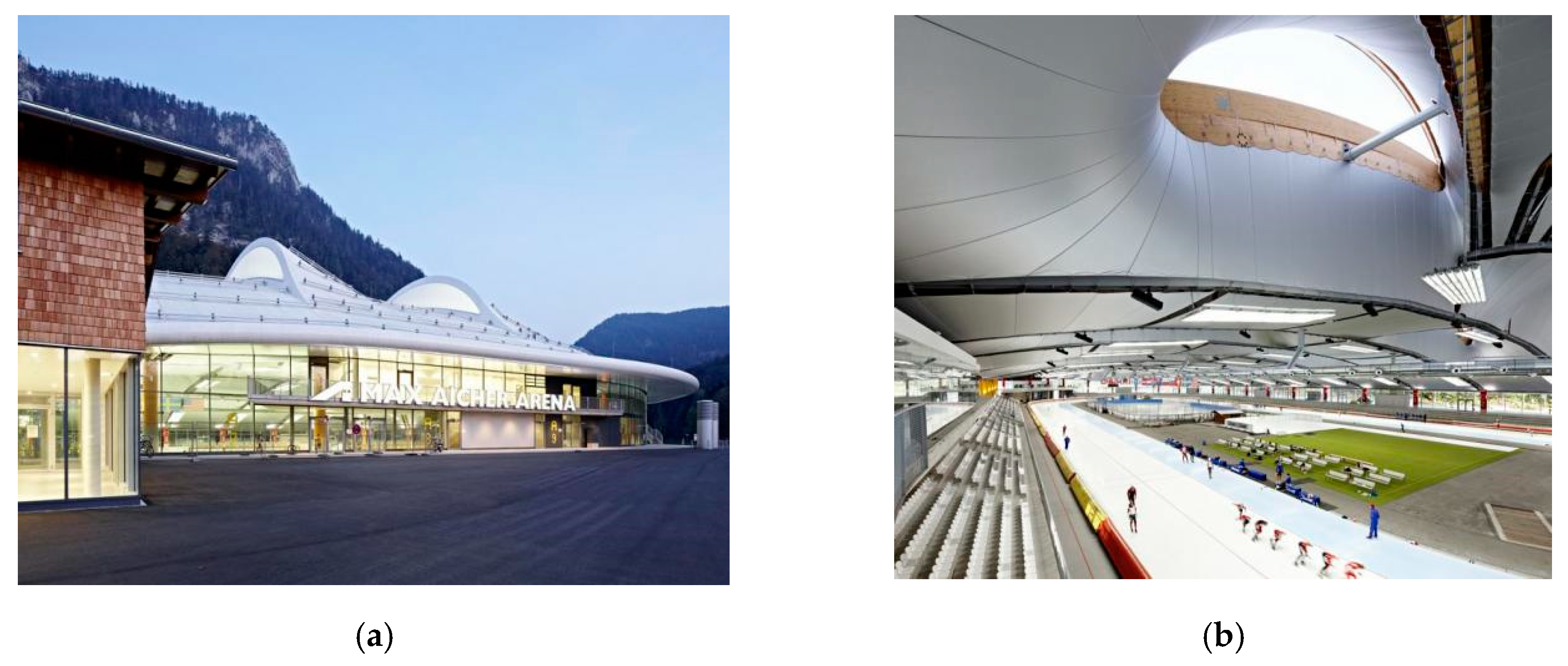
As for ice stadiums, “
Swimming Pools and Ice Rinks” pointed out that the indoor ice rink ceiling can be equipped with high reflectivity hanging film to reduce the cooling load on the ice surface. For example, Cardiff’s high-reflection dispersion ceiling is used in the National Ice Rink in Wales [
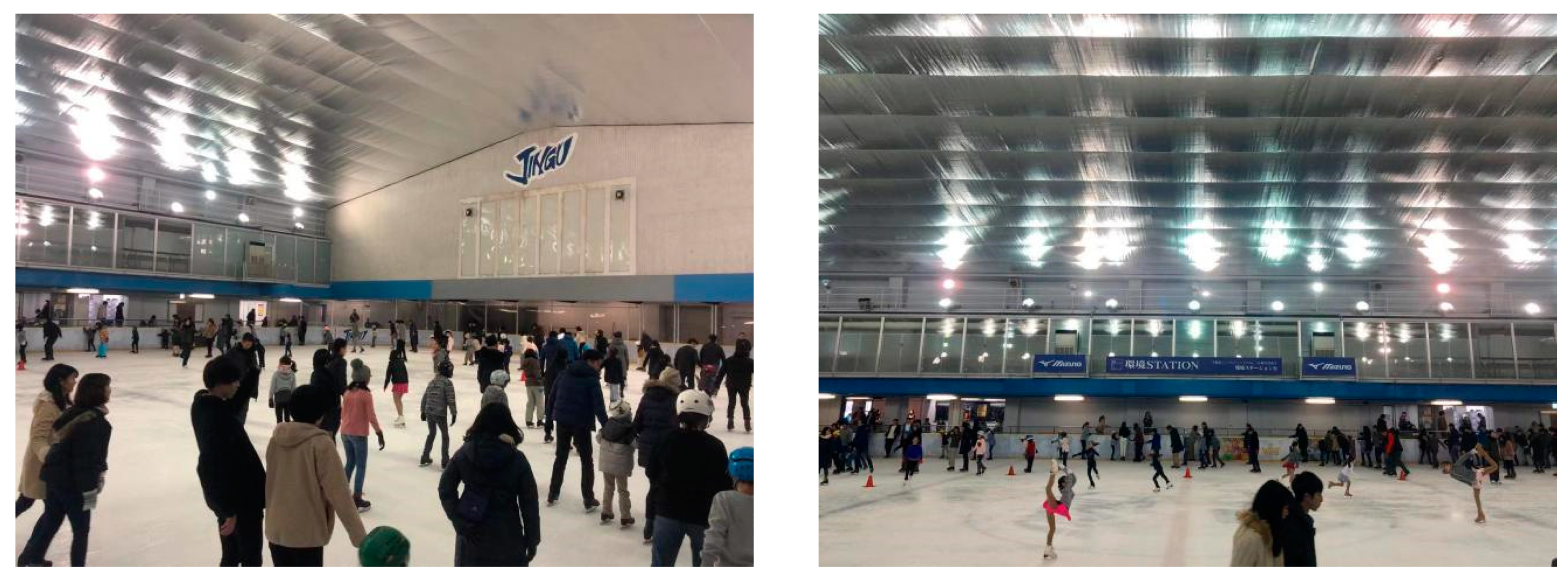
14]. At the Germany Inzell Speed Skating Stadium—under which’s roof, low-emission thin film structural material ceiling is used—the membrane cloth is spread between the steel and wooden truss to reflect the cold radiation of the ice surface onto the track, thereby maintaining the stable low temperature of the ice surface. At the same time, the translucent film material also scatters natural light into the room through 17 north-facing skylights, which meets the requirement that ice stadiums should avoid direct natural light (
Figure 1). The ceiling of Meiji Jingu Waiyuan Ice Rink in Tokyo, Japan uses low-emission materials to reduce the heat load on the ice surface and prevent the ice surface from melting (
Figure 2).
However, there is still limited information on the actual thermal and humidity behavior of the double ETFE air pillow structure. Furthermore, there are few buildings that actually use double ETFE air pillow structure, not to mention ice stadiums.
For venues that use translucent roofs, such as the National Aquatics Center, using a combined ceiling structure with a shielding material that can be flexibly installed and removed between the roof and the ceiling are potential energy-saving transformation measures. From the perspective of actual construction, this paper proposes a measure for energy-saving optimization of the roof enclosure structure of the ice stadium. By laying a PVC film-based black coated fabric material in the cavity of the ETFE air pillow to block the transmission of sunlight, we hypothesize it will reduce the indoor temperature refrigeration load on ice and avoid condensation on the ceiling. On-site measurement and simulation, analysis, and research on its thermal performance will provide theoretical support for the expansion of the venue’s post-match use function, the realization of the conversion between summer venue and winter venue, and the formation of the “Double Olympic Games” exemplary sustainable operational heritage.
2. Materials and Methods
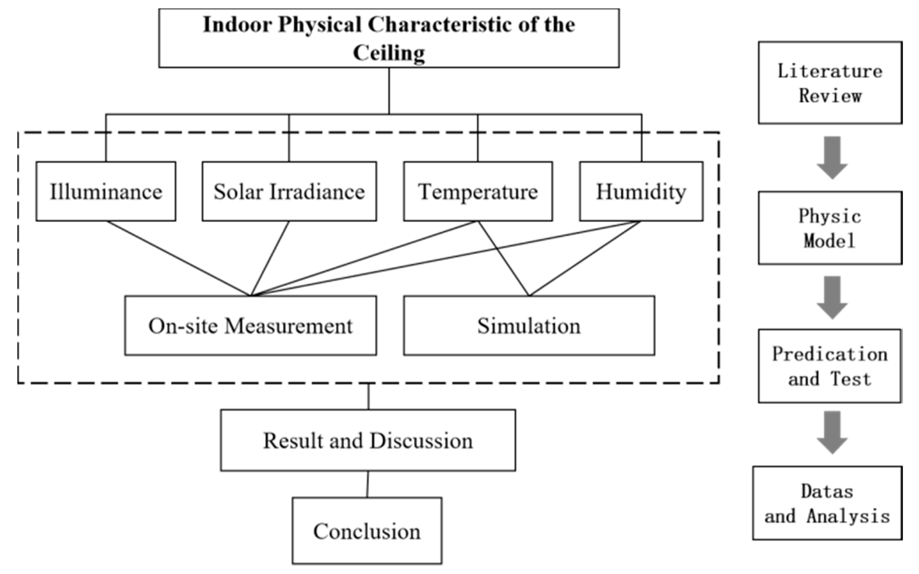
2.1. Research Ideas
The research was carried out as the flowchart (
Figure 3).
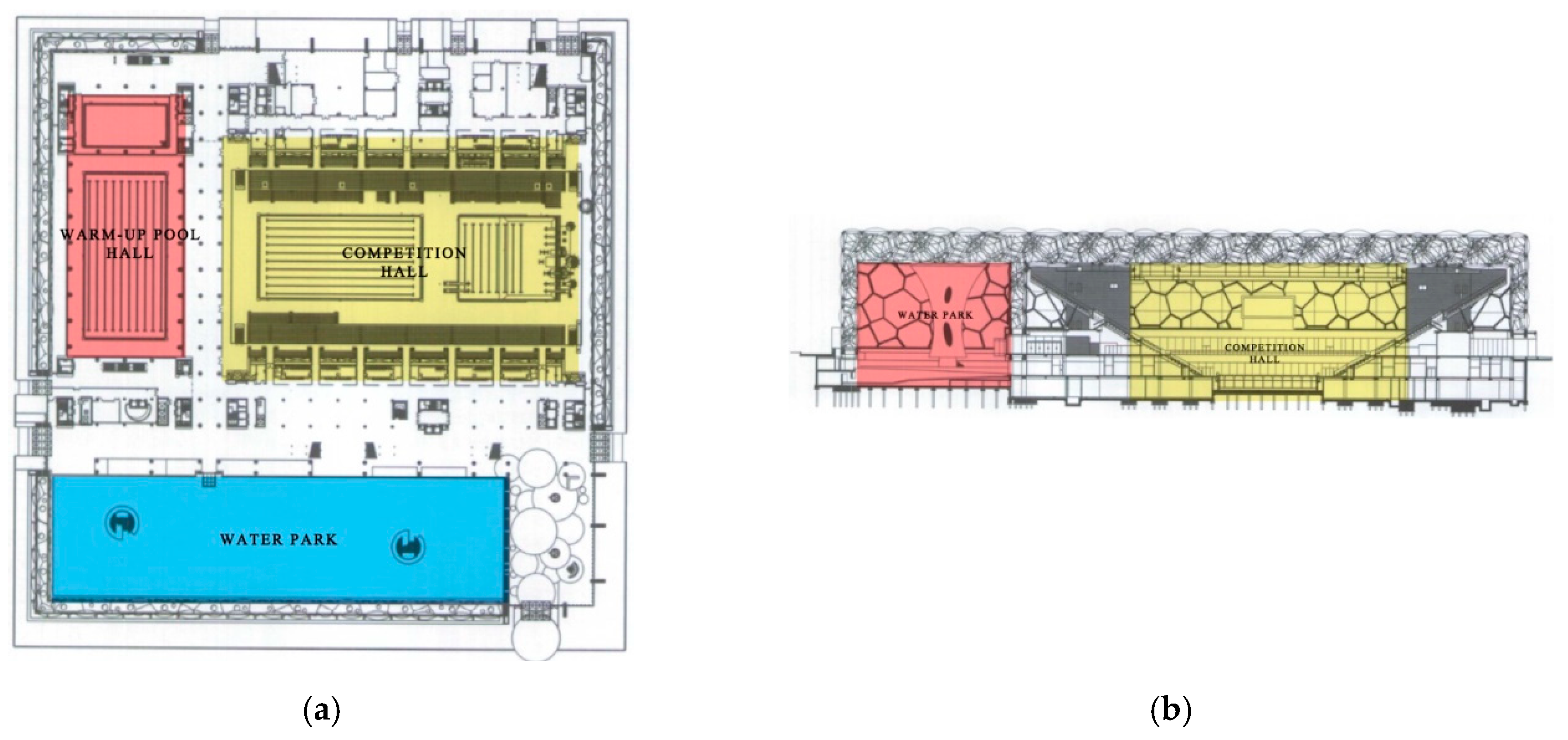
2.2. Description of the Building and the Demands for the Olympics
The plan layout of the National Aquatics Center consists of three basic spaces: a competition hall of about 130 m × 130 m, including swimming competition pool (50 m × 25 m × 3 m), diving competition pool (30 m × 25 m × 4.5–6 m), and 17,000 standard seats; a water park located on the south side; a warm-up pool hall (50 m × 25 m × 2 m) between the basement and the first floor, above which is a multifunctional indoor sports field, which can be set up according to needs into 3 tennis courts, 2 basketball courts, or 1 ice rink (
Figure 4). During the 2022 Winter Olympics, the National Swimming Center “Ice Cube” will add on-ice functions on the basis of retaining the “Water Cube” water function. Our research was carried out in the competition hall.
According to Sports Architecture Design Manual [
16], Sports Building Design Code [
17], Ice and Snow Blue Book series [
18], and National Building Standard Design Atlas [
19], etc., the following requirements were set for the ice surface of the artificial ice rink: the ice surface should be smooth and flat without any obstacles. For curling, the thickness of the ice surface is 40–50 mm, and the temperature of the ice surface ranges from −5 to −6.5 °C. In order to avoid partial melting of the ice surface and damage to its flatness, hardness, and other properties, the ice surface should be protected from direct light [
20]. The American Society of Heating, Refrigeration and Air-Conditioning Engineers (ASHRAE) recommended an ice thickness of 25–32 mm in 2014, and in the International Ice Hockey Federation’s ice rink guide, the recommended ice thickness of 25–30 mm is basically the same [
21].
2.3. Source of Heat Load on Ice Rink
“
ASHRAE handbook-HVAC applications (SI)” pointed out the source of the heat load of indoor ice rink [
22], as shown in
Table 1. Among them, the heat radiated from the ceiling accounts for 28% of the total heat of the ice rink, ranking first, but the heat radiated from the ceiling has the greatest reduction potential, up to 90%. Since heat radiation is closely related to the indoor thermal and humidity environment, reducing the heat radiation of the ceiling enclosure structure is a key factor to reduce the indoor temperature of the ice rink and maintain the stability of its indoor environment.
2.4. Analysis of Heat Transfer Performance of Ceiling System and Predictions
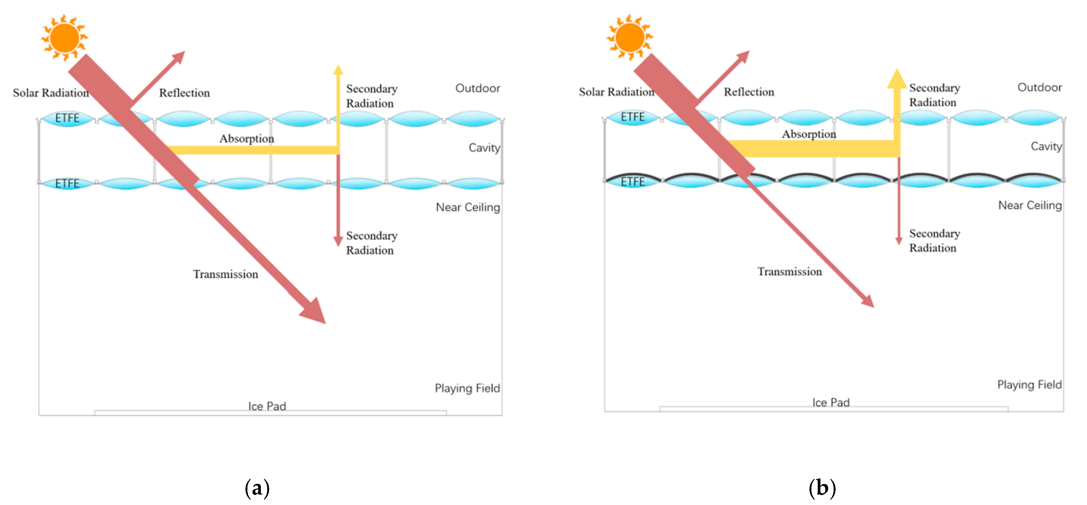
In order to clarify the influence of the ceiling structure on the indoor physical environment, the heat transfer physical model of the ceiling structure in the “Water Cube” was analyzed, as shown in
Figure 5. The forms of heat transfer involved in the ceiling include radiation, convection, and heat conduction. Since the air pillow is a double-layer or multi-layer film structure filled with air inside, its thermal conductivity is poor, and its heat transfer to the room is small. The heat transfer from the steel frame to the room belongs to heat conduction. Since the area of the steel frame is very small, the amount of heat transferred to the room is very small. The solar radiant heat energy enters the hall through the ceiling membrane structure, which belongs to radiant heat exchange. The sunlight directly illuminates the ice surface, resulting in huge instantaneous heat gain on the ice surface. The shielding material has a significant attenuation effect on the radiation of sunlight, so the transformation of the ceiling has obvious potential to stabilize and improve the indoor environment.
Through the analysis of the physical model, we speculate that the setting of shielding materials has the following effects:
- (1)
Laying shielding materials can effectively block the solar radiation reaching the ice surface, reduce the heat gain of the venue, and thus reduce the temperature;
- (2)
The ceiling system intercepts solar radiation to form a local high-temperature field, thus may increase the temperature of the cavity; and
- (3)
The shielding material can effectively absorb solar energy and convert it into heat to distribute on the upper and lower surfaces of the air pillow, increase the surface temperature of the air pillow, and prevent the water vapor in the venue from reaching the condensate formed above the venue due to the low temperature.
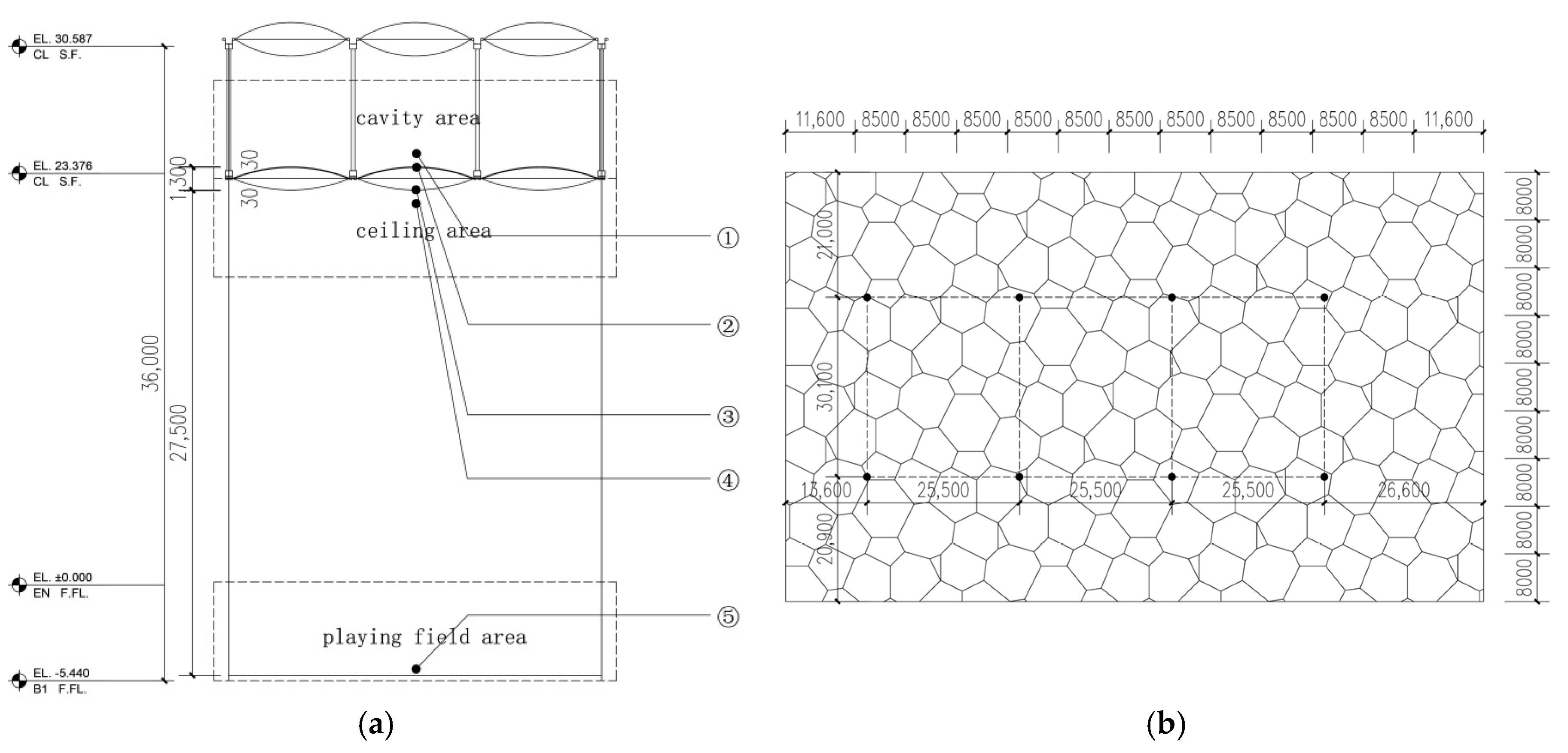
2.5. On-Site Test
In order to prove the performance and feasibility of the ceiling shading scheme proposed in this paper, a PVC film-based black-coated fabric material was laid in the ceiling cavity of the National Swimming Center in Beijing, and performance tests were carried out. Vertically, the test sites were in five sensors: the playing field, the internal ceiling, and the cavity with three different elevation areas, as shown in
Figure 6a, and the position and contents of the measuring points are shown in
Table 2. Horizontally, considering the shape, size, and the shielding effect of the complex steel structure, these air pillows were classified, and eight measurement points were evenly arranged in each vertical sensor. Then, the average value of the layer was calculated by measuring the value of eight points. The plan layout of measuring points is shown in
Figure 6b.
Considering the meteorological parameters during the Winter Olympic Games, during the winter ice rink operation period, we chose sunny days without fog and haze for the experiment. Considering the influence of the solar altitude angle within a day, the data is measured every 30 min from 9:00 to 17:00 from 7 to 9 January.
On-site test data in this study include solar irradiance, illuminance, air temperature, humidity in the cavity area, and upper surface temperature of the lower air pillow in the cavity area; solar irradiance, illuminance, air temperature, and humidity in the internal ceiling area; and the temperature of the lower surface of the air pillow. In order to collect the values of the above test parameters, the selected measuring instruments are shown in
Table 3.
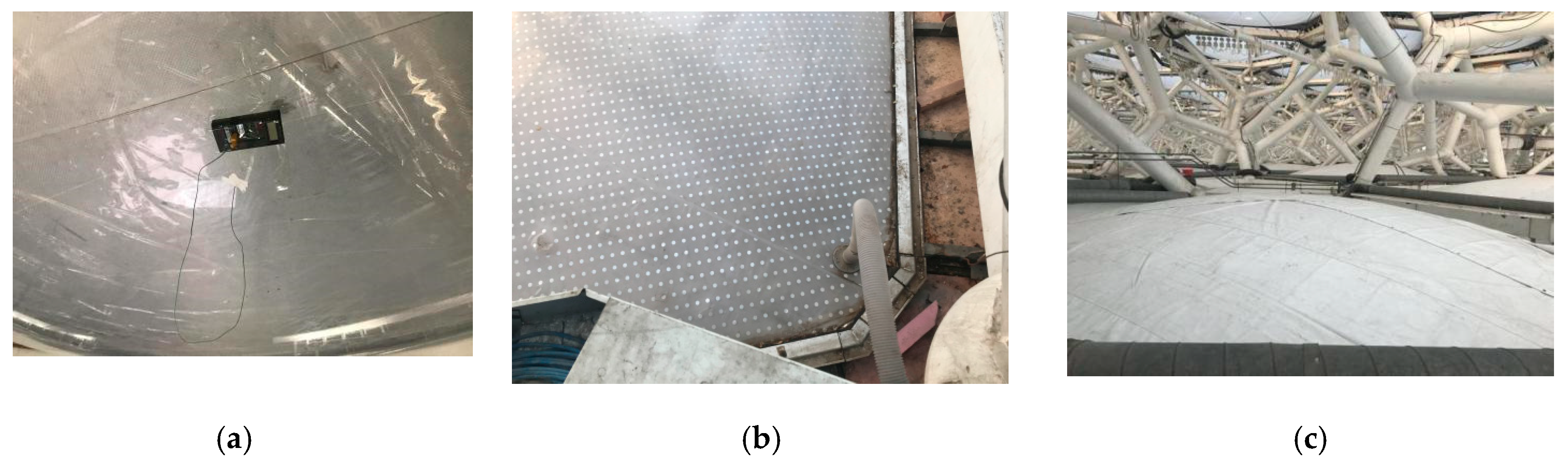
Figure 7 partially shows the on-site test.
2.6. Simulation
According to the physical characteristics of the water cube, SketchUp (v17.0.18899), Openstudio (v2.7.0), and Energyplus (v2.13) were used for simulation, and the indoor temperature and humidity were simulated. The aim was to study the effect on temperature and humidity of the PVC coating, and to predict and optimize alternative solutions, thus, we did three sets of comparison simulations as follows.
First, we simulated the annual indoor situation before and after shielding only considering solar radiation, without ventilation and air conditioning. In order to compare with the actual situation, the coating was set on the upper surface of the lower air pillow, just the same as actual.
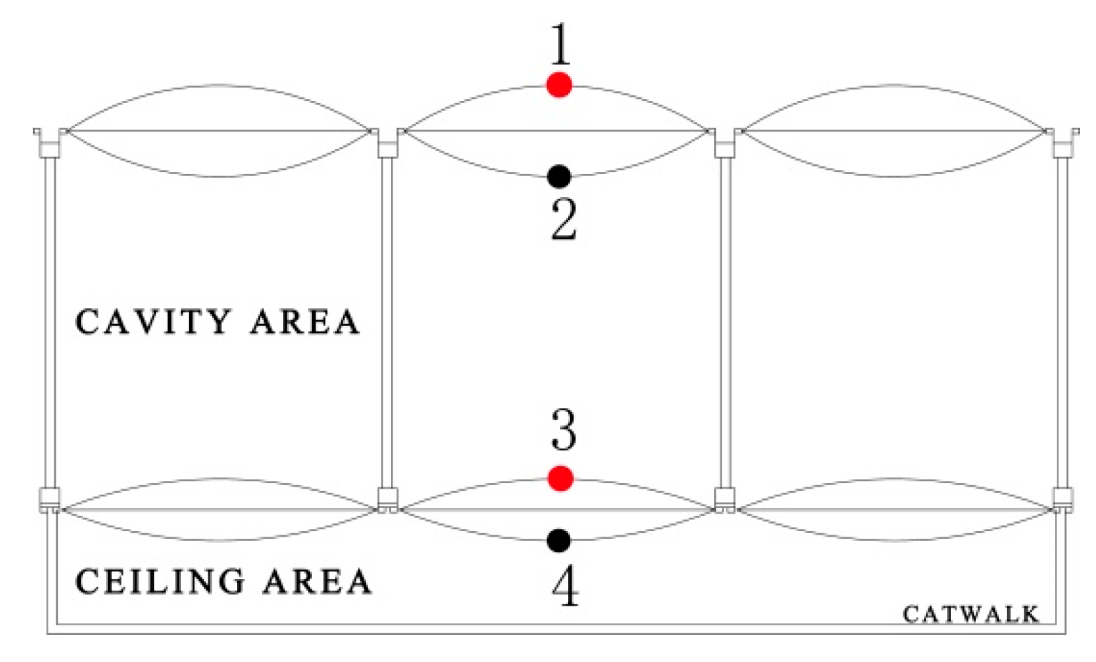
Second, a comparison simulation of PVC coating in different positions was carried out. Actually, there are four options for the placement of shielding material (
Figure 8), but considering the indoor visual effect and the difficulty of operation, it was selected to add shielding material on the roof or on the upper surface of the lower air pillow (1, 3 in
Figure 8), and we simulated the two situations separately.
Third, we adopted three different thicknesses of PVC coating to verify its optimal thickness.
As for the operation of these software, the space form of the water cube was set through SketchUp modeling firstly, and the selected simulation area was the competition hall. Second, Openstudio was used to set the thermal zones of the competition hall, and then, they were imported and adjusted in Energyplus. Finally, we set the material parameters for every ETFE air pillow on the upper and lower surfaces of the cavity, and set different areas to measure the temperature and humidity in Energyplus. The material composition of the enclosure structure and its main thermophysical properties are shown in
Table 4 and
Table 5. The measurement point is the same as the on-site measurement. The simulation results are shown in the figure below.
3. Results and Discussion
3.1. Influence of Ceiling Shielding Materials on Illumination
In the experiment, the average illuminance at different times in the cavity and near the ceiling was tested (see
Figure 6 for the measurement point). The test results are shown in
Figure 9 and
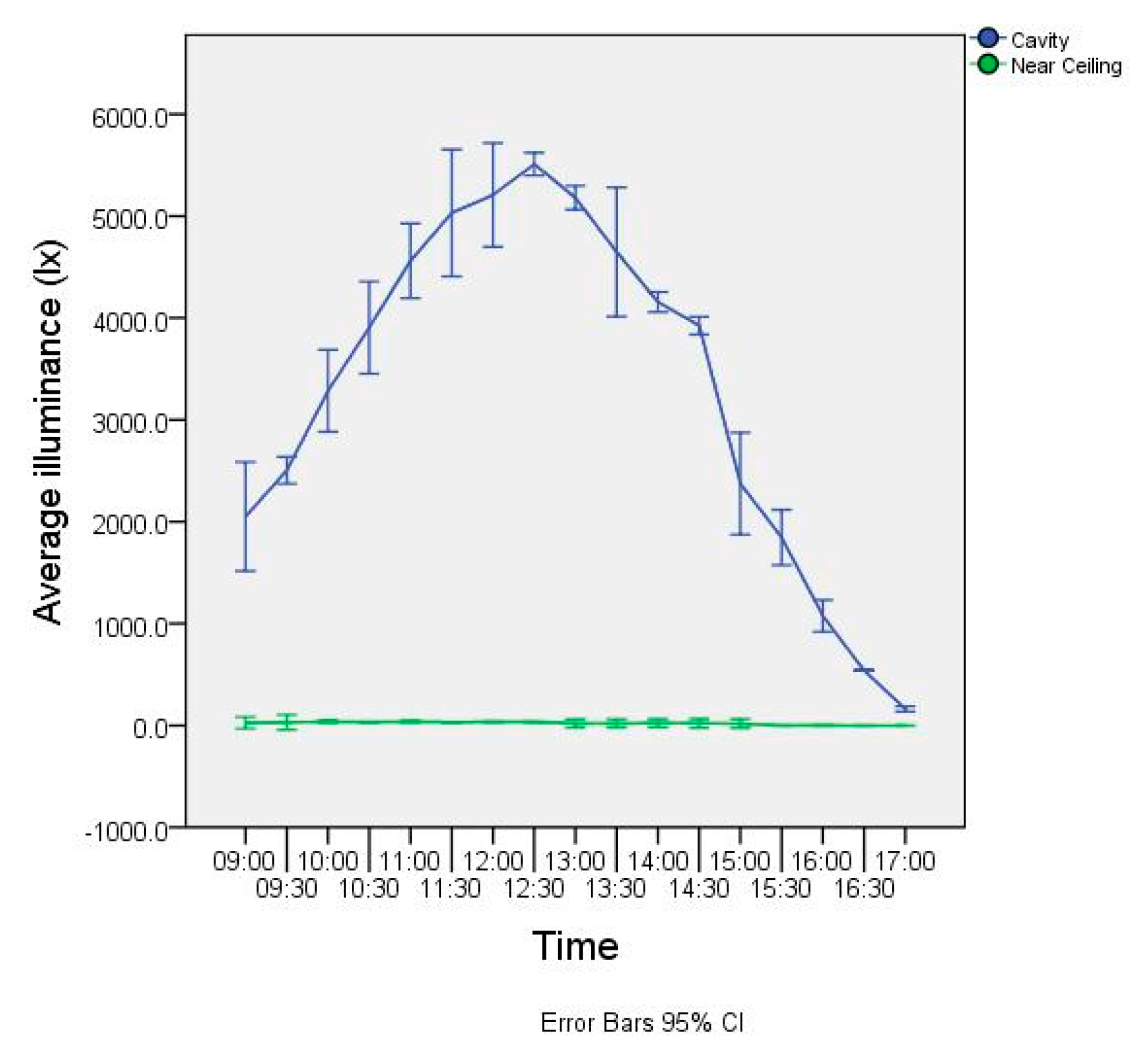
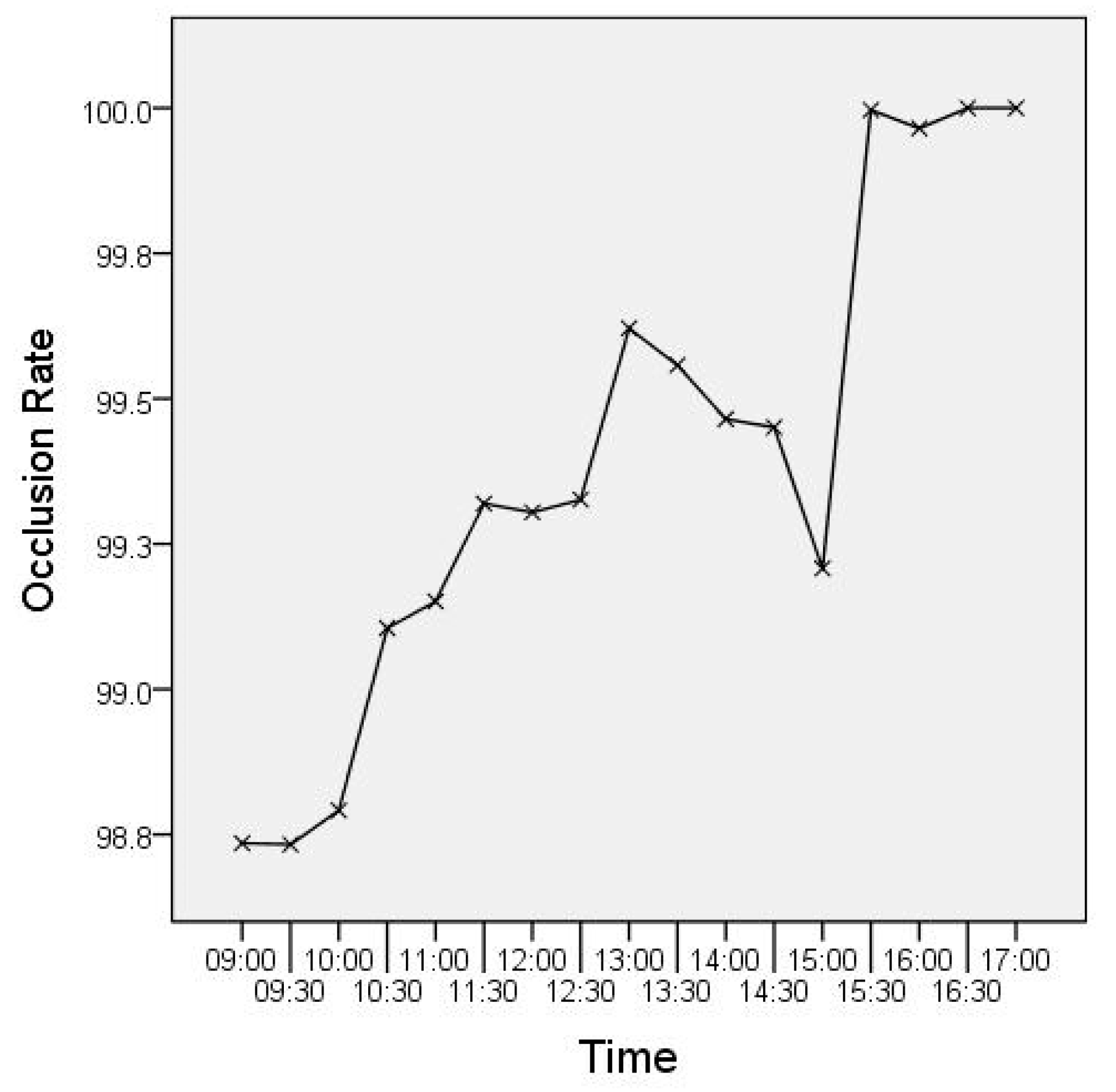
Figure 10. It can be seen that before 12:30 on the test day, the illuminance in the cavity increased with time; after 12:30, the illuminance in the cavity decreased with time; at 12:30, the maximum illuminance appeared, 5510 lx, the difference between maximum and minimum values 5338 lx. The illuminance near the ceiling changed with time, the change was small, and the indoor illuminance was relatively stable while the difference between maximum and minimum values was only 3.2 lx, and it was not easily disturbed by outdoor light changes. Therefore, it can be seen that after using the shielding material, the light environment in the internal space was relatively stable. The result in
Figure 10 shows that the solar occlusion rate of the shielding material was above 98% on average, which achieves the ideal shielding effect.
3.2. Influence of Ceiling Shielding Materials on Temperature
The temperature change of each measuring point is shown in
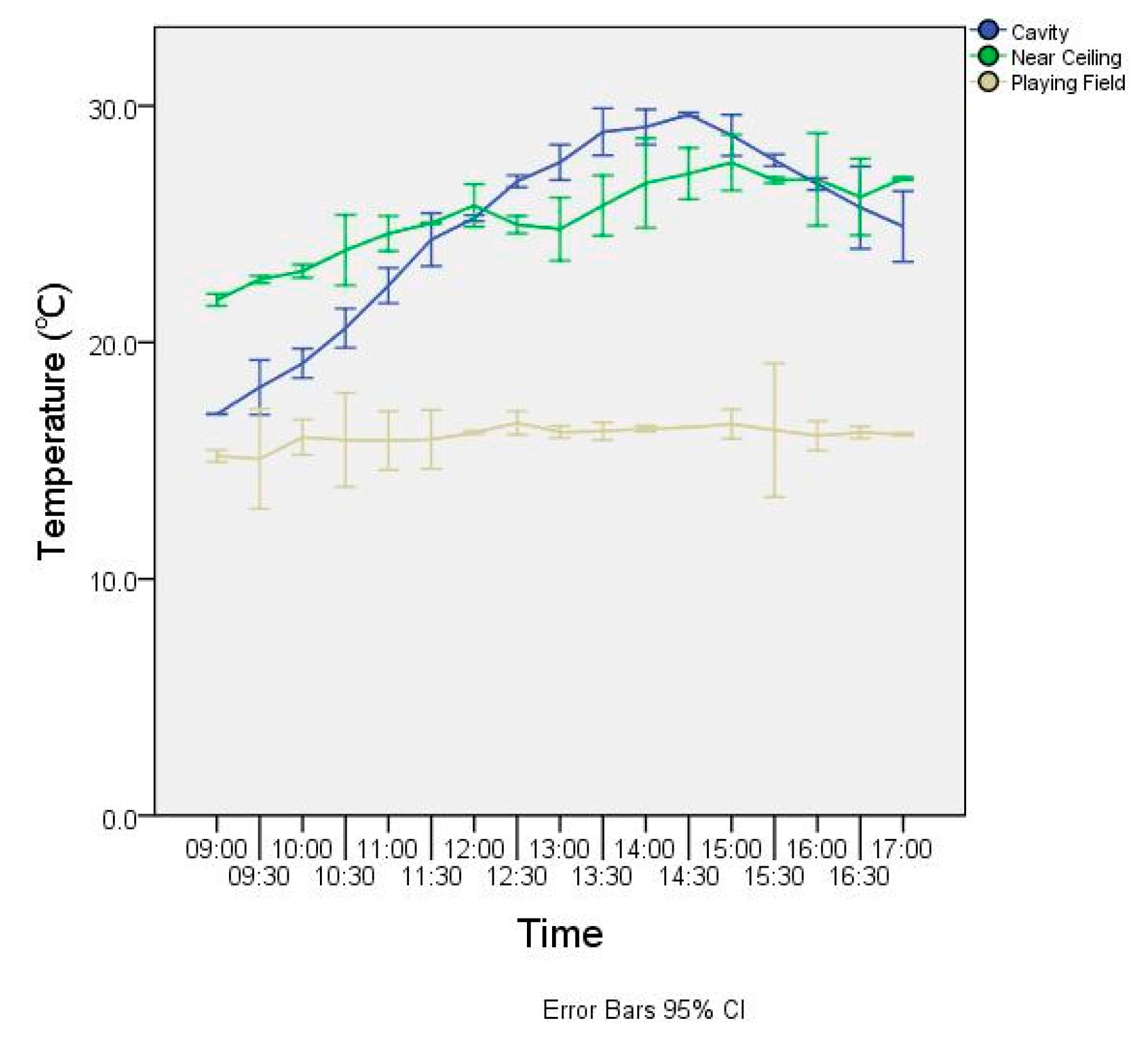
Figure 11. In the test time range, the temperature of the cavity first rose and then declined from morning to afternoon, and the maximum value appeared at 14:30, and the temperature in the cavity changed greatly. The lowest temperature was 17.0 °C and appeared at 9:30, the highest temperature was 29.6 °C and appeared at 14:30; the difference was 12.6 °C. The temperature change near the ceiling was similar to that of the cavity, and it also showed a trend of rising first and then decreasing, but the temperature change near the ceiling was smaller, and it was relatively stable compared with the temperature in the cavity. Before 12:00 and after 16:00, the temperature near the ceiling was higher than the temperature in the cavity, and the temperature the rest of the time was lower than the temperature of the cavity, so the shielding material could maintain the thermal stability of the indoor space. The change trend of the playing field temperature was relatively gentle: the highest temperature was 16.6 °C, the lowest temperature was 15.1 °C. The difference was only 1.5 °C; the difference was 11.9% of the temperature fluctuation in the cavity, indicating that the thermal stability on the playing field was good and meets the environmental requirements of ice sports.
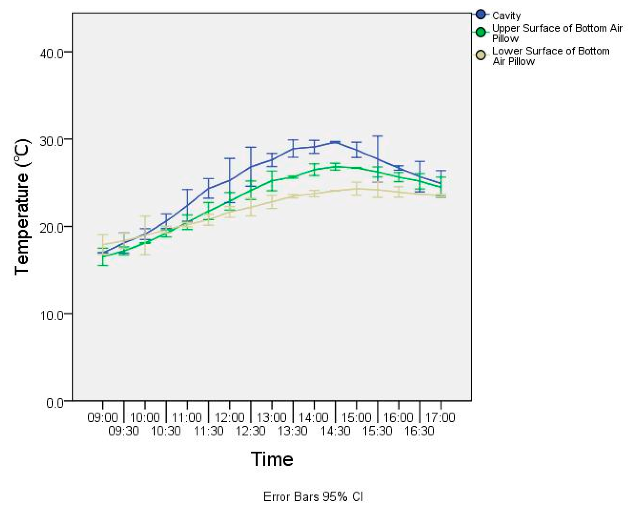
Since the shielding material was placed on the upper surface of the bottom air pillow, the cavity temperature, the upper surface temperature, and the lower surface temperature of the air pillow were analyzed, and the results are shown in
Figure 12. It can be seen that the three temperatures show a consistent effect, all showing a trend of rising first and then falling within a certain period of time. The difference is that the magnitude of the change is more obvious. The difference of the cavity temperature was 12.6 °C, the difference of the upper surface of the bottom air pillow was 10.3 °C, and the difference of the lower surface of the bottom air pillow was 6.3 °C. Comparing the standard deviation, the cavity was 4.04 while the near ceiling and playing field only 1.71 and 0.40, indicating that as the vertical direction moves down, its thermal stability gradually increases, and the shielding material has an obvious maintenance effect on the indoor thermal stability.
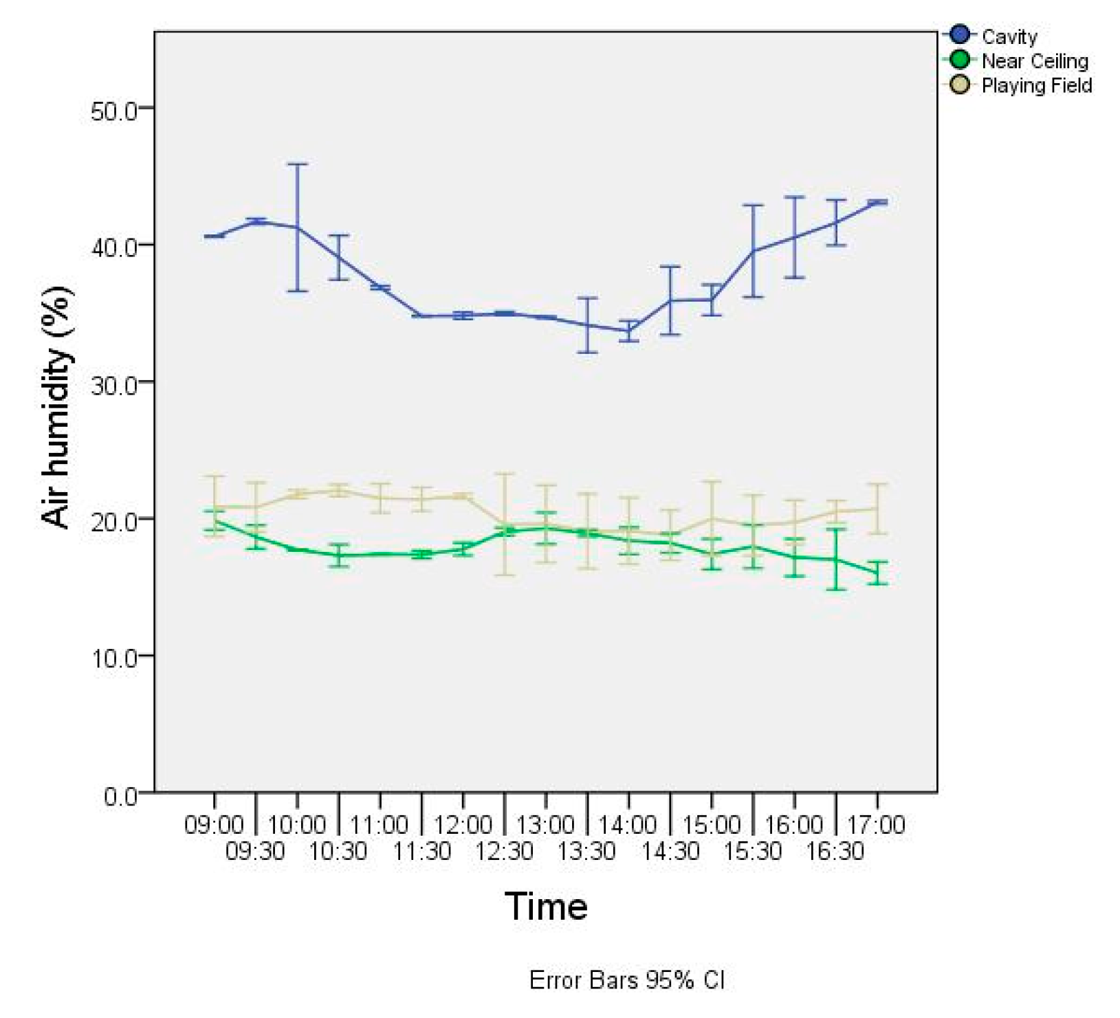
3.3. Influence of Ceiling Shielding Materials on Indoor Air Humidity
By measuring the humidity in the cavity, near the ceiling, and at the playing field at different times, the effect of the shielding material on the humidity was obtained. The analysis results are shown in
Figure 13. In the test time range, the humidity in the ceiling cavity was large: the maximum value was 43.1%, the minimum value was 33.7%, the standard deviation is 3.19. The humidity near the ceiling was close to the field, the change is relatively small, and the value was approximately in half, of which the standard deviation is only 0.96. The playing field humidity was slightly greater than that of the ceiling where the standard deviation was 1.04. The shielding material had a positive effect on indoor humidity control. Due to the heat accumulation of the shielding material, the difference between the temperature of the lower surface of the ceiling and the indoor temperature is small, and the ceiling was not prone to condensation.
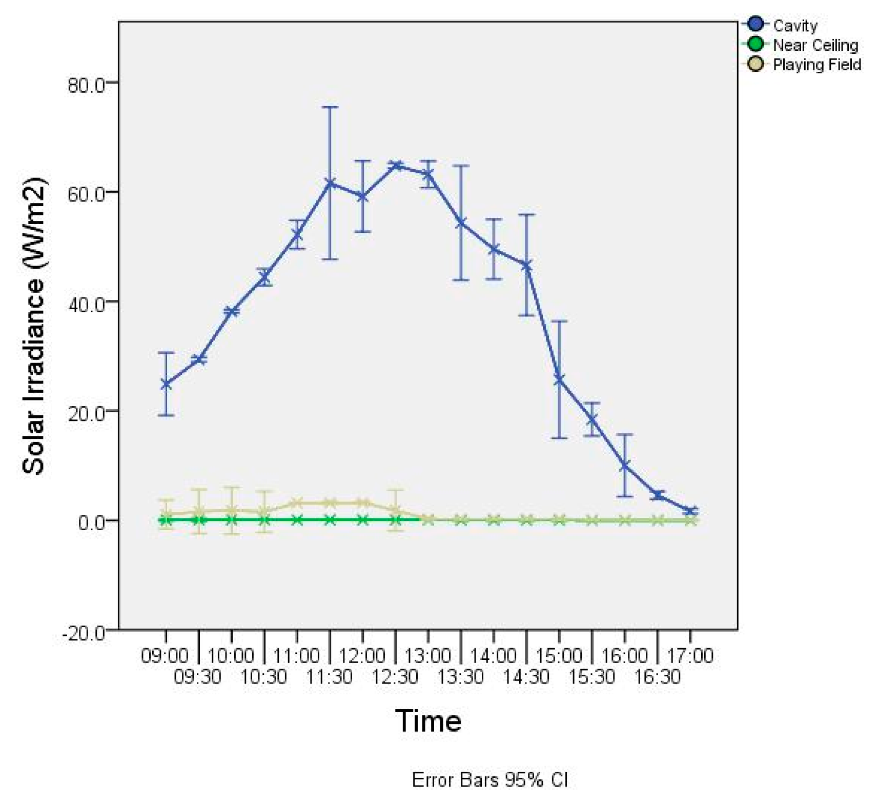
3.4. The Influence of Ceiling Shielding Materials on Solar Irradiance
The test results of solar irradiance at each measuring point are shown in
Figure 14. It can be seen that the solar irradiation in the cavity was larger within the test time range. With the increase of time, the solar irradiation value first increased and then decreased. Compared with the solar irradiation of the cavity where the maximum value was 64.8, the minimum value was 1.7, and the standard deviation was 21.02. The irradiation near the ceiling was far lower: where the maximum value was 0.1, the minimum value was 0.0, and the standard deviation was only 0.04. The solar irradiation near the ceiling was only less than 1% of the solar irradiation in the cavity at the same time, so the ceiling shielding material could block more than 99% of the solar irradiation. Due to the artificial light source, the irradiance value of the site shows irregular changes, so we will not make too many comparisons here.
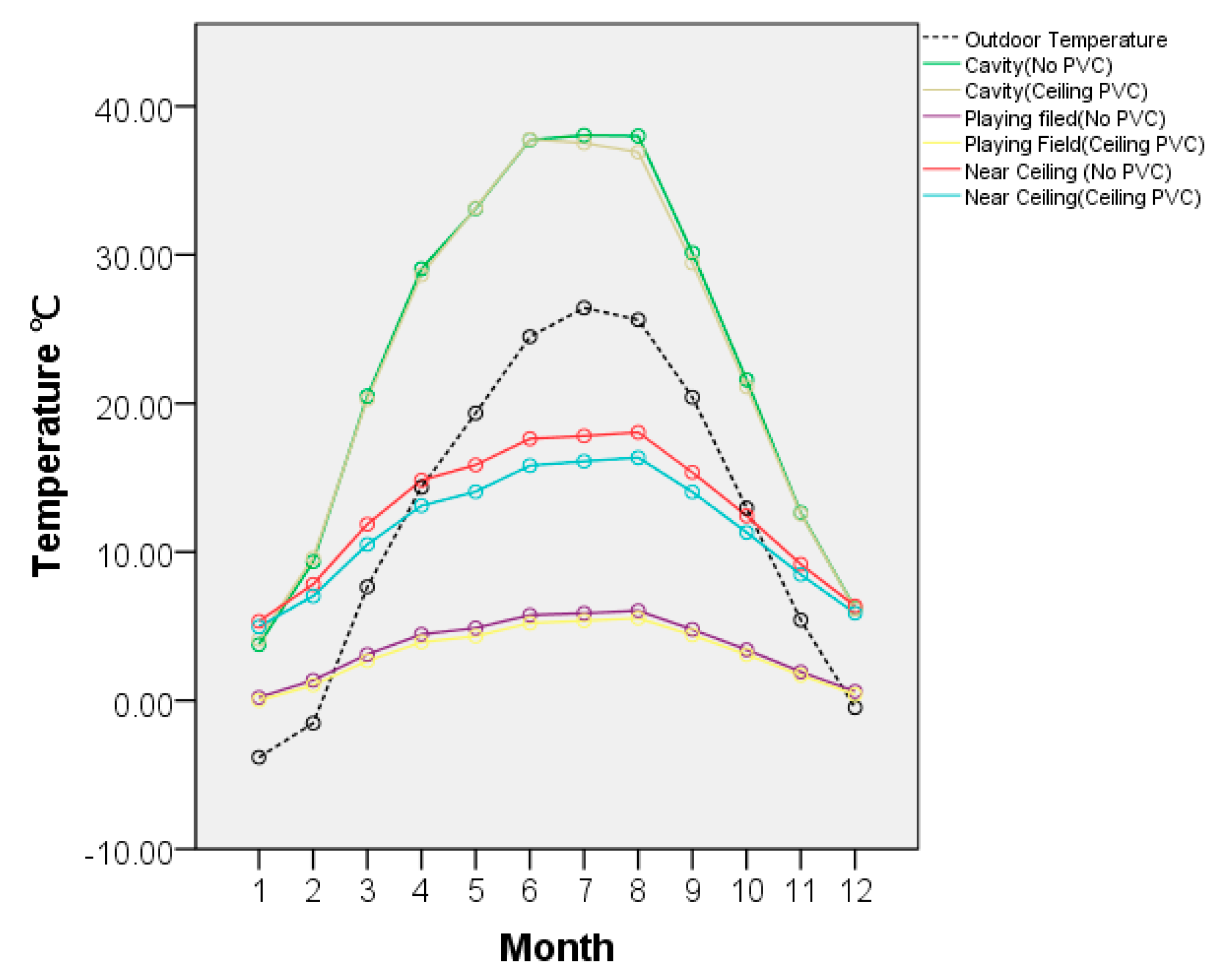
3.5. The Simulation before and after PVC Coating
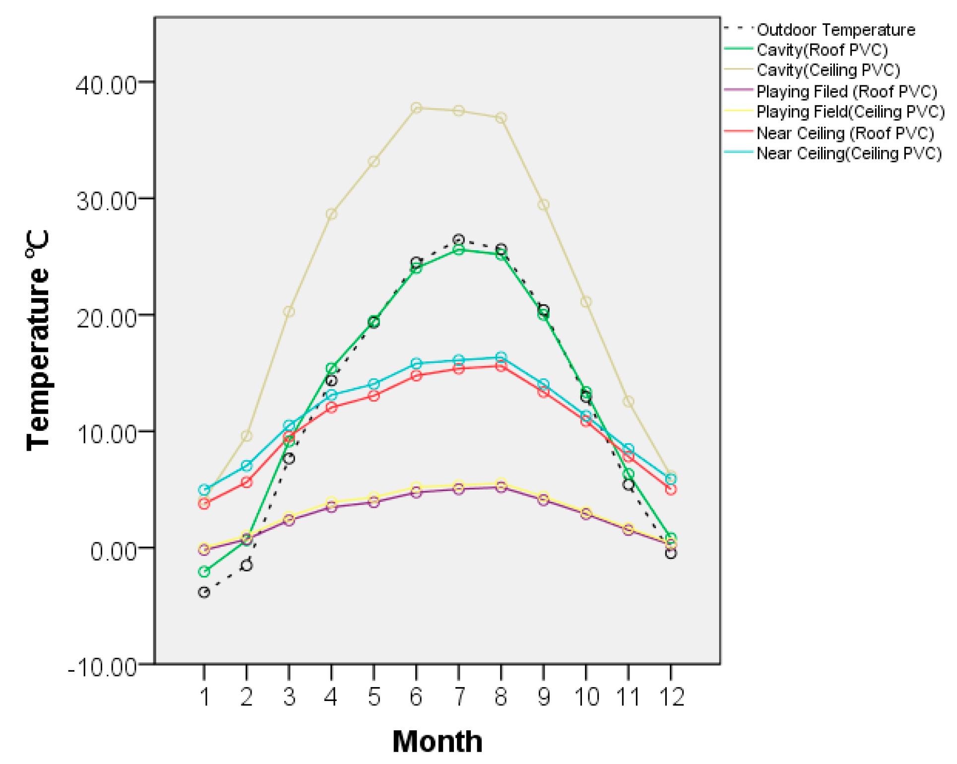
According to the first simulation, it can be seen in
Figure 15 that compared with no PVC coating, the indoor temperature of each zone decreased throughout the year. The temperature of the cavity decreased the least; the annual average drop was only 0.3 °C. The temperature near the playing field also decreased 0.5 °C, which is relativity small. The temperature near the ceiling decreased most, and it decreased 1.3 °C.
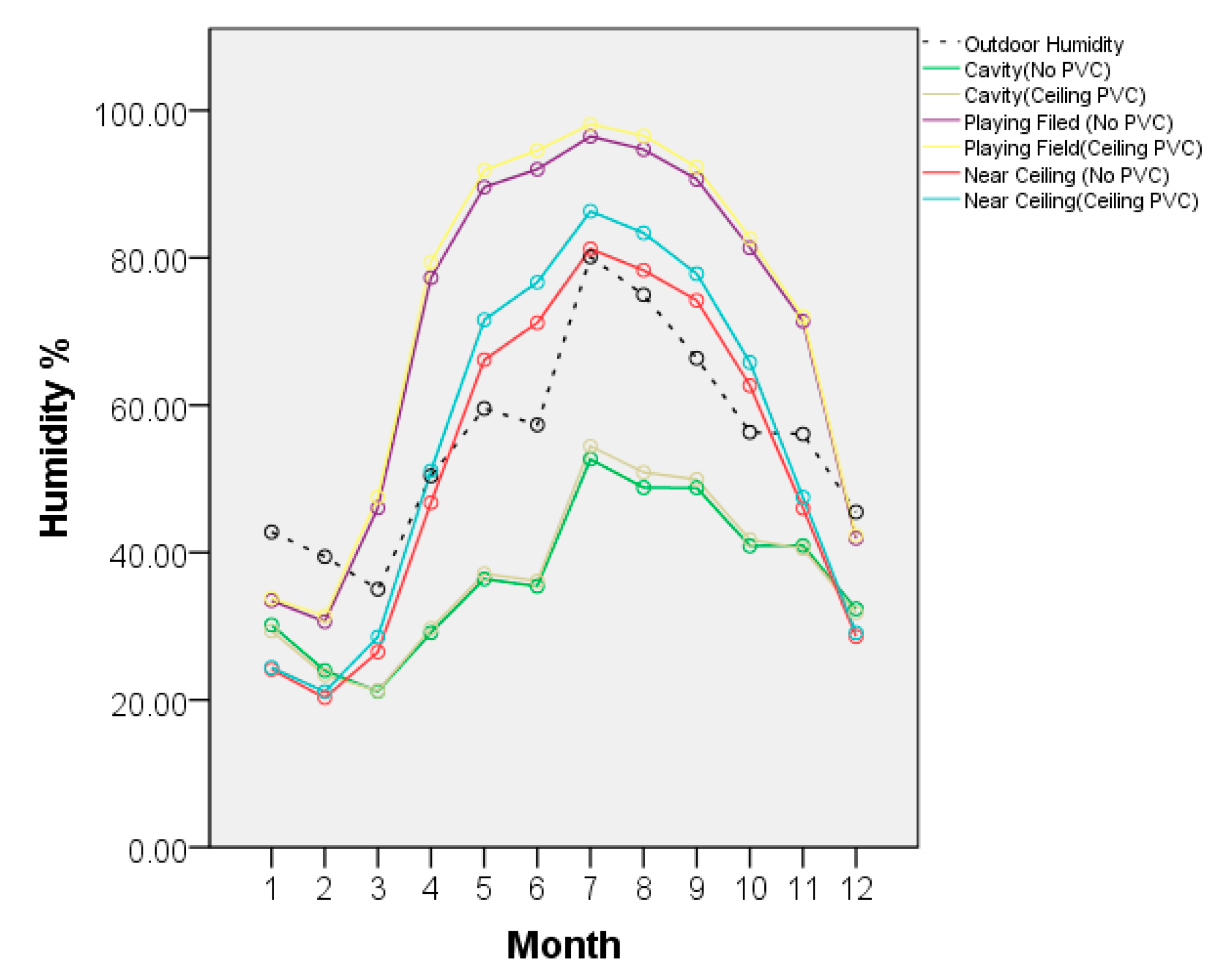
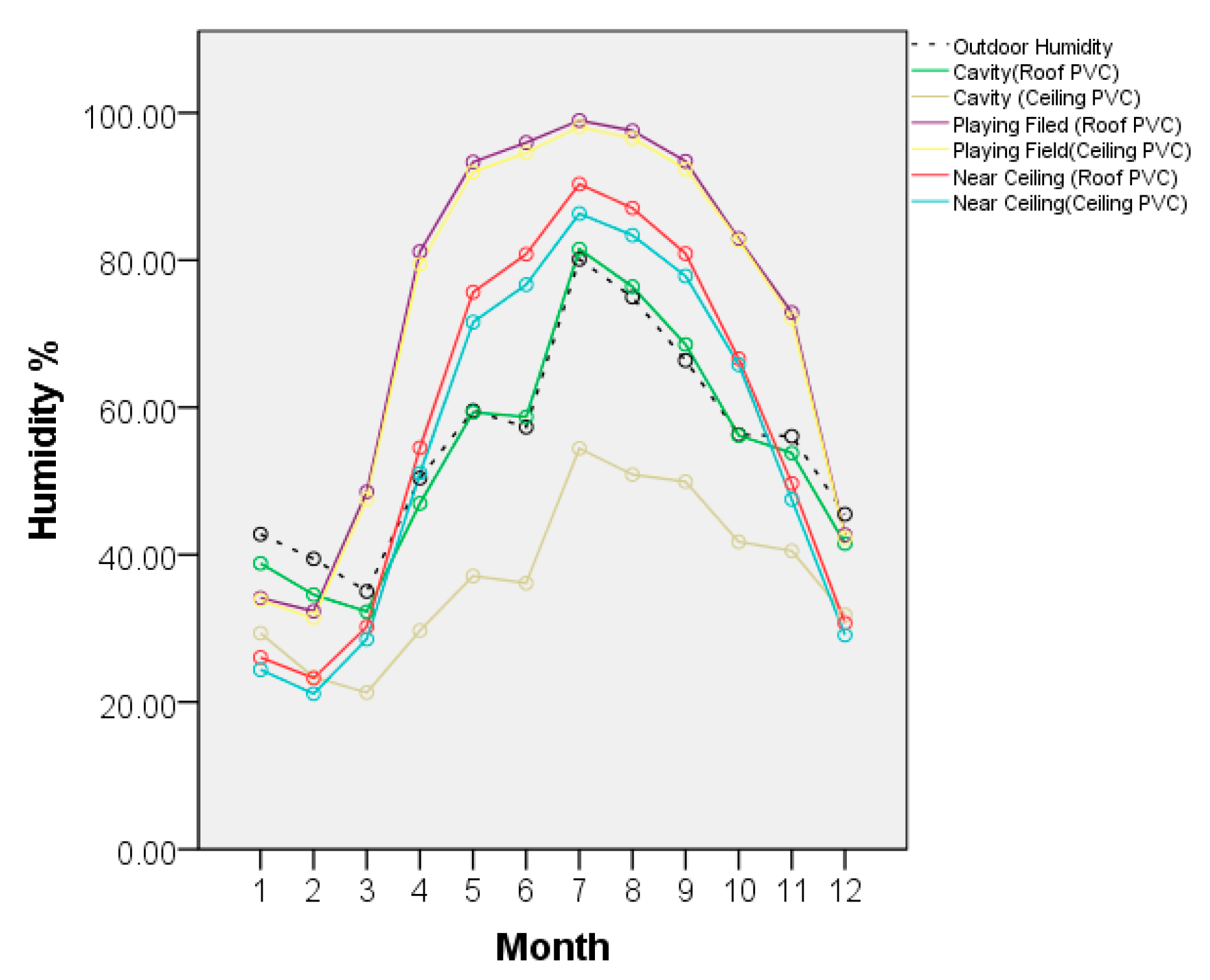
As for the relative humidity, it was similar to the temperature as shown in
Figure 16. After coating, the humidity of the cavity increased less, and the average humidity increased 0.4%, the near ceiling rose the most reaching 3%, while near the playing field rose only 2%.
Since the PVC coating is black, opaque, and can absorb most of the solar radiation, the sunlight cannot enter the building inside so that the solar radiation indoor was reduced. Compared with no PVC coating, due to the reduction of solar radiation, the internal temperature was reduced as well. The cavity was reduced by 1.5%, the area near the ceiling was reduced by 10.2%, and the playing field was reduced by 11%. Similarly, because the PVC coating can prevent the internal heat radiation from flowing out, the internal temperature change was also small, which improved the thermal stability of the building. In addition, after adding the PVC coating, the temperature inside the building space decreased, and the saturated humidity dropped, causing the relative humidity to rise.
3.6. The Simulation of Different PVC Coating Positions
According to the second simulation, as shown in
Figure 17, the effect of PVC coating on the roof and the on the upper surface of the lower air pillow was quite different. Among the two different placements, laying the PVC coating on the roof had a more obvious effect on reducing indoor temperature. As for the temperature of the cavity, the coating placed on the roof was 10 °C lower than on the upper surface of the lower air pillow. The temperature near the ceiling also differed by 2.2 °C, with the temperature near the playing fielding also 0.7 °C lower than that on the upper surface of the lower air pillow. This shows that laying the PVC coating on the roof can better maintain the thermal stability of the building and reduce the indoor temperature. However, because the coating is directly exposed to the air, thus easily affected by external conditions when placed on the roof, its durability is relatively poor, and it is relatively inconvenient to disassemble and install compared to another, so the overall economic benefit is to choose the upper surface of the lower air pillow to lay the coating.
As for the relative humidity, as shown in
Figure 18, the position of different PVC coatings had a dramatic effect on the humidity inside the building. On the whole, when the PVC coating was on the roof, the humidity of each space was higher than that of the PVC on the upper surface of the lower air pillow. Among them, the humidity near the ceiling was the largest difference, reaching 17%; the minimum on the ground was only 1%; and the humidity near the ceiling was 3%.
Since the PVC coating place was different, the result was also quite different. If the coating is placed on the roof, the external solar radiation will not enter the interior of the building. A large amount of solar radiation was absorbed and reflected due to the PVC coating, and the solar radiation decreased sharply from the roof, so the temperature in the cavity was relativity lower. When the PVC coating is placed on the upper surface of the lower air pillow, the solar radiation can still enter the cavity, but it was absorbed and reflected at the ceiling, so the temperature of the cavity did not drop significantly. Compared with the PVC coating on the roof, the temperature of the building cavity was 121% higher than the PVC coating on the roof while near the ceiling and playing field, the temperature of PVC coating on the roof was 10.1% and 9.2% lower.
3.7. The Simulation of Different Thicknesses PVC Coatings
According to the third simulation, as shown in
Table 6, different PVC coating thicknesses have less influence on the results. Among them, the temperature of playing filed under the 3 mm coating was the lowest, but the monthly difference was only 0.01 °C at most, which is almost the same. Therefore, when choosing the thickness of the PVC coating, choosing thinner and lighter materials may be a good way.
As for the relative humidity, it can be seen that different PVC thicknesses have minimal impact on building humidity. The humidity difference in each space of the building was less than 0.1%, so the influence of PVC thickness on humidity can also be ignored. According to the economic principle, the good choices are also thin and lightweight materials.
Although different thicknesses of PVC coatings were used for simulation, the difference was very subtle. The reason is that PVC coatings mainly rely on absorbing and reflecting solar radiation to achieve indoor cooling and maintain indoor thermal stability as
Figure 7. As the PVC coating was very thin, the thermal conductivity was only 0.14 W/m·K, and the density was very small, only 80% of the ETFE. So, if increasing the thickness of the PVC coating by 1 mm or 2 mm, the thermal performance impact is relativity small. Therefore, the temperature and humidity of each space of different thicknesses of PVC are basically the same.
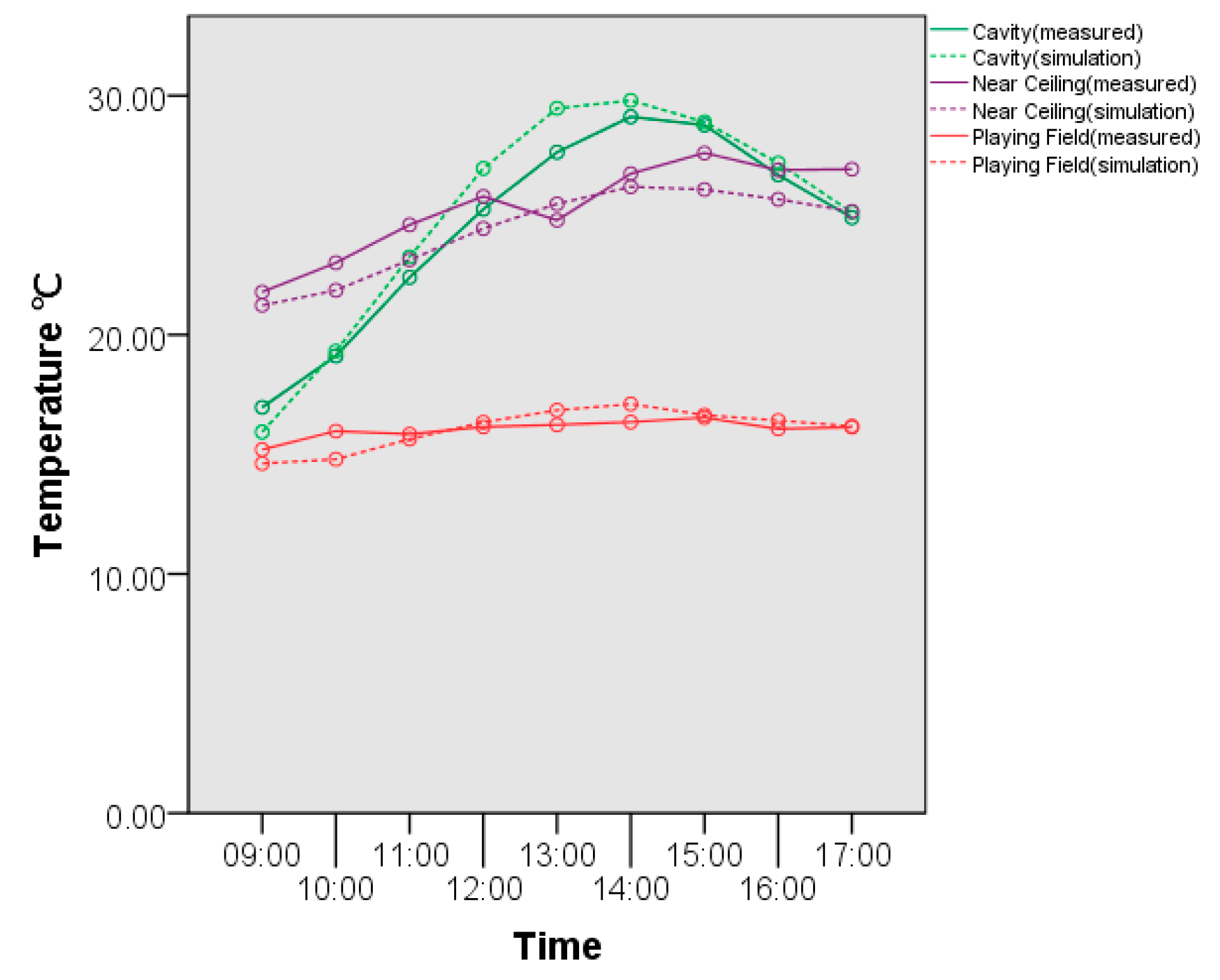
3.8. Comparison of Simulated Data and Measured Data
According to the third simulation, different PVC coating thicknesses have less influence on the result. By comparing the simulated data with the measured data as shown in
Figure 19, the simulated data selected the average temperature from 7 January to 9 January. As the intention of the simulation was to only study the impact of PVC coating on the thermal and moisture performance of the building, heating and air conditioning were not designed and not simulated. During the actual measurement, there were heating and air conditioning reasons in the space, so the simulation data were corrected by coefficients, and then compared with the measured data.
Through comparison, it can be found that in each space in the building, the difference between the measured data and the simulated data was small: the maximum error was only 2 °C, accounting for 7%, and the change trend of the data was consistent. Therefore, it shows that the results of the actual measurement and the simulation are consistent, and the simulation is reliable and accurate.
4. Conclusions
Laying detachable PVC coating in the ETFE air pillow cavity can effectively block the transmission of sunlight, and the shielding rate of the shielding material to the natural visible light is as high as 98%. As for the indoor air temperature, laying the coating can reduce the indoor temperature from 1.5% to 11%, and stabilize the indoor thermal and humid environment. Although laying the PVC coating on the roof can better maintain the thermal stability of the building and reduce the cavity temperature more than 10℃, due to the construction and durability, laying the PVC coating on the upper surface of the lower air pillow is a better solution. Meanwhile, because the PVC coating is very thin, the thermal conductivity is only 0.14 W/m·K and the density is only 80% of the ETFE, so increasing the thickness of the PVC coating does not influence much; thus a 1 mm PVC coating is enough. The research expands the venue’s post-match use to realize seasonal conversion of the stadium function between the summer and winter, and provides a data source for the research of ETFE air pillow membrane structure.


