Review

Fresh and Hardened Properties of Extrusion-Based 3D-Printed Cementitious Materials: A Review

1
Department of Civil and Environmental Engineering, The Pennsylvania State University, University Park, PA 16802, USA
2
School of Civil Engineering, Harbin Institute of Technology, Harbin 150090, China
3
Department of Civil, Construction, and Environmental Engineering, The University of New Mexico, Albuquerque, NM 87131, USA
4
Department of Architecture Engineering, The Pennsylvania State University, University Park, PA 16802, USA
5
Department of Architecture, The Pennsylvania State University, University Park, PA 16802, USA
6
School of Engineering Design, Technology, and Professional Programs, The Pennsylvania State University, University Park, PA 16802, USA
*
Author to whom correspondence should be addressed.
Sustainability 2020, 12(14), 5628; https://doi.org/10.3390/su12145628
Submission received: 17 June 2020 / Revised: 8 July 2020 / Accepted: 10 July 2020 / Published: 13 July 2020

Abstract

:
3D-printing of cementitious materials is an innovative construction approach with which building elements can be constructed without the use of formwork. Despite potential benefits in the construction industry, it introduces various engineering challenges from the material point of view. This paper reviews the properties of extrusion-based 3D-printed cementitious materials in both fresh and hardened states. Four main properties of fresh-state printing materials are addressed: flowability, extrudability, buildability, and open time, along with hardened properties, including density, compressive strength, flexural strength, tensile bond strength, shrinkage, and cracking. Experimental testing and effective factors of each property are covered, and a mix design procedure is proposed. The main objective of this paper is to provide an overview of the recent development in 3D-printing of cementitious materials and to identify the research gaps that need further investigation.

1. Introduction

3D-printing, more formally known as additive manufacturing (AM), is defined as “fabrication of objects through the deposition of a material using a print head, nozzle, or another printer technology” [1]. It has been used successfully in a wide variety of disciplines, such as aerospace, automotive, biomedical, energy, and food industries [2,3,4]. It is believed to enable the next industrial revolution because of the quick and cheap production of objects from simple to intricate designs and geometries. Over the last few years, several 3D-printing technologies have also been developed for building and construction. Compared to conventional methods of construction, 3D-printing has the potential for automation; reduction of construction cost (in terms of labor and formwork), time, material waste, and energy; and fabrication of geometrically complex structures [5,6]. It is an attractive alternative for both on-site and off-site construction applications.
Generally, 3D-printing technologies used in the construction industry can be roughly classified into two major groups: powder-based and extrusion-based printing [7,8]. With the powder-based printing technique, a liquid binder material is deposited selectively to a powder layer (e.g., sand) so that the desired object is bonded together after repeated process layers [9]. A typical example of powder-based printing technology in construction is provided by the company D-shape [10]. Despite its advantages of high printing resolution, as well as considerable geometric freedom, the powder-based technique builds up each layer at a relatively slow printing speed, and thus, it is more suitable for off-site and small-scale manufacturing, such as fabrication of panels, permanent formworks, interior structures, and other building components [7,8]. In addition, due to the particular binding process, only a small range of cementitious materials, mainly fast-setting ones, such as rapid-hardening portland cement [11], calcium aluminate cement [12,13,14,15,16], magnesium-based Sorel cement [10], gypsum [13,14,17,18], and geopolymer [7,19,20] have been utilized for powder-based 3D-printing. For a comprehensive review of powder-based printing, see Lowke et al. [9].
For the exploration of both on-site and off-site large-scale manufacturing applications, this paper focuses exclusively on the extrusion-based printing process, another typical 3D-printing technique in automated construction, which extrudes printable cementitious materials layer by layer in the form of filaments from a nozzle mounted on a robotic control system (shown in Figure 1). Examples like Contour Crafting [21,22,23], Concrete Printing [24,25], CONPrint3D [26], and the PennStateDen@Mars Project [27,28,29,30,31] (see Figure 2) illustrate the potential use of extrusion-based printing technology for large-scale freeform construction. However, there are some concerns about the quality of printable mixtures, which are quite different from cast-in-place concrete.
In traditional construction techniques, formwork is commonly used for the temporary support of cast-in-place concrete, whereas in 3D-printing of cement-based materials, they are extruded layer by layer without the use of formwork. Explicitly, the material must maintain its shape and sustain subsequent layers after extrusion. Lack of conventional vibrating compaction during the printing process also leads to anisotropic (namely, direction-dependent) properties of the printed components. Therefore, both fresh and hardened properties of the printing materials are critical for the quality of the printed components.
In 2012, the first systematic study on properties of the printable cementitious materials in fresh and hardened states was reported by Le et al. [32,33]. The authors successfully developed a high-performance printable mortar for the 3D-printing process, which provided a preliminary guideline for other researchers. Since then, an increasing number of studies addressing the specific properties of cementitious materials compatible with 3D-printing technology have been published, with the goal of developing the printable materials for freeform construction.
Although a few review papers on this topic can be referred to [34,35,36,37,38,39], this paper contains a much more detailed discussion on the fresh and hardened properties of 3D-printable cementitious materials, especially their definitions, experimental testing, and internally/externally effective factors. Section 2 covers the fresh properties, including flowability, extrudability, buildability, and open time. The evolution of rheological properties that are related to fresh properties is further explained. Section 3 presents thorough descriptions of the hardened properties, such as density, compressive strength, flexural strength, tensile bond strength, shrinkage, and cracking. Existing reinforcement methods are also discussed. In Section 4, a summary of experimental testing and effective factors for each property is provided, and a step-by-step mix design procedure is proposed. Finally, Section 5 identifies future research needs in 3D-printed cementitious materials.

2. Fresh Properties

Unlike conventional cast-in-place concrete, the cementitious materials 3D-printed without the use of formwork are expected to be low or no-slump [40,41,42,43], and thus, stiff enough to maintain stable printed geometries. Due to the difference between conventional construction methods and the novel concrete printing process, it is important to consider the fresh properties of 3D-printed cementitious materials in accordance with the innovative printing technique.
In most existing literature, flowability, extrudability, buildability, and open time are investigated as the main properties of the printing materials in the fresh state [32,44,45,46]. Flowability and extrudability are the critical parameters utilized to evaluate material flow behavior during pumping and extrusion. Although these two properties seem to be interrelated, it should be noted that flowability emphasizes the material’s ability to move smoothly from the mixer to the printing nozzle, whereas extrudability focuses more on the capacity of fresh paste to come out of the nozzle as a continuous filament with the desired thickness and width. Buildability, another important parameter, indicates whether a printed filament can retain its extruded shape under load from itself, subsequently deposited layers, and extrusion pressure. Lastly, open time is related to the time in which the freshly mixed materials maintain consistency (ease of flow) for smooth transportation and desirable extrusion.
Two contradictory demands for the printable mixture limit the development of construction-scale 3D-printing. First, the cementitious paste is expected to be “fresh” enough to be transported in the printing system and extruded through the printing nozzle, whereas it must be stiff and have sufficient buildability to maintain its shape right after extrusion. Second, a long open time is beneficial to continuous extrusion, as well as good interlayer bonding, but it is detrimental to shape stability of printed objects with respect to buildability [32].
Some researchers [32,47,48] have regarded the flow behavior of materials as workability instead of flowability when investigating fresh properties of 3D-printed cementitious materials. However, it is unsuitable to describe flow behavior simply as workability. Although there has been a disagreement about the definition of workability [49,50,51], the term “workability” generally refers to various properties of fresh concrete during the conventional casting process (in which the materials are mixed, transported, placed, compacted, and finished). In terms of the novel concrete printing process, workability (or, more precisely, printability) should be defined as the property determining the printable performance of a cementitious mixture. It is a composite property, with at least four principal components mentioned above (i.e., flowability, extrudability, buildability, and open time).
All the fresh properties depend on the material mixture design and the printing system (especially the mixing and pumping systems, as well as the printing nozzle. The effects of these influential parameters on the four key fresh properties and the evolution of the corresponding rheological properties are discussed in the following sub-sections.

2.1. Flowability

Flowability, or pumpability [24,52,53], is a critical property that evaluates the flow behavior of fresh materials in the pumping system. Adequate flowability enables smooth transportation of the materials from the mixer to the printing nozzle.

2.1.1. Experimental Testing

Flowability can be investigated qualitatively by a few simple testing methods, especially the slump flow test [44,45,54,55] and the flow table test [46,48,56,57,58,59,60,61]. Supplementary information about viscosity and buildability (Section 2.3) can be obtained by V-funnel test [46] and squeeze flow test [55,62]. These methods are simple and commonly used for the gross measurement to indicate how the cementitious paste would flow in the printing process.
In the majority of recent studies [26,43,48,54], the rheometer test was utilized to characterize material flow behavior from a quantitative perspective, providing the intrinsic rheological parameters, such as yield stress and plastic viscosity. Yield stress τc is the critical shear stress above which flow initiates. It can account for the results of the slump flow test [63]. Plastic viscosity µ is defined as the resistance to flow, which relates shear stress τ to shear rate γ after the initialization. The flow behavior of fresh cementitious materials is often described as visco-plastic materials based on the Bingham model, i.e., τ = τ c + µ γ . For high fluidity, the material yield stress and viscosity should be as low as possible.

2.1.2. Effective Factors

From the point of view of mix design, additives (e.g., chemical and mineral admixtures and reinforcing fibers) are the main factors affecting the flowability of fresh-state cementitious materials. Chemical admixtures, such as superplasticizers and retarders, are commonly employed to better control the flowability of freshly printed mixtures. Superplasticizers provide an improvement in flow [32,44,45,57], whereas an excessive amount reduces the buildability significantly [44]. Additionally, a retarder would be helpful for ensuring a constant flow in the printing machine [32,44,47]; however, it postpones the stiffening rate (structural rate), and as such, the layer build-up process. Air-entraining admixtures, which provide durability for hardened concrete at freezing and thawing temperatures, can also affect the flow behavior of fresh concrete [64,65,66]. Zain et al. [67] observed that an air content between 1.5 and 2% is appropriate to maintain the flowability, but excessive air content decreases the flowability. It should be noted that the influence of air-entraining admixtures on 3D-printable cementitious materials has not been taken into account in most existing literature.
The addition of mineral admixtures, such as fly ash, silica fume, and slag, is also a practical approach to control the flowability of fresh paste. This is based on the effect of particle size, shape, pozzolanic nature, and content of mineral admixtures. An appropriate proportion of aggregate, cement, and mineral admixtures enables a wider particle size distribution, making it possible for the fresh mixture to achieve good flowability [68,69]. The spherical shape of fine mineral admixtures also contributes to the flowability by reducing inter-particle friction [70,71,72] and fluid demands [73]. Due to the small size and round particle morphology, Rushing et al. [57] reported that the inclusion of fly ash increases the flowability of the printing concrete mixture. However, the addition of silica fume in the printing mixtures decreases the flowability in most cases [48,57,60] despite a promotion of compressive strength [56], which may be mainly attributed to its pozzolanic activity and very fine particle size (high specific surface area compared to cement leading to high water absorption, and thus, low flowability of mixtures). Also, an excess content of fine mineral admixtures (i.e., over the critical content at which maximum packing density is reached) may increase the specific surface area of particles and the viscosity of mixtures [71], resulting in decreased flowability.
Reinforcing fiber, as a useful reinforcement method for 3D-printable cementitious materials, has an adverse impact on material flow behavior [74,75,76]. According to Zareiyan and Khoshnevis [60] and Shakor et al. [77], the inclusion of fiber decreases the flowability of 3D-printed concrete. Conversely, Rushing et al. [57] reported that adding 0.46 vol. % short reinforcing fibers (i.e., 0.5-in.-long steel or nylon fibers) to the printed concrete increases flowability compared with the control mixture to some extent, and that the mixture containing steel fibers flowed better than that containing nylon fibers.
In addition to the mix ingredients discussed above, there are external factors contributing to the flowability of printable materials, such as the mixing and pumping systems, and ambient conditions (i.e., temperature and relative humidity). For example, the time interval between mixing and pumping would influence the flowability of the fresh mixture. The flow behavior varies depending on the specific pumping system, including pump pressure, pumping distance, and size and geometry of the pumping hose [78,79]. Additionally, since the rheological parameters, particularly viscosity, are highly temperature-dependent, ambient conditions are influential factors in the flowability of fresh materials.

2.2. Extrudability

In 3D-printed cementitious materials, extrudability can be defined as the capacity of fresh paste to pass through the printing nozzle as a continuous and intact filament [32,44,45,47]. Even though excellent flowability is an essential prerequisite for adequate extrudability, a smooth flow of the material in pumping hoses cannot guarantee the desired extrusion through nozzles. This is because the size and geometry of hoses may not always be consistent with those of printing nozzles. For example, a rectangular or conical nozzle can lead to a blockage problem, due to the difference in cross-section between the pumping hose and the printing nozzle.

2.2.1. Experimental Testing

Three main characterization methods have been proposed to evaluate the extrudability of cementitious mixtures for 3D-printing. The first method is an assessment of printing distance over which the paste can be extruded out without blocking, segregating, or bleeding [32,44,47]. For example, Le et al. [32] evaluated extrudability by assessing the continuity and stability of the extruded filaments with a total length of 4500 mm from the printing nozzle. Secondly, a manual simulation test of 3D-printing has also been proposed to characterize extrudability. Khalil et al. [47] and Rubio et al. [80] used a simple modified gun as the manual device, whereas Rushing et al. [57] modified a clay extruder as the testing device. Fresh-state materials were loaded manually in both devices to simulate the extrusion process from the printing nozzle. A qualitative rating was assigned to each mixture depending on the relative ease with which it was extruded. Since the extrusion process is related to the flow behavior of the materials, extrudability can be characterized by the measurement of rheological properties [81,82], which is regarded as the third characterization method. Panda and Tan [43] studied the yield stress of materials to evaluate their extrudability using a rheometer. High static yield stress results in inadequate extrudability and blocking problems [83].
The first method tends to reveal the actual process of extrusion, while the third method is more likely to characterize extrudability as an intrinsic property of the mixture. These two methods are expected to be applied simultaneously in order to evaluate extrudability quantitatively. Without an apparatus to quantify the pressure manually applied to the paste, the second method (manual simulation test) can only provide a qualitative result. This method is simple but not recommended.

2.2.2. Effective Factors

To achieve good extrudability, it is wise to apply the principles of self-compacting concrete (SCC) and sprayed concrete to the mix design of 3D-printable cementitious materials, since the printed mixture has the advantages of both approaches (e.g., no need for compaction or formwork and transported through a pump under pressure). The principles require a smooth grading of materials with minimum void content and a high volume of cementitious paste for lubrication [32]. Le et al. [32] and Malaeb et al. [44] found that increasing the cement content and decreasing the sand content lead to better extrudability. Consistent with the observations of Rahul and Santhanam [84], Rushing et al. [57] reported that high coarse aggregate content causes interlocking of the aggregate, clogging in the printing machine, and bleeding of the printed concrete. Hence, a cement to fine aggregate to coarse aggregate ratio of 1:3:1 was chosen rather than that of 1:2:3 (the latter was described as a mix proportion for conventional concrete mixtures). Hambach and Volkmer [85] showed that the addition of a water-reducing admixture ensures smooth and continuous extrusion. They also found that excessive fiber content (over 1.5 vol. %) causes frequent blocking of the printing nozzle, which has a similar trend as observed by Rubio et al. [80]. Panda et al. [42] limited the fiber dosage up to 1 vol. % to avoid blockage and obtain good extrudability during the extrusion process. Ma et al. [46] proposed a new parameter, the extrudability coefficient (determined by flowability and rest time), to design and optimize mix proportions for printable materials. They also argued that the hydraulic conductivity of materials should be taken into consideration when adjusting the extrusion rate. If the rate is lower than the hydraulic conductivity of the materials, the liquid phase can flow through the granular skeleton, resulting in both paste hardening and blocking problems in the printing nozzle [86,87,88].
As for the printing nozzle, El Cheikh et al. [89] argued that a diameter ratio between the nozzle diameter and the maximum particle diameter larger than 4.25 avoids blocking during the extrusion. Based on their conclusion, it was reasonable for Le et al. [32] to select sand with a maximum grain size of 2 mm for a small nozzle with a diameter of 9 mm, which provides both high printing resolution and sufficient extrudability. It is noteworthy that a small nozzle sacrifices the efficiency of construction and restrains the use of coarse aggregates.
Apart from the size of the printing nozzle, its geometry would also influence the extrusion process. Roussel [53] elaborated on the difference in material flow behavior between rectangular and conical nozzles: The deposited material would experience laminar or non-laminar flow in a rectangular or conical nozzle, respectively. In the case of laminar flow, the material is deposited as a stiff and non-deformed filament, which is desirable to retain its shape, while for non-laminar flow, it expands once deposited despite easier extrusion than the former case.

2.3. Buildability

Buildability refers to the printed material’s resistance to deformation under load [24,32,45]. Without formwork, fresh materials must have sufficient buildability to be stiff enough after extrusion to sustain its self-weight, weight from the upper layers [36], and the extrusion pressure [56]. Otherwise, the high geometric accuracy of printed material cannot be achieved, and printed structures are highly prone to collapse.
One of the problems triggered by insufficient buildability is the deformation of the deposited layers in the vertical and horizontal directions, and thus, significant changes in the geometry of the printed component (displayed in Figure 3). This is due to fast printing in the height direction (short printing time interval between the successive layers for small scale printing) or low structural rate of the material (slow setting of the cementitious mixture). In this regard, material deformation should be taken into consideration when it comes to printing path design for high geometric accuracy of printed components [90].
Buildability failure by plastic collapse (a strength mechanism) and elastic buckling (a stability mechanism) of printed wall elements has been numerically studied [53,91,92,93,94,95,96]. During the printing process, the bottom layers have to sustain the gravity-induced stresses from the upper layers. When the stress in the bottom layer (maximum stress) reach the material yield stress, the printed wall may fail by plastic collapse. Elastic buckling is another failure mode for slender vertical structures reported in the literature. The elastic buckling failure can occur, due to progressive lateral deformations or eccentric layer placement. For the structure to be stable, the elastic modulus of the printed materials should exceed the critical value.

2.3.1. Experimental Testing

Buildability has been estimated in sprayed concrete by the horizontal build test [97], but for 3D-printed construction materials, there are no recognized testing methods of this parameter in the vertical direction [32,48]. Currently, two test methods are commonly used to directly or indirectly assess buildability of the printed cementitious materials.
The first method involves direct measurement of the layer height or number of layers that could be printed with minimum deformation or lowest risk of collapse [32,44,47,48,59]. This method is desirable for the in-situ test, due to its intuitive and quantitative results, as well as the simple testing process. However, it remains unclear how the degree of “deformation” or “collapse” is defined. To make up for this deficiency, two critical parameters—average vertical strain (the ratio of vertical deformation of deposited layers to the theoretical height) and height-to-width ratio of printed structures—have been developed to measure the buildability quantitatively [46]. Another method for indirectly investigating buildability concerns mechanical properties of fresh materials, including vertical deformation under load, green strength (i.e., strength immediately after extrusion), and rheological properties (especially yield stress). Panda and co-workers [43,98] conducted the plate stacking test to simulate incremental load on the lower layers and monitor the deformation behavior of the layers with no need to print, which is similar to the method presented by Perrot et al. [99], Kazemian et al. [56], Yuan et al. [100], and Shakor et al. [55,62]. Zhang et al. [48] measured the very early strength by the green strength test [101]. Likewise, other researchers [84,93,102,103] measured it by the unconfined uniaxial compression. As for rheological properties, Zhang et al. [48] evaluated viscosity, yield stress, and thixotropy (structure re-building of fresh paste) using the hysteresis loop test [104] with a rheometer to investigate their relationship with buildability. Perrot et al. [99] investigated yield stress to model the evolution of the mechanical strength of the printed materials. High yield stress ensures less deformation under load and sufficient buildability of the fresh paste [98,99].

2.3.2. Effective Factors

For conventional concrete, favorable dimensional stability can be achieved with high aggregate contents [105]. Similarly, for 3D-printing of concrete, Ma et al. [36] pointed out that a relatively high content of fine aggregate could lead to adequate buildability. Additives are also the main factors contributing to buildability. Malaeb et al. [44] reported that, as the amount of superplasticizer increases, the number of buildable layers decreases, even though flowability could be improved. Khalil et al. [47] mixed a small quantity of calcium sulfo-aluminate cement as a setting accelerator with ordinary portland cement to increase the short-term stiffening and achieve better buildability. Although the addition of an accelerator allows fresh materials to set and stiffen at a faster pace, it should be noted that the size of printed objects should be considered when choosing the content of accelerators. For small objects, a very short setting guarantees sufficient buildability of the printed objects. Conversely, for large structures, fast setting would cause issues like the formation of cold joints and weak interfaces, due to a comparatively low printing speed and a long printing time gap between layers.
Rushing et al. [57] and Rubio et al. [80] concluded that the inclusion of fibers improves the buildability of cementitious mixtures. Zhang et al. [48] found that inclusion of nano clay or silica fume enhances the yield stress, and as such, the buildability of the freshly printed materials, agreeing reasonably well with the research by Kazemian et al. [56] and Panda et al. [103]. Panda and Tan [43] reported that the addition of nano clay, microfibers, or ground granulated blast-furnace slag contributes to better buildability of a 3D-printable geopolymer.
When it comes to external factors, Malaeb et al. [44] argued that side and top trowels installed on a printing nozzle create smooth surfaces, ensuring maximum buildability. As for the geometry of the printing nozzle, according to Roussel [53], material extruded from a rectangular nozzle can be stiff enough to hold its shape as it is not sheared in the nozzle. However, material sheared in a conical nozzle would spread after extrusion, which is detrimental to the buildability of the material.

2.4. Open Time

Open time is identified as the time elapsed between the initial contact of dry mix and water and the time when the material is printable (flowable in the pumping system and extrudable in the printing nozzle). It is related to the change of the flowability with time [32,44]. Note that open time is not the same as setting time of the materials. According to Le et al. [32], the initial and final setting times are representative in the traditional casting process, but are not relevant in the extrusion-based printing process. Panda and Tan [43] pointed out that the open time of printable materials is always shorter than the initial setting time of cast materials. Kazemian et al. [56] also reported that discontinuous extrusion and nozzle blockage happen long before the initial setting time, strongly implying that setting time could not be regarded as an alternative indicator of open time.
As mentioned earlier, there are contradictory demands for printable materials: Adequate flowability, extrudability, and interlayer bonding require a long open time, whereas better buildability can only be obtained by a short open time [32]. Hence, optimal open time for the novel printing process should be determined through a certain amount of trials.

2.4.1. Experimental Testing

Since open time is different from setting time as discussed above, test methods for the time of setting (e.g., the Vicat needle test and the penetration resistance test) are not appropriate for open time. Malaeb et al. [44] adopted the slump flow test to investigate the variation of the flowability after specific time intervals. To determine the change of flowability with time more quantitatively and fundamentally, the rheometer test is also used by quite a few researchers [32,43,98,106]. For example, Le et al. [32] determined open time as the time interval in which yield stress of the mixture increases by 0.3 kPa from the initial value. Panda and co-workers [43,98,106] evaluated the change of intrinsic rheological properties (i.e., yield stress, viscosity, and thixotropy value) over time and reported their open time results as the time when those rheological properties reach the critical values for smooth extrusion of fresh materials.
Kazemian et al. [56] and Ma et al. [46] developed a more direct method and determined open time as the time period in which the freshly mixed materials could be continuously extruded from the printing nozzle without disruption. Test results of this method can be a real indicator in the extrusion-based printing process for on-site construction, since it can consider the overall printing parameters.

2.4.2. Effective Factors

To achieve a reasonable open time, both retarders and accelerators should be taken into account. A retarder can be employed to maintain a sufficient open time, preventing the printed materials from settling, ensuring smooth transportation of materials in the printing machine [32,44,48], and avoiding any cold-joint formation between successively printed layers [46], whereas an accelerator enables the cementitious mixture to settle and gain enough early strength at a faster pace. It should be noted that the retarder should start to work after mixing, whereas the accelerator is expected to function after the extrusion process. Hence, it is significantly useful for the accelerator to be dispersed in the mixture just before extrusion [26,107] rather than mixed in the mixer before transportation in the pumping system.
Le et al. [32] and Malaeb et al. [44] both reported that the open time of the mixture with 0.5% retarder reaches a peak; however, additional dosage beyond 0.5% decreases it to some extent. Le et al. [32] further pointed out that, for agitated concrete samples (obtained by shaking the rheometer container 10 times before testing), which have a longer open time than the non-agitated ones, the open time could be extended from 10 to 100 min with 0.5% retarder and 1% superplasticizer. This is due to the thixotropic behavior of cementitious materials: Without agitation, the material flocculates, and yield stress increases over time; whereas, with agitation, de-flocculation occurs, reduces yield stress reversibly [108,109], and thus, extends the open time. It means that agitation from gentle vibration in the printing system (especially pumping hoses) favors the extension of open time.
For a 3D-printed geopolymer, the open time is very dependent on the nature and dosage of the activating agent and precursor. Panda et al. [106] designed a fly ash-based geopolymer activated with potassium silicate solution and observed that the open time of the geopolymer mortar is short and around 20 min. They then suggested that the rapid-hardening materials are expected to be mixed and printed simultaneously rather than mixed and then stored in the container for an extended time before printing. Panda and Tan [43] made further efforts to study fresh properties of the same kind of geopolymer and showed that replacing fly ash with increasing slag content results in a decline of open time.

2.5. Rheological Evolution

The above sections reveal a strong relationship between fresh properties and rheological properties of 3D-printed cementitious materials. During pumping, extrusion, and deposition phases, the visco-plastic behavior of printable materials is of interest. The critical flow-onset stress τ c (i.e., yield stress) must be low enough to ensure sufficient flowability and extrudability. After deposition, materials are at rest, showing the elasto-plastic behavior [110]. These materials would exhibit an elastic behavior when the stresses are lower than the yield stress. The material shear elastic modulus can be given by G = τ c / γ c , where γ c is the critical shear strain (corresponding to yield stress). As the gravity-induced stress on a given layer gradually increases with the rising height of the printed structures, both yield stress (i.e., strength) and elastic modulus (i.e., rigidity) are expected to increase with resting time to avoid material deformation and control the geometry.
Figure 4 schematically represents the expected evolution of yield stress, which is divided into four main stages [53,111]:
  • Stage 1: At the end of the mixing phase, cementitious materials display an initial yield stress τ c 0 and an initial elastic modulus G 0 . Their evolution is limited by the competition between flocculation and de-flocculation, due to the agitation (i.e., shear stresses) from pumping and extrusion. Low initial yield stress is favorable in this stage for better flowability and extrudability. Water-reducing admixtures are able to decrease yield stress as dispersants by modifying the flocculation state of the cementitious system. The addition of fine mineral admixtures (such as fly ash, silica fume, and slag) with an appropriate proportion can affect yield stress, as detailed in Section 2.1.2.
  • Stage 2: Once extruded and deposited, cementitious materials show intrinsic structural build-up. Cement particles tend to flocculate and form a network of interacting particles as colloidal attractive forces dominate [112]. The evolution of yield stress and elasticity in this stage is negligible. The structural build-up rate after deposition can be modified by the use of flocculation or thixotropic agents like clays [113,114,115], which lower the initial yield stress but accelerate its evolution over time (particularly after deposition, as shown by the dashed line in Figure 4).
  • Stage 3: It shows a transition period with an almost constant yield stress, corresponding to the induction or dormant period. Hydration products nucleate at the pseudo-contact points between cement particles within the network. The nucleation turns the colloidal interactions into high energy interactions, forming solid bridges that increase elastic modulus at the macroscopic scale. This process is reversible, and the inter-particle connections can be broken by shear or remixing (so-called reversible structural build-up). Note that the material in this stage is not stiff enough to support subsequently deposited layers. At the end of this stage, the material is no longer flowable and extrudable. Stage 3 thereby represents the open time of printable materials. The duration of this stage (or open time) can be further tailored by using water-reducing admixtures (with retarding effect), retarders, or accelerators.
  • Stage 4: The sudden increase of the macroscopic yield stress and elastic modulus in an irreversible way results from the rise in the size or numbers of solid bridges (irreversible structural build-up). The printed material with increased yield stress can support more weight and minimize deformation, due to the rapid strength gain. Buildability of printed materials is, therefore, determined by the evolution in this stage. As a new layer is deposited, the stress in the underlying layers increases, which requires that the evolution of yield stress must be faster than that of gravity-induced stresses. It should be kept in mind that although the gravity-induced stresses may stay below yield stress and no spreading flow occurs, the additional strain from the elastic behavior could threaten the geometry control of the printed elements. While high yield stress is a prerequisite for buildability, cold joints would become the next concern. To satisfy the buildability requirement but avoid cold-joint formation, the proper accelerator type and dosage need to be determined based on the scale of the printed structures.

3. Hardened Properties

With no vibrator employed for further densification or compaction, small linear voids are likely to form between extruded filaments owing to the layer-by-layer extrusion method, resulting in anisotropic behavior [33,54,98]. As defects in the printed structures, these linear voids (or inter-filament voids, shown in Figure 5) inevitably have an adverse influence on hardened properties of the 3D-printed cementitious materials. On the contrary, a certain amount of pump pressure in the extrusion process reduces the volume of voids inside each filament (namely intra-filament voids), providing benefits for the microstructure of the printed materials [33,54]. The combined effect of inter- and intra-filament voids (related to print quality and pump pressure, respectively) determines the hardened performance of freeform components, which is further discussed in the following sub-sections. Here, print quality can be defined as surface quality, dimension stability and bonding quality of the deposited material, all of which highly depend on fresh materials properties (i.e., extrudability, buildability, and open time) and printing parameters (including printing speed, printing time gap, and printing path).
In most existing literature, two approaches have been adopted for deeper investigation of the hardened properties of 3D-printed cementitious materials. One approach is to find out the difference between printed and mold-cast specimens from the same batch of materials. The printed specimens for testing are prepared in three different ways: extracted from printed components by sawing or coring [8,26,33,42,46,54,58,61,98,106,107,116,117,118,119,120,121]; obtained by printing directly [47,77,85,122,123,124]; or cast in special molds with a specific procedure to simulate the layering process of the extrusion method [125,126,127,128,129]. The other approach is to characterize the hardened properties of the printing mixtures merely by mold-cast samples [32,56,59,106,130]. For the former approach, the effects of the novel manufacturing process on printed products can be better understood when compared to traditional construction methods. However, the latter one can be used for the optimization of mix proportions of 3D-printable cementitious materials. Considering that the 3D-printing process is quite different from conventional construction methods and leads to issues of anisotropy, the present section mainly reviews the literature related to the first approach.
The focus in this section is on how the novel printing process affects mechanical strengths (namely compressive, flexural, and tensile bond strength), which are regarded as the significant hardened properties of cementitious materials in the construction industry. Other properties (such as density, shrinkage, and cracking) and reinforcement methods are addressed in the subsequent sub-sections as well.

3.1. Density

There are several factors that influence density, including pump pressure, printing speed, and printing path design. Le et al. [33] reported that the well-printed specimens exhibited lower void content (1.0%) and higher density (2350 kg/m3) than mold-cast ones (3.8% and 2250 kg/m3). The results can be demonstrated by the greater compaction and fewer intra-filament voids obtained with the small, but forceful, pressure in the pumping system [33,98], consistent with the observations of sprayed mortars [131] and extruded engineered cementitious composite (ECC) materials [132].
The printing speed balance between nozzle travel speed and material extrusion rate also contributes to density. Figure 6 compares the print quality of printed cylinders in three different extrusion settings. When the extrusion rate fits in well with a given nozzle travel speed, high print quality can be achieved, resulting in a high density of the printed components (Figure 6c). However, disturbance of the stated balance leads to poor quality of printing, and thus, a variation of density (Figure 6a,b). It can be concluded that the printing speed should be engineered and adjusted to prevent any over-extrusion and messy final printed objects.
Moreover, there are numerous printing paths to generate a particular 3D digital element, and the choice of printing path would affect its density. Hambach and Volkmer [85] studied the influence of different printing paths on density and explained that specimens printed in a parallel shape show higher density than those printed in a crosshatch shape. They also applied the concept of “hierarchy” [133,134,135] to the 3D-printable cementitious materials to obtain a denser printed structure with high strength and material efficiency. This was done by printing a parallel shaped shell and a crosshatch shaped core with carbon fiber-reinforced cement paste as a hollow formwork, and casting simple and inexpensive mortar as a filling agent into the printed formwork to fill the voids after 24 h. Note that the formwork lateral pressure exerted by the cast mortar becomes significant as the height of the designed component increases; as such, higher mechanical performance or longer curing time of the printed formwork is needed. Such hierarchical structures in 3D-printing are worth further investigation.

3.2. Compressive Strength

3.2.1. Experimental Testing

To enhance the understanding of anisotropic properties of the printed components, quite a few researchers [33,42,54,61,98] have conducted compression tests for saw-cut cube specimens in three loading directions: perpendicular, longitudinal, and lateral directions (Figure 7). Apart from cube specimens, cylinder [33] and prism [8,26] specimens were also utilized to evaluate the compressive strength of printed materials. However, for those cases, geometry, as well as dimensions, should be considered when analyzing the results from literature. Note that to obtain true results, plane surfaces of the specimens are required by grinding or capping prior to testing. In several research efforts [26,117,120], only two loading directions rather than three were tested, which is required for consideration of the anisotropy of the printed structures.

3.2.2. Effective Factors

Differences between compressive strength of both printed and mold-cast specimens can be ascribed to the combined effect of inter- and intra-filament voids (related to print quality and pump pressure, respectively) as demonstrated above. Results from previous research [136] indicate that single-layer extruded materials show improved mechanical performance in comparison with cast control ones, due to the pressure in the extrusion process. Nevertheless, for multi-layer extruded components, such as 3D-printed products, pressure from the pumping system might not be dominant, since other factors (e.g., print quality of the printed object) also play an important part in the mechanical properties.
There is still disagreement about the compressive strength of printed and cast control specimens: In some research [33,47,77,117,120,121], cast specimens show higher compressive strength than printed specimens; conversely, other investigations [26] revealed that printed specimens have higher compressive strength compared with cast ones. The opposite conclusion from the studies is attributed to many parameters, such as materials, printing speed, printing time gap, size and geometry of the nozzle, as well as the printed object itself, curing conditions, etc. In general, print quality and pump pressure caused by the above parameters have a significant effect on the content and distribution of inter- and intra-filament voids, and as such, the performance of printed structures. It can be expected that a reasonable and effective extrusion process strengthens the compressive capacity of printed objects.
Literature reveals that the direction of loading has a direct influence on the compressive strength of 3D-printed specimens owing to anisotropy. Among the three loading directions, the longitudinal direction exhibits the highest compression strength values in most of the previous works [8,33,54,98]. There is an appropriate explanation for this difference: The highest pressure acts on the printed materials in the longitudinal direction during the extrusion process [42]; the fresh materials can expand freely in the lateral direction with the least pressure during the setting process, due to a lack of formwork [8]; for the perpendicular direction, the printing materials undergo a medium level of pressure despite the weight of layers [8]. From the viewpoint of the degree of compaction, high, medium, and low degrees of compaction exist in the longitudinal, perpendicular, and lateral directions of the printed components, respectively. As a result, the highest compressive strength is found in the longitudinal direction, whereas more voids or weakness are introduced in perpendicular and lateral directions. Panda et al. [98] gave another reasonable explanation that loading in the longitudinal direction allows high-efficiency stress transfer, whereas loading in the perpendicular or lateral directions leads to the interfacial slip between filaments. This explanation focuses more on the micromechanics of stress transfer rather than the degree of compaction.
On the contrary, Hambach and Volkmer [85] and Zhang et al. [61] reported that compressive strength decreases remarkably in the longitudinal direction when compared to the perpendicular direction. The results provided in Panda et al. [42] indicate that the printed samples show the lowest strength in the longitudinal direction and the highest in the lateral direction. Due to these contradictory results, extensive research and experimental data are still required, and the mechanisms of the compressive behavior under different test directions need to be developed.
It is important to stress the fact that printed specimens in most of the research above are obtained from the straight-line printed slabs. To further assess the potential of freeform design, Le et al. [33] extracted printed samples from a trial curvy-shaped bench and tested them under compression. They addressed that the compressive strength of printed samples from the curvy bench is significantly lower than the values of the mold-cast controls and the printed samples from straight-line slabs. The authors mainly ascribed the results to voids between the curved filaments. Asprone et al. [122] tested a set of printed hollow cylinders under compression to investigate the potential geometrical effect of solid and hollow shapes and showed that the compressive strength of the hollow printed cylinders is 16% lower than that of the solid ones.
In regard to the effect of the printing time gap between subsequent layers, Sanjayan et al. [8] found that whichever test direction is conducted, the compressive strength of the specimens with a 20-min time gap is higher than that of the specimens with 10-min and 30-min time gaps, i.e., compressive strength first increases and then decreases with an increase in time intervals between layers. Although this phenomenon was not explained by the authors, it might be due to the bond behavior, which is highly dependent on the moisture content of the filament surface (further illustrated in Section 3.4.2).
Hambach and Volkmer [85] investigated the influence of fiber types (carbon, glass, and basalt fibers), printing paths (parallel and crosshatch shapes), and loading directions (perpendicular and longitudinal directions; note that in their specific printing path design, the longitudinal direction is the same as the lateral direction) on the compressive strength of printed components. The authors found that fiber type and printing path do not affect the results significantly in contrast with the loading direction. In regard to the dosage of fiber, Shakor et al. [77] reported that the inclusion of 1% glass fiber enhances the compressive strength of the printed cement mortar. Conversely, Panda et al. [42] revealed that compressive strength of a printable fly ash-based geopolymer mortar slightly decreases with an increase in fiber (3-mm glass fiber) content from 0.25% to 1%, no matter which loading direction is tested. This may be because the process of adding fibers to the cement matrix introduces more entrapped air with an increased amount of fiber [137,138], negatively affecting the mechanical properties.
A comparison of the nozzle geometry was reported in Paul et al. [54]. The results indicate that the printed specimens using a rectangular nozzle show a similar trend in the development of compressive strength of all testing directions as the cast control ones, whereas the printed specimens using a circular nozzle show a large variation in strength development. This is because the rectangular nozzle gives more contact area, and thus, creates fewer voids between filaments than the circular nozzle. Nevertheless, they concluded that the circular nozzle offers excellent advantages, including printing complex objects at various printing angles, as well as maintaining a symmetric section and a right alignment during printing—making it possible to introduce greater geometric freedom into the architectural design [54]. That is why circular nozzles are commonly used in extrusion-based 3D-printing processes.

3.3. Flexural Strength

3.3.1. Experimental Testing

Like compressive strength, flexural strength of printed components is also determined by loading directions, due to the anisotropy introduced by the 3D-printing process. From the authors’ perspective, there are six different directions for investigating the anisotropic flexural bending behavior of printed prisms (shown in Figure 8). However, it should be noted that most studies [33,42,98,118,120,139] focus on three loading directions rather than six, and some researchers [8,26,46,54,77,85,107,127] only considered two directions or even one direction. These simplified conditions might be simple in terms of the testing procedure, but are limited for analyzing the anisotropic property. More comprehensive research is required to evaluate the mechanical properties of 3D-printed prisms in all six directions, particularly for a prefabricated component that can be placed in any arbitrary direction.

3.3.2. Effective Factors

As stated above, most researchers only evaluated three of those six directions, and moreover, they did not provide detailed descriptions for the directions they chose. In general, when testing specimens in different directions, the highest flexural strength is expected in the loading direction, shown in Figure 8a. In this direction, the maximum tensile stress takes place along with the extruded filament (i.e., longitudinal direction) at the central bottom area of the prism specimen, which governs the flexural strength. The lower layers are inevitably compacted due to the weight from the upper layers, and the water-to-binder ratio of the lower layers decreases with the bleeding phenomenon of the printed materials. Therefore, a better compaction and a lower water-to-binder ratio make contributions to the improved loading capacity of the bottom layers, and thus, a higher flexural strength in this specific direction [33]. The difference between lower and upper layers also indicates that the mechanical properties depend significantly on the position where the printed specimens are extracted, which should be taken into account when investigating the anisotropic behavior.
Note that there are other factors, such as joints, that can result in anisotropic behavior. For instance, horizontal joints between longitudinal filaments (Figure 8b,d) and vertical joints between different layers (Figure 8c,e) are the main defects in the peak-stress region of the beam that can significantly reduce the flexural strength. For the loading direction shown in Figure 8a, no joint in this region leads to a relatively higher flexural strength.
Similar to compressive strength, Le et al. [33] also compared the flexural strength of the specimens obtained from the straight-line printed slabs and the trial curvy-shaped bench. The authors concluded that samples from the curvy component have higher results than the cast control, but lower than samples cut from the straight slabs, due to the variation of print quality in different printing paths. The large coefficients of variation of the results also indicate the unstable print quality of curvy-shaped printing path.
Regarding the influence of printing time gap, Sanjayan et al. [8] observed that flexural strength of the printed specimens first increases and then decreases as the printing time gap increases, which follows the same pattern seen in compressive strength results. However, Al-Qutaifi et al. [127] reported that with an increase in time gap, flexural strength decreases, due to the reduction of an interlayer bond. Note that Sanjayan et al. [8] offer no explanation for their results; the printed specimens in Al-Qutaifi et al. [127] were manufactured by a specific layering process with a self-made mold rather than an automated printing process.
Panda et al. [42] evaluated the effect of fiber and showed that an increasing weight percentage of glass fiber from 0.25% to 1% in the fly ash-based geopolymer mortar enhances the flexural strength of printed samples, irrespective of fiber lengths (3 mm, 6 mm, and 8 mm). A similar trend also occurred in the research on an 18-mm basalt fiber with the content from 0% to 0.7% by weight [118].
Considering the successful application of fiber alignment in the extrusion process [140,141], Hambach and Volkmer [85], Ma et al. [118], and Shakor et al. [77] fully leverage the potential of this phenomenon to 3D-printed cementitious materials for enhancing the hardened performance of the printed structure. A high degree of aligned fibers can be achieved when the diameter of the printing nozzle is smaller than the average fiber length [85,118,141] (demonstrated in Figure 9). With the advantages of significantly increasing flexural strength of printed structures, minimizing the content of reinforcement steel, and enabling spatially controllable mechanical properties [85], fiber reinforcement for printable cementitious materials by aligned fibers is promising for a fully automated construction process.

3.4. Tensile Bond Strength

Over the last few decades, the bond behavior between old and new concrete (i.e., hardened and fresh concrete) has been extensively investigated in the field of maintenance, repair, and strengthening of concrete structures [142,143,144,145,146]. Regarding the innovative 3D-printing process, however, there is a need to study the bond behavior between fresh-state successively deposited filaments, which determines anisotropic mechanical properties of 3D-printed components and requires complete consideration before large-scale concrete printing.

3.4.1. Experimental Testing

Measurements of bond strength between an old concrete substrate and new-cast concrete have been developed in terms of tension, shear, and torsion. Comprehensive reviews and comparisons of these tests have been extensively demonstrated [126,147,148,149,150,151]. With regard to 3D-printing of concrete, however, the application of these test methods is severely limited.
Tension tests are mainly applied to evaluate the bond strength of printed structures. In recent investigations [8,33,42,58,98,106,152], the direct tension test was conducted to measure the interlayer bond of printed specimens, whereas indirect tension tests, such as the splitting tensile test, are adopted by Zareiyan and Khoshnevis [125,126,128], Wolfs et al. [120], and Keita et al. [153]. For further freeform construction applications, tension tests are particularly limited in fully demonstrating the bond strength of printed components. Based on the literature to date, the next sub-section mainly reviews the bond strength of printed specimens with respect to tensile forces.

3.4.2. Effective Factors

Similar to compressive and flexural strength, bond strength of the printed structures is also controlled by the printing time gap between extruded layers, which is mostly a function of the structure size. In most of the reported research [33,98,106,120,152], there has been agreement that tensile bond strength decreases with an increase in printing time gap. There are several possible explanations for this decreasing pattern. For example, Le et al. [33] attributed the strength reduction to the decreased interlayer adhesion, as well as the non-uniform shrinkage of the newer and older layers. Observing that an increased time gap leads to a larger amount and size of voids in the cross-section, Tay et al. [152] gave a detailed explanation: As the initially printed layers become stiff over time, the energy caused by deposition of the subsequent layer is not sufficient for the interface material to rearrange its orientation to accommodate the shear stress brought by the new layer (indicated in Figure 10). This inevitably introduces incompatibility between layers, resulting in poor bond strength.
Despite the reasonable explanation for the observed decreasing pattern, Sanjayan et al. [8] found a completely different trend: With 10- and 30-min time gaps, the bond strength of the printed specimens appears to be higher in comparison to a 20-min time gap. In this case, they conducted extra tests of surface moisture content and bleeding rate to investigate the relationship between printing time gap and interlayer bond. The following conclusion was drawn: The initially high bond strength is attributed to a high moisture level from a lubricating layer near the surface of the extruded paste, but bond strength then decreases during the time gap with the evaporation of surface moisture. After an increase in the bleeding rate from 20- to 30-min time gaps, a rise of surface moisture leads to the increased bond strength. They then identified the evolution of surface moisture content over time as the major factor affecting interlayer bond strength. This research not only refutes previous findings, but provides another hypothesis about the effect of printing time gap.
From the relationship between printing time gap and bond strength mentioned above, it can be expected that the horizontal bond between two longitudinal filaments in the same layer is stronger because the adjacent filaments are printed right after each other in a small time interval, whereas the bonding between different layers is weaker, since printed filaments in the lower layers start drying and they are not as fresh as those in the newly printed layer. This effect would become more pronounced for large structures, which take a long time to finish the printing of each layer. Hence, some specific curing methods should be adopted to hold surface moisture and reduce shrinkage of lower printed layers during large-scale printing for better bond behavior.
Apart from printing time gaps, Panda et al. [106] studied the effects of nozzle travel speed and nozzle height on the tensile bond strength of 3D-printed geopolymer mortar. Results from their research showed that higher bond strength values are obtained with a reduction in nozzle travel speed or nozzle height. For higher compaction and enhanced interface adhesion, Bos et al. [154] proposed a method to press layers into each other by placing the printing nozzle slightly into the printing filament. Nevertheless, Panda et al. [106] expressed that this method might have a negative influence on the geometric accuracy of the printed structures.
The geometry of the printing nozzles has an influence on the bond strength values to some extent. As explained in Section 3.2.2, a rectangular nozzle creates fewer voids, and thus, more contact area in the printed components, when compared to a circular nozzle [54]. In addition to the above factors, bonding agents [124,129], roughness of the contact surface, and fiber distribution also affect bond behavior—all of which require future research.

3.5. Shrinkage and Cracking

Shrinkage is an important factor in long-term dimensional stability and cracking in structures. It is reported that shrinkage depends on the hydrated cement paste volume and the restraining effect of aggregate [51,155]. The diameter ratio of 4.25 [89] (discussed earlier in Section 2.2.2) implies that with a small-size printing nozzle, coarse aggregates might not be suitable in printable cementitious mixtures. Printed materials using a high content of cement have to undergo high shrinkage strain without the restraining effect of coarse aggregate. Additionally, as the materials are printed layer by layer without formwork, the surface area in contact with air is inevitably large, allowing a high rate of water evaporation, and thus, plastic shrinkage during the fresh stage, as well as drying shrinkage during the hardened state under dry condition [33]. Both a high cementitious paste content and a high water evaporation rate induce shrinkage behavior in the printed materials and cracking potential in the final printed structures (e.g., cracking, as shown in Figure 11). Since high temperature leads to a high water evaporation rate, good curing with high humidity, as well as reasonable temperature, is ideal for better hardened performance of the printed materials. Width of printed filaments and size of structures also affect shrinkage from an evaporation rate point of view. If shrinkage indeed becomes a negative and harmful factor in the printing process, the inclusion of fibers, shrinkage-reducing admixtures, or internal curing agents should be considered to obtain low shrinkage and mitigate cracking [55,123].
Le et al. [33] monitored the effect of different curing conditions (water immersed, covered in damp hessian with a plastic sheet wrapped, and in a climatic chamber (20 °C and 60% relative humidity)) on drying shrinkage of the printable mixture over six months. They found that drying shrinkage of the mold-cast samples reduces with an increasing curing humidity, agreeing with other research on traditional cementitious materials [155,156,157].
Thermal shrinkage is another cracking feature for the 3D-printed objects caused by a difference in ambient temperature and the temperature of the freshly printed material. The exothermic chemical reaction of cement hydration raises the temperature of the bulk volume of the freshly printed material. Without formwork, the surfaces of the printed materials would be exposed to the air and cooling quickly during the early age. Also, the lower layers are deposited earlier than the upper layers, and as such, have more time to cool down under ambient conditions (shown in Figure 12). The significant thermal gradient between surface and core or between the bottom and top results in thermal stresses and thermal cracking in the 3D-printed cementitious materials.
It is worth noting that the extrusion process (e.g., printing speed and oscillation) and the filament curvature (associated with the printing path) would encourage further cracking. While pumping out the material from the printing nozzle, the fresh sheared material would stretch and undergo tensile stress at its surface [158]. It is expected that high tensile stress can be introduced by high nozzle travel speed at a given material extrusion rate (Figure 6b). Furthermore, the oscillations between joints on the printing system would have a significant impact on the stability of the printing nozzle, and thus, the cracking potential of subsequently deposited filaments [62]. The curvature of the printing path also applies tensile stress to the freshly printed material. A smaller radius of curvature induces higher tensile stress, and therefore, the designed radii of curvature in the printing path should be over a critical value [154]. Once the applied tensile stresses—triggered by deposition stretch, oscillation, or curvature—are larger than the tensile strength of the freshly printed mixture, it can lead to tearing and cracking of the outer surface of the printed material.

3.6. Reinforcement

Concrete is a brittle composite material that lacks sufficient tensile capacity for the intended application. Reinforcement is thereby implemented in concrete structures to improve mechanical performance. However, reinforcing 3D-printed cementitious materials is challenging, since the traditional method is not suitable for printed materials. In conventional reinforced concrete, steel bars are placed inside wooden formwork, which is then filled with fresh concrete. After vibration, a strong interface bond is formed between rebar and concrete. In terms of 3D-printed cementitious materials, prefabricated steel bars would restrict the nozzle movement during printing. Without vibration during the printing process, insufficient bonding would minimize the load transfer from concrete to rebar, reducing the effectiveness of reinforcement. Reinforcement integration has to be compatible with the novel 3D-printing technology.
Based on the stage of the manufacturing process, three possible solutions for reinforcing 3D-printed cementitious materials have been proposed:
  • Pre-installed reinforcement: Reinforcement is arranged and placed in the final configuration prior to material deposition. This method has been used by HuaShang Tengda Ltd. [159]. The vertical and horizontal steel bars need to be pre-installed and placed manually on-site before printing, and concrete is then extruded layer by layer from the two customized nozzles on either side (Figure 13). This reinforcing approach is effective for vertical reinforcement, although the interface bonding might not be as strong as that in conventional reinforced concrete. It should be pointed out that additional labor is needed for reinforcing placements, and freeform construction is limited in this approach.
  • Post-installed reinforcement: Reinforcement is installed after the material is 3D-printed. Companies, such as WinSun [160] and Apis Cor [161], have considered the possibility of printing concrete shells as permanent formwork, followed by placement of reinforcing steel bars and casting of conventional concrete in the core. Even though this approach eliminates the demolding process and allows a simple and straightforward implementation of reinforcement, it seems to be impractical, due to the lateral pressure from the cast concrete. For a wall element, the strength of the printed concrete shell must stay higher than the maximum lateral pressure at the bottom of the wall, which might require long curing time before casting new concrete. It further raises concerns about the bonding between printed and cast concrete, degree of automation, and possibilities of producing geometrically complex reinforced structures. Lim et al. [24] and Salet et al. [162] have explored the use of the post-tensioning method for the printed elements. Designed holes or conduits are included for the placement of reinforcing bars or cables. This method is feasible for producing a highly reinforced printed material with sufficient stiffness and tensile capacity, even though automation is somewhat limited. Asprone et al. [122] fabricated 3D-printed beams by using external reinforcement, in which steel bars are installed externally to assemble printed segments together into beams. Although this method increases the in-plane and out-of-plane loading capacity of printed structures, corrosion of external steel bars becomes the major concern.
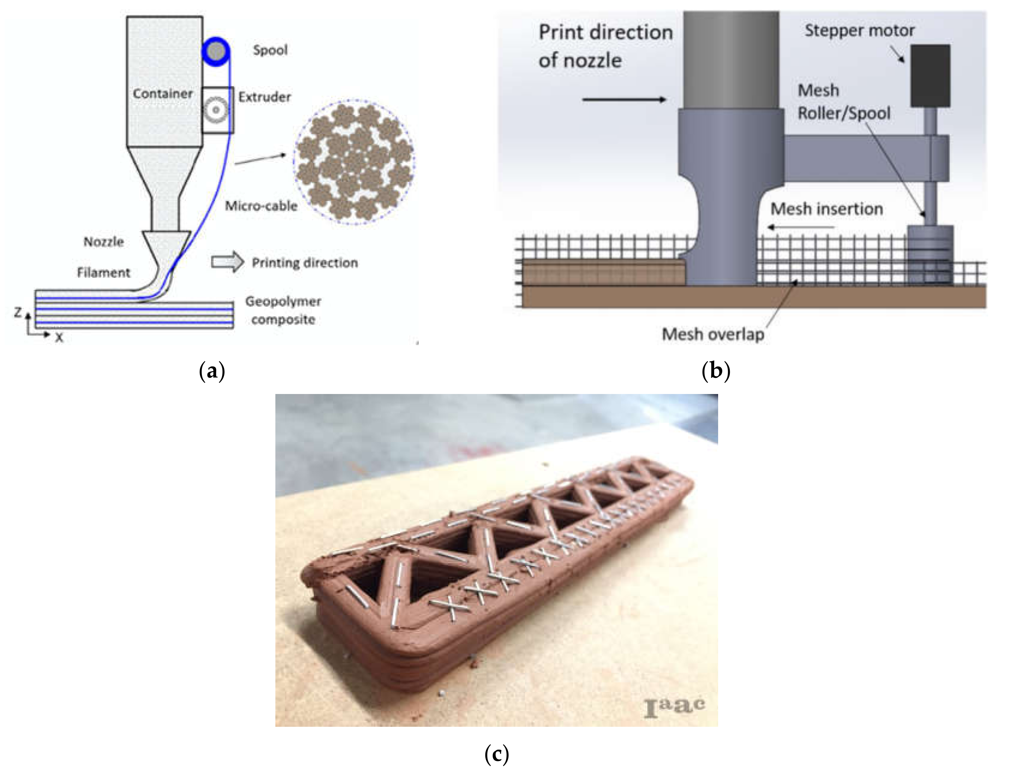
  • In-process reinforcement: Continuous reinforcement is placed as the material is extruded. Researchers confirmed the feasibility of simultaneously entraining steel cables to printed mixtures during the extrusion process [163,164,165,166] (Figure 14a). Despite improving mechanical capacities of printed structures, cable reinforcement fails to address the problem of weak interlayer bonding introduced by the printing process. To improve the bonding and enhance the overall performance, Marchment and Sanjayan [167] integrated mesh reinforcement within the printing process. A forked nozzle (similar to the nozzle in pre-installed reinforcement) is designed to allow the embedding of continuous reinforcing mesh in the middle of the printed material (Figure 14b). Geneidy et al. [168,169] further combined a printing nozzle with a stapler that can insert staple profiles into the printed materials, maximizing structural integrity (indicated in Figure 14c). All of those methods involve directly entraining reinforcement during printing using a highly automated printing system. The addition of fibers to mixtures is an alternative approach that has been explored widely. A high degree of fiber alignment along the printing direction can be introduced by the extrusion process (see Section 3.3.2 and Figure 9), improving the mechanical performance of the printed materials. Although these in-process reinforcement methods enable the highest degree of automation and design freedom, they might not provide the printed cementitious materials with the same level of tensile and compressive strength as pre-installed or post-installed methods (i.e., steel rebar provides a higher reinforcing level compared to the other reinforcing materials, such as cable, mesh, and fiber).
Among the reinforcing methods mentioned above, few of them (e.g., mesh and staple reinforcements) are considered effective in reinforcing in the interlayer direction, which is much more essential for 3D-printing. To maximize the mechanical performance of the printed elements, combining some of the reinforcement strategies for specific purposes may be an appropriate approach.

4. Mix Design

Table 1 summarizes the internal (mix design) and external (printing parameters, printing system, and curing conditions) factors along with experimental testing for the fresh and hardened properties mentioned in the above sections. The reader can refer to Section 2 and Section 3 for more details.
As seen in Table 1, mix design is an effective internal factor influencing both fresh and hardened properties of 3D-printed cementitious materials. To satisfy the mentioned requirements of the printable materials, a brief step-by-step mix design approach is proposed in Figure 15. Proportions of printable mixtures reported in literature could be used as a starting point. Generally, the basic principle of raw materials selection consists of high aggregate content (buildability, shrinkage, and cost control) and smooth particle grading (flowability and extrudability control). Since the size and geometry of printing nozzles limit the maximum particle size of raw materials, extrudability becomes the first parameter to be considered. The diameter ratio of 4.25 (see Section 2.2.2) can be adopted during raw material selection.
After designing an initial mixture, performance assessments of the mixture and modification procedures are conducted iteratively. A failure to fulfill the extrudability requirement can be due to a high content of aggregates or fibers. Adjusting paste volume or fiber content can be an option, and other alternative materials, such as mineral admixtures, should be considered to produce extrudable materials with designed strength. With sufficient extrudability, other fresh properties can be refined mainly based on the employment of chemical admixtures. Detailed discussions about the use of various chemical admixtures can be found in Reference [111]. Note that it is necessary to identify the printing scale (depending on the size of the designed structures), since it is highly related to the required open time, which controls the interlayer bonding, as well as the buildable performance (see Section 2). After the fresh properties are optimized, mechanical performance and shrinkage behavior need to be evaluated. Finally, a full-size printer (e.g., Figure 1) is used for further verification testing at a similar ambient temperature and humidity as the project of interest.

5. Perspectives

3D-printing technology for construction applications affords significant advantages over traditional casting methods. Successful development of the technology, however, requires interdisciplinary research to create suitable printing systems, design strategies, and printable materials. It is then necessary to model the complex relationships among the various variables associated with each of these areas, and between them and environmental variables like humidity and temperature. Regarding the printing system, it is crucial to consider aspects, such as degree of autonomy; ease of deployment and set up; design flexibility and complexity; and the dimension of the printing envelope. It is also necessary to identify appropriate pumping hose, printing nozzle, and other accessories that help the automatic installation of building elements like windows and doors.
With respect to design, there are two major aspects. The first is to understand which building forms are more amenable to 3D-printing, that is, which forms can be printed faster, with fewer supports and less reinforcement. The second aspect is related to printing path design, and the goal is to determine strategies to virtually decompose large buildings forms into smaller printable forms, slice them adequately into layers, and then into filaments that can be connected to each other, thereby defining the trajectory that the nozzle should traverse to physically recompose the form.
Research should also focus on the development of materials with adequate rheological properties, to guarantee adequate fresh and hardened properties. It is equally important to model the deformation of extruded materials to take this information into account in the design of the printing path to guarantee the accuracy of the printed forms.
Novel materials and corresponding printing systems are now under development for large-scale construction. Future research priorities in the area of 3D-printed cementitious materials include, but are not limited to:
  • Validation and standardization of testing methods, in particular, the quantitative assessment of the time history of material properties in the fresh age;
  • Development of effective reinforcing and curing solutions for different applications;
  • Analysis of long-term dimensional stability (i.e., shrinkage and creep) and durability;
  • Simulation modeling and analysis at multiscale level, including microscale cement hydration, mesoscale rheology, and macroscale mechanics;
  • Utilization of anisotropy introduced by the printing process to fabricate functionally graded cementitious materials by programmable anisotropic fabrication approach;
  • Development of durable and sustainable materials for construction-scale 3D-printing to reduce carbon footprint; and
  • Development of printable cementitious materials compatible with harsh environments for post-disaster housing reconstruction and planetary construction (considering resources, gravity, temperature, humidity, and radiation).

Author Contributions

Conceptualization, Z.L., M.H. and Z.W.; visualization, Z.L., M.H., Z.W. and N.A.; writing—original draft preparation, Z.L., M.H. and Z.W.; writing—review and editing, Z.L., M.H., Z.W., J.P., N.A., J.P.D., S.N., S.G.B., A.M.M. and A.R.; supervision, A.R. All authors have read and agreed to the published version of the manuscript.

Funding

This research work was supported by the Raymond A. Bowers Program for Excellence in Design and Construction of the Built Environment, Penn State; Autodesk, Inc.; and Gulf Concrete Technology.

Acknowledgments

The authors would like to thank the anonymous reviewers for their valuable comments and suggestions to improve the quality of the paper.

Conflicts of Interest

The authors declare no conflict of interest.

References

  1. ISO. Additive Manufacturing General Principles—Terminology; ISO/ASTM 52900:2015; ISO: Geneva, Switzerland, 2015. [Google Scholar]
  2. Wong, K.V.; Hernandez, A. A Review of Additive Manufacturing. ISRN Mech. Eng. 2012, 2012, 1–10. [Google Scholar] [CrossRef] [Green Version]
  3. Wegrzyn, T.F.; Golding, M.; Archer, R. Food Layered Manufacture: A new process for constructing solid foods. Trends Food Sci. Technol. 2012, 27, 66–72. [Google Scholar] [CrossRef]
  4. Guo, N.; Leu, M. Additive manufacturing: Technology, applications and research needs. Front. Mech. Eng. 2013, 8, 215–243. [Google Scholar] [CrossRef]
  5. Nematollahi, B.; Xia, M.; Sanjayan, J. Current Progress of 3D Concrete Printing Technologies. In Proceedings of the 34th International Symposium on Automation and Robotics in Construction, Taipei, Taiwan, 28 June–1 July 2017; pp. 260–267. [Google Scholar]
  6. Buswell, R.A.; Soar, R.; Gibb, A.; Thorpe, A. Freeform Construction: Mega-scale Rapid Manufacturing for construction. Autom. Constr. 2007, 16, 224–231. [Google Scholar] [CrossRef] [Green Version]
  7. Xia, M.; Sanjayan, J. Method of formulating geopolymer for 3D printing for construction applications. Mater. Des. 2016, 110, 382–390. [Google Scholar] [CrossRef]
  8. Sanjayan, J.; Nematollahi, B.; Xia, M.; Marchment, T. Effect of surface moisture on inter-layer strength of 3D printed concrete. Constr. Build. Mater. 2018, 172, 468–475. [Google Scholar] [CrossRef]
  9. Lowke, D.; Dini, E.; Perrot, A.; Weger, D.; Gehlen, C.; Dillenburger, B. Particle-bed 3D printing in concrete construction—Possibilities and challenges. Cem. Concr. Res. 2018, 112, 50–65. [Google Scholar] [CrossRef]
  10. Cesaretti, G.; Dini, E.; De Kestelier, X.; Colla, V.; Pambaguian, L. Building components for an outpost on the Lunar soil by means of a novel 3D printing technology. Acta Astronaut. 2014, 93, 430–450. [Google Scholar] [CrossRef]
  11. Gibbons, G.J.; Williams, R.; Purnell, P.; Farahi, E. 3D Printing of cement composites. Adv. Appl. Ceram. 2010, 109, 287–290. [Google Scholar] [CrossRef] [Green Version]
  12. Maier, A.-K.; Dezmirean, L.; Will, J.; Greil, P. Three-dimensional printing of flash-setting calcium aluminate cement. J. Mater. Sci. 2011, 46, 2947–2954. [Google Scholar] [CrossRef]
  13. Shakor, P.; Nejadi, S.; Paul, G.; Sanjayan, J. Dimensional accuracy, flowability, wettability, and porosity in inkjet 3DP for gypsum and cement mortar materials. Autom. Constr. 2020, 110, 102964. [Google Scholar] [CrossRef]
  14. Shakor, P.; Sanjayan, J.; Nazari, A.; Nejadi, S. Modified 3D printed powder to cement-based material and mechanical properties of cement scaffold used in 3D printing. Constr. Build. Mater. 2017, 138, 398–409. [Google Scholar] [CrossRef]
  15. Shakor, P.; Nejadi, S.; Paul, G.; Sanjayan, J.; Nazari, A. Mechanical Properties of Cement-Based Materials and Effect of Elevated Temperature on Three-Dimensional (3-D) Printed Mortar Specimens in Inkjet 3-D Printing. Aci Mater. J. 2019, 116, 55–67. [Google Scholar]
  16. Shakor, P.; Nejadi, S.; Paul, G. Investigation into the effect of delays between printed layers on the mechanical strength of inkjet 3DP mortar. Manuf. Lett. 2020, 23, 19–22. [Google Scholar] [CrossRef]
  17. Feng, P.; Meng, X.; Chen, J.-F.; Ye, L. Mechanical properties of structures 3D printed with cementitious powders. Constr. Build. Mater. 2015, 93, 486–497. [Google Scholar] [CrossRef] [Green Version]
  18. Feng, P.; Meng, X.; Zhang, H. Mechanical behavior of FRP sheets reinforced 3D elements printed with cementitious materials. Compos. Struct. 2015, 134, 331–342. [Google Scholar] [CrossRef]
  19. Alghamdi, H.; Neithalath, N. Synthesis and characterization of 3D-printable geopolymeric foams for thermally efficient building envelope materials. Cem. Concr. Compos. 2019, 104, 103377. [Google Scholar] [CrossRef]
  20. Xia, M.; Nematollahi, B.; Nazari, A.M. Printability, accuracy and strength of geopolymer made using powder-based 3D printing for construction applications. Autom. Constr. 2019, 101, 179–189. [Google Scholar] [CrossRef]
  21. Khoshnevis, B.; Hwang, D.; Yao, K.T.; Yeh, Z. Mega-scale fabrication by Contour Crafting. Int. J. Ind. Syst. Eng. 2006, 1, 301. [Google Scholar] [CrossRef] [Green Version]
  22. Khoshnevis, B.; Dutton, R. Innovative Rapid Prototyping Process Makes Large Sized, Smooth Surfaced Complex Shapes in a Wide Variety of Materials. Mater. Technol. 1998, 13, 53–56. [Google Scholar] [CrossRef]
  23. Khoshnevis, B.; Bukkapatnam, S.; Kwon, H.; Saito, J. Experimental investigation of contour crafting using ceramics materials. Rapid Prototyping J. 2001, 7, 32–42. [Google Scholar] [CrossRef]
  24. Lim, S.; Buswell, R.A.; Le, T.; Austin, S.; Gibb, A.; Thorpe, T. Developments in construction-scale additive manufacturing processes. Autom. Constr. 2012, 21, 262–268. [Google Scholar] [CrossRef] [Green Version]
  25. Lim, S.; Le, T.; Webster, J.; Buswell, R.; Austin, A.; Gibb, A.; Thorpe, T. Fabricating Construction Components Using Layered Manufacturing Technology. In Proceedings of the International Conference on Global Innovation in Construction, Loughborough, UK, 13–16 September 2009; pp. 512–520. [Google Scholar]
  26. Nerella, V.N.; Krause, M.; Näther, M.; Mechtcherine, V. Studying Printability of Fresh Concrete for Formwork Free Concrete On-Site 3D Printing Technology (Conprint3D). In Proceedings of the 25th Conference on Rheology of Building Materials, Regensburg, Germany, 2–3 March 2016. [Google Scholar]
  27. Hojati, M.; Nazarian, S.; Duarte, J.P.; Radlinska, A.; Ashrafi, N.; Craveiro, F.; Bilen, S. 3D Printing of Concrete: A Continuous Exploration of Mix Design and Printing Process. In Proceedings of the 42nd IAHS World Congress on Housing, Naples, Italy, 10–13 April 2018. [Google Scholar]
  28. Hojati, M.; Radlińska, A.; Nazarian, S.; Duarte, J.P.; Memari, A.M.; Meisel, N.; Bilén, S. Synthesis and 3D Printing of One-Part Geopolymer Mortar. In Proceedings of the 1st RILEM International Conference on Concrete and Digital Fabrication, Zurich, Switzerland, 10–12 September 2018. [Google Scholar]
  29. Hojati, M.; Radlinska, A.; Nazarian, S.; Duarte, J.; Memari, A.; Meisel, N.; Bilen, S. Design and 3D Printing of Two-Part Geopolymer Mortar. In Proceedings of the 1st RILEM International Conference on Concrete and Digital Fabrication, Zurich, Switzerland, 10–12 September 2018. [Google Scholar]
  30. Nazarian, S.; Duarte, J.; Bilen, S.; Memari, A.; Radlinska, A.; Meisel, N.; Hojati, M. Additive Manufacturing of Architectural Structures: An Interplay Between Materials, Systems, and Design. In Proceedings of the Conference on Automation Innovation in Construction (CIAC2019), Leiria, Portugal, 7–8 November 2019. [Google Scholar]
  31. Nazarian, S.; Duarte, J.; Bilén, S.; Memari, A.; Muthumanickam, N.K.; Watson, N.D.; Radlinska, A.; Ashrafi, N.; Hojati, M. An Overview of the Execution of 3D-Printed Subscale Habitat On Mars: A Case Study to Exemplify the Automated Construction Process. In Proceedings of the 5th Residential Building Design & Construction Conference, State College, PA, USA, 4–6 March 2020. [Google Scholar]
  32. Le, T.T.; Austin, S.; Lim, S.; Buswell, R.A.; Gibb, A.G.F.; Thorpe, T. Mix design and fresh properties for high-performance printing concrete. Mater. Struct. 2012, 45, 1221–1232. [Google Scholar] [CrossRef] [Green Version]
  33. Le, T.; Austin, S.; Lim, S.; Buswell, R.A.; Law, R.; Gibb, A.; Thorpe, T. Hardened properties of high-performance printing concrete. Cem. Concr. Res. 2012, 42, 558–566. [Google Scholar] [CrossRef] [Green Version]
  34. Flatt, R.J.; Wangler, T. Editorial for special issue on digital concrete. Cem. Concr. Res. 2018, 112, 1–4. [Google Scholar] [CrossRef]
  35. Hamidi, F.; Aslani, F. Additive manufacturing of cementitious composites: Materials, methods, potentials, and challenges. Constr. Build. Mater. 2019, 218, 582–609. [Google Scholar] [CrossRef]
  36. Ma, G.; Wang, L.; Ju, Y. State-of-the-art of 3D printing technology of cementitious material—An emerging technique for construction. Sci. China Ser. E Technol. Sci. 2017, 61, 475–495. [Google Scholar] [CrossRef]
  37. Ma, G.; Wang, L. A critical review of preparation design and workability measurement of concrete material for largescale 3D printing. Front. Struct. Civ. Eng. 2018, 12, 382–400. [Google Scholar] [CrossRef]
  38. Zhang, J.; Wang, J.; Dong, S.; Yu, X.; Han, B. A review of the current progress and application of 3D printed concrete. Compos. Part A Appl. Sci. Manuf. 2019, 125, 105533. [Google Scholar] [CrossRef]
  39. Lu, B.; Weng, Y.; Li, M.; Qian, Y.; Leong, K.F.; Tan, M.J.; Qian, S. A systematical review of 3D printable cementitious materials. Constr. Build. Mater. 2019, 207, 477–490. [Google Scholar] [CrossRef]
  40. Van der Zee, A.; de Vries, B.; Salet, T. From Rapid Prototyping to Automated Manufacturing. In Proceedings of the 32nd International Conference on Education and research in Computer Aided Architectural Design in Europe, Newcastle upon Tyne, UK, 10–12 September 2014; pp. 455–461. [Google Scholar]
  41. Van Zijl, G.P.A.G. Properties of 3D Printable Concrete. In Proceedings of the 2nd International Conference on Progress in Additive Manufacturing, Singapore, 16–19 May 2016; pp. 421–426. [Google Scholar]
  42. Panda, B.; Paul, S.C.; Tan, M.J. Anisotropic mechanical performance of 3D printed fiber reinforced sustainable construction material. Mater. Lett. 2017, 209, 146–149. [Google Scholar] [CrossRef]
  43. Panda, B.; Tan, M.J. Experimental study on mix proportion and fresh properties of fly ash based geopolymer for 3D concrete printing. Ceram. Int. 2018, 44, 10258–10265. [Google Scholar] [CrossRef]
  44. Malaeb, Z.; Hachem, H.; Tourbah, A.; Maalouf, T.; Zarwi, N.E.; Hamzeh, F. 3D Concrete Printing: Machine and Mix Design. Int. J. Civ. Eng. Technol. 2015, 6, 14–22. [Google Scholar]
  45. Tay, Y.W.D.; Panda, B.; Paul, S.C.; Tan, M.J.; Qian, S.Z.; Leong, K.F.; Chua, C.K. Processing and Properties of Construction Materials for 3D Printing. Mater. Sci. Forum 2016, 861, 177–181. [Google Scholar] [CrossRef]
  46. Ma, G.; Li, Z.; Wang, L. Printable properties of cementitious material containing copper tailings for extrusion based 3D printing. Constr. Build. Mater. 2018, 162, 613–627. [Google Scholar] [CrossRef]
  47. Khalil, N.; Aouad, G.; El Cheikh, K.; Rémond, S. Use of calcium sulfoaluminate cements for setting control of 3D-printing mortars. Constr. Build. Mater. 2017, 157, 382–391. [Google Scholar] [CrossRef]
  48. Zhang, Y.; Zhang, Y.; Liu, G.; Yang, Y.; Wu, M.; Pang, B. Fresh properties of a novel 3D printing concrete ink. Constr. Build. Mater. 2018, 174, 263–271. [Google Scholar] [CrossRef]
  49. Neville, A.M. Properties of Concrete; Pearson Education Limited: Harlow, UK, 1995. [Google Scholar]
  50. Tattersall, G.H. Workability and Quality Control of Concrete; E & FN Spon: London, UK, 1991. [Google Scholar]
  51. Monteiro, P.J.M.; Mehta, P.K. Concrete: Microstructure, Properties and Materials; McGraw-Hill Education: New York, NY, USA, 2014. [Google Scholar]
  52. Qian, Y.; De Schutter, G. Enhancing thixotropy of fresh cement pastes with nanoclay in presence of polycarboxylate ether superplasticizer (PCE). Cem. Concr. Res. 2018, 111, 15–22. [Google Scholar] [CrossRef]
  53. Roussel, N. Rheological requirements for printable concretes. Cem. Concr. Res. 2018, 112, 76–85. [Google Scholar] [CrossRef]
  54. Paul, S.C.; Tay, Y.W.D.; Panda, B.; Tan, M.J. Fresh and hardened properties of 3D printable cementitious materials for building and construction. Arch. Civ. Mech. Eng. 2018, 18, 311–319. [Google Scholar] [CrossRef]
  55. Shakor, P.; Nejadi, S.; Paul, G. A Study into the Effect of Different Nozzles Shapes and Fibre-Reinforcement in 3D Printed Mortar. Materials 2019, 12, 1708. [Google Scholar] [CrossRef] [PubMed] [Green Version]
  56. Kazemian, A.; Yuan, X.; Cochran, E.; Khoshnevis, B. Cementitious materials for construction-scale 3D printing: Laboratory testing of fresh printing mixture. Constr. Build. Mater. 2017, 145, 639–647. [Google Scholar] [CrossRef]
  57. Rushing, T.S.; Al-Chaar, G.; Eick, B.; Burroughs, J.; Shannon, J.; Barna, L.; Case, M. Investigation of concrete mixtures for additive construction. Rapid Prototyping J. 2017, 23, 74–80. [Google Scholar] [CrossRef]
  58. Soltan, D.G.; Li, V.C. A self-reinforced cementitious composite for building-scale 3D printing. Cem. Concr. Compos. 2018, 90, 1–13. [Google Scholar] [CrossRef]
  59. Sun, X.; Wang, Q.; Wang, H.; Chen, L. Influence of multi-walled nanotubes on the fresh and hardened properties of a 3D printing PVA mortar ink. Constr. Build. Mater. 2020, 247, 118590. [Google Scholar] [CrossRef]
  60. Zareiyan, B.; Khoshnevis, B. Effects of mixture ingredients on extrudability of concrete in Contour Crafting. Rapid Prototyping J. 2018, 24, 722–730. [Google Scholar] [CrossRef]
  61. Zhang, Y.; Zhang, Y.; She, W.; Yang, L.; Liu, G.; Yang, Y. Rheological and harden properties of the high-thixotropy 3D printing concrete. Constr. Build. Mater. 2019, 201, 278–285. [Google Scholar] [CrossRef]
  62. Shakor, P.; Renneberg, J.; Nejadi, S.; Paul, G. Optimisation of Different Concrete Mix Designs for 3D Printing by Utilizing 6Dof Industrial Robot. In Proceedings of the 34th International Symposium on Automation and Robotics in Construction, Taipei, Taiwan, 28 June–1 July 2017; pp. 268–275. [Google Scholar]
  63. Wallevik, J.E. Relationship between the Bingham parameters and slump. Cem. Concr. Res. 2006, 36, 1214–1221. [Google Scholar] [CrossRef]
  64. Uchikawa, H.; Sawaki, D.; Hanehara, S. Influence of kind and added timing of organic admixture on the composition, structure and property of fresh cement paste. Cem. Concr. Res. 1995, 25, 353–364. [Google Scholar] [CrossRef]
  65. Uchikawa, H.; Hanehara, S.; Sawaki, D. The role of steric repulsive force in the dispersion of cement particles in fresh paste prepared with organic admixture. Cem. Concr. Res. 1997, 27, 37–50. [Google Scholar] [CrossRef]
  66. Barfield, M.; Ghafoori, N. Air-entrained self-consolidating concrete: A study of admixture sources. Constr. Build. Mater. 2012, 26, 490–496. [Google Scholar] [CrossRef]
  67. Zain, M.; Safiuddin, M.; Yusof, K. A study on the properties of freshly mixed high performance concrete. Cem. Concr. Res. 1999, 29, 1427–1432. [Google Scholar] [CrossRef]
  68. Lorimer, P.; Omari, M.A.; Claisse, P.A. Workability of Cement Pastes. Aci Mater. J. 2001, 98, 476–482. [Google Scholar]
  69. Lee, S.H.; Kim, H.J.; Sakai, E.; Daimon, M. Effect of Particle Size Distribution of Fly Ash–Cement System On the Fluidity of Cement Pastes. Cem. Concr. Res. 2003, 3, 763–768. [Google Scholar] [CrossRef]
  70. Ramachandran, V.S. Concrete Admixtures Handbook: Properties, Science and Technology; William Andrew: Norwich, NY, USA, 1996. [Google Scholar]
  71. Yahia, A.; Tanimura, M.; Shimoyama, Y. Rheological properties of highly flowable mortar containing limestone filler-effect of powder content and W/C ratio. Cem. Concr. Res. 2005, 35, 532–539. [Google Scholar] [CrossRef]
  72. Uysal, M.; Yilmaz, K.; Ipek, M. The effect of mineral admixtures on mechanical properties, chloride ion permeability and impermeability of self-compacting concrete. Constr. Build. Mater. 2012, 27, 263–270. [Google Scholar] [CrossRef]
  73. Ferraris, C.F.; Obla, K.H.; Hill, R. The influence of mineral admixtures on the rheology of cement paste and concrete. Cem. Concr. Res. 2001, 31, 245–255. [Google Scholar] [CrossRef]
  74. Bayasi, M.Z.; Soroushian, P. Effect of Steel Fiber Reinforcement On Fresh Mix Properties of Concrete. Aci Mater. J. 1992, 89, 369–374. [Google Scholar]
  75. Grünewald, S.; Walraven, J.C. Parameter-study on the influence of steel fibers and coarse aggregate content on the fresh properties of self-compacting concrete. Cem. Concr. Res. 2001, 31, 1793–1798. [Google Scholar] [CrossRef]
  76. Şahmaran, M.; Yurtseven, A.; Yaman, I.O. Workability of hybrid fiber reinforced self-compacting concrete. Build. Environ. 2005, 40, 1672–1677. [Google Scholar] [CrossRef]
  77. Shakor, P.; Nejadi, S.; Sutjipto, S.; Paul, G.; Gowripalan, N. Effects of deposition velocity in the presence/absence of E6-glass fibre on extrusion-based 3D printed mortar. Addit. Manuf. 2020, 32, 101069. [Google Scholar] [CrossRef]
  78. Paul, S.C.; Van Zijl, G.P.A.G.; Tan, M.J.; Gibson, I. A review of 3D concrete printing systems and materials properties: Current status and future research prospects. Rapid Prototyping J. 2018, 24, 784–798. [Google Scholar] [CrossRef] [Green Version]
  79. Shakor, P.; Nejadi, S.; Paul, G.; Malek, S. Review of Emerging Additive Manufacturing Technologies in 3D Printing of Cementitious Materials in the Construction Industry. Front. Built Environ. 2019, 4, 85. [Google Scholar] [CrossRef] [Green Version]
  80. Rubio, M.; Sonebi, M.; Amziane, S. 3D Printing of Fibre Cement-Based Materials: Fresh and Rheological Performances. In Proceedings of the 2nd International Conference On Bio-Based Building Materials, Clermont-Ferrand, France, 21–23 June 2017. [Google Scholar]
  81. Barra Bizinotto, M.; Faleschini, F.; Jiménez Fernández, C.G.; Aponte Hernández, D. F Effects of chemical admixtures on the rheology of fresh recycled aggregate concretes. Constr. Build. Mater. 2017, 151, 353–362. [Google Scholar] [CrossRef]
  82. Hu, C.; De Larrard, F. The rheology of fresh high-performance concrete. Cem. Concr. Res. 1996, 26, 283–294. [Google Scholar] [CrossRef]
  83. Le, H.D.; Kadri, E.H.; Aggoun, S.; Vierendeels, J.; Troch, P.; De Schutter, G. Effect of lubrication layer on velocity profile of concrete in a pumping pipe. Mater. Struct. 2015, 48, 3991–4003. [Google Scholar] [CrossRef]
  84. Rahul, A.; Santhanam, M. Evaluating the printability of concretes containing lightweight coarse aggregates. Cem. Concr. Compos. 2020, 109, 103570. [Google Scholar] [CrossRef]
  85. Hambach, M.; Volkmer, D. Properties of 3D-printed fiber-reinforced Portland cement paste. Cem. Concr. Compos. 2017, 79, 62–70. [Google Scholar] [CrossRef]
  86. Perrot, A.; Rangeard, D.; Melinge, Y. Prediction of the Ram Extrusion Force of Cement-Based Materials. Appl. Rheol. 2014, 24, 34–40. [Google Scholar] [CrossRef]
  87. Perrot, A.; Lanos, C.; Estellé, P.; Mélinge, Y. Ram extrusion force for a frictional plastic material: Model prediction and application to cement paste. Rheol. Acta 2006, 45, 457–467. [Google Scholar] [CrossRef] [Green Version]
  88. Perrot, A.; Mélinge, Y.; Rangeard, D.; Micaelli, F.; Estellé, P.; Lanos, C.; Perrot, A. Use of ram extruder as a combined rheo-tribometer to study the behaviour of high yield stress fluids at low strain rate. Rheol. Acta 2012, 51, 743–754. [Google Scholar] [CrossRef] [Green Version]
  89. El Cheikh, K.; Rémond, S.; Khalil, N.; Aouad, G. Numerical and experimental studies of aggregate blocking in mortar extrusion. Constr. Build. Mater. 2017, 145, 452–463. [Google Scholar] [CrossRef]
  90. Ashrafi, N.; Duarte, J.P.; Nazarian, S.; Meisel, N.A. Evaluating the relationship between deposition and layer quality in large-scale additive manufacturing of concrete. Virtual Phys. Prototyping 2018, 14, 135–140. [Google Scholar] [CrossRef]
  91. Kruger, J.; Zeranka, S.; Van Zijl, G. 3D concrete printing: A lower bound analytical model for buildability performance quantification. Autom. Constr. 2019, 106, 102904. [Google Scholar] [CrossRef]
  92. Suiker, A.S.J. Mechanical performance of wall structures in 3D printing processes: Theory, design tools and experiments. Int. J. Mech. Sci. 2018, 137, 145–170. [Google Scholar] [CrossRef] [Green Version]
  93. Wolfs, R.J.M.; Bos, F.P.; Salet, T.A.M. Early age mechanical behaviour of 3D printed concrete: Numerical modelling and experimental testing. Cem. Concr. Res. 2018, 106, 103–116. [Google Scholar] [CrossRef]
  94. Wolfs, R.J.M.; Suiker, A.S.J. Structural failure during extrusion-based 3D printing processes. Int. J. Adv. Manuf. Technol. 2019, 104, 565–584. [Google Scholar] [CrossRef] [Green Version]
  95. Jayathilakage, R.; Rajeev, P.; Sanjayan, J. Yield stress criteria to assess the buildability of 3D concrete printing. Constr. Build. Mater. 2020, 240, 117989. [Google Scholar] [CrossRef]
  96. Wolfs, R.J.M.; Bos, F.P.; Salet, T.A.M. Triaxial compression testing on early age concrete for numerical analysis of 3D concrete printing. Cem. Concr. Compos. 2019, 104, 103344. [Google Scholar] [CrossRef]
  97. Austin, S.A.; Goodier, C.I.; Robins, P.J. Low-volume wet-process sprayed concrete: Pumping and spraying. Mater. Struct. 2005, 38, 229–237. [Google Scholar] [CrossRef] [Green Version]
  98. Panda, B.; Paul, S.C.; Hui, L.J.; Tay, Y.W.D.; Tan, M.J. Additive manufacturing of geopolymer for sustainable built environment. J. Clean. Prod. 2017, 167, 281–288. [Google Scholar] [CrossRef]
  99. Perrot, A.; Rangeard, D.; Pierre, A. Structural built-up of cement-based materials used for 3D-printing extrusion techniques. Mater. Struct. 2016, 49, 1213–1220. [Google Scholar] [CrossRef]
  100. Yuan, Q.; Li, Z.; Zhou, D.; Huang, T.; Huang, H.; Jiao, D.; Shi, C. A feasible method for measuring the buildability of fresh 3D printing mortar. Constr. Build. Mater. 2019, 227, 116600. [Google Scholar] [CrossRef]
  101. Tregger, N.; Pakula, M.E.; Shah, S.P. Influence of clays on the rheology of cement pastes. Cem. Concr. Res. 2010, 40, 384–391. [Google Scholar] [CrossRef]
  102. Casagrande, L.; Esposito, L.; Menna, C.; Asprone, D.; Auricchio, F. Effect of testing procedures on buildability properties of 3D-printable concrete. Constr. Build. Mater. 2020, 245, 118286. [Google Scholar] [CrossRef]
  103. Panda, B.; Lim, J.H.; Tan, M.J.; Hui, L.J. Mechanical properties and deformation behaviour of early age concrete in the context of digital construction. Compos. Part B Eng. 2019, 165, 563–571. [Google Scholar] [CrossRef]
  104. Barnes, H.A. Thixotropy—A review. J. Non Newton. Fluid Mech. 1997, 70, 1–33. [Google Scholar] [CrossRef]
  105. Mehta, P.; Aïtcin, P.-C. Principles Underlying Production of High-Performance Concrete. Cem. Concr. Aggreg. 1990, 12, 70. [Google Scholar] [CrossRef]
  106. Panda, B.; Paul, S.C.; Mohamed, N.A.N.; Tay, Y.W.D.; Tan, M.J. Measurement of tensile bond strength of 3D printed geopolymer mortar. Measurement 2018, 113, 108–116. [Google Scholar] [CrossRef]
  107. Gosselin, C.; Duballet, R.; Roux, P.; Gaudillière, N.; Dirrenberger, J.; Morel, P. Large-scale 3D printing of ultra-high performance concrete—A new processing route for architects and builders. Mater. Des. 2016, 100, 102–109. [Google Scholar] [CrossRef] [Green Version]
  108. Roussel, N. A thixotropy model for fresh fluid concretes: Theory, validation and applications. Cem. Concr. Res. 2006, 36, 1797–1806. [Google Scholar] [CrossRef]
  109. Roussel, N. Steady and transient flow behaviour of fresh cement pastes. Cem. Concr. Res. 2005, 35, 1656–1664. [Google Scholar] [CrossRef]
  110. Roussel, N.; Ovarlez, G.; Garrault, S.; Brumaud, C. The origins of thixotropy of fresh cement pastes. Cem. Concr. Res. 2012, 42, 148–157. [Google Scholar] [CrossRef]
  111. Marchon, D.; Kawashima, S.; Bessaies-Bey, H.; Mantellato, S.; Ng, S. Hydration and rheology control of concrete for digital fabrication: Potential admixtures and cement chemistry. Cem. Concr. Res. 2018, 112, 96–110. [Google Scholar] [CrossRef]
  112. Roussel, N.; Bessaies-Bey, H.; Kawashima, S.; Marchon, D.; Vasilic, K.; Wolfs, R. Recent advances on yield stress and elasticity of fresh cement-based materials. Cem. Concr. Res. 2019, 124, 105798. [Google Scholar] [CrossRef]
  113. Kim, J.H.; Beacraft, M.; Shah, S.P. Effect of mineral admixtures on formwork pressure of self-consolidating concrete. Cem. Concr. Compos. 2010, 32, 665–671. [Google Scholar] [CrossRef]
  114. Kuder, K.G.; Shah, S.P. Rheology of Extruded Cement-Based Materials. Aci Mater. J. 2007, 104, 283–290. [Google Scholar]
  115. Voigt, T.; Mbele, J.-J.; Wang, K.; Shah, S.P. Using Fly Ash, Clay, and Fibers for Simultaneous Improvement of Concrete Green Strength and Consolidatability for Slip-Form Pavement. J. Mater. Civ. Eng. 2010, 22, 196–206. [Google Scholar] [CrossRef]
  116. Bos, F.P.; Ahmed, Z.Y.; Wolfs, R.J.M.; Salet, T.A.M. 3D Printing Concrete with Reinforcement. In Proceedings of the 2017 fib Symposium High Tech Concrete: Where Technology and Engineering Meet, Maastricht, The Netherlands, 12–14 June 2017; pp. 2484–2493. [Google Scholar]
  117. Zhu, J.; Zhang, T.; Faried, M.; Wengang, C. 3D Printing Cement Based Ink, and It’s Application within the Construction Industry. In Proceedings of the International Conference on Advances in Sustainable Construction Materials & Civil Engineering Systems, Sharjah, UAE, 18–20 April 2017. [Google Scholar]
  118. Ma, G.; Li, Z.; Wang, L.; Wang, F.; Sanjayan, J. Mechanical anisotropy of aligned fiber reinforced composite for extrusion-based 3D printing. Constr. Build. Mater. 2019, 202, 770–783. [Google Scholar] [CrossRef]
  119. Nerella, V.N.; Hempel, S.; Mechtcherine, V. Effects of layer-interface properties on mechanical performance of concrete elements produced by extrusion-based 3D-printing. Constr. Build. Mater. 2019, 205, 586–601. [Google Scholar] [CrossRef]
  120. Wolfs, R.J.M.; Bos, F.P.; Salet, T.A.M. Hardened properties of 3D printed concrete: The influence of process parameters on interlayer adhesion. Cem. Concr. Res. 2019, 119, 132–140. [Google Scholar] [CrossRef]
  121. Rahul, A.; Santhanam, M.; Meena, H.; Ghani, Z. Mechanical characterization of 3D printable concrete. Constr. Build. Mater. 2019, 227, 116710. [Google Scholar] [CrossRef]
  122. Asprone, D.; Auricchio, F.; Menna, C.; Mercuri, V. 3D printing of reinforced concrete elements: Technology and design approach. Constr. Build. Mater. 2018, 165, 218–231. [Google Scholar] [CrossRef]
  123. Ma, G.; Salman, N.M.; Wang, L.; Wang, F. A novel additive mortar leveraging internal curing for enhancing interlayer bonding of cementitious composite for 3D printing. Constr. Build. Mater. 2020, 244, 118305. [Google Scholar] [CrossRef]
  124. Wang, L.; Tian, Z.; Ma, G.; Zhang, M. Interlayer bonding improvement of 3D printed concrete with polymer modified mortar: Experiments and molecular dynamics studies. Cem. Concr. Compos. 2020, 110, 103571. [Google Scholar] [CrossRef]
  125. Zareiyan, B.; Khoshnevis, B. Interlayer adhesion and strength of structures in Contour Crafting—Effects of aggregate size, extrusion rate, and layer thickness. Autom. Constr. 2017, 81, 112–121. [Google Scholar] [CrossRef]
  126. Zareiyan, B.; Khoshnevis, B. Effects of interlocking on interlayer adhesion and strength of structures in 3D printing of concrete. Autom. Constr. 2017, 83, 212–221. [Google Scholar] [CrossRef]
  127. Al-Qutaifi, S.; Nazari, A.; Bagheri, A. Mechanical properties of layered geopolymer structures applicable in concrete 3D-printing. Constr. Build. Mater. 2018, 176, 690–699. [Google Scholar] [CrossRef]
  128. Zareiyan, B.; Khoshnevis, B. Effects of mixture ingredients on interlayer adhesion of concrete in Contour Crafting. Rapid Prototyping J. 2018, 24, 584–592. [Google Scholar] [CrossRef]
  129. Hosseini, E.; Zakertabrizi, M.; Korayem, A.H.; Xu, G. A novel method to enhance the interlayer bonding of 3D printing concrete: An experimental and computational investigation. Cem. Concr. Compos. 2019, 99, 112–119. [Google Scholar] [CrossRef]
  130. Panda, B.; Unluer, C.; Tan, M.J. Extrusion and rheology characterization of geopolymer nanocomposites used in 3D printing. Compos. Part B Eng. 2019, 176, 107290. [Google Scholar] [CrossRef]
  131. Austin, S.; Robins, P.J.; Goodier, C. The performance of hardened wet-process sprayed mortars. Mag. Concr. Res. 2000, 52, 195–208. [Google Scholar] [CrossRef]
  132. Stang, H.; Li, V.C. Extrusion of Ecc-Material. In Proceedings of the 3rd International RILEM Workshop on High Performance Fiber Reinforced Cement Composites, Mainz, Germany, 16–19 May 1999; pp. 203–212. [Google Scholar]
  133. Lakes, R. Materials with structural hierarchy. Nature 1993, 361, 511–515. [Google Scholar] [CrossRef]
  134. Fratzl, P.; Weinkamer, R. Nature’s hierarchical materials. Prog. Mater. Sci. 2007, 52, 1263–1334. [Google Scholar] [CrossRef] [Green Version]
  135. Meyers, M.A.; Chen, P.-Y.; Lin, A.Y.-M.; Seki, Y. Biological materials: Structure and mechanical properties. Prog. Mater. Sci. 2008, 53, 1–206. [Google Scholar] [CrossRef] [Green Version]
  136. De Koker, D.; Van Zijl, G. Extrusion of Engineered Cement-Based Composite Material. In Proceedings of the 6th RILEM Symposium on Fiber-Reinforced Concrete (FRC)-BEFIB, Verenna, Italy, 20–22 September 2004; pp. 1301–1310. [Google Scholar]
  137. Rossi, P.; Harrouche, N. Mix design and mechanical behaviour of some steel-fibre-reinforced concretes used in reinforced concrete structures. Mater. Struct. 1990, 23, 256–266. [Google Scholar] [CrossRef]
  138. Uygunoğlu, T. Effect of fiber type and content on bleeding of steel fiber reinforced concrete. Constr. Build. Mater. 2011, 25, 766–772. [Google Scholar] [CrossRef]
  139. Ma, G.; Zhang, J.; Wang, L.; Li, Z.; Sun, J. Mechanical characterization of 3D printed anisotropic cementitious material by the electromechanical transducer. Smart Mater. Struct. 2018, 27, 075036. [Google Scholar] [CrossRef]
  140. Compton, B.G.; Lewis, J.A. 3D-Printing of Lightweight Cellular Composites. Adv. Mater. 2014, 26, 5930–5935. [Google Scholar] [CrossRef]
  141. Hambach, M.; Möller, H.; Neumann, T.; Volkmer, D. Portland cement paste with aligned carbon fibers exhibiting exceptionally high flexural strength (>100 MPa). Cem. Concr. Res. 2016, 89, 80–86. [Google Scholar] [CrossRef]
  142. Austin, S.; Robins, P.; Pan, Y. Tensile bond testing of concrete repairs. Mater. Struct. 1995, 28, 249–259. [Google Scholar] [CrossRef]
  143. Austin, S.; Robins, P.; Pan, Y. Shear bond testing of concrete repairs. Cem. Concr. Res. 1999, 29, 1067–1076. [Google Scholar] [CrossRef]
  144. Tschegg, E.K.; Ingruber, M.; Surberg, C.H.; Munger, F. Factors Influencing Fracture Behavior of Old-New Concrete Bonds. Aci Mater. J. 2000, 97, 447–453. [Google Scholar]
  145. Júlio, E.N.B.S.; Branco, F.A.B.; Silva, V.D. Concrete-to-concrete bond strength. Influence of the roughness of the substrate surface. Constr. Build. Mater. 2004, 18, 675–681. [Google Scholar] [CrossRef] [Green Version]
  146. Lee, M.-G.; Wang, Y.-C.; Chiu, C.-T. A preliminary study of reactive powder concrete as a new repair material. Constr. Build. Mater. 2007, 21, 182–189. [Google Scholar] [CrossRef]
  147. Austin, S.; Robins, P.J. Development of patch test to study behaviour of shallow concrete patch repairs. Mag. Concr. Res. 1993, 45, 221–229. [Google Scholar] [CrossRef]
  148. Momayez, A.; Ehsani, M.; Ramezanianpour, A.; Rajaie, H. Comparison of methods for evaluating bond strength between concrete substrate and repair materials. Cem. Concr. Res. 2005, 35, 748–757. [Google Scholar] [CrossRef]
  149. Robins, P.J.; Austin, S. A unified failure envelope from the evaluation of concrete repair bond tests. Mag. Concr. Res. 1995, 47, 57–68. [Google Scholar] [CrossRef]
  150. Espeche, A.D.; León, J. Estimation of bond strength envelopes for old-to-new concrete interfaces based on a cylinder splitting test. Constr. Build. Mater. 2011, 25, 1222–1235. [Google Scholar] [CrossRef]
  151. Beushausen, H.; Alexander, M.G. Bond strength development between concretes of different ages. Mag. Concr. Res. 2008, 60, 65–74. [Google Scholar] [CrossRef]
  152. Tay, Y.W.D.; Ting, G.H.A.; Qian, Y.; Panda, B.; He, L.; Tan, M.J. Time gap effect on bond strength of 3D-printed concrete. Virtual Phys. Prototyping 2018, 14, 1–10. [Google Scholar] [CrossRef]
  153. Keita, E.; Bessaies-Bey, H.; Zuo, W.; Belin, P.; Roussel, N. Weak bond strength between successive layers in extrusion-based additive manufacturing: Measurement and physical origin. Cem. Concr. Res. 2019, 123, 105787. [Google Scholar] [CrossRef]
  154. Bos, F.; Wolfs, R.; Ahmed, Z.; Salet, T. Additive manufacturing of concrete in construction: Potentials and challenges of 3D concrete printing. Virtual Phys. Prototyping 2016, 11, 209–225. [Google Scholar] [CrossRef] [Green Version]
  155. Bissonnette, B.; Pierre, P.; Pigeon, M. Influence of key parameters on drying shrinkage of cementitious materials. Cem. Concr. Res. 1999, 29, 1655–1662. [Google Scholar] [CrossRef]
  156. Ma, B.-G.; Wen, X.-D.; Wang, M.-Y.; Yan, J.-J.; Xiao-Jian, G. Drying Shrinkage of Cement-Based Materials Under Conditions of Constant Temperature and Varying Humidity. J. China Univ. Min. Technol. 2007, 17, 428–431. [Google Scholar] [CrossRef]
  157. Baroghel-Bouny, V.; Mainguy, M.; Lassabatere, T.; Coussy, O. Characterization and identification of equilibrium and transfer moisture properties for ordinary and high-performance cementitious materials. Cem. Concr. Res. 1999, 29, 1225–1238. [Google Scholar] [CrossRef]
  158. Graham, M.D. The sharkskin instability of polymer melt flows. Chaos Interdiscip. J. Nonlinear Sci. 1999, 9, 154–163. [Google Scholar] [CrossRef]
  159. TV, N.C. World’s First 3D-Printed House that Can Withstand 8.0-Magnitude Quake. 2020. Available online: https://www.youtube.com/watch?v=OloOc21_u80 (accessed on 17 June 2020).
  160. Wu, P.; Wang, J.; Wang, X. A critical review of the use of 3-D printing in the construction industry. Autom. Constr. 2016, 68, 21–31. [Google Scholar] [CrossRef] [Green Version]
  161. Cor, A. Apis Cor Homepage. 2020. Available online: https://www.apis-cor.com/> (accessed on 17 June 2020).
  162. Salet, T.; Ahmed, Z.Y.; Bos, F.P.; Laagland, H.L.M. Design of a 3D printed concrete bridge by testing. Virtual Phys. Prototying. 2018, 13, 222–236. [Google Scholar] [CrossRef] [Green Version]
  163. Bos, F.P.; Ahmed, Z.Y.; Jutinov, E.R.; Salet, T.A.M. Experimental Exploration of Metal Cable as Reinforcement in 3D Printed Concrete. Materials 2017, 10, 1314. [Google Scholar] [CrossRef] [PubMed] [Green Version]
  164. Li, Z.; Wang, L.; Ma, G.; Wang, L. Mechanical improvement of continuous steel microcable reinforced geopolymer composites for 3D printing subjected to different loading conditions. Compos. Part B Eng. 2020, 187, 107796. [Google Scholar] [CrossRef]
  165. Ma, G.; Li, Z.; Wang, L.; Bai, G. Micro-cable reinforced geopolymer composite for extrusion-based 3D printing. Mater. Lett. 2019, 235, 144–147. [Google Scholar] [CrossRef]
  166. Lim, J.H.; Panda, B.; Pham, Q.-C. Improving flexural characteristics of 3D printed geopolymer composites with in-process steel cable reinforcement. Constr. Build. Mater. 2018, 178, 32–41. [Google Scholar] [CrossRef]
  167. Marchment, T.; Sanjayan, J. Mesh reinforcing method for 3D Concrete Printing. Autom. Constr. 2020, 109, 102992. [Google Scholar] [CrossRef]
  168. Geneidy, O.; Kumarji, S.; Dubor, A.; Sollazzo, A.; Chadha, K.; Krenmueller, R.; Bettucchi, E.; Lara, S. IAAC Simultaneous Reinforcement of Concrete while 3D Printing. 2019. Available online: http://www.iaacblog.com/programs/sim-reinforcement-concrete/ (accessed on 17 June 2020).
  169. Geneidy, O.; Kumarji, S.; Dubor, A.; Sollazzo, A. Simultaneous Reinforcement of Concrete while 3D Printing. In Proceedings of the 2nd RILEM International Conference on Concrete and Digital Fabrication, Eindhoven, The Netherlands, 6–9 July 2020; pp. 895–905. [Google Scholar]
Figure 1. Schematic of the extrusion-based 3D-printing setup: (1) computer for printing path (or tool path) design; (2) robot controller; (3) 6-axis robotic arm; (4) storage container for raw materials (e.g., cement and aggregates); (5) dry mixer; (6) wet mixer and pump; (7) pumping hose; (8) printing nozzle; and (9) printed specimen.
Sustainability 12 05628 g001
Figure 2. The 3D-printed structures from the PennStateDen@Mars team: (a) dome structure; (b) water reservoir; and (c) one-third-scale habitat.
Sustainability 12 05628 g002
Figure 3. Schematic illustration of vertical and horizontal deformation of filaments deposited through a circular nozzle: (a) theoretical and (b) practical geometries.
Sustainability 12 05628 g003
Figure 4. Evolution of yield stress of printable cementitious materials. The printing direction is schematically represented from right to left, with shades of grey indicating the age of the material. Note that the evolution during mixing is not included in this figure. (Adapted from Reference [111].)
Sustainability 12 05628 g004
Figure 5. Linear voids between filaments (namely inter-filament voids) in (a) transverse and (b) side view.
Sustainability 12 05628 g005
Figure 6. Print quality of 3D-printed cylinders with different printing speed: (a) low nozzle travel speed (poor printing, dense but not neat), (b) high nozzle travel speed (poor printing, neat but porous), and (c) well-adjusted nozzle travel speed (good printing, dense and neat), for a given material extrusion rate.
Sustainability 12 05628 g006
Figure 7. Testing directions for compressive strength test of printed cube specimens: (a) perpendicular, (b) longitudinal, and (c) lateral to the layer orientation. Note that a coordinate system XYZ is described where the directions of the X- and Z-axis are parallel to the printing path (dashed lines) and the gravitational direction (the height during the printing process), respectively. Printed layers locate in the X-Y plane.
Sustainability 12 05628 g007
Figure 8. Testing directions for flexural strength test of printed prism specimens: (a) and (b) perpendicular, (c) and (d) longitudinal, (e) and (f) lateral to the layer orientation. The coordinate system XYZ is the same as that in Figure 7.
Sustainability 12 05628 g008aSustainability 12 05628 g008b
Figure 9. Schematic illustration of fiber alignment within the printing nozzle during 3D-printing process.
Sustainability 12 05628 g009
Figure 10. Schematic illustration of interlayer bonding mechanism. (Adapted from Reference [152].) Interface material can be considered as a thin film of layer (present in the surface of fresh material), which serves as a lubrication layer in pumping hoses before extrusion and determines tensile bond strength between layers after extrusion [106].
Sustainability 12 05628 g010
Figure 11. (a) Top view and (b) close-up view of visible crack formation (attributed to plastic shrinkage caused by a high water evaporation rate near the surface) in a 3D-printed water reservoir.
Sustainability 12 05628 g011
Figure 12. Infrared thermographic images of a 3D-printed cylinder with metakaolin-based geopolymer: (a) lower layers and (b) upper layers.
Sustainability 12 05628 g012
Figure 13. Pre-installed reinforcement: (a) schematic representation and (b) a photograph. (Reproduced from Reference [167], with permission from Elsevier.)
Sustainability 12 05628 g013
Figure 14. In-process reinforcement with (a) steel cables, (b) mesh, and (c) staples. (Reproduced from References [165,167,168], with permission from Elsevier and the Institute for Advanced Architecture of Catalonia (IAAC).)
Sustainability 12 05628 g014
Figure 15. Mix design procedure for 3D-printable cementitious materials. (Adapted from Reference [36].)
Sustainability 12 05628 g015
Table 1. Summary of the experimental testing and effective factors for fresh and hardened properties.
Properties Effective FactorsExperimental Testing
InternalExternal
Mix Design 1Printing Parameters 2Printing System 3Curing Condition 4
FreshFlowabilityX 5- 6X-
ExtrudabilityXXX-
  • Assessment of printing distance without disruption [32,44,47]
  • Manual extrusion with qualitative rating [47,57,80]
  • Rheometer test [43]
BuildabilityXXX-
  • Direct measurement of the layer height or number of layers with minimum deformation [32,44,47,48,59]
  • Indirect measurements: vertical deformation under load [43,55,56,62,98,100], green strength [48,84,93,102,103], and rheological properties [48,99]
Open TimeX-XX
  • Direct measurement of the time period in which the materials could be extruded without disruption [46,56]
  • Indirect measurements: slump flow test [32] or rheometer test after specific time intervals [32,43,98,106]
HardenedDensityXX--
  • Density and void measurements [33]
  • Density and helium porosity measurements [85]
Compressive StrengthXXXX
  • Cube specimens in three [33,42,54,61,98] and two loading directions [120]
  • Prism specimens in three [8] and two loading directions [26,117]
  • Cylinder specimens [33]
Flexural StrengthXXXX
Tensile Bond StrengthXXXX
Shrinkage and CrackingXXXX
  • Prism specimens in three curing conditions [33]
1 Mix design includes the type and content of chemical admixtures (water-reducing, set-controlling, air-entraining, and bonding agents), mineral admixtures (e.g., fly ash, silica fume, slag, and clay), and reinforcing fibers. 2 Printing parameters include printing path, printing speed, printing time gap. 3 Printing system includes pump pressure, pumping distance, size and geometry of the pumping hose and the printing nozzle, and the attached trowels. 4 Curing conditions include temperature and relative humidity. 5 “X” denotes that there is a relationship between the factor and the property of interest. 6 “-” denotes that the factor has little or no influence on the property.

