Article

Performance of an Adsorptive Heat-Moisture Regenerator Based on Silica Gel–Sodium Sulphate

by
Elena Belyanovskaya
1,*,
Miroslav Rimár
2,
Roman D. Lytovchenko
1,
Miroslav Variny
3,*,
Kostyantyn M. Sukhyy
1,
Oleksandr O. Yeromin
4,
Mikhailo P. Sykhyy
1,
Elena M. Prokopenko
4,
Irina V. Sukha
5,
Mikhailo V. Gubinskyi
6 and
Ján Kizek
2
1
Department of Power Engineering, State Higher Education Institution, Ukrainian State University of Chemical Technology, Gagarine av. 8, 49005 Dnipro, Ukraine
2
Department of Process Engineering, Faculty of Manufacturing Technologies of the Technical University of Košice with a seat in Prešov, Technical University of Košice, Štúrova 31, 080 01 Prešov, Slovakia
3
Department of Chemical and Biochemical Engineering, Faculty of Chemical and Food Technology, Slovak University of Technology in Bratislava, Radlinského 9, 812 37 Bratislava, Slovakia
4
Department of Ecology, Heat Transfer and Labour Protection, National Metallurgical Academy of Ukraine, Gagarine av. 4, 49600 Dnipro, Ukraine
5
Department of Natural and Synthetic polymers, Fast and Food products, State Higher Education Institution, Ukrainian State University of Chemical Technology, Gagarine av. 8, 49005 Dnipro, Ukraine
6
Department of Industrial Power System, National Metallurgical Academy of Ukraine, Gagarine av. 4, 49600 Dnipro, Ukraine
*
Authors to whom correspondence should be addressed.
Sustainability 2020, 12(14), 5611; https://doi.org/10.3390/su12145611
Submission received: 4 May 2020 / Revised: 3 July 2020 / Accepted: 6 July 2020 / Published: 13 July 2020

Abstract

:
The performance of an adsorptive heat-moisture regenerator based on a silica gel–sodium sulphate composite adsorbent was studied. The correlation between the adsorbent composition and structural characteristics of the laboratory-scale device was investigated. An algorithm for the calculation of the efficiency factors of the adsorptive regenerator was further developed. The suggested algorithm calculates the operational parameters, including the temperatures, humidities and volumetric flows of internal and external air, and estimates the regenerator’s performance via temperature and moisture efficiency factors, total adsorption and time needed to achieve maximum adsorption, air pressure loss and fan power input. The validity of the calculation results obtained using the proposed algorithm was confirmed experimentally. Temperature efficiency factor, air pressure loss and fan power consumption are crucial parameters for the estimation of the optimal operating regime of an adsorptive heat-moisture regenerator. The correlation between meteorological conditions and efficiency factors was assessed and applied in a simulation of residential house-scale air conditioning unit operation. Maximal values of temperature efficiency factor were found at internal and external air temperatures of 15 to 20 °C and −5 to 0 °C, respectively. Moisture efficiency factors were observed to reach their maximum at the absolute humidities of external and internal air of 4.0 to 5.0 g/m3 and 2.75 to 3.0 g/m3, respectively. The fan power consumption of the adsorptive heat-moisture regenerator was found to be comparable to or even lower than that of commercial air conditioning units used in comparably voluminous interiors.

1. Introduction

The monotonic growth of energy consumption is one of the crucial challenges for the modern power industry. Primary energy consumption is predicted to rise by 48% by 2040 [1,2]. This underlines the need to develop new methods, materials and technologies for energy saving in buildings and industrial processes. Carbon dioxide levels are known to increase in the internal air of residential areas, which requires intermittent aeration and leads to increasing inputs for heat supply and ventilation [3,4]. Inputs for inflowing air heating have become the most serious contributor to thermal load on the heat supply side. Another requirement for ventilation systems is to maintain an acceptable humidity level according to sanitary regulations and rules [5].
Generally, these problems are solved by cooling air to temperatures below dew point and then heating it up to comfortable temperatures. Such devices, i.e., compression cooling machines, account for significant energy consumption during air conditioning [6,7], an issue that becomes even more pressing with the current problem of climate change [8]. The most easily realised engineering solutions to decrease the associated energy consumption are recuperative and regenerative heat exchangers [9,10]. These devices are not only suitable for central heating systems based on fossil fuels but also for solar heating systems used as a support for traditional fuel combustion systems. However, operating recuperative heat exchangers is complicated due to the significant amount of moisture in air ducts, which results in the formation of ice at the cold end of the heat exchanger and blocks its operation. Regenerative devices, where the warm exhaust air heats the cold incoming air, are more promising. Nevertheless, such units are generally based on sensible heat storage materials. Their operation thus affects only the relative humidity and does not result in a change in absolute humidity.
An alternative method is the adsorptive regeneration of heat and moisture, e.g., the Ventireg technology developed by Aristov et al. [11,12]. However, there is still a gap in the overall performance between the laboratory prototype and commercial applications. Apparently, this results from the low quality of the adsorbents used. Conventional adsorbents such as silica gels and zeolites can be used for air dewatering [11,13] in a fixed or fluidised bed mode [14] as well as in a desiccant wheel system [15,16].
More promising adsorbents are composites of the ‘salt inside porous matrix’ type [17], which have good operating characteristics in the storage and conversion of heat energy due to their high adsorptive capacity and heat adsorption [11,18]. The most promising of them are materials obtained using the sol–gel method [19]. Other intensely studied adsorbents include various composite materials [20,21,22] containing plastics, metals or even pulp. They can be further integrated with membrane-based systems [21,23] to improve their performance and used with various air conditioning unit layouts including solar collectors [24] and heat pumps [25].
Another obstacle to the commercialisation of adsorptive regenerators is the absence of algorithms for the estimation of integral operating parameters of the device or unit and for the evaluation of its design and performance in the conditions of typical ventilation systems considering all stages of exploitation. Even though adsorptive heat conversion devices operate in at least a two-stage mode, mathematical models are mostly designed for one stage only, i.e., adsorption [26,27]. Gaeini et al. [26] experimentally studied a water-13X zeolite-packed bed 51 L reactor for long-term energy storage and developed and tested a non-isothermal non-adiabatic reactor model. Gas flow rate and kinetic parameters were subjected to sensitivity analysis, revealing that slower adsorption led to a decrease in optimal air flow velocity. Intini et al. [28] investigated the influence of several process parameters on the energy performance of a desiccant wheel and identified the key process and design variables affecting it. The highest moisture removal and heat efficiency factors together with the lowest power consumption were found at identical stream inlet velocity conditions, while optimal wheel revolutions depended strongly on both air stream conditions and inlet velocities. Rafique et al. [29] performed a computational parametric study on a liquid desiccant wheel system, testing the dependence of its coefficient of performance on ambient air conditions. The studied system reached thermal coefficient of performance (COP) values of 0.3 to 0.6, while ambient humidity increase negatively affected all performance parameters. Mathematical modelling of a solid desiccant-based air conditioning system in a family house by Narayanan et al. [30] in the TRNSYS (TRaNsient SYStem simulation software) model showed the potential of this system to provide thermal comfort across a wide range of ambient air conditions in Australia. Thermal COP values of up to 0.4 were reached, while electric COP (thermal load divided by power consumption) values of almost 5 were obtained in a warm arid climate, which is a value close to the 4.6 reported in [29] for the Saudi Arabian climate. The proposed air conditioning unit was able to ensure thermal and humidity comfort over 90% of the time in an arid climate, whereas only 50% to 60% comfort time share was experienced in a warm humid climate. A solar-based heat pump-assisted system was modelled by Luo et al. [31] in Taiwan, and it was found to be suitable for application in such a warm and humid climate; the results were corroborated by Ukai et al. [32] who also incorporated the effect of optimised system regulation.
The above studies reveal that the key parameters affecting an adsorbent-filled air conditioning unit’s design and performance include both ambient and indoor conditions (temperature, humidity), as well as structural properties and physico-chemical parameters of the adsorbent used. The most important operation variables affecting the unit’s performance comprise flow velocities, temperature and humidity setpoints, and rotational speed (desiccant wheels). Electric energy consumption can be optimised by means of the adsorbent layer thickness, particle size and porosity as well as the rotational speed adjustment if rotating equipment is employed. While all these optimisation aspects were examined and verified in multiple studies, further model development supported by suitable experiments is required.
The performed literature review demonstrates that further experimental and computational studies on adsorbent-based air conditioning systems are needed as both their design and optimal operation are complex functions of adsorbent properties, air properties and their hourly and daily changes, anticipated working regime, media flow velocities etc. The mathematical model proposed in our earlier work [19] allows the estimation of the efficiency of an adsorptive heat-moisture regenerator only through the temperature efficiency factor. The energy performance of heat-moisture regenerators is, however, characterised by two efficiency factors, i.e., coefficients of heat and moisture regeneration, as well as by fan power consumption. Therefore, the present work is focused on the combined temperature-humidity-power input performance characteristics of an adsorptive heat-moisture regenerator based on silica gel–sodium sulphate composite with the aims of increasing its efficiency and decreasing its energy consumption, thus contributing to more sustainable and greener air conditioning units.
This paper includes an experimental part consisting of a description and short operational summary of the laboratory heat-moisture regenerator. The subsequent operational data evaluation assessment includes a complex mathematical model comprising the evaluation of two key efficiency factors (temperature and moisture efficiency factors) and the estimation of regenerator power consumption. Relevant data and observed trends in temperature and moisture efficiency factors as well as in air pressure loss and regenerator fan power consumption are shown and discussed in the Results and Discussion, resulting in recommendations for regenerator design and operation. Regenerator power consumption is found to be comparable or even lower compared with conventional air handling units in heating mode, reaching high (around 90%) temperature and humidity efficiency factors, thus confirming the viability of the studied regenerator concept. Optimal heat-moisture regenerator design and operation parameters are summarised in the Conclusions.

2. Materials and Methods

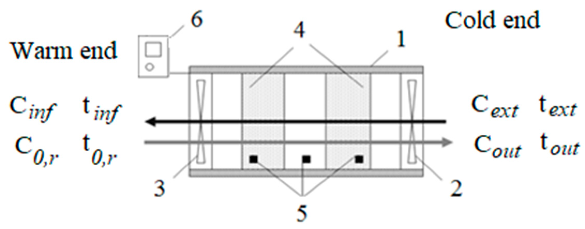
2.1. Adsorptive Regenerator

The design of the adsorptive heat-moisture regenerator is given in Figure 1, which is redrawn based on the heat regenerator scheme shown in [19]. The diameter of the laboratory prototype is 0.2 m, with a length of 0.6 m. As an adsorptive heat storage material, a silica gel–sodium sulphate composite synthesised by the sol–gel technique [33] was used. The device is operated in the two-phase mode, which involves alternating ‘inflow’ and ‘outflow’ stages [34]. The inner end of the investigated device is warm while the outer end is cold.

2.2. Adsorptive Regenerator Operation

The adsorptive regenerator is operated in the two-phase mode, which involves alternating ‘inflow’ and ‘outflow’ stages [34]. The inner end of the studied regenerator is warm while the outer end is cold. During the ‘outflow’ stage, air is drawn in by fan 3 from the interior and released into ambient medium, which results in increasing temperature of the adsorptive heat storage material (4) by ‘outflow’ air up to the necessary temperature of the interior. When the ‘inflow’ stage proceeds, fan 3 is switched off and fan 2 is switched on, and ambient air is drawn in and flows through the adsorbent into the interior heating air due to the adsorption of excess water. Thus, interior airing occurs at the constant temperature and humidity of internal air. The situation reverses during summer operation when the inner end can be termed as ‘cold’ and the outer end as ‘warm’. The operation principle of the adsorptive regenerator is, however, the same in both winter and summer.
The thickness of the adsorbent layer of the laboratory prototype is 0.6 m, i.e., 0.3 m per adsorbent holder. The laboratory prototype is filled with 3.5 kg of adsorbent. Air volumetric flow rates are up to 60 m3 per hour. Consumed fan power is 200 W for the laboratory setup. A silica gel–sodium sulphate composite obtained according to [33] is used as an adsorbent, with the size of its granules ranging from 2 to 3.5 mm.
The laboratory prototype was tested for air conditioning of a model interior of 1.5 to 10 m3 from December 2018 to February 2020 for 4 h per day; the outer air conditions corresponded with winter season conditions, i.e., very low temperatures and air close to saturation conditions. Temperature and relative humidity in the interior were kept within the intervals from 20 to 22 °C and 50% to 60%, respectively.

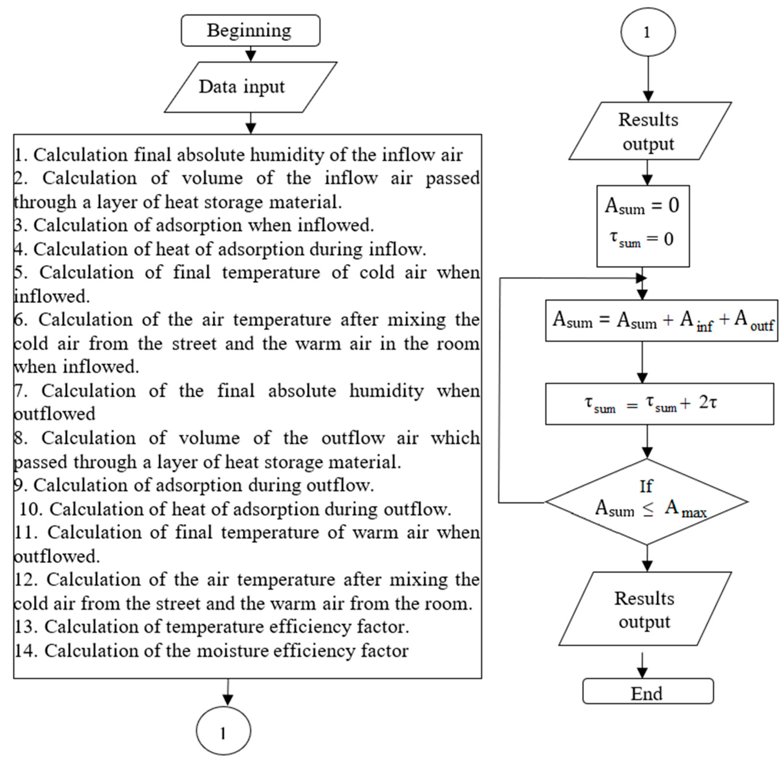
2.3. Data Processing

The algorithm proposed by Belyanovskaya et al. [19] for the calculation of the operating parameters of an adsorptive regenerator is further developed. As the efficiency criteria of the adsorptive heat-moisture regenerator, temperature efficiency factor, ηtem, and moisture efficiency factor, ηhum, were used, i.e., heat and moisture regeneration coefficients. A control-flow chart of the suggested algorithm is presented in Figure 2.
The algorithm includes the calculation of the temperature efficiency factor, Equation (1), according to [19,34]:
η t e m = t i n f t e x t t o u t t e x t ( - )
where ηtem is the temperature efficiency factor or heat regeneration coefficient; tinf is the temperature of inflowing air, °C; text is the temperature of external air; and tout is the temperature of outflowing air. The moisture efficiency factor or moisture regeneration coefficient is calculated using Equation (2) according to [19,25]:
η h u m = C e x t C i n f C e x t C o u t ( - )
where ηhum is the moisture efficiency factor or moisture regeneration coefficient; Cinf refers to the absolute humidity of the inflowing air, kg/m3; Cext is the absolute humidity of external air, kg/m3; and Cout is the absolute humidity of outflowing air, kg/m3. The absolute humidity of inflowing air is determined as the final absolute humidity of air when inflowed. The absolute humidity of outflowing air can be calculated as the absolute humidity after mixing the cold external air and warm exhaust air, according to Equation (3):
C f i n . s t r . a f t . m i x . = V s t r × C 0 , s t r + V o u t f × C f i n . s t r V s t r + V o u t f ( kg / m 3 )
where Vstr is the volume of air outflowing from the regenerator in the outflow operation stage, m3; C0.str is the initial absolute humidity of the outside air when leaving the interior, kg/m3; and Cfin.str is the final absolute humidity of warm air during outflow, kg/m3. The final absolute humidity of air near the outlet of the regenerator when inflowed or outflowed is calculated according to Equation (4) [19]:
C f i n = C 0 e [ β × ( τ × w . C 0 ) A m a x + H ] W + 1 ( kg / m 3 )
where Amax corresponds to the maximal adsorption, kg/kg; β refers to the mass transfer coefficient, s−1; w is the velocity of humid air, m/s; H is the thickness of the heat storage material layer, m; and τ is the time of inflow or outflow, s. The coefficient of mass transfer is calculated according to Equation (5) [19]:
β = ( 1 β y + 1 β l c + 1 β p ) 1 ( s 1 )
where 𝛽𝑦, 𝛽𝑙𝑐, 𝛽𝑝 are the coefficients of mass transfer in the gas phase in the longitudinal cross section and in pores, s−1. The temperature of the inflowing air is calculated as the temperature after the mixing of cold air from the exterior and warm air in the interior during inflow [19], according to Equation (6):
t f i n . r . a f t . m i x . = V r × t 0 r + V i n f × t f i n . r V r + V i n f ( ° C )
where Vr is the volume of the interior, m3; t0.r refers to the initial air temperature at the room outlet (warm end), °C; and tfin.r is the final temperature of the inflowing cold air, °C. The final temperature of cold air-in is calculated according to the equation of thermal balance, Equation (7):
t f i n . r = C × t 0 s t r × V i n f + 4.19 × t 0 s t r × V i n f × C 0 . s t r + Δ H a d s . i n f × M a d s ( C × V i n f + 4.19 × V i n f × C f i n . r ) ( ° C )
where C′ is the volumetric specific heat capacity of air, kJ/m3/°C; t0str is the temperature of external air (near the cold end of the regenerator), °C; Vinf is the volume of inflow air passed through a layer of heat storage material, m3; C0.str is the initial absolute humidity at the cold end of the regenerator, kg/m3; ΔHads.inf is the heat of adsorption during the inflow, kJ/kg; Mads is the mass of adsorbent, kg; and Cfin.r is the final absolute humidity of the inflow, kg/m3.
The volume of air passed through the layer of adsorbent during the inflow or outflow, Vinf or Voutf, m3, is determined by Equation (8):
V i n f / o u t f = F s × w × τ i n f / o u t f ( m 3 )
where w refers to the velocity of humid air, m/s; τ corresponds to the time of inflow or outflow, s; and Fs is the cross-sectional area of the regenerator, m2. The temperature of the outflowing air is calculated as the temperature after mixing cold air from the exterior and warm air from the interior during the outflow stage, according to Equation (9):
t f i n . s t r . a f t .   m i x .   = V s t r × t 0 . s t r + V o u t f × t f i n . s t r V s t r + V o u t f ( ° C )
where Vstr refers to the volume of air at the outside end of the regenerator, m3; t0.str is the initial temperature of the outside air leaving the room, °C; and tfin.str corresponds to the final temperature of warm air during outflow, °C. The final temperature of outflowing air is calculated by thermal balance, according to Equation (10):
t f i n . s t r .   = C × t 0 r × V o u t f + 4.19 × t 0 r × V o u t f × C 0 r + Δ H a d s . o u t f × M a d s C × V o u t f + 4.19 × V o u t f × C f i n . s t r ( ° C )
where C′ is the volumetric specific heat of air, kJ/m3 °C; t0r is the temperature of indoor air (near the warm end of the regenerator), °C; Voutf is the volume of air passed through the layer of heat-storage material during the outflow, m3; C0.r refers to the initial absolute humidity at the warm end of the regenerator, kg/m3; ΔHads.outf is the heat of adsorption at the outflow, kJ/kg; Mads is the adsorbent mass, kg; and Cfin.str is the final absolute humidity at the outflow, kg/m3.
Adsorption heat during the inflow or outflow is determined from Equation (11) [19]:
Δ H a d s = Δ h × A × 1000 μ H 2 O ( kJ )
where Δh is the adsorption heat, kJ/mole; A is adsorption during the inflow or outflow, kg/kg; and μH2O is the molar mass of water, g/mole. Adsorption during the inflow or outflow stage is determined using Equation (12):
A = C 0 C f i n M a d s × V ( kg / kg )
where V is the air volume passed through the adsorbent layer, m3; C0 is the initial absolute humidity at the inflow or outflow, kg/m3; Cfin. is the final absolute humidity at the inflow or outflow, kg/m3; and Mads is the adsorbent mass, kg.
Consumed fan power is determined as follows:
N = v × Δ p η vent ( W )
where N is the consumed fan power, W; v refers to the volumetric flow of air, m3/s; Δp refers to the pressure loss, Pa; and ηvent corresponds to the overall efficiency factor of the fan used.
Pressure loss is calculated from the Darcy–Weisbach equation in accordance with [35]:
Δ p = ξ × w 2 2 × ρ × H d e . ch ( Pa )
where Δp is the pressure loss, Pa; w corresponds to the humid air flow velocity, m/s; ξ corresponds to the hydrodynamic resistance of the adsorbent layer; ρ refers to the air density, kg/m3; H is the thickness of the adsorbent layer, m; and de.ch is the equivalent diameter of the channel, m.
The equivalent diameter of the channel is calculated according to [35]:
d e . ch = 2 3 × ε 1 ε × d ( m )
where ε corresponds to the fractional void volume; and d refers to the diameter of the adsorbent granule, m.
The value of the fractional void volume is assumed to be 0.259, which corresponds to the tightest alignment of spheres [35].
The hydrodynamic resistance of the adsorbent layer is calculated as [35]:
ξ = B R e l
where B is an empiric factor assumed to be 1900 [35] and Rel is the Reynolds criterion for air flow passed through the adsorbent layer. In accordance with the preliminary calculations, values of Rel are up to 30–40, which correspond to the laminar flow regime.
The design of the adsorptive regenerator is calculated according to the procedure given in Belyanovskaya et al. [34]. The structural characteristics of the adsorptive regenerator can be determined based on the load for inflow air heating per day, Qinf, by a normative procedure according to the Sanitary Regulations 2.04.05-91 [36], according to Equation (17):
  Q i n f = 0.28 × L i n f × ρ a i r × c × ( t i n t e x t ) × τ ( kJ )
where Linf corresponds to the inflowing air consumption, m3 per hour; ρair is the density of internal air, kg/m3; c refers to the specific heat capacity of air, kJ/(kg·°C); tin is the temperature of internal air, °C; text is the temperature of external air, °C; and τ is the operating period in hours per day. Then, the mass of adsorbent, Mads, in kg, is calculated as the ratio of load for inflow air heating per day and maximal heat of adsorption.
Maximal heat of adsorption is estimated by Equation (18):
Δ H a d s m a x = Δ h × A m a x × 1000 μ H 2 O ( kJ / kg )
where Δh ≈ 60 is the heat of water vapor adsorption, kJ/mole, adopted from Kim et al. (2016) [37]; Amax corresponds to the maximal adsorption, kg/kg; and μH2O refers to the molar mass of water, g/mole. Adsorbent volume is computed as the ratio of adsorbent mass and density. An adsorbent density of 720 kg/m3 was used in the above calculations.

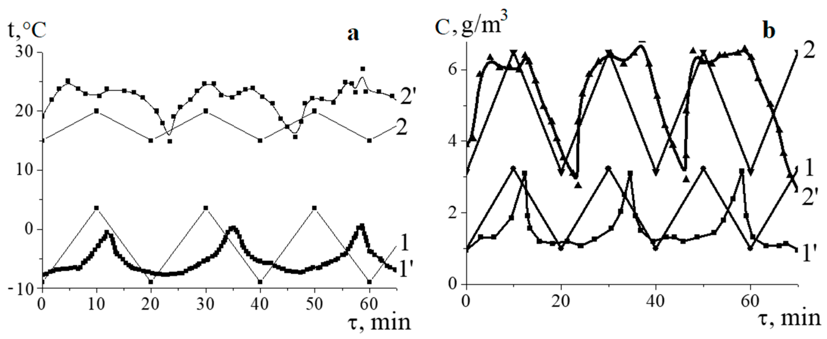
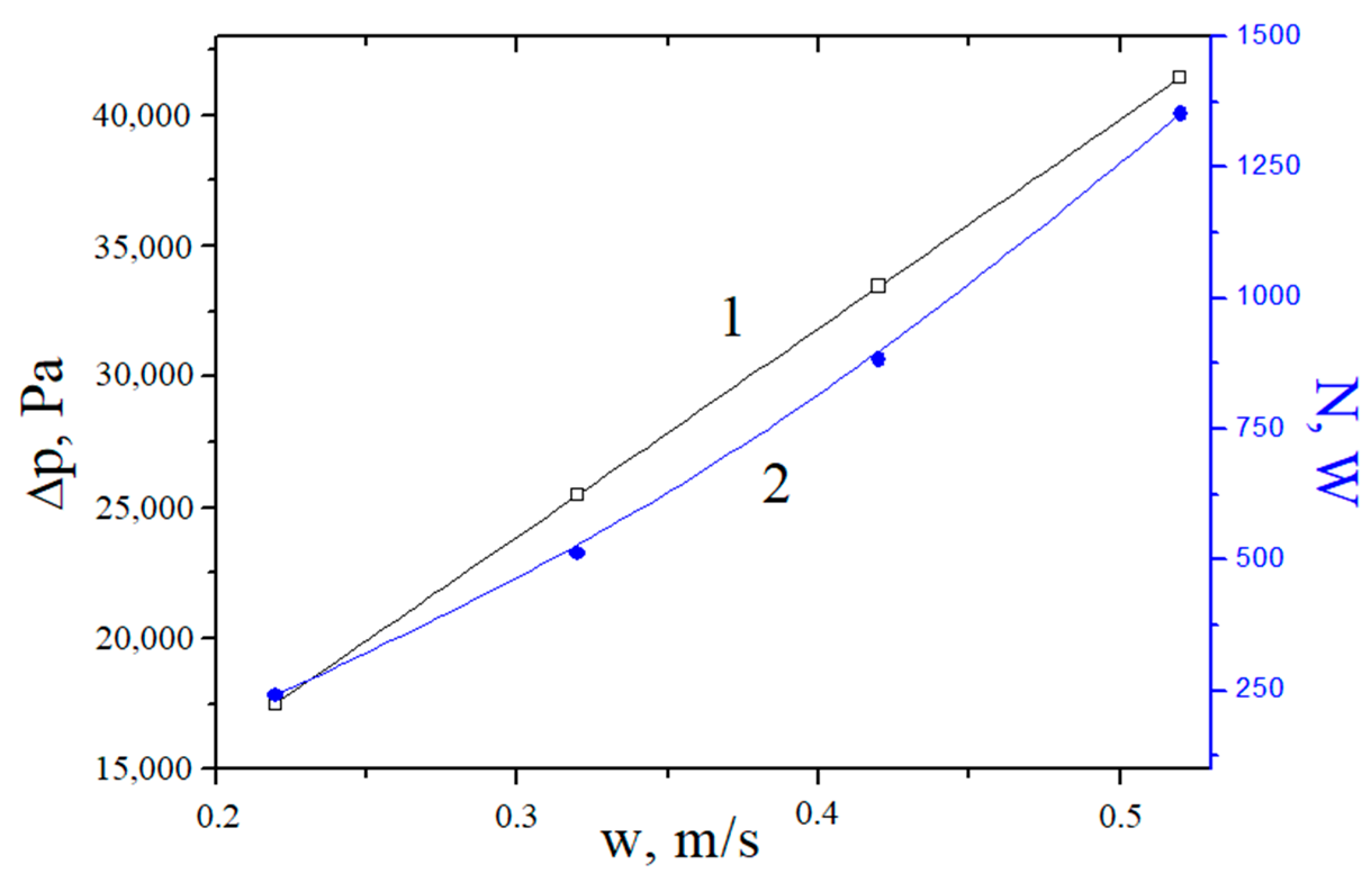
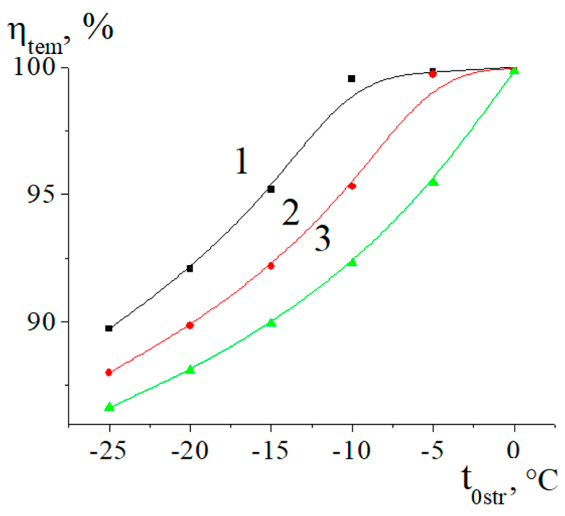
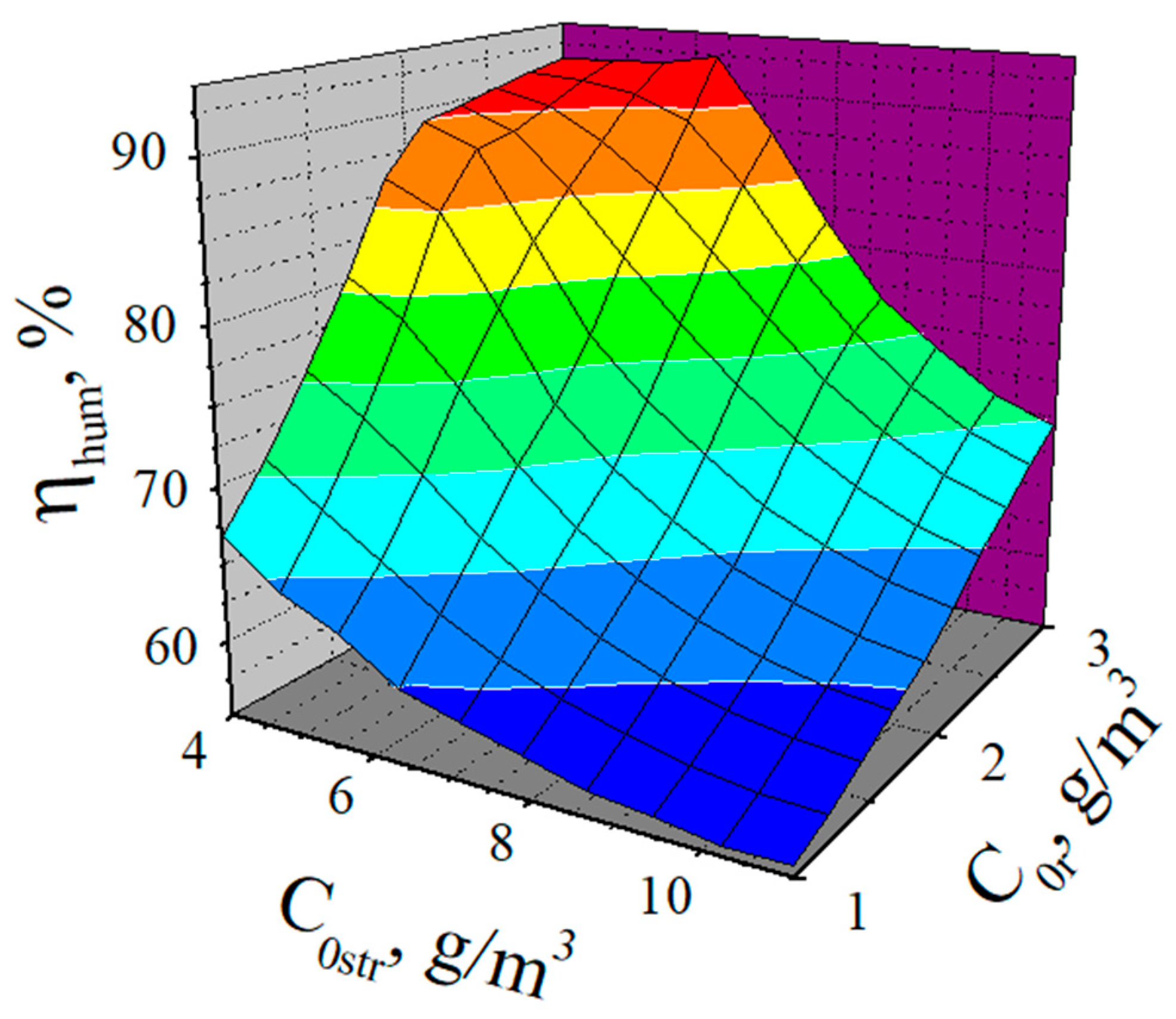
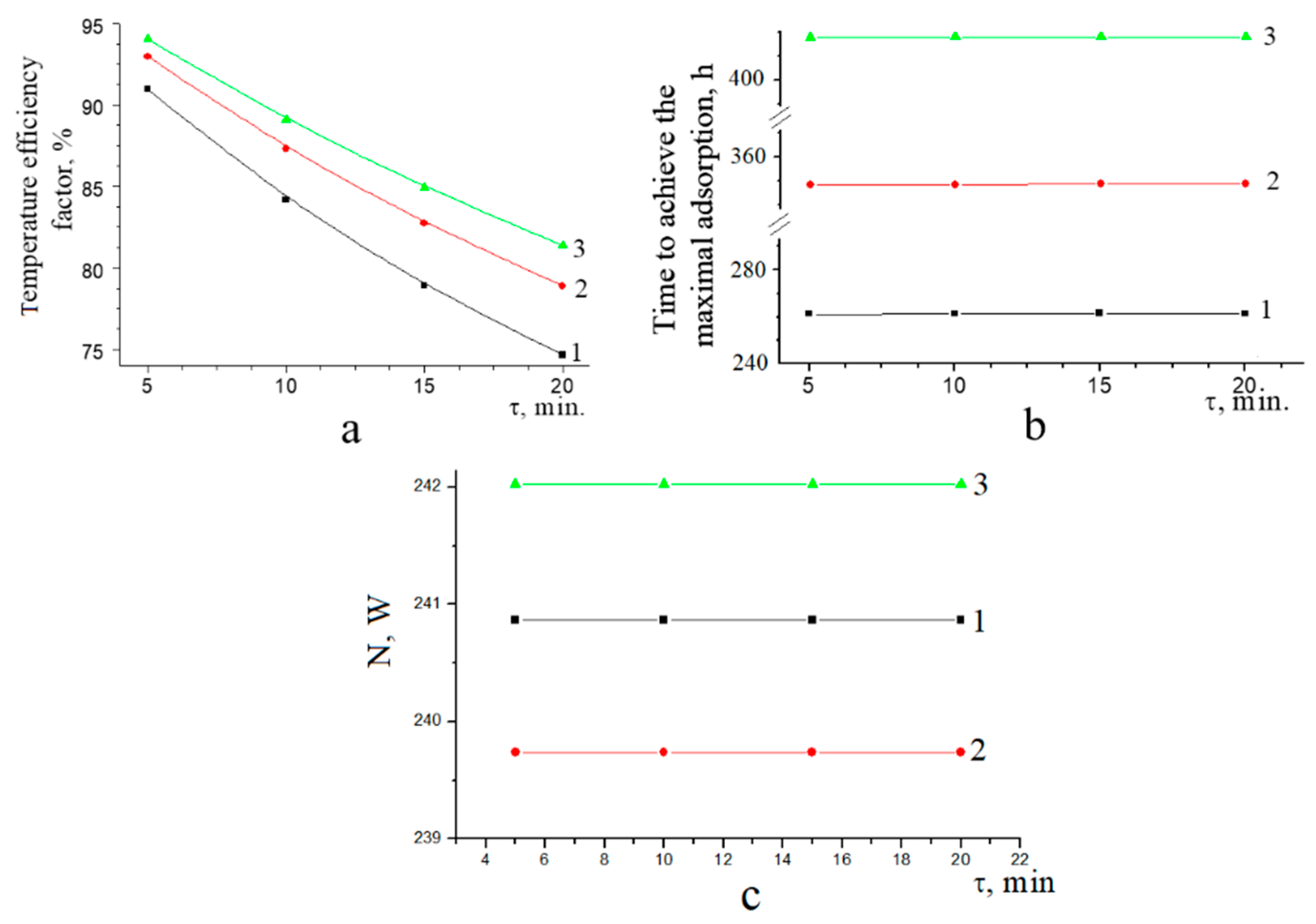
3. Results and Discussion

The results from the verification of the suggested algorithm are given in Figure 3. The calculation results show a periodical dependence of temperature and absolute humidity (Figure 3, curves 1 and 2), which qualitatively corresponds with the experimental data (Figure 3, curves 1′ and 2′). The difference between the experimental and calculated temperatures is below 2–3 °C and 1–5 °C at the cold and warm ends of the regenerator, respectively (Figure 3a). The difference between the experimental and computed values of absolute humidity does not exceed 1 g/m3 on either end of the regenerator (Figure 3b). The calculated values of the temperature and moisture efficiency factors are 91% and 59%, respectively, while their experimental values are 96% and 64%. It can be concluded that this mathematical model is suitable for qualitative evaluation of the performance characteristics of adsorptive heat-moisture regenerators in ventilation systems.
An adsorptive regenerator is a promising alternative for inflow air heating in the conditions of residential areas. The thermal load for heating the inflowing air in a three-room apartment with a total area of 77.5 m2 and ceiling height of 2.5 m is estimated to be 338.26 MJ per day according to the results of the calculation considering the Sanitary Regulations 2.04.05-91 [36], which corresponds to six working hours per day. Then, adsorbent mass and volume corresponding to the thermal load were determined by Equations (12)–(14).
The results of composite mass calculation are provided in Table 1. The most efficient adsorbent for inflow air heating is apparently the composite containing 80% sodium sulphate and 20% silica gel, providing appr. six times higher adsorption capacity than the low density polyethylene-silica gel composite adsorbent gel [20], four times higher than pulp coated with silica gel [22], twice that of the glass fibre-based composite adsorbent reported by Luo et al. [21] and 50% to 100% higher capacity than the sulphonic acid-modified silica investigated by Chen et al. [27]. The mass and volume of silica gel–sodium sulphate composite required to supply the calculated thermal load are estimated to be 96.5 kg and 0.134 m3, respectively. A thinner absorbent layer resulting from lower adsorbent mass reduces air pressure losses in the adsorbent layer, thus decreasing the fan power input and operational expenses. Due to the regenerator’s handling capability, it is advisable to install four smaller adsorptive regenerators instead of one large one, using 25 kg of the composite per regenerator of a volume of 0.035 m3.
The performance of the regenerator based on the selected composite was further assessed by a simulation in the conditions of a conventional ventilation system for residential areas. The switching-over periods, i.e., changing the direction of airflows and the amplitudes of time–temperature dependences, at both the cold and warm ends of the device follow the same trend. Absolute humidity near the cold end of the regenerator is changed similarly; however, it remains nearly constant near the warm end of the regenerator, which leads to an increase in temperature efficiency factor at a constant moisture efficiency factor of 59.1%. It should be noted that these values have been determined with vapour adsorption kinetics and absolute humidities of internal and external air only. Maximal values of the temperature efficiency factor can be achieved when the airflow velocity and switching-over period do not exceed 0.22 m/s and 5 min, respectively. The time to achieve maximal adsorption is strongly dependent on the airflow velocity. It monotonously decreases when airflow velocity increases because of simultaneous increases in the air volume and moisture quantity supplied to the adsorbent layer. The longest periods to achieve maximal adsorption were observed at the airflow velocity of 0.22 m/s.
Pressure loss and consumed fan power are strongly affected by the air flow velocity (Figure 4). Values of Δp and N increase proportionally, as do w and w2, according to Equations (13), (14) and (16). Obviously, the minimal value of consumed fan power of 250 W was at 0.22 m/s. The power input of standard air heating conditioners operating in an interior of 15–140 m2 ranges from 0.6 up to 2.9 kW [38]. Moreover, contrary to the adsorptive regenerator, which regulates both air temperature and humidity, commercial conditioners in the heating mode regulate only the relative humidity of internal air.
The efficiency of adsorptive heat-moisture regenerators is strongly affected by the meteorological conditions, i.e., temperature and absolute humidity of internal and external air (Figure 5). The temperature efficiency factor increases when the difference between the temperatures of internal and external air decreases. Maximal values of the temperature efficiency factor are observed in the internal and external temperature ranges of 15 to 20 °C and −5 to 0 °C, respectively.
From Figure 6, it follows that the moisture efficiency factor depends on the absolute humidity of external and internal air. Its values increase when the difference between the absolute humidities of external and internal air approaches the minimum, and it achieves maximal values at the absolute humidities of external and internal air of 4.0–5.0 g/m3 and 2.75–3.0 g/m3, respectively. Similarly, Kawamoto et al. [25] reported moisture efficiency factors of around 90% in an experimental air conditioning unit containing a desiccant (silica gel) wheel operated under spring ambient conditions (outer air temperature of 6 to 10 °C, outer air humidity of 1.8 to 5.9 g/kg, and supply air temperature of 20 °C and humidity of 6 g/kg).
The design parameters of the adsorptive regenerator strongly affect the temperature efficiency factor, time to achieve maximal adsorption and fan power consumption. Simultaneous increases in the cross-sectional area and volume of air passed through the adsorbent layer lead to a decrease in the temperature efficiency factor and time to achieve maximal adsorption (see Figure 7). Maximal values of temperature efficiency factor correspond to a cross-sectional area of the adsorbent layer of 0.03925 m2. Moisture efficiency factor remains almost constant, reaching a value of 59.1%. Regenerator fan power input is neither a function of the regenerator operation time nor of the adsorbent layer thickness and cross section.

4. Conclusions

The operation of an adsorptive heat-moisture regenerator based on silica gel–sodium sulphate composite adsorbent has been studied, determining the main performance parameters that affect the efficiency of the device.
An algorithm for the calculation of temperature and moisture efficiency factors, allowing the estimation of the key operating characteristics of the device, has been suggested. A satisfactory correlation between the calculation results obtained using the proposed algorithm and experimental data was achieved. The power input of the regenerator fan has been evaluated as a part of the mathematical model.
A correlation between the composition of the adsorbent and the regenerator design has been found and further investigated. An increase in the temperature efficiency factor occurs with a decrease in the airflow velocity and prolongation of switching-over time. Temperature efficiency factor, time to achieve maximal adsorption and consumed fan power can be used as optimisation criteria for adsorptive heat-moisture regenerator operation. Moreover, the temperature efficiency factor can be optimised without negatively affecting the humidity factor. This is an important finding, which means that an increase in regenerator operation efficiency can be achieved by adjusting the operation parameters.
The efficiency of the adsorptive regenerator is also affected by its design parameters. Maximal values of temperature efficiency factor and time to achieve maximal adsorption were determined at a cross-sectional area of the adsorbent layer of 0.03925 m2.
The results and their analysis confirm the correlation between the meteorological conditions and the efficiency factors. Maximal values of temperature efficiency factors were reached when the temperatures of internal and external air change within the range of 15 to 20 °C and −5 to 0 °C, respectively. Maximal efficiency factors were achieved at the absolute humidities of external and internal air of 4.0 to 5.0 g/m3 and 2.75 to 3.0 g/m3, respectively. A regenerator power consumption of 0.25 to 1.3 kW was found, which is comparable to or lower than that of commercial air handling units in the heating mode (0.6 to 2.9 kW) for interiors with comparable heated volume, depending on the adsorbent layer thickness and air flow velocities.

Author Contributions

Conceptualisation, E.B. and K.M.S.; methodology, M.P.S. and O.O.Y.; software, R.D.L.; validation, R.D.L., E.M.P. and J.K.; investigation, E.M.P. and J.K.; resources, M.P.S. and I.V.S.; data curation, E.B. and K.M.S.; writing—original draft preparation, I.V.S. and M.V.G.; writing—review and editing, E.B., M.V. and M.R.; visualisation, J.K. and M.V.; project administration, O.O.Y. and M.V.G.; funding acquisition, M.R. All authors have read and agreed to the published version of the manuscript.

Funding

This work was financially supported within the framework of the budget project of the Ministry of Education and Science of Ukraine (grant number 0119U002243), as well as by the Slovak Research and Development Agency under contract no.s APVV-16-0192 and APVV-15-0148.

Conflicts of Interest

The authors declare no conflict of interest.

Nomenclature

Symbols and abbreviations
Aadsorption(kg/kg)
Bempiric factor (Equation (16))
cspecific heat capacity of air(kJ/(kg·°C))
Cvolumetric heat capacity of air(kJ/(m3·°C))
Cabsolute humidity(kg/m3)
ddiameter(m)
Hthickness(m)
ΔHspecific heat of water vapour adsorption(kJ/kg)
Δhmolar heat of water vapour adsorption(kJ/mole)
Farea(m2)
Lair consumption(m3 per hour)
Mmass(kg)
Nfan power input(W)
Qheat load(kJ)
Δppressure difference(Pa)
RelReynolds criterion for flow through adsorbent layer
ttemperature(°C)
Vvolume(m3)
vvolumetric flowm3/s)
wvelocity(m/s)
Subscripts
adsadsorbent
ads.infadsorption inflow
aft.mix.after mixing
airair
e.chrelated to channel (in adsorbent layer)
extexternal
fin.final
H2Owater
hummoisture
infinflow
ininternal
lclongitudinal cross section
maxmaximal
outoutgoing
outfoutflow
ppores
rregenerator
0rwarm end of regenerator
temtemperature
scross section
stroutside
ventrelated to fan (fan efficiency)
ygas phase
Greek symbols
βmass transfer coefficient(s−1)
ηefficiency(-)
εfractional void volume
ξhydrodynamic resistance of adsorbent layer
μmolar mass(g/mole)
ρdensity(kg/m3)
τtime(s)

References

  1. Sarbu, I.; Serbachievici, C. A Comprehensive Review of Thermal Energy Storage. Sustainability 2018, 10, 191. [Google Scholar] [CrossRef] [Green Version]
  2. European Commission. European Commission. European Union Energy in Figures. In Statistical Pocketbook; Publications Office of the EU: Luxembourg, 2016. [Google Scholar]
  3. Kim, B.-J.; Park, J.; Jeong, J.-W. Indoor Air Quality Enhancement Performance of Liquid Desiccant and Evaporative Cooling-Assisted Air Conditioning Systems. Sustainability 2019, 11, 1036. [Google Scholar] [CrossRef] [Green Version]
  4. Ligade, J.; Razban, A. Investigation of Energy Efficient Retrofit HVAC Systems for a University: Case Study. Sustainability 2019, 11, 5593. [Google Scholar] [CrossRef] [Green Version]
  5. Chiang, C.-Y.; Yang, R.; Yang, K.-H.; Lee, S.-K. Performance Analysis of an Integrated Heat Pump with Air-Conditioning System for the Existing Hospital Building Application. Sustainability 2017, 9, 530. [Google Scholar] [CrossRef] [Green Version]
  6. Elhelw, M. Performance Evaluation for Solar Liquid Desiccant Air Dehumidification System. Alex. Eng. J. 2016, 55, 933–940. [Google Scholar] [CrossRef] [Green Version]
  7. Qin, M.; Hou, P.; Wu, Z.; Wang, J. Precise Humidity Control Materials for Autonomous Regulation of Indoor Moisture. Build. Environ. 2020, 169, 106581. [Google Scholar] [CrossRef]
  8. Yuan, J.; Emura, K.; Farnham, C. Effects of Recent Climate Change on Hourly Weather Data for HVAC Design: A Case Study of Osaka. Sustainability 2018, 10, 861. [Google Scholar] [CrossRef] [Green Version]
  9. Corsini, A.; Delibra, G.; Di Meo, G.; Martini, M.; Rispoli, F.; Santoriello, A. A CFD-based Virtual Test-rig for Rotating Heat Exchangers. Energy Procedia 2015, 82, 245–251. [Google Scholar] [CrossRef] [Green Version]
  10. Tyfour, W.R.; Tashtoush, G.; Al-Khayyat, A. Design and Testing of a Ready-to-use Standalone Hot Air Space Heating System. Energy Procedia 2015, 74, 1228–1238. [Google Scholar] [CrossRef] [Green Version]
  11. Aristov, Y.I. Current Progress in Adsorption Technologies for Low-Energy Buildings. Future Cities Environ. 2015, 1. [Google Scholar] [CrossRef]
  12. Aristov, Y.I. VENTIREG—A New Approach to Regenerating Heat and Moisture in Dwellings in Cold Countries. In Desiccant Heating, Ventilating, and Air-Conditioning Systems; Enteria, N., Awbi, H., Yoshino, H., Eds.; Springer: Singapore, 2018; pp. 87–107. [Google Scholar]
  13. Bareschino, P.; Pepe, F.; Roselli, C.; Sasso, M.; Tariello, F. Desiccant-Based Air Handling Unit Alternatively Equipped with Three Hygroscopic Materials and Driven by Solar Energy. Energies 2019, 12, 1543. [Google Scholar] [CrossRef] [Green Version]
  14. Rogala, Z.; Kolasiński, P. Exergy Analysis of Fluidized Desiccant Cooling System. Entropy 2019, 21, 757. [Google Scholar] [CrossRef] [Green Version]
  15. Yang, K.-S.; Wang, J.-S.; Wu, S.-K.; Tseng, C.-Y.; Shyu, J.-C. Performance Evaluation of a Desiccant Dehumidifier with a Heat Recovery Unit. Energies 2017, 10, 2006. [Google Scholar] [CrossRef] [Green Version]
  16. Ge, T.S.; Qi, D.; Dai, Y.J.; Wang, R.Z. Experimental Testing on Contaminant and Moisture Removal Performance of Silica Gel Desiccant Wheel. Energy Build. 2018, 176, 71–77. [Google Scholar] [CrossRef]
  17. Aristov, Y.I. New Family of Solid Sorbents for Adsorptive Cooling: Material Scientist Approach. J. Eng. Thermophys. 2007, 16, 63–72. [Google Scholar] [CrossRef]
  18. Belyanovskaya, E.A.; Pustovoy, G.N.; Sukhyy, K.M.; Sergiyenko, Y.O.; Yeromin, O.O.; Prokopenko, E.M.; Gubinskyi, M.V.; Kizek, J.; Lukáč, L. Adsorptive Solar Refrigerators Based on Composite Adsorbents ‘Silica Gel—Sodium Sulphate’. Civ. Environ. Eng. Rep. 2019, 29, 200–208. [Google Scholar] [CrossRef] [Green Version]
  19. Belyanovskaya, E.; Lytovchenko, R.; Sukhyyy, K.; Yeremin, O.; Sukha, I.; Prokopenko, E. Operating Regime of Adsorptive Heat-Moisture Regenerators Based on Composites «Silica Gel—Sodium Sulphate» and «Silica Gel—Sodium Acetate». J. Chem. Technol. 2019, 27, 158–168. [Google Scholar] [CrossRef] [Green Version]
  20. Sangerlaub, S.; Kucukpinar, E.; Muller, K. Desiccant Films Made of Low-Density Polyethylene with Dispersed Silica Gel-Water Vapor Absorption, Permeability (H2O, N2, O2, CO2), and Mechanical Properties. Materials (Basel) 2019, 12, 2304. [Google Scholar] [CrossRef] [Green Version]
  21. Luo, Y.; Tan, B.; Liang, X.; Wang, S.; Gao, X.; Zhang, Z.; Fang, Y. Dry Gel Conversion Synthesis and Performance of Glass-Fiber MIL-100(Fe) Composite Desiccant Material for Dehumidification. Microporous Mesoporous Mater. 2020, 297, 110034. [Google Scholar] [CrossRef]
  22. Wu, X.N.; Ge, T.S.; Dai, Y.J.; Wang, R.Z. Investigation on Novel Desiccant Wheel Using Wood Pulp Fiber Paper with High Coating Ratio as Matrix. Energy 2019, 176, 493–504. [Google Scholar] [CrossRef]
  23. Chua, K.J.; Chou, S.K.; Islam, M.R. Integrating Composite Desiccant and Membrane Dehumidifier to Enhance Building Energy Efficiency. Energy Procedia 2017, 143, 186–191. [Google Scholar] [CrossRef]
  24. Kumar, A.; Yadav, A. Experimental Investigation of Solar Driven Desiccant Air Conditioning System Based on Silica Gel Coated Heat Exchanger. Int. J. Refrig. 2016, 69, 51–63. [Google Scholar] [CrossRef]
  25. Kawamoto, K.; Cho, W.; Kohno, H.; Koganei, M.; Ooka, R.; Kato, S. Field Study on Humidification Performance of a Desiccant Air-Conditioning System Combined with a Heat Pump. Energies 2016, 9, 89. [Google Scholar] [CrossRef] [Green Version]
  26. Gaeini, M.; Zondag, H.A.; Rindt, C.C.M. Effect of Kinetics on the Thermal Performance of a Sorption Heat Storage Reactor. Appl. Therm. Eng. 2016, 102, 520–531. [Google Scholar] [CrossRef]
  27. Chen, H.; Wang, W.; Wei, X.; Ding, J.; Yang, J. Experimental and Numerical Study on Water Sorption over Modified Mesoporous Silica. Adsorption 2015, 21, 67–75. [Google Scholar] [CrossRef]
  28. Intini, M.; De Antonellis, S.; Joppolo, C.M. The Effect of Inlet Velocity and Unbalanced Flows on Optimal Working Conditions of Silica Gel Desiccant Wheels. Energy Procedia 2014, 48, 858–864. [Google Scholar] [CrossRef] [Green Version]
  29. Rafique, M.; Rehman, S.; Alhems, L.; Lashin, A. Parametric Analysis of a Rotary Type Liquid Desiccant Air Conditioning System. Energies 2016, 9, 305. [Google Scholar] [CrossRef] [Green Version]
  30. Narayanan, R.; Halawa, E.; Jain, S. Dehumidification Potential of a Solid Desiccant Based Evaporative Cooling System with an Enthalpy Exchanger Operating in Subtropical and Tropical Climates. Energies 2019, 12, 2704. [Google Scholar] [CrossRef] [Green Version]
  31. Luo, W.-J.; Faridah, D.; Fasya, F.R.; Chen, Y.-S.; Mulki, F.H.; Adilah, U.N. Performance Enhancement of Hybrid Solid Desiccant Cooling Systems by Integrating Solar Water Collectors in Taiwan. Energies 2019, 12, 3470. [Google Scholar] [CrossRef] [Green Version]
  32. Ukai, M.; Okumiya, M.; Tanaka, H. Energy Performance Evaluation of a Desiccant Air Handling System to Maximize Solar Thermal Energy Use in a Hot and Humid Climate. Sustainability 2020, 12, 1921. [Google Scholar] [CrossRef] [Green Version]
  33. Serhiienko, Y.; Sukhyy, K.; Belyanovskaya, E.; Kolomiyets, E.; Gubynskyi, M.; Tkalya, O.; Sukha, I.; Zaichuk, O. Technology of Obtaining New Materials for Adsorptive Heat Energy Transformation Type of «Silica Gel—Crystalline Hydrate». J. Chem. Technol. 2020, 27, 239–246. [Google Scholar] [CrossRef]
  34. Belyanovskaya, E.A.; Lytovchenko, R.D.; Sukhyy, K.M.; Prokopenko, O.M.; Yeromin, O.O.; Sukha, I.V. Choice Criteria of Adsorbents for Heat Energy Converters in Ventilation Systems. Sci. Work. 2019, 83, 3–9. [Google Scholar] [CrossRef] [Green Version]
  35. Bratchikov, S.G.M. (Ed.) Heat Engineering of Lumping of Iron Ore Raw Materials; Metallurgia: Moskaw, Soviet Union, 1970; 344p. [Google Scholar]
  36. Sanitary Regulations 2.04.05-91. Heat Supply, Ventilation and Conditioning. Moscow. 1997, p. 74. (In Russian). Available online: https://files.stroyinf.ru/Data2/1/4294854/4294854695.pdf (accessed on 13 January 2020).
  37. Kim, H.; Cho, H.J.; Narayanan, S.; Yang, S.; Furukawa, H.; Schiffres, S.; Li, X.; Zhang, Y.B.; Jiang, J.; Yaghi, O.M.; et al. Characterization of Adsorption Enthalpy of Novel Water-Stable Zeolites and Metal-Organic Frameworks. Sci. Rep. 2016, 6, 19097. [Google Scholar] [CrossRef] [PubMed] [Green Version]
  38. Ananyev, V.A.; Baluyeva, L.N.; Galperin, A.D.; Gorodov, A.K.; Yereomin, M.Y.; Zvyagintseva, S.M.; Murashko, V.P.; Sedykh, I.V. Systems of Ventilation and Conditioning. Theory and Practice (in Russian); Yevroklimat: Moskaw, Russia, 2001; 416p. [Google Scholar]
Figure 1. Heat regenerator construction. Legend: 1—pipe (case); 2— external fan; 3—inner fan; 4—adsorptive heat storage material; 5—temperature detector; 6—operating console. Source: [19].
Sustainability 12 05611 g001
Figure 2. Control-flow chart for the calculation of an adsorptive regenerator’s efficiency factors.
Sustainability 12 05611 g002
Figure 3. (a,b) Periodic dependence of temperature (a) and absolute humidity (b) for adsorptive heat regenerator based on silica gel–sodium sulphate composite. Legend (a): 1, 2—calculation results; 1′, 2′—experimental data. 1, 1′—air temperatures at the cold end of the regenerator; 2, 2′—air temperatures at the warm end of the regenerator. Legend (b): 1, 2—calculation results; 1′, 2′—experimental data. 1, 1′—air humidities at the cold end of the regenerator; 2, 2′—air humidities at the warm end of the regenerator.
Sustainability 12 05611 g003
Figure 4. Pressure loss (1) and consumed power (2) of adsorptive heat-moisture regenerator vs. air flow velocity.
Sustainability 12 05611 g004
Figure 5. Temperature efficiency factor vs. external temperature. Legend: internal temperature, °C: 1–15; 2–20; 3–25.
Sustainability 12 05611 g005
Figure 6. Moisture efficiency factor vs. absolute humidity of internal and external air. Parameters used in the calculation: airflow velocity of 0.22 m/s, temperature of external air of −23 °C, temperature of internal air of 25 °C, thickness of the adsorbent layer of 1.1 m, cross-sectional area of the regenerator of 0.0314 m2.
Sustainability 12 05611 g006
Figure 7. (ac) Temperature efficiency factor (a), time to achieve maximal adsorption (b) and consumed fan power (c) vs. switching-over time of adsorptive heat-moisture regenerator based on silica gel–sodium sulphate composite. Absolute humidity of external air is 6.5 g/m3, absolute humidity of internal air is 1.0 g/m3. Legend: cross-sectional area of the adsorbent layer, m2, and thickness of the adsorbent layer, m: 1: 0.0628 and 0.53; 2: 0.0471 and 0.70; 3: 0.03925 and 0.848.
Sustainability 12 05611 g007
Table 1. Results of the heat of adsorption and adsorbent mass calculation for inflow air heating (thermal load of 338.26 MJ per day).
Silica Gel, %Na2SO4, %Maximal Adsorption, Amax, kg/kgMaximal Heat of AdsorptionMadsVads
Δ H a d s m a x Δ ,   kJ / kg kgm3
20801.055350696.50.134
40600.8422807120.50.167
60400.6282093161.60.22
80200.4141380245.10.34

