Article

Modeling In-Vehicle VOCs Distribution from Cabin Interior Surfaces under Solar Radiation

1
State Key Laboratory of Fluid Power and Mechatronic Systems, Zhejiang University, Hangzhou 310027, China
2
School of Mechanical Engineering, Zhejiang University, Hangzhou 310027, China
*
Author to whom correspondence should be addressed.
Sustainability 2020, 12(14), 5526; https://doi.org/10.3390/su12145526
Submission received: 7 June 2020 / Revised: 3 July 2020 / Accepted: 5 July 2020 / Published: 8 July 2020
(This article belongs to the Special Issue Sustainable Building and Indoor Air Quality)

Abstract

:
In-vehicle air pollution has become a public health priority worldwide, especially for volatile organic compounds (VOCs) emitted from the vehicle interiors. Although existing literature shows VOCs emission is temperature-dependent, the impact of solar radiation on VOCs distribution in enclosed cabin space is not well understood. Here we made an early effort to investigate the VOCs levels in vehicle microenvironments using numerical modeling. We evaluated the model performance using a number of turbulence and radiation model combinations to predict heat transfer coupled with natural convection, heat conduction and radiation with a laboratory airship. The Shear–Stress Transport (SST) k-ω model, Surface-to-surface (S2S) model and solar load model were employed to investigate the thermal environment of a closed automobile cabin under solar radiation in the summer. A VOCs emission model was employed to simulate the spatial distribution of VOCs. Our finding shows that solar radiation plays a critical role in determining the temperature distribution in the cabin, which can increase by 30 °C for directly exposed cabin surfaces and 10 °C for shaded ones, respectively. Ignoring the thermal radiation reduced the accuracy of temperature and airflow prediction. Due to the strong temperature dependence, the hotter interiors such as the dashboard and rear board released more VOCs per unit time and area. A VOC plume rose from the interior sources as a result of the thermal buoyancy flow. A total of 19 mg of VOCs was released from the interiors within two simulated hours from 10:00 am to noon. The findings, such as modeled spatial distributions of VOCs, provide a key reference to automakers, who are paying increasing attention to cabin environment and the health of drivers and passengers.

1. Introduction

Over the past decades, China has been experiencing the world’s fastest growth in vehicle population. As a result, commuters inevitably spend a substantial amount of time in vehicle cabins due to increased traffic congestions and vehicle population especially in major cities [1]. Epidemiological studies show that long-time exposure to air pollutants is associated with increased risks of morbidity and mortality [2,3,4], especially high volatile organic compounds (VOCs) concentrations emitted from cabin interiors [5,6,7] that could lead to respiratory irritation and cancer [8]. Developing advanced methods to identify in-cabin emission sources [9] has become a public health priority for consumers, car producers and government. Some attempts have been made to provide indoor air quality (IAQ) guidelines for passenger cars. For example, the Ministry of Environmental Protection of the People’s Republic of China has promulgated national standard the HJ/T 400 “Determination of Volatile Organic Compounds and Carbonyl Compounds in Cabin of Vehicles” and GB/T 27,630 “Guideline for air quality assessment of passenger car”. The Japan Automobile Manufacturers Association (JAMA) has introduced a voluntary approach for reducing the concentration levels of VOCs in the vehicle cabins. The World Health Organization (WHO) provides a guideline of 0.1 mg/m3 for the protection of public health from risks due to a number of chemicals commonly found in indoor air [10,11].
The factors controlling in-vehicle VOCs levels have been identified as a combined impact of interior materials, vehicle age [12,13], microenvironment in the cabin such as temperature, relative humidity and ventilation mode [14,15], and pollutants outside the vehicle like exhaust gases [16] and fuel leakage [9]. However, for a certain parked vehicle with the engine and ventilation off, the cabin becomes a completely closed space ignoring the air leakage, and it can be reasonably inferred that temperature becomes the main factor. Some researchers have addressed that VOCs diffusing from building materials are strongly associated with temperature [17,18,19]. Similar studies also were carried out in vehicle with an increased focus on cabin air quality. Many evidences have proved that the VOCs concentrations significantly increased with the increase in surface and ambient temperature. Yoshida et al. [20] indicated that the total volatile organic compounds (TVOC) concentrations in summer exceeded the indoor guideline value of 300 μg/m3; the interior temperature was the main factor affecting the interior concentrations of most compounds. Geiss et al. [21] found the VOC concentrations in the hot cabin with 70 °C were 40% higher through measuring in 23 old private cars in both summer and winter. Faber et al. [22] presented that chemical composition in vehicle air strongly depends on temperature. Chen et al. [23] investigated the VOCs in taxi cabins and found vehicle age is the most important factor, followed by interior temperature. Xiong et al. [24] derived a theoretical correlation between the steady state concentration and temperature for VOC emission from materials performing on three cars at different temperatures. Xu et al. [13] found toluene, styrene, ethylbenzene, and xylene were the most sensitive VOCs to temperature, which increased by 513.6%, 544.8%, 767.0%, and 597.7%, respectively, as the temperature increased from 11 °C to 25 °C. Huang et al. [25] found that the TVOC emission rate exponentially increased with the increase in in-cabin temperature.
As mentioned above, the VOCs emission is significantly associated with the in-cabin thermal environment, which is currently a hot topic. To evaluate the thermal comfort in cabin and further optimize the heating, ventilation, and air conditioning (HVAC) system [26,27,28], both experimental and numerical simulation studies have investigated the unsteady temperature and airflow profiles in buildings and passenger compartments [29,30,31,32,33,34,35,36]. Some studies have documented the dangerously high temperature in passenger compartments during exposure to the sun when parked outdoors [37]. Solar radiation is identified as the main heat source for a static vehicle in summer. More than 40% of solar heat flux enters the vehicle via the windshield. The vehicle exposed to direct solar radiation performs comparably to a greenhouse with severe thermal accumulation [38]. The cabin tends to be overheated quickly during the thermal soak period, the terminal temperature of the air and interior can reach about 60 °C and 80 °C, respectively [39,40].
This brief review shows that VOCs released from cabin interiors are proven to be temperature-dependent, and thermal simulation of the cabin environment has been conducted before. However, they were not linked together to discuss the in-cabin air quality. How VOC concentrations in the cabin vary with temperature under parked conditions is still a problem that has not been investigated quantitatively before. Gas sensing in real conditions with the use of cost-acceptable sensors is not trivial task [41], therefore, the numerical approximation of VOC distribution modeling in the car will be better justified. This research was aimed at bridging this knowledge gap and providing an effort to quantify the impact of the solar radiation on the cabin temperature and VOCs emission. This paper is organized as follows. We first evaluate the model performance by comparing it to the experiment in Section 2. Then, in-vehicle VOCs distribution from interior surfaces under solar radiation is modelled in Section 3. Section 4 presents the results and discussions. Concluding remarks are provided in Section 5.

2. Numerical Development and Verification

Computational fluid dynamics (CFD) has proved itself to be a powerful numerical tool in modeling the in-cabin environment. Figure 1 describes our analytical procedure based on the CFD approach. The solar calculator was imposed to compute the solar irradiation. The solar load model was used to calculate radiation effects from the sun’s rays that enter the cabin domain. Turbulence and radiation models were applied to capture the airflow and temperature. The pollutant emission model linked the temperature and emission rate (ER) of the cabin interiors. Then, the data of hot-soak temperature, airflow distribution and pollutant concentration were obtained.

2.1. The Turbulence Models

Turbulence modeling is a critical process for the numerical investigation of thermal environments. There have been some available studies to evaluate the performance of various turbulence models. Zhai et al. [42] compared eight turbulence models for predicting airflow and turbulence in enclosed environments and found that the Re-Normalization Group (RNG) k-ε model performed best among the Reynolds-averaged Navier–Stokes (RANS) models. Hussain et al. [43] used six RANS turbulence models to simulate the thermal environment in an atrium, and found the Shear–Stress Transport (SST) k-ω model provided comparatively better results. Li et al. [44] presented a numerical evaluation of the eddy viscosity turbulence models in terms of CFD modeling of convection-radiation coupled heat transfer in the indoor environment, and demonstrated a great performance of k-ω group models. In this study, five RANS turbulence models (including the standard k-ε model, the RNG k-ε model, the realizable k-ε model, the standard k-ω model, the SST k-ω model) and the Large Eddy Simulation (LES) model were selected to evaluate the prediction of the airflow and temperature distributions in the vehicle cabin.

2.2. The Radiation Models

Thermal radiation makes the temperature distribution more uniform in an enclosed space by transferring thermal energy from a hot surface to a cold one. Generally, thermal radiation accounts for 30–70% of the total heat transfer rate [45]. In this study, radiation heat transfer was taken into consideration for modeling the cabin thermal environment.
The P-1 radiation model is the simplest case of the P-N model, which is based on the expansion of the radiation intensity into an orthogonal series of spherical harmonics functions. The directional dependence in radiative transfer equation (RTE) is integrated out, resulting in a diffusion equation for incident radiation. Equation (1) is obtained for the radiation flux q r , only considering scattering and absorption when modeling gray radiation.
q r = 1 3 ( a + σ s ) C σ s G
An advection-diffusion equation is solved to determine the local radiation intensity G in the P-1 model.
· q r = a G 4 σ T 4
where q r is the radiation heat flux, a is the absorption coefficient, σ s is the scattering coefficient, G is the incident radiation, C is the linear-anisotropic phase function coefficient, σ is the Stefan-Boltzmann constant.
The Surface to Surface (S2S) radiation model is applicable for modeling radiation in situations where there are no participating media. All surfaces involved in radiation are assumed to be gray and diffuse, ignoring absorption, emission and scattering and preserving only “surface-to-surface” radiation. The energy flux leaving a given surface is composed of directly emitted and reflected energy. The reflected energy flux is dependent on the incident energy flux from the surroundings, which then can be expressed in terms of the energy flux leaving all other surfaces. The energy leaving from the kth adiabatic surface can be expressed as Equation (3).
q o u t , k = ε k σ T k 4 + ρ k q i n , k
where q o u t , k is the energy flux leaving the surface, ε k is the emissivity, ρ k is the reflectivity of surface k, q i n , k is the energy flux incident on the surface from the surroundings.
The Discrete Ordinates (DO) radiation model is regarded as the most comprehensive radiation model, which solves the RTE for a discrete number of finite solid angles, as shown in Equation (4). Each associated with a vector direction s is fixed in the global Cartesian system (x, y, z). Accuracy can be increased by using a better discretization, while it may be CPU-intensive with many ordinates.
· ( I ( r , s ) s ) + ( a + σ s ) I ( r , s ) = a n 2 σ T 4 4 π + σ s 4 π 0 4 π I ( r , s ) Φ ( s · s ) d Ω
where r is the position vector, s is the direction vector, s is the scattering direction vector, α is the absorption coefficient, n is the refractive index, I is the radiation intensity, which depends on the position ( r ) and direction ( s ) , T is the local temperature, Φ is the phase function, Ω is the solid angle.
For the Discrete Transfer Radiation Model (DTRM), the main assumption is that radiation leaving a surface element within a specified range of solid angles can be approximated by a single ray. The energy source in the fluid due to radiation is computed by summing the change in intensity d I along the path of each ray d s that is traced through the fluid control volume.
d I d s + a I = a σ T 4 π

2.3. The Solar Load Model (SLM)

Thermal energy due to incident solar rays is a very common but important phenomenon. In the SLM, the solar beam direction and irradiation were calculated according to the provided geographical place and the given time based on the solar load model’s ray tracing algorithm. A two-band spectral model was used for direct solar illumination and accounted for separate material properties in the visible and infrared bands. A single-band hemispherical-averaged spectral model was used for diffuse radiation. The ground was considered to be dry bare land with a reflectivity of 0.2 [40]. Solar scattering was set to the default value of 1.

2.4. Contaminants Emission Model

For the VOCs emission of building materials, the quasi-steady-state ER can be described by the following equation [46]:
E ( t ) = 2.1 D m C 0 δ e x p ( 2.36 D m t δ 2 )
where E is the emission rate factor, t is the emission time, δ is the material thickness, C 0 is the initial emittable concentration inside the material, D m is the diffusion coefficient. The correlation between C 0 and T can be described by the following equation [47]. The correlation between D m and T can be described by the following equation [48]. Equation (9) is obtained by substituting Equations (7) and (8) into Equation (6) and then taking the logarithm on both sides.
C 0 = C 1 T 0.5 e x p ( C 2 T )
D m = D 1 T 1.25 e x p ( D 2 T )
I n E ( t ) T 0.75 = A B T 2.36 F 0 m
where T is the temperature in K . C 1 , C 2 , D 1 and D 2 are all constants determined only by the physical and chemical properties of pollutants
A = I n 2.1 C 1 D 1 δ ,   B = C 2 + D 2 ,   F 0 m = D m t δ 2 .
To quantify the pollutants released by materials in a certain period of time, Equation (10) is included.
M = t s t e A E ( t ) d t
where M is the total quality of the released contaminants, ts is the start time, te is the end time, E(t) is the emission rate, A is the surface area.

2.5. Model Validation and Discussion

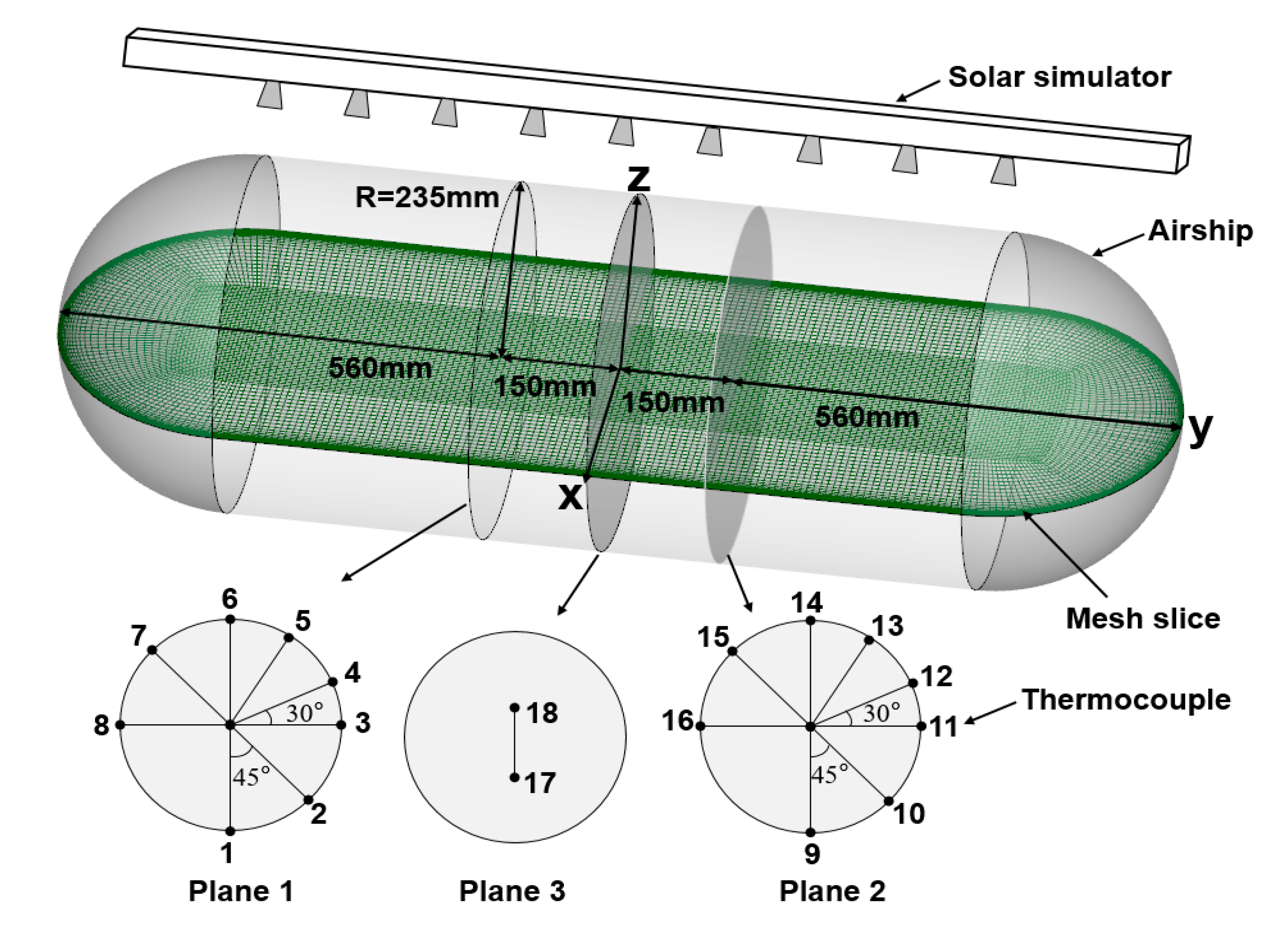
The temperature and flow field in the airship is a result of the interplay among multiple factors including solar radiation, earth reflection, infrared radiation, external forced convection and internal natural convection, which is similar to the thermal environment of a parked car. Therefore, the experimental results of Li et al. [49] were selected for model validation. In their study, the transient thermal behaviors of an airship under different solar radiation were revealed. An airship model with a spherical tank type was built in a closed laboratory. The body was covered with 0.1 mm polyimide film, and shaped by thin metal sheets. Solar irradiation was supplied by a TRM-PD solar simulator and measured by a XLP12-1S-H2 heat flow meter. Eighteen T-type thermocouples were arranged in 18 different locations to obtain the hull and inner gas temperatures. Eight points are located on plane 1 including from point 1 to point 6 and point 8. For plane 2, there are also eight points, from point 9 to point 14 and point 16. Point 18 and point 19 are distributed on plane 3. Plane 1 and plane 2 are symmetrical about plane 3 with 150 mm axial distance. In Figure 2, a full-size computational domain was modeled with the same physical dimensions as the experimental airship. The computational domain was discretized using the structured mesh with five refined inflation layers applied close to the solid surfaces. The grid independence was achieved at 0.2 million mesh elements, as shown in Table 1. To evaluate the CFD approach to model convection-radiation coupled heat transfer in the airship, the hull and inner gas temperatures were compared with experimental data in terms of the accuracy and computational cost. Six turbulence models and four radiation models were included. In each configuration, one turbulence model was combined with or without a radiation model. Finally, thirty CFD cases were obtained totally.
The hull material is polyimide film with thermal conductivity λ = 0.32 w / ( m · K ) . The total solar absorptivity of the external surface is 0.45 with a 0.81 absorptivity in the infrared spectrum. The coupled solver with pseudo-transient relaxation was applied for the solution of the momentum, energy, and turbulence equations. The total calculation adopted 600 s according to the experimental sampling time.
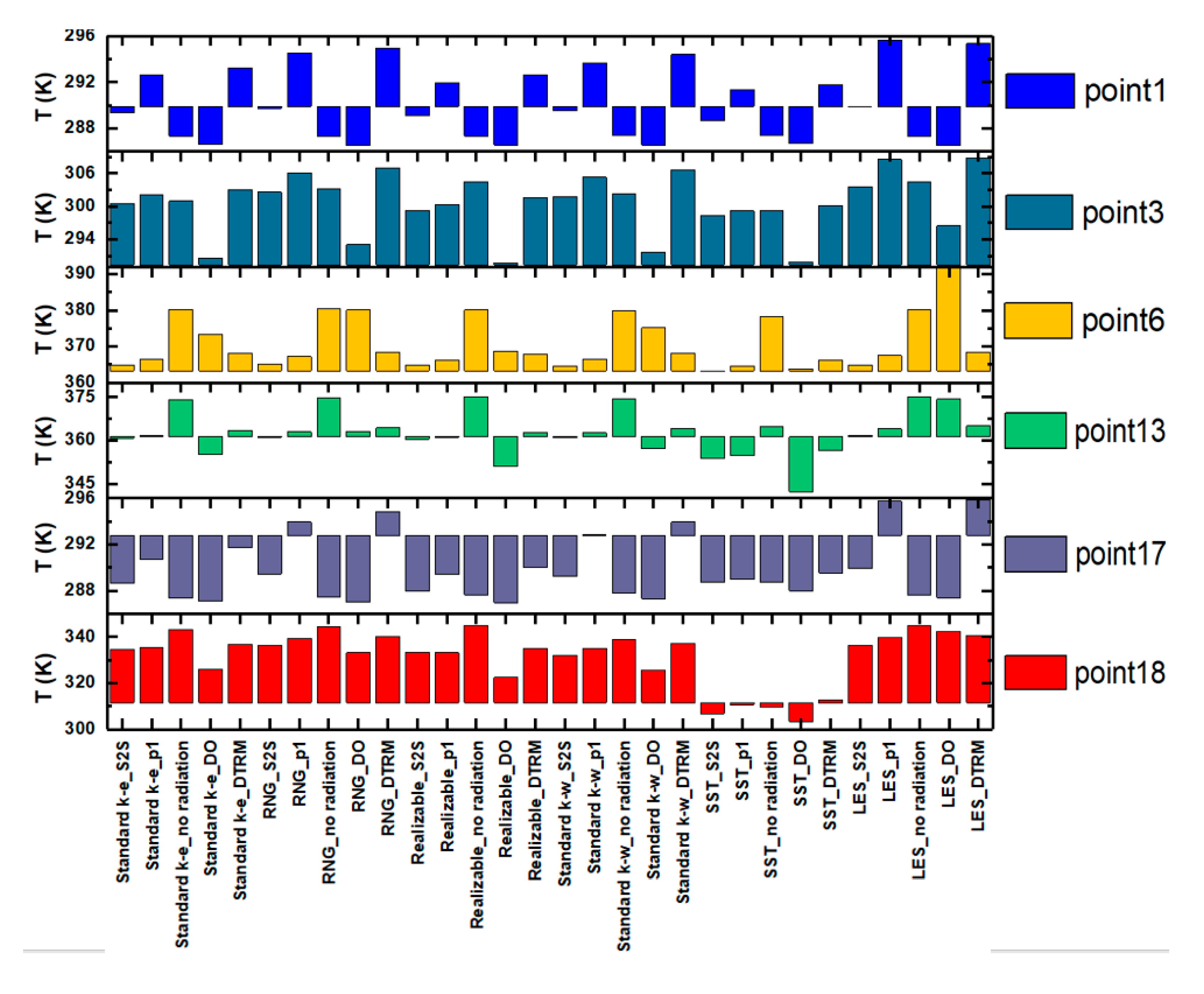
The results of 30 designed test trips with different combinations of radiation and turbulence models are obtained. Except for the air temperature measured at point 17 and 18, the rest are measured at the airship surface. Since the solar simulator is installed above the airship and keeps both axes parallel, the temperature distributions on plane 1 and 2 are basically the same. The temperature of six locations including point 1, point 3, point 6, point 17 and point 18 are shown in Figure 3. The measured data at each point is selected as the benchmark. The temperature of the measuring point closer to the light source is higher. Among them, the temperature at point 6 is the highest, reaching more than 90 °C, from where the temperature drops along with the body surface. Due to the shelter of the airship, point 1 is not directly exposed to the sunlight, resulting in a similar temperature as that of the surroundings with 16.7 °C.
To evaluate the performance of model combinations, a method called the total temperature error is proposed to assess the accuracy of numerical simulations. The total temperature error is calculated according to Equation (11). In addition, the computational cost is obtained according to the CPU calculation time when using a computer with an AMD Ryzen 7 1700X, 3.40 GHz CPU, 32 GB of RAM and 8 compute nodes.
T E r r o r ( % ) = i = 1 18 | T i s i m u l a t e d T i m e a s u r e d | T i m e a s u r e d × 100 %
where T i s i m u l a t e d is the simulated temperature of the i t h point, T i m e a s u r e d is the measured temperature of the i t h point. In the experiment, 18 points were measured totally.
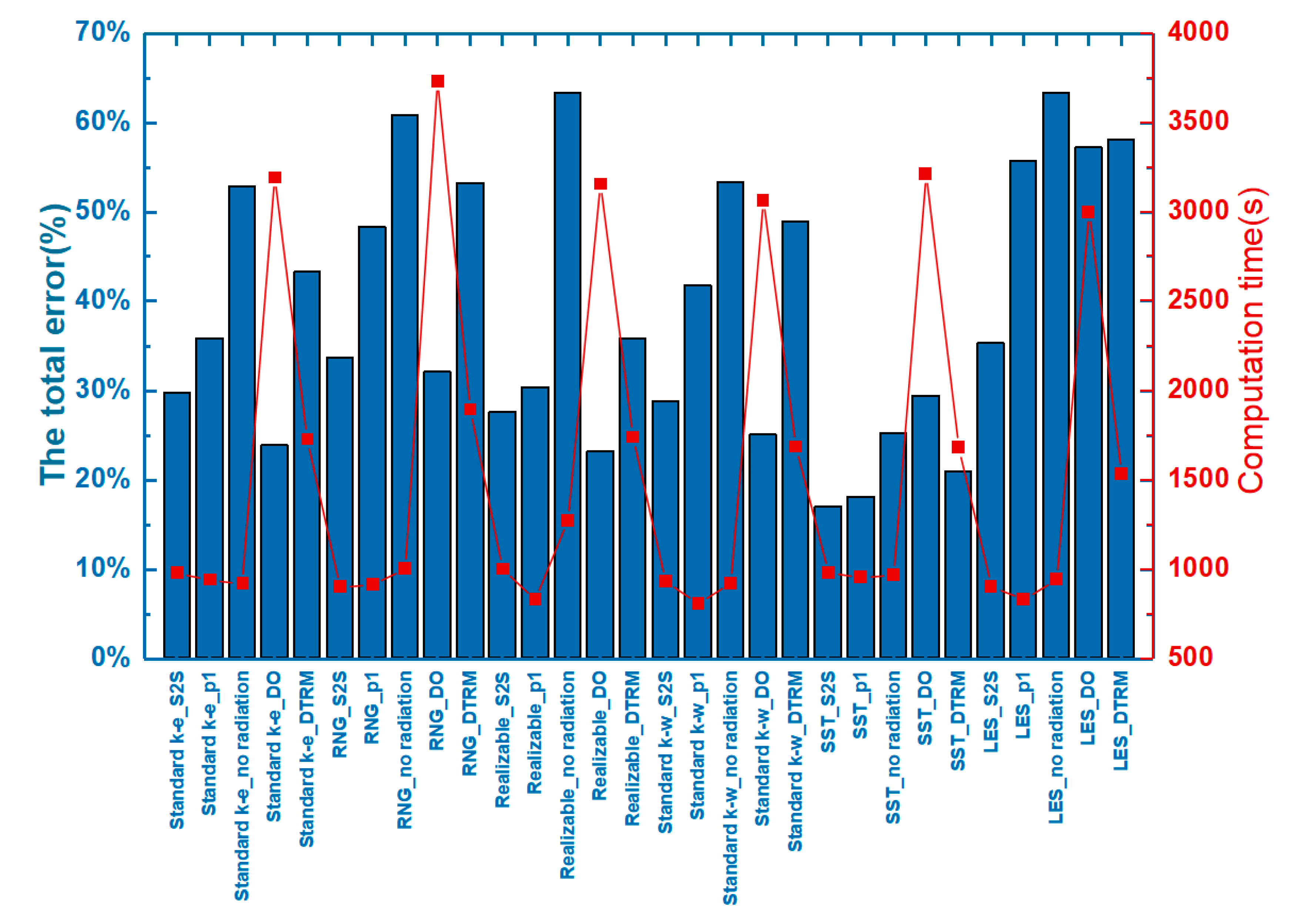
In Figure 4, comparing the temperature errors with and without radiation, the predicted air and solid surface temperature profiles agree better with the experimental results when the effects of thermal radiation are accounted for in the numerical investigation. On the contrary, the total error when ignoring the surface radiation may be twice that when including the surface radiation. When the turbulence model is fixed and combined with different radiation models, it is found that the S2S and DO models perform best, while the DTRM model has the lowest accuracy. Among all turbulence models, the standard k-ω and SST k-ω models have very close accuracies to predict the temperature profiles. The SST k-ω model has a clear advantage in predicting accuracy compared to the LES model; it works the best for the high Rayleigh number buoyancy-driven flow [50]. Figure 4 reveals an M-shape trend of the calculation time according to the order of the combined model. The radiation model has a more significant impact on computation time than the turbulence model. The S2S and P1 radiation models require much less computation time than the DO model, although some small disparities exist but still are comparable. The DTRM is not compatible with parallel processing, so it will consume more time to model radiative heat transfer. The above model validation and comparison suggest that the SST k-ω and S2S model are the best choices to predict the in-vehicle thermal environment under solar radiation. Some existing studies [51] also show that the SST k-ω model performs slightly better than the RNG k-ε model when simulating convection-radiation coupled heat transfer.
To validate the theoretical correlation between the ER and surface temperature, some experimental results in the previous literature were used. Table 2 displays the measured emission rates of five pollutants from the car mat under three varied temperatures and total volatile organic compounds (TVOC) from PBS-C at five different temperatures. The detailed experimental description can be found in references [52,53].
The unit of ER for the volatile organic compounds (VOCs) and total volatile organic compounds (TVOC) is μ g · m 2 · h 1 and mg · m 2 · h 1 , respectively.
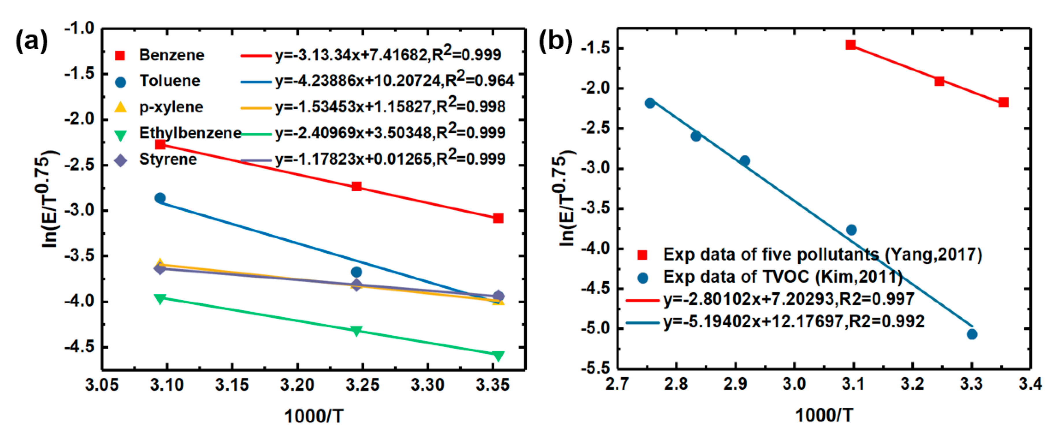
The linear curve fittings are illustrated in Figure 5. All R 2 are greater than 0.95, indicating a satisfactory correlation between the VOCs emission rate and temperature proposed in Equation (9). In the follow-up study, the little impact of existing in-air VOCs on the emission rate is ignored during the emission period [54]. Moreover, the materials maintain their original appearance and properties without any bake out treatment, which indicates abundant VOCs to be volatilized in a quasi-steady state. Besides, the effect of relative humidity on the emission factor is ignored because of the constant relative humidity in that environment [35].

3. In-Vehicle VOCs Distribution Considering Solar Radiation

3.1. Vehicle Computational Model

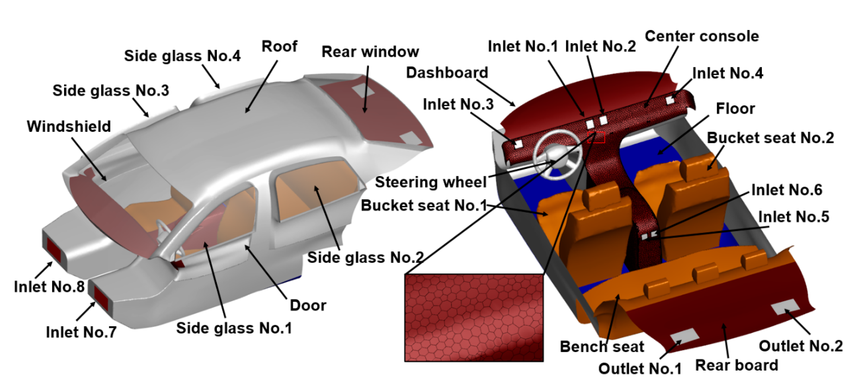
Figure 6 presents the vehicle model established referring to the original data of a hatchback, in which the engine and luggage compartment were ignored. In addition, some interior components including safety belts, electrical equipment and console details were neglected due to the fewer effects on airflow. The details of the dimension are shown in Table 3. The passenger compartment was designed with eight air conditioning inlets and two outlets. Four inlets are located on the center console. Among them, No.1 and No.2 are, respectively, located on the middle, facing the gap between the two bucket seats. No.3 and No.4 are located on the sides. No.5 and No.6 are, respectively, arranged in the feet space of the driver and passenger. No.7 and No.8 are located on the armrest box, facing the bench seat. The air outlets No.1 and No.2 are located on the rear board. No additional airflow inlet and outlet are included anymore under the well-sealed assumption. The vehicle computational domain was discretized using unstructured tetrahedron grids [55]. Inflation layers were used at the interfaces between the air volume and the solids. The case study adopted 3.8 million elements after converting the domain to the polyhedral meshes.

3.2. Boundary Conditions

3.2.1. The Thermal Environment Analysis

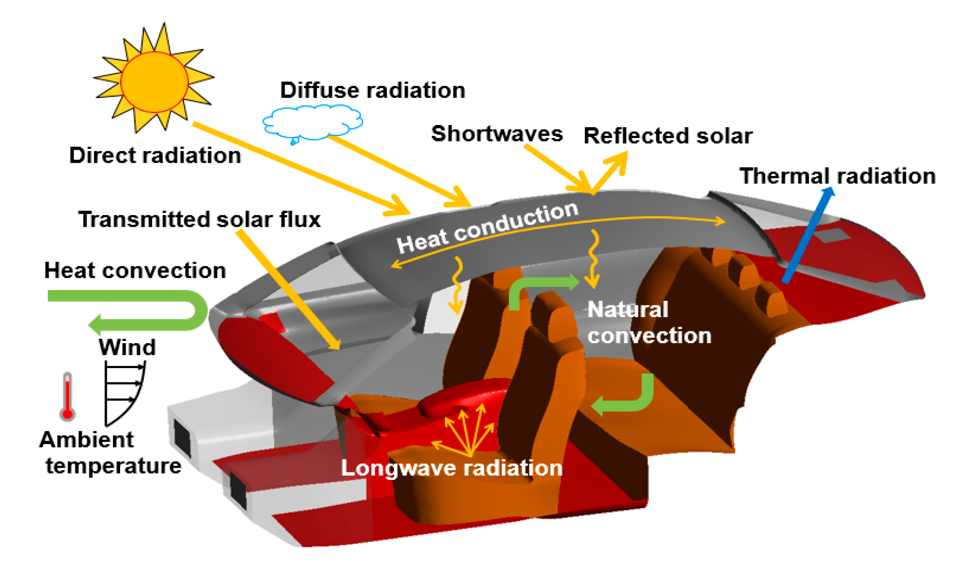
Figure 7 shows the thermal energy transfer for the cabin. External heat enters the cabin through three ways including heat conduction, heat convection and thermal radiation. When the vehicle is parked under the sunlight for a soaking period, some solar radiation enters the passenger compartment passing through the windows, some is reflected by the solid envelope, the rest is absorbed. Solar radiation leads to a considerable thermal load through heating the envelope and interiors. In addition, the cabin exchanges the heat with the external environment through the coupled convection and radiation. Due to the uniform temperature distribution, the airflow cycles are driven by buoyant force, creating the natural convection in the cabin. The scorching air is trapped inside the cabin due to the lack of openings, resulting in the greenhouse effect [56]. In this study, the simulation was based on the city of Hangzhou (118°21′–120°30′ E, 29°11′–30°33′ N), the capital of Zhejiang Province located along Southeast coast of China, characterized by long and hot summers. The ambient conditions were chosen on June 21 (summer solstice). The windshield orientation was to the south.

3.2.2. The Thermal Setup

The cabin enclosure is composed of body structure, door, floor and glass, exposed to outdoor climatic conditions with sun and wind directly; the mixed wall thermal boundary was uniformly applied to the shell. According to the local summer weather condition, the ambient temperature of 38 °C was set as free steam and external radiation temperature for the whole cabin body, except for the driver’s foot space adjacent to the engine cooling water. The appropriate thermal resistance across the wall thickness was imposed according to the wall thickness and material properties. The details are presented in Table 4. Besides, the shell conduction approach was utilized to model conduction in the planar direction of steel body with good thermal conductivity. All solid surfaces were considered stationary walls with No-slip conditions. The convective heat transfer coefficient was calculated based on the empirical formula in Equation (12) [29]. The inlets and outlets of the HVAC system were treated as the wall when the vehicle kept ventilation off.
h = 1.163 ( 4 + 12 v 0.5 )
where v is the wind speed relative to the parked vehicle with 0.2   m / s , h = 10.89   W / m 2 K .

3.2.3. The Radiation Setup

The windshield, side window, and rear window were treated optically as semi-transparent walls; all other surfaces were considered opaque. All surfaces participated in radiation heat transfer. The emissivity of interior surfaces was assumed to be 0.95 [30], and 0.88 for the windows [57]. The optical properties of the cabin surfaces are listed in Table 5.

3.2.4. The Emission Model Setup

Due to the common HVAC operation during driving and brief natural ventilation when getting off, it is reasonable to expect a very low concentration of contaminants left in the cabin. Moreover, the existence of contaminants has no impact on the airflow and concentration dispersion. Under such reasonable assumptions, defining the user-defined source (UDS) equation is computationally less expensive compared to the multi-component Eulerian approach when modeling the gas transport [51]. Therefore, the unsteady variation, convection, diffusion, and generation in the domain were calculated using a UDS coupled with the user-defined functions (UDFs) based on the existing flow parameters.
t ( ρ S ) + · ( ρ S U Γ S ) = 0
where ρ is the density of air, S is a scalar representing the contaminant concentration, Γ is the molecular diffusivity of S .

4. Results and Discussion

Chemical mass balance results demonstrated that carpet and seats are the most important VOCs source inside a new vehicle [58], so the bucket, bench seats and floor were chosen as the conventional VOCs sources in the cabin. Besides, the contaminant emission behavior of the dashboard and rear board were additionally investigated due to their prominent representation of high solar exposure.
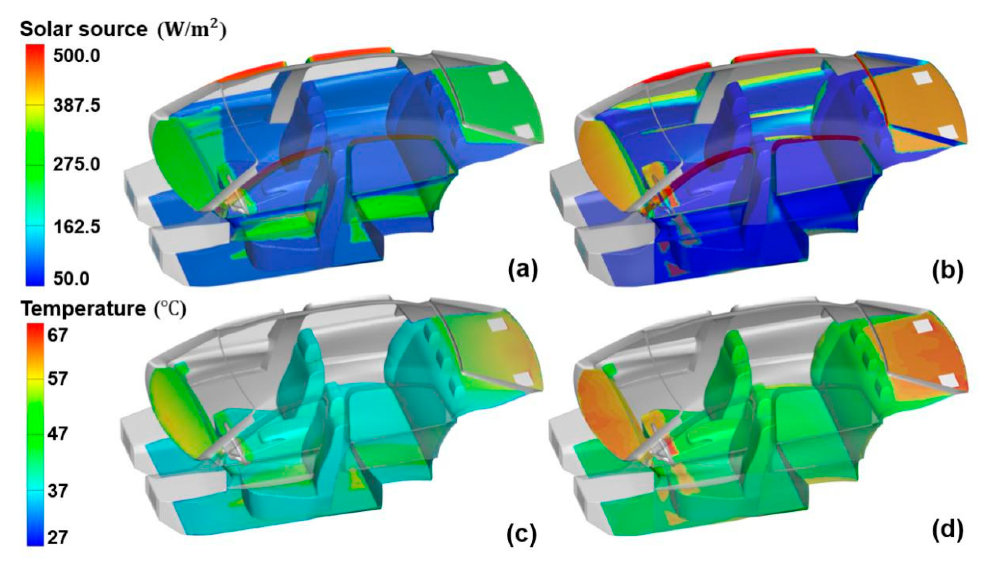
Solar flux and average temperature variations and distributions with respect to soaking process are shown in Figure 8 and Figure 9, respectively. The transmitted solar flux shows a decrease tendency on window No.3 and No.4, whereas with a sustained growth for the other envelope throughout the soaking period. Most direct solar irradiation (over 350 W) enters the cabin through the windshield and rear glass, falling on the dashboard and rear board. Only a small portion of the sun’s rays (below 40 W) passes through the side windows. At noon, the sun moves directly above the vehicle with about 180° solar incidence angle, causing a similar solar load on both side body. In Figure 8b, the surface temperature rises steadily with the increase of solar intensity. The highest average temperature with more than 60 °C occurs at the dashboard and rear board, while the floor has the lowest temperature with about 44 °C. The average temperature of bucket seat No.1 is slightly higher than that of No.2. This is due to the reason that the former receives more solar load from both the windshield and left glass (Figure 9a). The temperature on the two bucket seats tends to be the same at noon because of the comparable sun exposure (Figure 9b). The heat is difficult to transfer around the interior surface by conduction due to low thermal conductivity, exacerbating the thermal imbalance and local overheating [59].
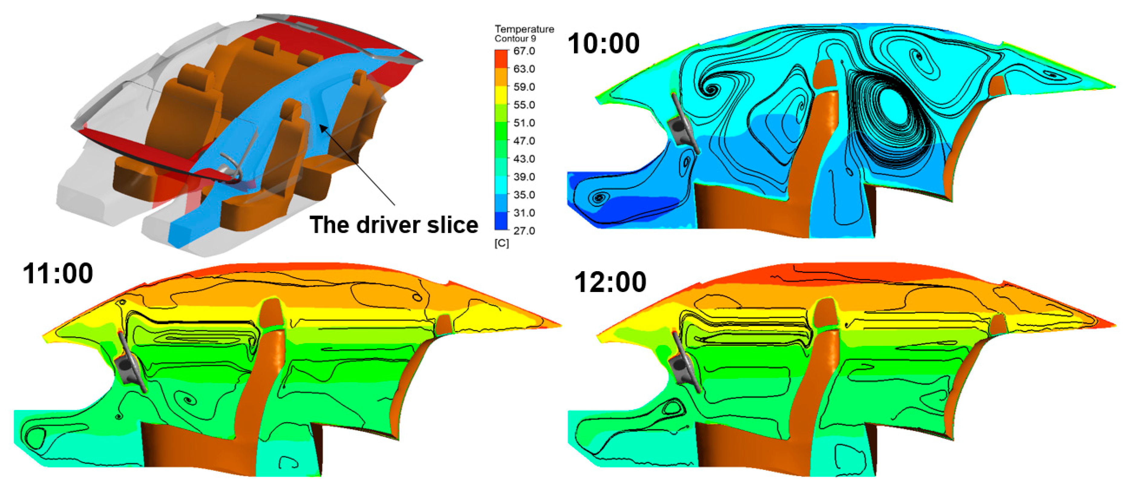
Figure 10 displays the temperature distributions of airflows in the driver plane. The air temperature near the hot interior surface is substantially higher than that which is far away from it; this is because of where the thermal boundary layers exist. In addition, the upper air owns a higher temperature because of the hot air rising and more heat sources. The hotter air gradually develops towards the floor, forming obvious temperature stratification phenomenon. The temperature in the driver’s head position reaches 59 °C. At 10:00 am, the airflow crosses the bucket to the rear compartment, while it turns into a flow recirculation in the located temperature layer at 11:00 am and noon. Our analysis shows that the temperature distribution is primarily affected by solar radiation and airflow itself. Due to the heat exchange and direct solar heating, the temperature rises as much as 30 °C for direct exposed cabin surfaces and 10 °C for shaded ones, respectively, which supports the claim that solar radiation is a necessity in the thermal environment simulation.
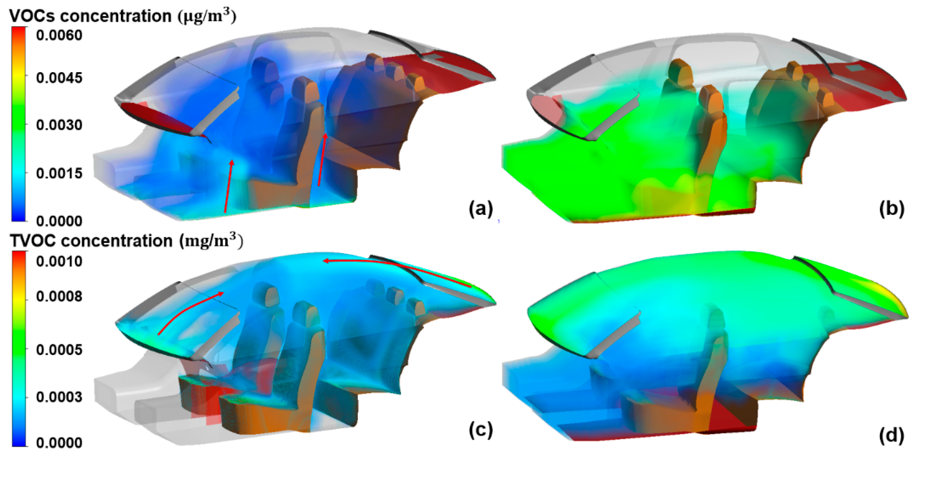
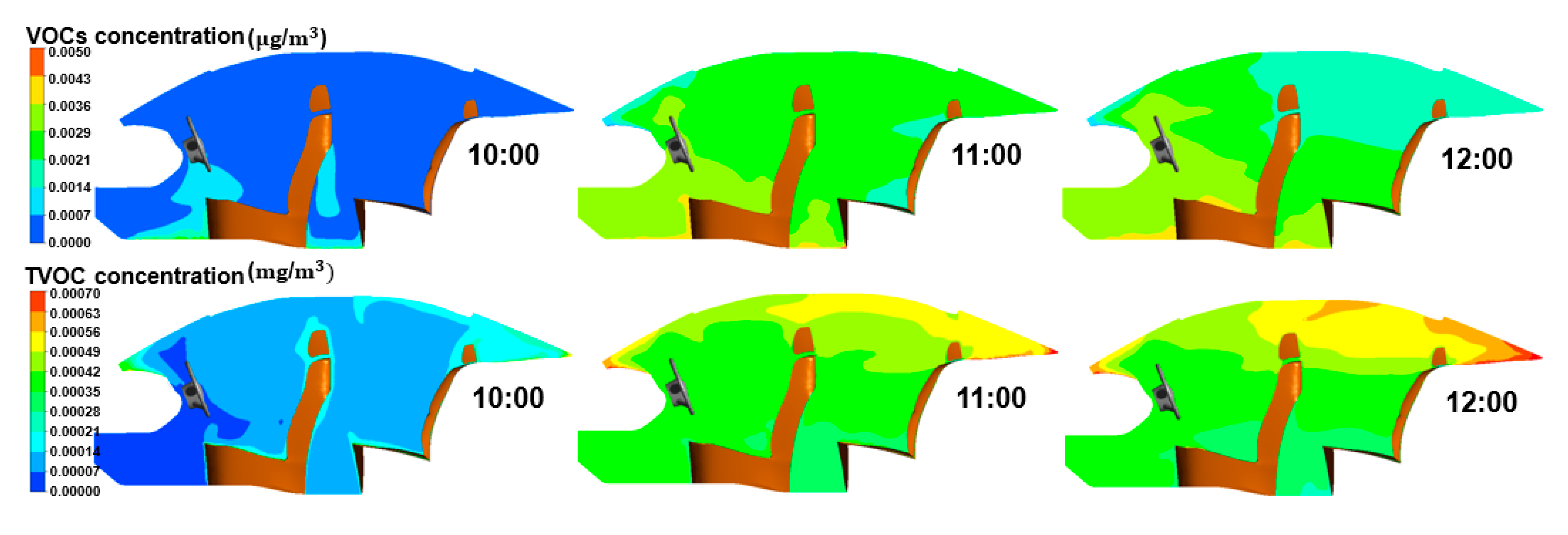
Figure 11 shows the VOCs distributions in the whole cabin at 10:00 am and noon, respectively. And the driver plane was selected in the compartment to analyze the VOCs distributions under solar radiation in Figure 12. It is clearly noticed that the VOCs concentration at the hotter contaminant source is remarkably larger due to the strong dependence between the VOCs emission and the surface temperature. The dashboard and rear board are exposed to the strongest sunlight uniformly, therefore releasing more TVOC at the per unit area. The VOCs emission from the higher temperature area at the carpet increases approximately five-fold compared to the unexposed region. From the view of time, the concentration is about 3–4 times higher at noon than 10:00 am. Besides, the paths of concentration distribution and dispersion are significantly different in the four cases. A remarkable pollutant plume above the hotter surfaces is observed in Figure 12, which confirms that the near-wall thermal buoyancy flows are captured by the adopted turbulence and radiation models. The higher VOCs concentration distributes below the driver’s knees, which is difficult to diffuse above the dashboard and rear board by natural convection (Figure 11a,b). Most TVOC is concentrated on the driver’s head and above. As the concentration increases, a small amount of TVOC moves towards the floor under the driving of concentration difference. On the roof, the pollutants released from the dashboard and rear board tend to form a bridge of high concentration contaminants (Figure 11c,d). All pollutants gather near the surface sources and diffuse throughout the surroundings without ventilation. It demonstrates that thermal buoyancy and natural convection play an important role in dissipating pollutants from the contaminant source to the adjacent air in the enclosed environment.
Table 6 lists the amount of pollutants released by materials from 10:00 am to noon, which was calculated based on the Equation (10). There is a total of 35.08 μ g VOCs emitted from carpet and 19 mg TVOC released from other interiors, which far exceeds the national standards of many countries. The seats become the largest source of pollutants due to the larger surface area. Moreover, as illustrated in Figure 10, above the seats are the places where pollutants are most likely to accumulate. It will pose a great threat to health if the level of pollutant exposure cannot be mitigated effectively by natural ventilation or HVAC systems when drivers and passengers re-enter the car.

5. Conclusions

The in-vehicle VOCs exposure is a public health concern worldwide. This study explored the thermal environment of an in-vehicle cabin under solar radiation and provided an early effort to quantify the spatial distribution of VOCs released from interior surfaces. In this study, the in-cabin thermal environment was simulated by considering in-cabin natural convection-conduction coupled with solar radiation. The performance of different combinations of turbulence and radiation models was validated with measured temperature data in a reduced-scale airplane cabin. Combining the SST k-ω turbulence model with a surface-to-surface radiation model (S2S) performed best in terms of computational accuracy among 30 different combinations, including turbulence models such as the standard k-ε, RNG k-ε, realizable k-ε, standard k-ω, SST k-ω and LES model and radiation models such as the P-1, S2S, DO, DTRM model. Our findings suggest that solar radiation plays a critical role in determining the temperature distribution in the cabin, which can increase as much as 30 °C for direct exposed cabin surfaces and 10 °C for shaded ones. The maximum average temperature was observed over 60 °C on the dashboard and rear board that were exposed the direct sunlight. The lowest temperature was found on the cabin floor at 44 °C. Such a high cabin temperature profile considerably lowers the thermal comfort and promotes VOCs emissions due to a strong temperature dependence. The dispersion of VOCs strongly depended on the local emission rate and airflows. The dashboard and rear board were shown to have a larger emission rate than that of the seats and floor because of the higher surface temperature. The VOC plume from the seats rose upward towards the ceiling, whereas the VOCs from the floor stayed below the seats. From the 2-h simulation period from 10:00 am to noon, there was a total of 35.08 μ g VOCs and 19.02 mg TVOC accumulated throughout the cabin. With increasing attention to the cabin environment and the health of drivers and passengers, the findings, such as modeled spatial distributions of VOCs, provide automakers with an important design guide that could improve the current ventilation design for the summer time.

Author Contributions

H.L.: conceptualization, methodology, and writing—original draft preparation. Z.T.: methodology, project administration and writing—review and editing. All authors have read and agreed to the published version of the manuscript.

Funding

This work was supported by the National Natural Science Foundation of China (51708493); Zhejiang Provincial Natural Science Foundation (LR19E050002); the Zhejiang Province Key Science and Technology Project (2020C01111);

Conflicts of Interest

The authors declare no conflict of interest.

Nomenclature

q r Radiation heat flux
a Absorption coefficient
σ s Scattering coefficient
C Linear-anisotropic phase function coefficient
G Incident radiation
σ Stefan–Boltzmann constant, 5.672 × 10 8 W / m 2 K 4
q out , k Energy flux leaving the surface
q in , k Incoming energy flux on the surface
ε k Surface emissivity
ρ k Surface reflectivity
T Gas local temperature, K
T k Surface temperature, K
I Radiation intensity
r Position vector
s Direction vector
s Scattering direction vector
n Refractive index
Φ Phase function
Ω Solid angle
E ( t ) Emission rate
D m Diffusion coefficient
C 0 Initial emittable concentration
δ Material thickness, mm
t Emission time, s
M Contaminant quality
A Surface area, m 2
t s Release start time
t e Release end time
T Error Temperature error
T isimulated Simulated temperature of the i th point, K
T imeasured Measured temperature of the i th point, K
λ Thermal conductivity, W · m 1 · K 1
c p Specific heat, J · kg 1 · K 1
ρ Material Density, kg · m 3
h Convective heat transfer coefficient, W / m 2 K
v Wind speed, m / s
ρ air Air density, kg · m 3
S Scalar
Γ Molecular diffusivity, m 2 / s

References

  1. Tong, Z.; Li, Y.; Westerdahl, D.; Adamkiewicz, G.; Spengler, J.D. Exploring the effects of ventilation practices in mitigating in-vehicle exposure to traffic-related air pollutants in China. Environ. Int. 2019, 127, 773–784. [Google Scholar] [CrossRef] [PubMed]
  2. Tong, Z.; Li, Y.; Westerdahl, D.; Freeman, R.B. The impact of air filtration units on primary school students’ indoor exposure to particulate matter in China. Environ. Pollut. 2020, 115107. [Google Scholar] [CrossRef]
  3. Tong, Z.; Whitlow, T.H.; MacRae, P.F.; Landers, A.J.; Harada, Y. Quantifying the effect of vegetation on near-road air quality using brief campaigns. Environ Pollut 2015, 201, 141–149. [Google Scholar] [CrossRef]
  4. Tong, Z.; Chen, Y.; Malkawi, A.; Adamkiewicz, G.; Spengler, J.D. Quantifying the impact of traffic-related air pollution on the indoor air quality of a naturally ventilated building. Environ. Int. 2016, 89, 138–146. [Google Scholar] [CrossRef]
  5. Zhang, G.; Li, T.; Luo, M.; Liu, J.; Liu, Z.; Bai, Y. Air pollution in the microenvironment of parked new cars. Build. Environ. 2008, 43, 315–319. [Google Scholar] [CrossRef]
  6. Brodzik, K.; Faber, J.; Łomankiewicz, D.; Gołda-Kopek, A. In-vehicle VOCs composition of unconditioned, newly produced cars. J. Environ. Sci. 2014, 26, 1052–1061. [Google Scholar] [CrossRef]
  7. You, K.; Ge, Y.; Hu, B.; Ning, Z.; Zhao, S.; Zhang, Y.; Xie, P. Measurement of in-vehicle volatile organic compounds under static conditions. J. Environ. Sci. 2007, 19, 1208–1213. [Google Scholar] [CrossRef]
  8. Khanchi, A.; Hebbern, C.A.; Zhu, J.; Cakmak, S. Exposure to volatile organic compounds and associated health risks in windsor, Canada. Atmos. Environ. 2015, 120, 152–159. [Google Scholar] [CrossRef]
  9. Borecki, M.; Prus, P.; Korwin-Pawlowski, M.L. Capillary Sensor with Disposable Optrode for Diesel Fuel Quality Testing. Sensors 2019, 19, 1980. [Google Scholar] [CrossRef] [Green Version]
  10. Zulauf, N.; Dröge, J.; Klingelhöfer, D.; Braun, M.; Oremek, G.M.; Groneberg, D.A. Indoor Air Pollution in Cars: An Update on Novel Insights. Int. J. Environ. Res. Public Health 2019, 16, 2441. [Google Scholar] [CrossRef] [Green Version]
  11. World Health Organization. WHO Guidelines for Indoor Air Quality: Selected Pollutants. Available online: https://www.euro.who.int/_data/assets/pdf_file/0009/128169/e94535.pdf (accessed on 30 June 2020).
  12. Xu, B.; Wu, Y.; Yu, G.; Wu, S.; Wu, X.; Zhu, S.; Tao, L. Investigation of volatile organic compounds exposure inside vehicle cabins in China. Atmos. Pollut. Res. 2016, 7, 215–220. [Google Scholar] [CrossRef]
  13. Faber, J.; Brodzik, K.; Da-Kopek, A.G.; Lomankiewicz, D. Benzene, toluene and xylenes levels in new and used vehicles of the same model. J. Environ. Sci. 2013, 25, 2324–2330. [Google Scholar] [CrossRef]
  14. Yang, X.; Srebric, J.; Li, X.; He, G. Performance of three air distribution systems in VOC removal from an area source. Build. Environ. 2004, 39, 1289–1299. [Google Scholar] [CrossRef]
  15. Kim, K.-H.; Szulejko, J.E.; Jo, H.-J.; Lee, M.-H.; Kim, Y.-H.; Kwon, E.; Ma, C.-J.; Kumar, P. Measurements of major VOCs released into the closed cabin environment of different automobiles under various engine and ventilation scenarios. Environ. Pollut. 2016, 215, 340–346. [Google Scholar] [CrossRef] [PubMed]
  16. Cao, X.; Yao, Z.; Shen, X.; Yu, Y.; Xi, J. On-road emission characteristics of VOCs from light-duty gasoline vehicles in Beijing, China. Atmos. Environ. 2015, 124, 146–155. [Google Scholar] [CrossRef]
  17. Wiglusz, R.; Sitko, E.; Nikel, G.; Jarnuszkiewicz, I.; Igielska, B. The effect of temperature on the emission of formaldehyde and volatile organic compounds (VOCs) from laminate flooring—Case study. Build. Environ. 2002, 37, 41–44. [Google Scholar] [CrossRef]
  18. Xiong, J.; Zhang, Y. Impact of temperature on the initial emittable concentration of formaldehyde in building materials: Experimental observation. Indoor Air 2010, 20, 523–529. [Google Scholar] [CrossRef] [PubMed]
  19. Xiong, J.; Zhang, P.; Huang, S.; Zhang, Y. Comprehensive influence of environmental factors on the emission rate of formaldehyde and VOCs in building materials: Correlation development and exposure assessment. Environ. Res. 2016, 151, 734–741. [Google Scholar] [CrossRef]
  20. Yoshida, T.; Matsunaga, I. A case study on identification of airborne organic compounds and time courses of their concentrations in the cabin of a new car for private use. Environ. Int. 2006, 32, 58–79. [Google Scholar] [CrossRef]
  21. Geiss, O.; Tirendi, S.; Barrero-Moreno, J.; Kotzias, D. Investigation of volatile organic compounds and phthalates present in the cabin air of used private cars. Environ. Int. 2009, 35, 1188–1195. [Google Scholar] [CrossRef]
  22. Faber, J.; Brodzik, K.; Łomankiewicz, D.; Gołda-Kopek, A.; Nowak, J.; Świątek, A. Temperature influence on air quality inside cabin of conditioned car. Siln. Spalinowe 2012, 51, 49–56. [Google Scholar]
  23. Chen, X.; Feng, L.; Luo, H.; Cheng, H. Analyses on influencing factors of airborne VOC S pollution in taxi cabins. Environ. Sci. Pollut. Res. 2014, 21, 12868–12882. [Google Scholar] [CrossRef] [PubMed]
  24. Xiong, J.; Yang, T.; Tan, J.; Li, L.; Ge, Y. Characterization of VOC emission from materials in vehicular environment at varied temperatures: Correlation development and validation. PLoS ONE 2015, 10, e0140081. [Google Scholar] [CrossRef] [PubMed]
  25. Huang, W.; Lv, M.; Yang, X. Long-term volatile organic compound emission rates in a new electric vehicle: Influence of temperature and vehicle age. Build. Environ. 2020, 168, 106465. [Google Scholar] [CrossRef]
  26. Tong, Z.; Liu, H.; Tong, S.; Xu, J. Inverse Design for Thermal Environment and Energy Consumption of Vehicular Cabins with PSO–CFD Method. In International Conference on Man-Machine-Environment System Engineering; Springer Singapore: Singapore, 2020. [Google Scholar]
  27. Tong, Z.; Li, Y. Real-Time Reconstruction of Contaminant Dispersion from Sparse Sensor Observations with Gappy POD Method. Energies 2020, 13, 1956. [Google Scholar] [CrossRef] [Green Version]
  28. Chen, Y.; Tong, Z.; Zheng, Y.; Samuelson, H.; Norford, L. Transfer learning with deep neural networks for model predictive control of HVAC and natural ventilation in smart buildings. J. Clean Prod. 2020, 254, 119866. [Google Scholar] [CrossRef]
  29. Wu, J.; Jiang, F.; Song, H.; Liu, C.; Lu, B. Analysis and validation of transient thermal model for automobile cabin. Appl. Therm. Eng. 2017, 122, 91–102. [Google Scholar] [CrossRef]
  30. Lee, J.W.; Jang, E.Y.; Lee, S.H.; Ryou, H.S.; Choi, S.; Kim, Y.; Brodzik, K. Influence of the spectral solar radiation on the air flow and temperature distributions in a passenger compartment. Int. J. Therm. Sci. 2014, 75, 36–44. [Google Scholar] [CrossRef]
  31. Mao, Y.; Wang, J.; Li, J. Experimental and numerical study of air flow and temperature variations in an electric vehicle cabin during cooling and heating. Appl. Therm. Eng. 2018, 137, 356–367. [Google Scholar] [CrossRef]
  32. Torregrosa-Jaime, B.; Bjurling, F.; Corberán, J.M.; Di Sciullo, F.; Payá, J. Transient thermal model of a vehicle’s cabin validated under variable ambient conditions. Appl. Therm. Eng. 2015, 75, 45–53. [Google Scholar] [CrossRef] [Green Version]
  33. Zhang, H.; Dai, L.; Xu, G.; Li, Y.; Chen, W.; Tao, W.-Q. Studies of air-flow and temperature fields inside a passenger compartment for improving thermal comfort and saving energy. Part I: Test/numerical model and validation. Appl. Therm. Eng. 2009, 29, 2022–2027. [Google Scholar] [CrossRef]
  34. Moon, J.H.; Jin, W.L.; Chan, H.J.; Lee, S.H. Thermal comfort analysis in a passenger compartment considering the solar radiation effect. Int. J. Therm. Sci. 2016, 107, 77–88. [Google Scholar] [CrossRef]
  35. Zhou, X.; Lai, D.; Chen, Q. Experimental investigation of thermal comfort in a passenger car under driving conditions. Build. Environ. 2019, 149, 109–119. [Google Scholar] [CrossRef]
  36. Marcos, D.; Pino, F.J.; Bordons, C.; Guerra, J.J. The development and validation of a thermal model for the cabin of a vehicle. Appl. Therm. Eng. 2014, 66, 646–656. [Google Scholar] [CrossRef]
  37. Grundstein, A.; Meentemeyer, V.; Dowd, J. Maximum vehicle cabin temperatures under different meteorological conditions. Int. J. Biometeorol. 2009, 53, 255–261. [Google Scholar] [CrossRef] [PubMed]
  38. Pan, H.; Qi, L.; Zhang, X.; Zhang, Z.; Salman, W.; Yuan, Y.; Wang, C. A portable renewable solar energy-powered cooling system based on wireless power transfer for a vehicle cabin. Appl. Energy 2017, 195, 334–343. [Google Scholar] [CrossRef]
  39. Soulios, V.; Loonen, R.; Metavitsiadis, V.; Hensen, J. Computational performance analysis of overheating mitigation measures in parked vehicles. Appl. Energy 2018, 231, 635–644. [Google Scholar] [CrossRef]
  40. Al-Kayiem, H.H.; Sidik, M.F.B.M.; Munusammy, Y.R.A.L. Study on the Thermal Accumulation and Distribution Inside a Parked Car Cabin. Am. J. Appl. Sci. 2010, 7, 784–789. [Google Scholar] [CrossRef] [Green Version]
  41. Borecki, M.; Gȩca, M.; Duk, M.; Korwin-Pawlowski, M.L. Miniature gas sensors heads and gas sensing devices for environmental working conditions—A review. J. Electron. Commun. Eng. Res. 2017, 1, 1–11. [Google Scholar]
  42. Zhai, Z.J.; Zhang, Z.; Zhang, W.; Chen, Q.Y. Evaluation of various turbulence models in predicting airflow and turbulence in enclosed environments by CFD: Part 1–Summary of prevalent turbulence models. Hvac&R Res. 2007, 13, 853–870. [Google Scholar]
  43. Hussain, S.; Oosthuizen, P.H.; Kalendar, A. Evaluation of various turbulence models for the prediction of the airflow and temperature distributions in atria. Energy Build. 2011, 43, 18–28. [Google Scholar] [CrossRef]
  44. Li, X.; Tu, J. Evaluation of the eddy viscosity turbulence models for the simulation of convection–radiation coupled heat transfer in indoor environment. Energy Build. 2019, 184, 8–18. [Google Scholar] [CrossRef]
  45. ASHRAE Handbook-Fundamentals (SI Edition). American society of Heating, Refrigerating and Air-Conditioning Engineers: Atlanta, GA, USA, 2009. Available online: http://shop.iccsafe.org/media/wysiwyg/material/8950P217-toc.pdf (accessed on 7 July 2020).
  46. Xiong, J.; Wei, W.; Huang, S.; Zhang, Y. Association between the emission rate and temperature for chemical pollutants in building materials: General correlation and understanding. Environ. Sci. Technol. 2013, 47, 8540–8547. [Google Scholar] [CrossRef]
  47. Huang, S.; Xiong, J.; Zhang, Y. Impact of temperature on the ratio of initial emittable concentration to total concentration for formaldehyde in building materials: Theoretical correlation and validation. Environ. Sci. Technol. 2015, 49, 1537–1544. [Google Scholar] [CrossRef] [PubMed]
  48. Deng, Q.; Yang, X.; Zhang, J. Study on a new correlation between diffusion coefficient and temperature in porous building materials. Atmos. Environ. 2009, 43, 2080–2083. [Google Scholar] [CrossRef]
  49. Li, D.F.; Xia, X.L.; Sun, C. Experimental investigation of transient thermal behavior of an airship under different solar radiation and airflow conditions. Adv. Space Res. 2014, 53, 862–869. [Google Scholar] [CrossRef]
  50. Zhang, Z.; Zhang, W.; Zhai, Z.J.; Chen, Q.Y. Evaluation of various turbulence models in predicting airflow and turbulence in enclosed environments by CFD: Part 2—Comparison with experimental data from literature. Hvac& R Res. 2007, 13, 871–886. [Google Scholar]
  51. Li, X.; Yan, Y.; Tu, J. Effects of surface radiation on gaseous contaminants emission and dispersion in indoor environment—A numerical study. Int. J. Heat Mass Transf. 2019, 131, 854–862. [Google Scholar] [CrossRef]
  52. Yang, T.; Zhang, P.; Xu, B.; Xiong, J. Predicting VOC emissions from materials in vehicle cabins: Determination of the key parameters and the influence of environmental factors. Int. J. Heat Mass Transf. 2017, 110, 671–679. [Google Scholar] [CrossRef]
  53. Kim, K.W.; Lee, B.H.; Kim, S.; Kim, H.J.; Yun, J.H.; Yoo, S.E.; Sohn, J.R. Reduction of VOC emission from natural flours filled biodegradable bio-composites for automobile interior. J. Hazard Mater. 2011, 187, 37–43. [Google Scholar] [CrossRef]
  54. Qian, K.; Zhang, Y.; Little, J.C.; Wang, X. Dimensionless correlations to predict VOC emissions from dry building materials. Atmos. Environ. 2007, 41, 352–359. [Google Scholar] [CrossRef]
  55. ANSYS®. Academic Research Release 17.2, Help System, Coupled Field Analysis Guide; ANSYS, Inc.: Canonsburg, PA, USA, 2017. [Google Scholar]
  56. Lahimer, A.; Alghoul, M.; Sopian, K.; Khrit, N. Potential of solar reflective cover on regulating the car cabin conditions and fuel consumption. Appl. Therm. Eng. 2018, 143, 59–71. [Google Scholar] [CrossRef]
  57. Mezrhab, A.; Bouzidi, M. Computation of thermal comfort inside a passenger car compartment. Appl. Therm. Eng. 2006, 26, 1697–1704. [Google Scholar] [CrossRef]
  58. Liang, B.; Yu, X.; Mi, H.; Liu, D.; Huang, Q.; Tian, M. Health risk assessment and source apportionment of VOCs inside new vehicle cabins: A case study from Chongqing, China. Atmos. Pollut. Res. 2019, 10, 1677–1684. [Google Scholar] [CrossRef]
  59. Wu, W.; Yoon, N.; Tong, Z.; Chen, Y.; Lv, Y.; Ærenlund, T.; Benner, J. Diffuse ceiling ventilation for buildings: A review of fundamental theories and research methodologies. J. Clean Prod. 2019, 211, 1600–1619. [Google Scholar] [CrossRef]
Figure 1. The framework of our methodology.
Sustainability 12 05526 g001
Figure 2. The airship computational domain according to [49].
Sustainability 12 05526 g002
Figure 3. Comparisons of the experimental and numerical temperature T ( K ) in the closed airship. Simulation data floats up and down based on experimental data from [49].
Sustainability 12 05526 g003
Figure 4. The total temperature error and computation time of 30 cases.
Sustainability 12 05526 g004
Figure 5. (a) The relationship between five VOCs emissions and temperature according to the experimental data [52]; (b) The relationship between TVOC emission and temperature according to the experimental data [53].
Sustainability 12 05526 g005
Figure 6. The computational model of the passenger compartment.
Sustainability 12 05526 g006
Figure 7. Heat transfer between the surface and its surroundings in the cabin.
Sustainability 12 05526 g007
Figure 8. The solar flux (a) and temperature (b) variations from 10:00 am to noon.
Sustainability 12 05526 g008
Figure 9. The solar heat distributions at 10:00 am (a) and noon (b); The temperature distributions at 10:00 am (c) and noon (d).
Sustainability 12 05526 g009
Figure 10. Temperature distributions of airflows with respect to the three time cases at driver plane.
Sustainability 12 05526 g010
Figure 11. VOCs concentration emitted from carpet at 10:00 am (a) and noon (b); TVOC released from dashboard, rear board and seats at 10:00 am (c) and noon (d).
Sustainability 12 05526 g011
Figure 12. The pollutant distributions on the driver plane from 10:00 am to noon.
Sustainability 12 05526 g012
Table 1. The grid independence test of the temperature profile at point 18.
Type Cell NumberThe Temperature of Point 18 (K)
Grid 15640378.39
Grid 29728378.62
Grid 335685381.75
Grid 4108547382.31
Grid 5207100382.34
Table 2. The emission rate (ER) of pollutants from in-vehicle materials under varied temperature conditions.
TypeER at 25 °CER at 35 °CER at 50 °C
VOCsBenzene1.0491.5172.472
Toluene2.4720.5951.376
P-xylene0.4230.5170.659
Ethylbenzene0.2350.3150.459
Styrene0.4470.5170.635
TVOCER at 35°CER at 50 °CER at 70 °CER at 80 °CER at 90 °C
0.3931.8364.4596.0339.311
Table 3. The dimensions of the vehicle model.
PartsDimensionUnit
body3100*1600*1230(L*W*H)(mm)
windshield0.864 m 2
rear window0.787 m 2
side window 1 and 30.224 m 2
side window 2 and 40.266 m 2
cabin volume2.716 m 3
Table 4. The material parameters and optical properties of the main parts.
PartsMaterialDensity
ρ / ( kg · m 3 )
Thermal Conductivity
λ / ( W · m 1 · K 1 )
Specific Heat
c p / ( J · kg 1 · K 1 )
Thickness
δ/mm
vehicle bodysteel8030.00100.04448.835.00
Dashboard
rear board
PBS1260.002.701480.605.00
center console1.50
seats15.00
floorcarpet1601.850.291485.385.00
windowsglass2529.581.17754.045.00
Table 5. The optical properties of the surface.
SurfacesAbsorptivityTransmissivityDiffuse hemispherical
VisibleInfra-redVisibleInfra-redAbsorptivityTransmissivity
vehicle body0.70.1
dashboard0.70.1
rear board0.70.1
center console0.70.1
door0.70.1
roof0.70.1
seats0.80.1
floor0.80.2
windows0.140.650.760.250.10.5
Table 6. The total pollutants mass (VOCs and TVOC) released from interior surfaces.
PartsArea (m2)Pollutants Mass
floor1.2335.08 μg
dashboard0.391.94 mg
rear board0.683.40 mg
bucket seat 11.693.98 mg
bucket seat 21.693.80 mg
bench seat2.505.86 mg