Critical Risks Method (CRM): A New Safety Allocation Approach for a Critical Infrastructure
Abstract
:1. Introduction
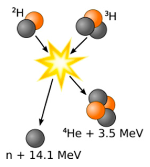
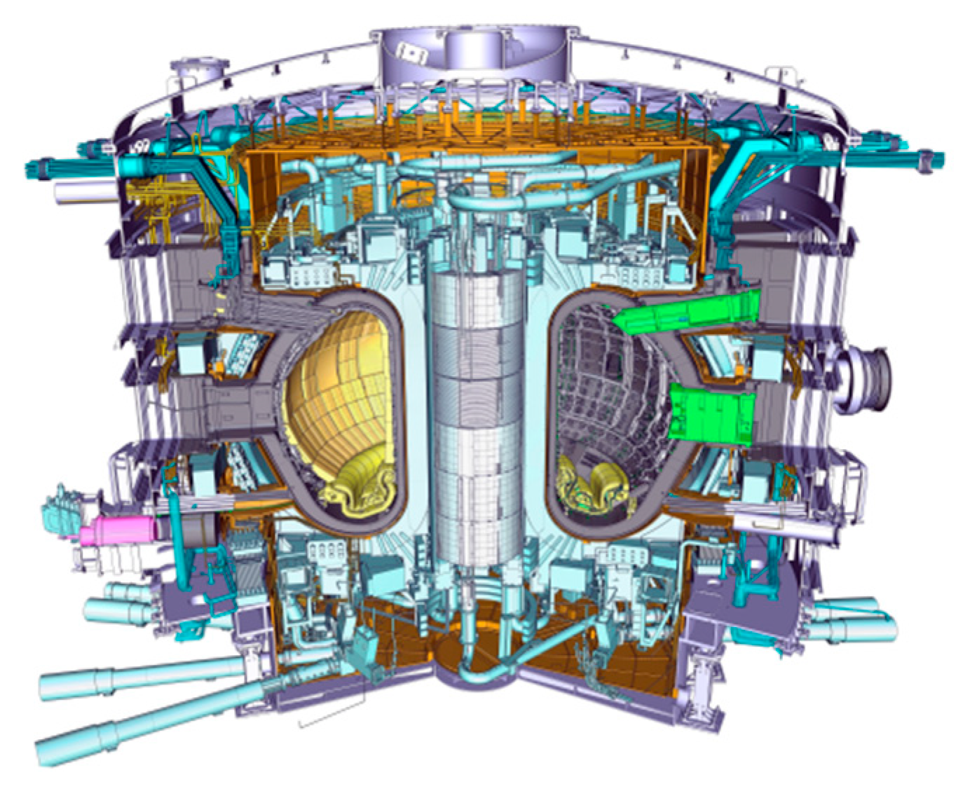
2. Nuclear System
- -
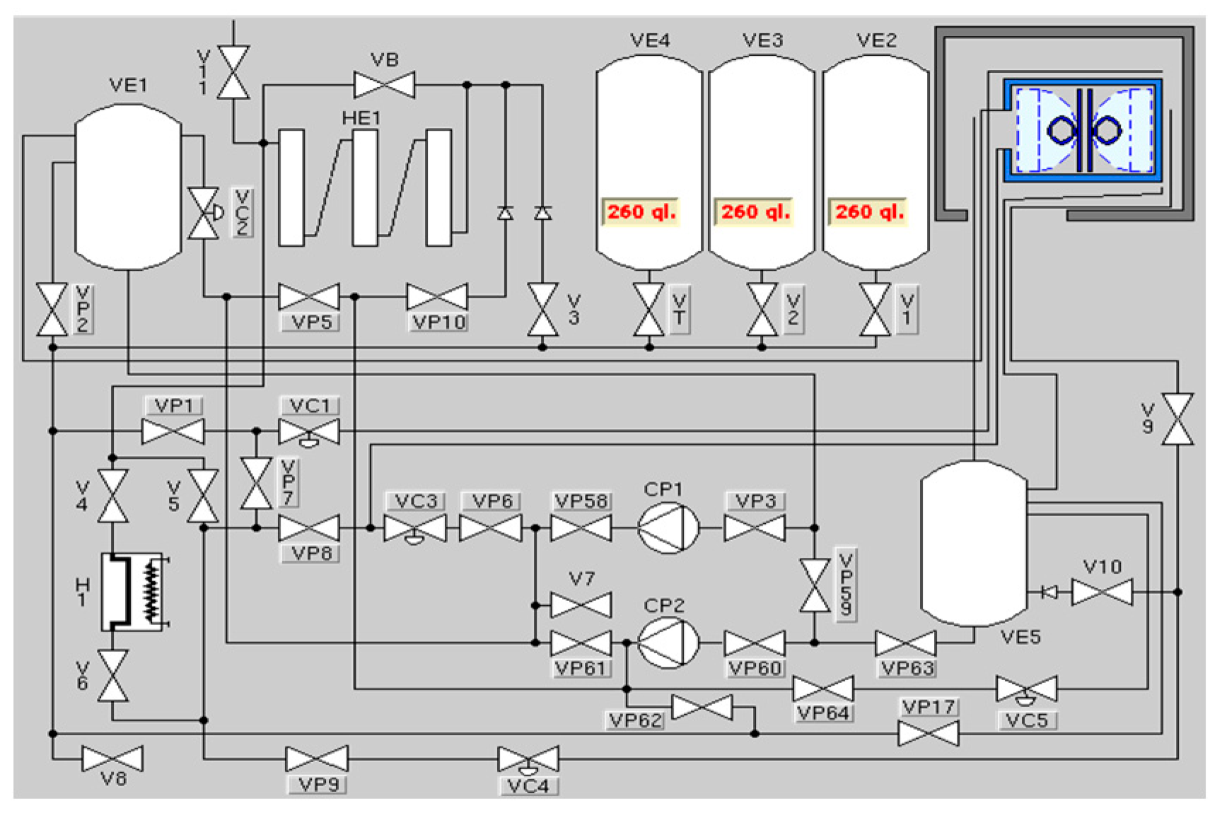
- Three buffer tanks of fluid nitrogen with an all-out limit of 90,000 L and pressure of 2.5 bar;
- -
- Two cryogenic pumps lubricated by a similar fluid nitrogen;
- -
- Two evaporators;
- -
- Tanks, valves, and common extras.
3. Literature Review: State of the Art of Safety Allocation Methods
- -
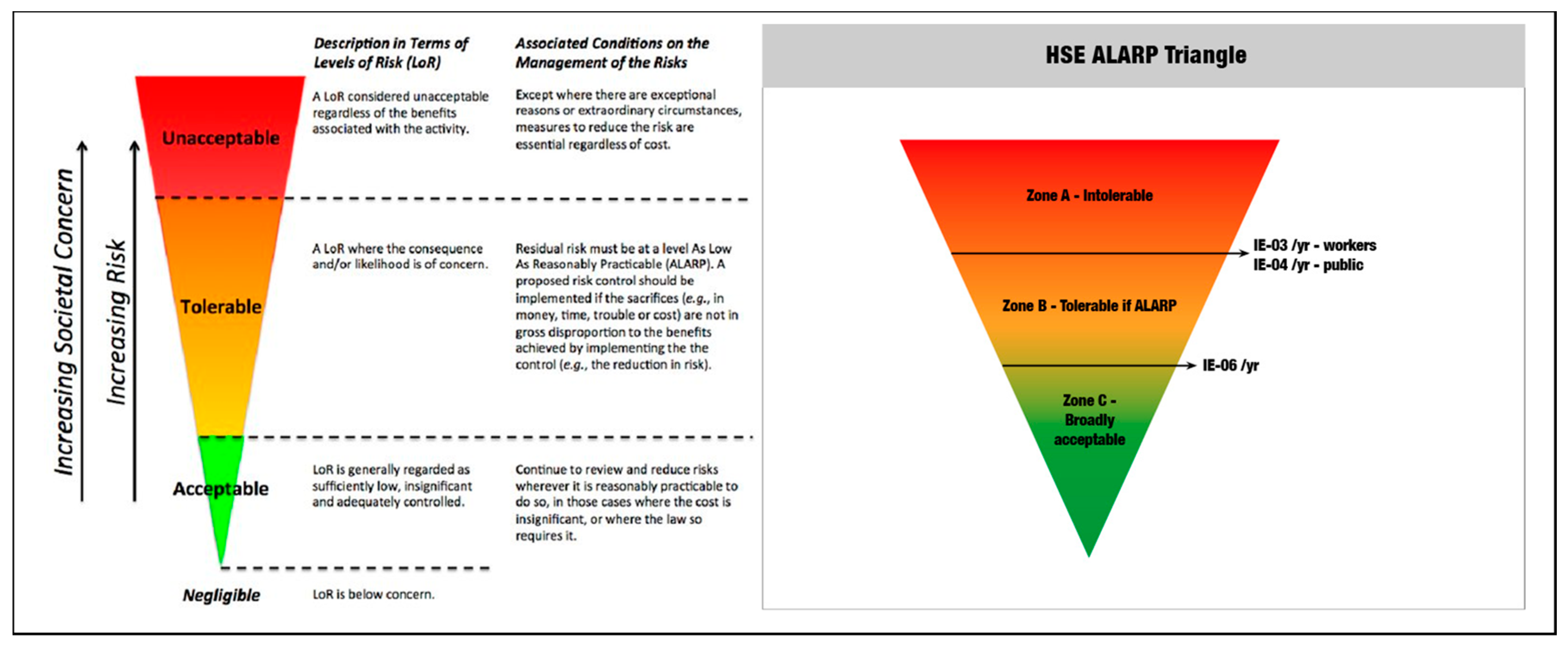
- The “As Low As Reasonably Practicable” method (ALARP);
- -
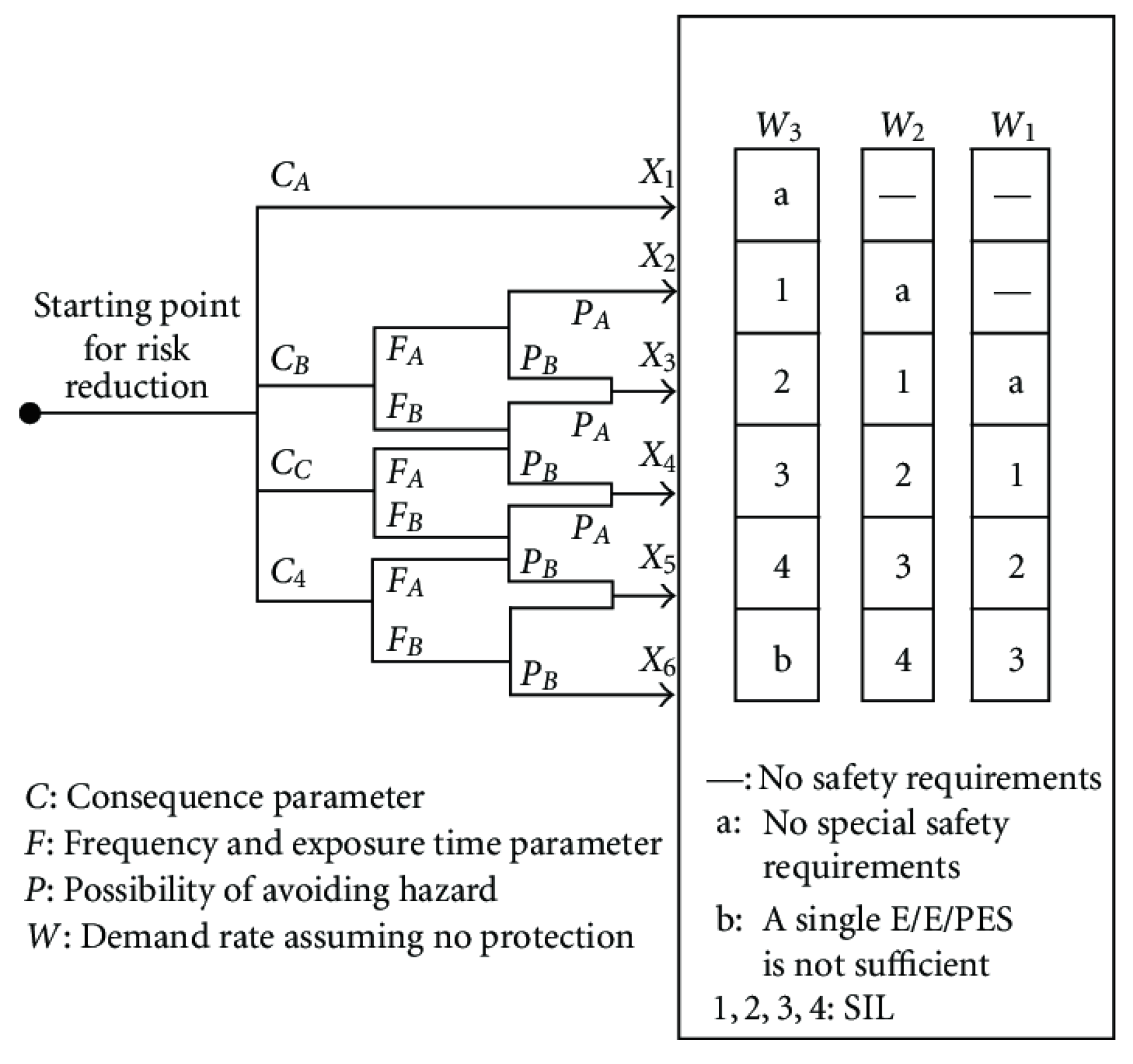
- The Risk Graph method;
- -
- Layers of Protection Analysis (LOPA);
- -
- Hazardous event severity matrix.
3.1. ALARP Method
- -
- It is easy to understand and apply.
- -
- However, there are numerous weaknesses and limitations:
- -
- It is qualitative methodology;
- -
- It is very difficult to define an objective wi for every unit.
3.2. The Risk Graph Method
- -
- It can be conducted both qualitatively and quantitatively;
- -
- It is easy to understand and apply.
- -
- However, there is a great limitation:
- -
- It is only suitable for series configuration.
3.3. LOPA Method
- -
- It can be conducted both qualitatively and quantitatively;
- -
- It is incorporated into HAZOP analysis.
- -
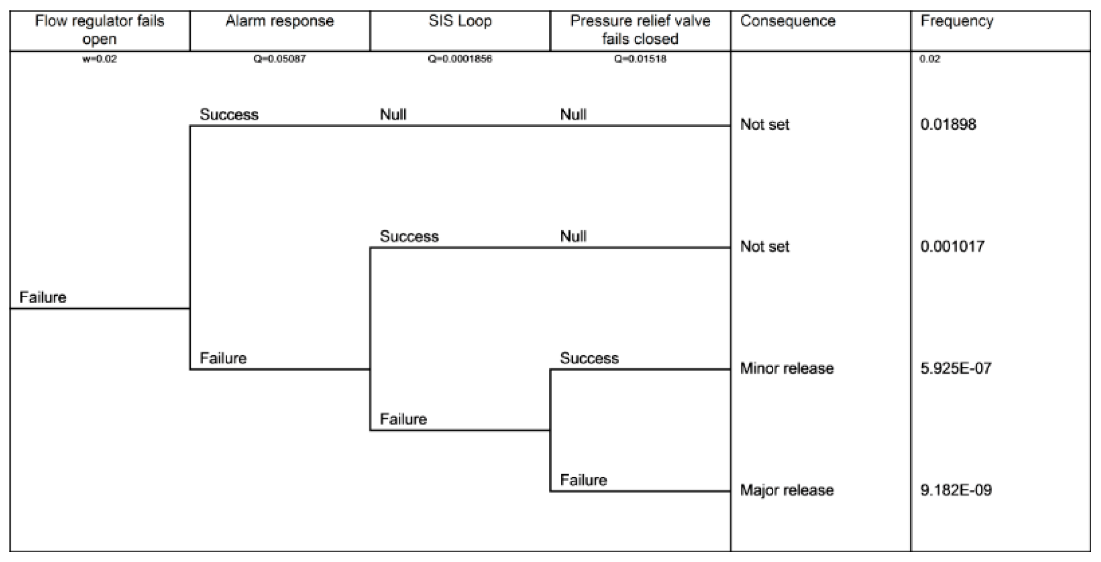
- It is only suitable for low-demand systems;
- -
- It is only suitable for series configuration.
3.4. Hazardous Event Severity Matrix
- -
- It can be conducted both qualitatively and quantitatively;
- -
- It is very simple.
- -
- It is only suitable for series configuration.
- -
- It is quantitative methodology;
- -
- It is suitable for complex systems where high safety standards are required.
- -
- The sum of the number of functions with technological risks has no scientific reason;
- -
- It is only suitable for series configuration.
- -
- Environmental and technological hazards should have the same importance;
- -
- It is necessary to value the real influence of each hazard on the considered unit.
- -
- Thermonuclear systems are in the production phase—many factors are known (system criticality, technology, mission time, etc.);
- -
- Thermonuclear systems have a complexity similar to that of aerospace;
- -
- Thermonuclear system detection is an important parameter for safety allocation.
4. Critical Risks Method
- ✓ Generality;
- ✓ Standardization of inputs;
- ✓ Economy;
- ✓ Realistic and achievable requirements.
- -
- f = 1 means a little influence of environmental conditions on unit i;
- -
- f = 100 means a great influence of environmental conditions on unit i.
- -
- g = 1 means a little influence of technological conditions on unit i;
- -
- g = 100 means a great influence of technological conditions on unit i.
5. Application of the CRM
- -
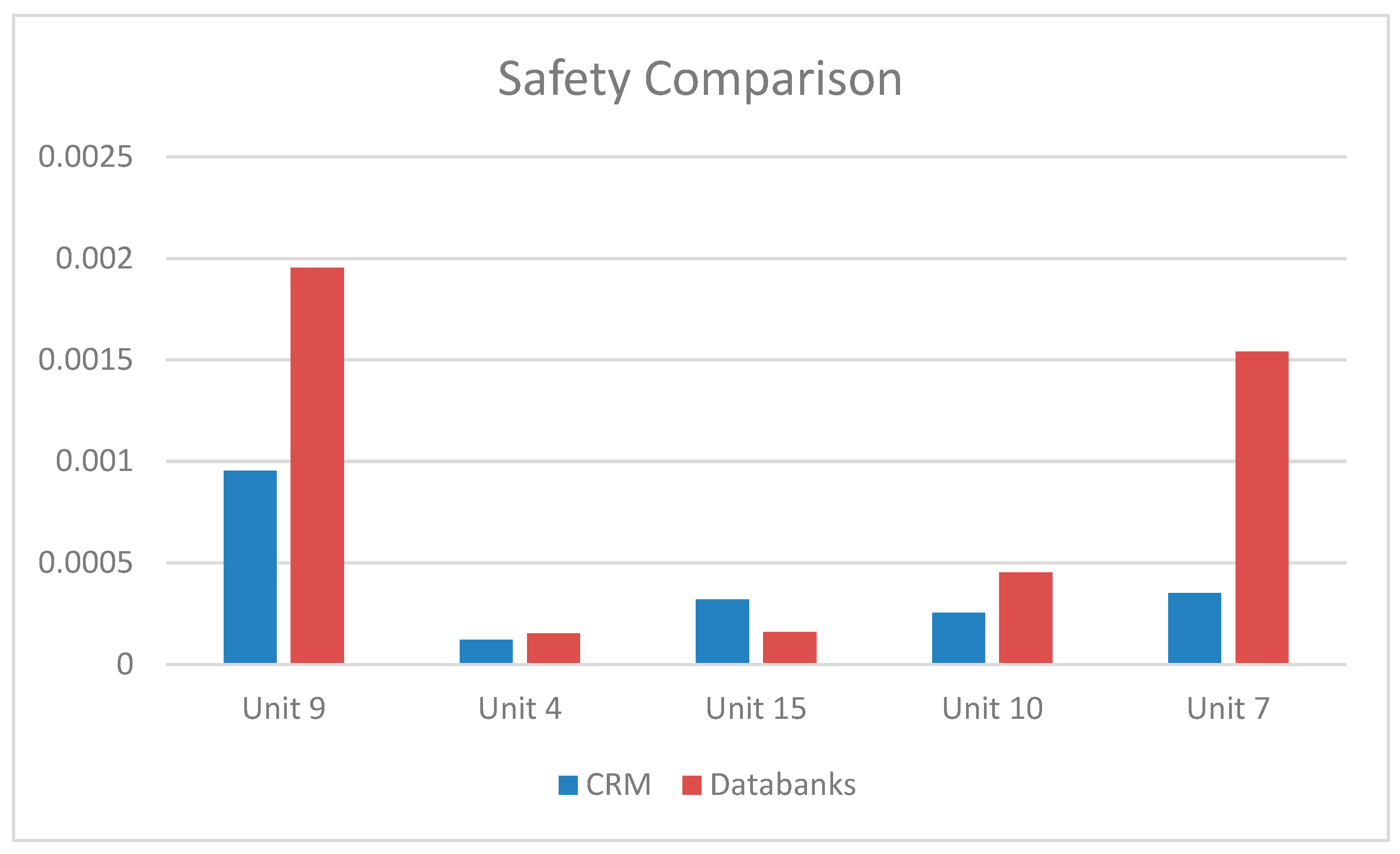
- Reduction of S(t)allocat for Units 4, 15 and 10 (parallel configuration); the average value is 28.61%. This means a good alignment with respect to the databank and a substantial savings in the choice of less-performing units;
- -
- Reduction of MAD of about 32.93%;
- -
- Reduction of ∑(-έtechnological) of about 38.69%.
- -
- The allocated safety values are comparable to the supplied safety ones;
- -
- The units’ performance and hierarchy are respected (Figure 8).
- -
- Factors A2 and A3 are quali-quantitative values;
- -
- Factor A5 is a qualitative value and is difficult to evaluate without an expert judgement.
6. Conclusions
- -
- The CRM solves the fundamental problem (parallel configurations) by using new indexes (A1, A2, A3, A4, A5, and A6);
- -
- The CRM results allow the efficient allocation of safety values, meeting customer needs, controlling reasonable support costs, and decreasing manufacturing and maintenance costs [31].
- -
- The comparison with literature is described as follows:
- -
- The MAD of the CRM is smaller than the MAD of the literature methods and is equal to 5.16 × 10⁻⁴ (failures/year).
- -
- The ∑(−έtechnological) of the CRM is smaller than the ∑(−έtechnological) of the literature methods and is equal to −2.42 × 10⁻³ (failures/year).
Author Contributions
Funding
Acknowledgments
Conflicts of Interest
References
- IEC 61508. Functional Safety of Electical/Electronic/Programmable Electronic Safety-Related Systems, Part 1–7; International Electrotechnical Commission: Geneva, Switzerland, 2010. [Google Scholar]
- IEC 61511. Functional Safety: Safety Instrumented Syystems for the Process Industry Sector, Part 1–3; International Electrotechnical Commission: Geneva, Switzerland, 2003. [Google Scholar]
- IEC 62061. Safety of Machinery—Functional Safety of Safety-related Electrical, Electronic and Programmable Electronic Control Systems; International Electrotechnical Commission: Geneva, Switzerland, 2005. [Google Scholar]
- Baybutt, P. An improved risk graph approach for determination of safety integrity levels (SILs). Proc. Saf. Prog. 2007, 26, 66–76. [Google Scholar] [CrossRef]
- Baybutt, P. The use of risk matrices and risk graphs for SIL determination. Proc. Saf. Prog. 2014, 33, 179–182. [Google Scholar] [CrossRef]
- Nait-Said, R.; Zidani, F.; Ouzraoui, N. Modified risk graph method using fuzzy rulebased approach. J. Hazard. Mater. 2009, 164, 651–658. [Google Scholar] [CrossRef] [PubMed]
- Salis, C. Using Risk Graphs for Safety Integrity Level (SIL) Assessment—A User-Guide for Chemical Engineers; IChemE: London, UK, 2011. [Google Scholar]
- CCPS. Guidelines for Safety Automation of Chemical Processes. Center for Chemical Process Safety; American Institute of Chemical Engineers: New York, NY, USA, 1993. [Google Scholar]
- Rausand, M. Risk assessment: Theory, Methods, and Applications; Wiley: Hoboken, NJ, USA, 2011. [Google Scholar]
- CCPS. Layer of Protection Analysis: Simplified Process Risk Assessment. Center for Chemical Process Safety; American Institute of Chemical Engineers: New York, NY, USA, 2001. [Google Scholar]
- NOG-070. Application of IEC 61508 and IEC 61511 in the Norwegian Petroleum Industy; The Norwegian Oil and Gas Association: Stavanger, Norway, 2004. [Google Scholar]
- Summers, A.E. Introduction to layers of protection analysis. J. Hazard. Mater. 2003, 104, 163–168. [Google Scholar] [CrossRef]
- Longo, J.M.A.; Luedeke, H.; Kordulla, W.; Molina, R. Extrapolating Aero Data from a Demonstrator to an Operational Vehicle. In Proceedings of the 4th International Symposium Atmospheric Reentry Vehicles & Systems, Archacon, France, 21–23 March 2005. [Google Scholar]
- Lindemuth, I.R.; Siemon, R.E. The fundamental parameter space of controlled thermonuclear fusion. Source Am. J. Phys. 2000, 77, 407–416. [Google Scholar] [CrossRef]
- Harms, A.A.; Schoepf, K.F.; Miley, G.H.; Kingdon, D.R. Principles of Fusion Energy; World Scientific Publishing Co.: Singapore, 2002; ISBN 981-02-4335-9. [Google Scholar]
- Di Bona, G.; Forcina, A.; Falcone, D.; Silvestri, A. IFM target 2.0: An innovative method to define reliability target for prototype systems. Int. J. Adv. Manuf. Technol. 2018, 95. [Google Scholar] [CrossRef]
- Di Bona, G.; Duraccio, V.; Silvestri, A.; Forcina, A. Validation and Application of a Safety Allocation Technique (Integrated Hazard Method) to an Aerospace prototype. In Proceedings of the MIC2014, Innsbruck, Austria, 17–19 February 2014. [Google Scholar]
- Silvestri, A.; Forcina, A.; Di Bona, G.; Petrillo, A.; De Felice, F. A-IFM reliability allocation model based on multicriteria approach. Int. J. Qual. Reliab. Manag. 2016, 33, 676–698. [Google Scholar]
- Kosovac, A.; Davidson, B.; Malano, H. Are We Objective? A Study into the Effectiveness of Risk Measurement in the Water Industry. Sustainability 2019, 11, 1279. [Google Scholar] [CrossRef] [Green Version]
- IEC. IEC 60812:2006(E) Analysis Techniques for System Reliability—Procedure for Failure Mode and Effect Analysis (FMEA), 2nd ed.; IEC: Brussels, Belgium, 2006. [Google Scholar]
- ISO, ISO 31000:2009(E). Risk Management—Principles and Guidelines, 1st ed.; ISO: Geneva, Switzerland, 2009. [Google Scholar]
- Di Bona, G.; Forcina, A.; Silvestri, A.; Petrillo, A. Total Efficient Risk Priority Number (TERPN): A new method for risk assessment. J. Risk Res. 2018, 21, 1384–1408. [Google Scholar] [CrossRef]
- Falcone, D.; De Felice, F.; Di Bona, G.; Duraccio, V.; Silvestri, A. Risk assessment in a co-generation system: Validation of a new safety allocation technique. In Proceedings of the Applied Simulation and Modelling, Palma de Mallorca, Spain, 29–31 August 2007. [Google Scholar]
- De Felice, F.; Petrillo, A.; Gnoni, M.G. Risks analysis for assessing safety in railway tunnel Safety, Reliability and Risk Analysis: Beyond the Horizon. In Proceedings of the European Safety and Reliability Conference, ESREL 2013, Amsterdam, The Netherlands, 29 September–3 October 2013; pp. 2281–2287. [Google Scholar]
- Caputo, A.C.; Pelagagge, P.M.; Salini, P. Effects of preventive maintenance parameters on manufacturing equipment operational performances. In Proceedings of the 16th ISSAT International Conference on Reliability and Quality in Design, Washington, DC, USA, 5–7 August 2010; pp. 1–5. [Google Scholar]
- Jin, H.; Lundteigen, M.A.; Rausand, M. Uncertainty assessment of reliability estimates for safety-instrumented systems. Proc. Inst. Mech. Eng. Part O J. Risk Reliab. 2012, 226, 646–655. [Google Scholar] [CrossRef] [Green Version]
- MIL-STD-882D. Standard Practice for System Safety; U.S. Department of Defence: Washington, DC, USA, 2000.
- Vaurio, J.K. Uncertainties and quantification of common cause failure rates and probabilities for system analyses. Reliab. Eng. Syst. Saf. 2005, 90, 186–195. [Google Scholar] [CrossRef]
- Di Bona, G.; Silvestri, A.; Forcina, A. Critical flow method: A new reliability allocation approach for a thermonuclear system. Qual. Reliab. Eng. Int. 2016, 32, 1677–1691. [Google Scholar] [CrossRef]
- Marhavilas, P.K.; Filippidis, M.; Koulinas, G.K.; Koulouriotis, D.E. A HAZOP with MCRM based risk-assessment approach: Focusing on the deviations with economic/health/environmental impacts in a process industry. Sustainability 2020, 12, 993. [Google Scholar] [CrossRef] [Green Version]
- Zhu, R.; Li, X.; Hu, X.; Hu, D. risk analysis of chemical plant explosion accidents based on Bayesian network. Sustainability 2020, 12, 37. [Google Scholar] [CrossRef] [Green Version]

| Factor | Min | Max |
|---|---|---|
| Technology | 1 | 10 |
| Dimension | 1 | 10 |
| Material | 1 | 10 |
| Time | 1 | 10 |
| Unit 1. Manual valves. | Unit 11. Cryostat. |
| Unit 2. Safety valves. | Unit 12. Liquid nitrogen tanks. |
| Unit 3. Restraint valves. | Unit 13. Separation tank. |
| Unit 4. On-off valves. | Unit 14. Collection tank. |
| Unit 5. Solenoid valves. | Unit 15. Main evaporators. |
| Unit 6. Breaking discs. | Unit 16. Secondary evaporators. |
| Unit 7. Pressure valves. | Unit 17. Heater. |
| Unit 8. Self-regulation valves. | Unit 18. Cryogenic pumps. |
| Unit 9. Pressure-regulation valves. | Unit 19. Compressed air system. |
| Unit 10. Level valves. | Unit 20. Measure modules. |
| TOP EVENT | Minor | Marginal | Critical | Catastrophic |
|---|---|---|---|---|
| Frequent | ||||
| Probable | Cooling Cycle Interruption | |||
| Occasional | Low Pressure in Cryostat | |||
| Rare | Damage in Cryostat | |||
| Improbable |
| TOP Event | Accepted Faults/Mission | Safety Target (Faults/Year) |
|---|---|---|
| T.E.1: Catastrophic | 1/1000 | 0.002 |
| T.E.2: Critical | 1/500 | 0.004 |
| T.E.3: Minor | 1/250 | 0.008 |
| Unit | T.E. 1 | T.E. 2 | T.E. 3 | |||||
|---|---|---|---|---|---|---|---|---|
| S | O | D | RPN | W% | 0.002 | 0.004 | 0.008 | |
| 1. Manual valves | 5 | 5 | 6 | 150 | 2.44% | 4.89 × 10⁻⁵ | 1.96 × 10⁻⁷ | 1.56 × 10⁻⁹ |
| 2. Safety valves | 10 | 5 | 6 | 300 | 4.89% | 9.78 × 10⁻⁵ | 3.91 × 10⁻⁷ | 3.13 × 10⁻⁹ |
| 3. Restraint valves | 6 | 5 | 5 | 150 | 2.44% | 4.89 × 10⁻⁵ | 1.96 × 10⁻⁷ | 1.56 × 10⁻⁹ |
| 4. On–off valves | 8 | 9 | 9 | 648 | 10.56% | 2.11 × 10⁻⁴ | 8.45 × 10⁻⁷ | 6.76 × 10⁻⁹ |
| 5. Solenoid valves | 9 | 9 | 5 | 405 | 6.60% | 1.32 × 10⁻⁴ | 5.28 × 10⁻⁷ | 4.22 × 10⁻⁹ |
| 6. Breaking discs | 2 | 3 | 5 | 30 | 0.49% | 9.78 × 10⁻⁶ | 3.91 × 10⁻⁸ | 3.13 × 10⁻¹⁰ |
| 7. Valves at static | 5 | 5 | 8 | 200 | 3.26% | 6.5 × 10⁻⁵ | 2.61 × 10⁻⁷ | 2.09 × 10⁻⁹ |
| 8. Self-regulation valves | 6 | 6 | 7 | 252 | 4.11% | 8.22 × 10⁻⁵ | 3.29 × 10⁻⁷ | 2.63 × 10⁻⁹ |
| 9. Pressure-regulation valves | 8 | 9 | 6 | 432 | 7.04% | 1.41 × 10⁻⁴ | 5.63 × 10⁻⁷ | 4.51 × 10⁻⁹ |
| 10. Level valves | 4 | 6 | 8 | 192 | 3.13% | 6.26 × 10⁻⁵ | 2.50 × 10⁻⁷ | 2.00 × 10⁻⁹ |
| 11. Cryostat | 5 | 1 | 9 | 45 | 0.73% | 1.47 × 10⁻⁵ | 5.87 × 10⁻⁸ | 4.69 × 10⁻¹⁰ |
| 12. Liquid nitrogen tanks | 6 | 5 | 6 | 180 | 2.93% | 5.87 × 10⁻⁵ | 2.35 × 10⁻⁷ | 1.88 × 10⁻⁹ |
| 13. Separation tank | 8 | 9 | 8 | 576 | 9.39% | 1.88 × 10⁻⁴ | 7.51 × 10⁻⁷ | 6.01 × 10⁻⁹ |
| 14. Collection tank | 9 | 7 | 7 | 441 | 7.19% | 1.44 × 10⁻⁴ | 5.75 × 10⁻⁷ | 4.60 × 10⁻⁹ |
| 15. Main evaporators | 4 | 5 | 8 | 160 | 2.61% | 5.22 × 10⁻⁵ | 2.09 × 10⁻⁷ | 1.67 × 10⁻⁹ |
| 16. Secondary evaporators | 5 | 4 | 6 | 120 | 1.96% | 3.91 × 10⁻⁵ | 1.56 × 10⁻⁷ | 1.25 × 10⁻⁹ |
| 17. Heater | 6 | 8 | 9 | 432 | 7.04% | 1.41 × 10⁻⁴ | 5.63 × 10⁻⁷ | 4.51 × 10⁻⁹ |
| 18. Cryogenic pumps | 9 | 6 | 9 | 486 | 7.92% | 1.58 × 10⁻⁴ | 6.34 × 10⁻⁷ | 5.07 × 10⁻⁹ |
| 19. Compressed air system | 9 | 4 | 8 | 288 | 4.69% | 9.39 × 10⁻⁵ | 3.76 × 10⁻⁷ | 3.00 × 10⁻⁹ |
| 20. Measure modules | 9 | 9 | 8 | 648 | 10.56% | 2.11 × 10⁻⁴ | 8.45 × 10⁻⁷ | 6.76 × 10⁻⁹ |
| Unit | T.E. 1 | T.E. 2 | T.E. 3 | ||||||
|---|---|---|---|---|---|---|---|---|---|
| De | Dt | F | C | AF | W% | 0.002 | 0.004 | 0.008 | |
| 1. Manual valves | 2 | 1 | 0.02 | 95 | 98.9 | 0.54% | 1.09 × 10⁻⁵ | 4.34 × 10⁻⁸ | 3.48 × 10⁻¹⁰ |
| 2. Safety valves | 3 | 2 | 0.1 | 126 | 267.6 | 1.47% | 2.94 × 10⁻⁵ | 1.18 × 10⁻⁷ | 9.40 × 10⁻¹⁰ |
| 3. Restraint valves | 5 | 3 | 0.04 | 142 | 436.68 | 2.40% | 4.80 × 10⁻⁵ | 1.92 × 10⁻⁷ | 1.53 × 10⁻⁹ |
| 4. On–off valves | 5 | 1 | 0.02 | 235 | 244.7 | 1.34% | 2.69 × 10⁻⁵ | 1.07 × 10⁻⁷ | 8.60 × 10⁻¹⁰ |
| 5. Solenoid valves | 3 | 4 | 0.05 | 530 | 2149.5 | 11.80% | 2.36 × 10⁻⁴ | 9.44 × 10⁻⁷ | 7.55 × 10⁻⁹ |
| 6. Breaking discs | 1 | 3 | 0.05 | 159 | 485.95 | 2.67% | 5.34 × 10⁻⁵ | 2.13 × 10⁻⁷ | 1.71 × 10⁻⁹ |
| 7. Valves at static | 2 | 1 | 0.05 | 235 | 248.75 | 1.37% | 2.73 × 10⁻⁵ | 1.09 × 10⁻⁷ | 8.74 × 10⁻¹⁰ |
| 8. Self-regulation valves | 3 | 3 | 0.05 | 256 | 783.8 | 4.30% | 8.61 × 10⁻⁵ | 3.44 × 10⁻⁷ | 2.75 × 10⁻⁹ |
| 9. Pressure-regulation valves | 4 | 2 | 0.05 | 568 | 1168.4 | 6.41% | 1.28 × 10⁻⁴ | 5.13 × 10⁻⁷ | 4.11 × 10⁻⁹ |
| 10. Level valves | 4 | 2 | 0.05 | 452 | 930.6 | 5.11% | 1.02 × 10⁻⁴ | 4.09 × 10⁻⁷ | 3.27 × 10⁻⁹ |
| 11. Cryostat | 4 | 2 | 0.06 | 148 | 308.88 | 1.70% | 3.39 × 10⁻⁵ | 1.36 × 10⁻⁷ | 1.09 × 10⁻⁹ |
| 12. Liquid nitrogen tanks | 3 | 4 | 0.04 | 239 | 968.56 | 5.32% | 1.06 × 10⁻⁴ | 4.25 × 10⁻⁷ | 3.40 × 10⁻⁹ |
| 13. Separation tank | 2 | 3 | 0.1 | 215 | 668.5 | 3.67% | 7.34 × 10⁻⁵ | 2.94 × 10⁻⁷ | 2.35 × 10⁻⁹ |
| 14. Collection tank | 3 | 4 | 0.07 | 786 | 3202.02 | 17.58% | 3.52 × 10⁻⁴ | 1.41 × 10⁻⁶ | 1.13 × 10⁻⁸ |
| 15. Main evaporators | 4 | 2 | 0.03 | 125 | 257.75 | 1.42% | 2.83 × 10⁻⁵ | 1.13 × 10⁻⁷ | 9.06 × 10⁻¹⁰ |
| 16. Secondary evaporators | 2 | 3 | 0.05 | 369 | 1127.45 | 6.19% | 1.24 × 10⁻⁴ | 4.95 × 10⁻⁷ | 3.96 × 10⁻⁹ |
| 17. Heater | 5 | 1 | 0.04 | 357 | 376.28 | 2.07% | 4.13 × 10⁻⁵ | 1.65 × 10⁻⁷ | 1.32 × 10⁻⁹ |
| 18. Cryogenic pumps | 3 | 2 | 0.04 | 159 | 327.36 | 1.80% | 3.59 × 10⁻⁵ | 1.44 × 10⁻⁷ | 1.15 × 10⁻⁹ |
| 19. Compressed air system | 2 | 3 | 0.08 | 754 | 2324.32 | 12.76% | 2.55 × 10⁻⁴ | 1.02 × 10⁻⁶ | 8.17 × 10⁻⁹ |
| 20. Measure modules | 1 | 4 | 0.01 | 458 | 1837.58 | 10.09% | 2.02 × 10⁻⁴ | 8.07 × 10⁻⁷ | 6.46 × 10⁻⁹ |
| Method | Fitting to Nuclear System | Not Fitting to Nuclear System |
|---|---|---|
| RPN | Index factors oriented safety allocation. | Functional factors oriented safety allocation. The buffer effect is not evaluated. |
| Sphynx | Index factors oriented safety allocation. Units and Top Events are linked. The allocation factors are based on operating and environmental conditions of units. | No information on operating cycles. The buffer effect is not evaluated. Functional importance is the same for all units. |
| Unit 9—Pressure-Regulation Valves | |||
|---|---|---|---|
| Functions | Mode | Note | Linked Units |
| Control valve opening VC4 according to the pressure of cryostat during the PLC cycle. | The opening is partial. Nominal pressure of c.a. 20 mm. | Incorrect functioning of the valve and its equipment (pressure sensors) could increase pressure in the cryostat. | Unit 11 |
| Control valve opening VC1 according to the cooling gradient magnets. | The opening is partial. | If the valve is opened excessively, a considerable amount of nitrogen is discharged into the cryostat and into the reservoir. | Unit 11 |
| Setting pressure of the CP1 pump by VC2. | The opening is partial. | Nothing | Nothing |
| Setting pressure in the copper cooling circuit using VC3. | The opening is partial. Nominal pressure of 1.5 bar. | After the shot, the fluid heats up by increasing the volume. The valve prevents excessive pressure increase due to fluid mass input. | Unit 2 |
| Unit 9—Pressure-Regulation Valves | |||||
|---|---|---|---|---|---|
| Functions | Failure Mode | Causes | Effects | Corrective Actions | Note |
| Control valve opening VC4 according to the pressure of cryostat during the PLC cycle. | Failure—Power Loss | Wear; Electrical supply interruption of the compressors and failure of start-up of auxiliary generators. | The nitrogen level increases | 1.1: Maintenance; 1.2: Restore compressed air supply | Nothing |
| Control valve opening VC1 according to the cooling gradient magnets. | Failure | Wear | The nitrogen level increases | 2.1: Maintenance | Dispersion of nitrogen |
| Setting pressure of the CP1 pump using VC2. | Failure—Power Loss | Wear; Electrical supply interruption of the compressors and failure of start-up of auxiliary generators. | The nitrogen level increases | 3.1: Maintenance | Nothing |
| Setting pressure in the copper cooling circuit using VC3. | Failure | Wear | The nitrogen level increases | 4.1: Maintenance | Damage of the cryostat |
| Elements | A1 | A2 | A3 | A4 | A5 |
|---|---|---|---|---|---|
| Unit 9 | 1 | 0.98 | 0.90 | 50.00 | 235.00 |
| Unit 4 | 0.33 | 0.95 | 0.90 | 20.00 | 235.00 |
| Unit 15 | 0.33 | 0.98 | 0.95 | 20.00 | 568.00 |
| Unit 10 | 0.33 | 0.98 | 0.95 | 20.00 | 452.00 |
| Unit 7 | 1 | 0.98 | 0.95 | 33.00 | 125.00 |
| Elements | AF | wi | S(t) |
|---|---|---|---|
| Unit 9 | 10,363.50 | 47.66% | 9.53 × 10-04 |
| Unit 4 | 1326.11 | 6.10% | 1.22 × 10-04 |
| Unit 15 | 3472.33 | 15.97% | 3.19 × 10-04 |
| Unit 10 | 2763.19 | 12.71% | 2.54 × 10-04 |
| Unit 7 | 3820.78 | 17.57% | 3.51 × 10-04 |
| CRM | Databanks | έ | έtech (%) | RPN | Databanks | έ (%) | έtech (%) | Sphynx | Databanks | έ (%) | έtech (%) | |
|---|---|---|---|---|---|---|---|---|---|---|---|---|
| Unit 9 | 9.53 × 10⁻⁴ | 1.95 × 10⁻³ | 1.00 × 10⁻³ | −1.00 × 10⁻³ | 1.41 × 10⁻⁴ | 1.95 × 10⁻³ | 1.81 × 10⁻³ | −1.81 × 10⁻³ | 1.28 × 10⁻⁴ | 1.95 × 10⁻³ | 1.82 × 10⁻³ | −1.82 × 10⁻³ |
| Unit 4 | 1.22 × 10⁻⁴ | 1.52 × 10⁻⁴ | 3.00 × 10⁻⁵ | −3.00 × 10⁻⁵ | 2.11 × 10⁻⁴ | 1.52 × 10⁻⁴ | 5.93 × 10⁻⁵ | 5.93 × 10⁻⁵ | 2.69 × 10⁻⁵ | 1.52 × 10⁻⁴ | 1.25 × 10⁻⁴ | −1.25 × 10⁻⁴ |
| Unit 15 | 3.19 × 10⁻⁴ | 1.59 × 10⁻⁴ | 1.60 × 10⁻⁴ | 1.60 × 10⁻⁴ | 5.22 × 10⁻⁵ | 1.59 × 10⁻⁴ | 1.07 × 10⁻⁴ | −1.07 × 10⁻⁴ | 2.83 × 10⁻⁵ | 1.59 × 10⁻⁴ | 1.31 × 10⁻⁴ | −1.31 × 10⁻⁴ |
| Unit 10 | 2.54 × 10⁻⁴ | 4.54 × 10⁻⁴ | 2.00 × 10⁻⁴ | −2.00 × 10⁻⁴ | 6.26 × 10⁻⁵ | 4.54 × 10⁻⁴ | 3.92 × 10⁻⁴ | −3.92 × 10⁻⁴ | 1.02 × 10⁻⁴ | 4.54 × 10⁻⁴ | 3.52 × 10⁻⁴ | −3.52 × 10⁻⁴ |
| Unit 7 | 3.51 × 10⁻⁴ | 1.54 × 10⁻³ | 1.19 × 10⁻³ | −1.19 × 10⁻³ | 6.52 × 10⁻⁵ | 1.54 × 10⁻³ | 1.48 × 10⁻³ | −1.48 × 10⁻³ | 2.73 × 10⁻⁵ | 1.54 × 10⁻³ | 1.51 × 10⁻³ | −1.51 × 10⁻³ |
| MADIFM | 5.16 × 10⁻⁴ | Tot—έt•10chIFM = −2.42 × 10⁻³ | MADFOO | 7.69 × 10⁻⁴ | Totέt•10chFOO = −3.79 × 10⁻³ | MADKarmiol | 7.84 × 10⁻⁴ | Totέt•10chKarmiol = −3.95 × 10⁻³ |
© 2020 by the authors. Licensee MDPI, Basel, Switzerland. This article is an open access article distributed under the terms and conditions of the Creative Commons Attribution (CC BY) license (http://creativecommons.org/licenses/by/4.0/).
Share and Cite
Di Bona, G.; Forcina, A.; Falcone, D.; Silvestri, L. Critical Risks Method (CRM): A New Safety Allocation Approach for a Critical Infrastructure. Sustainability 2020, 12, 4949. https://doi.org/10.3390/su12124949
Di Bona G, Forcina A, Falcone D, Silvestri L. Critical Risks Method (CRM): A New Safety Allocation Approach for a Critical Infrastructure. Sustainability. 2020; 12(12):4949. https://doi.org/10.3390/su12124949
Chicago/Turabian StyleDi Bona, Gianpaolo, Antonio Forcina, Domenico Falcone, and Luca Silvestri. 2020. "Critical Risks Method (CRM): A New Safety Allocation Approach for a Critical Infrastructure" Sustainability 12, no. 12: 4949. https://doi.org/10.3390/su12124949
APA StyleDi Bona, G., Forcina, A., Falcone, D., & Silvestri, L. (2020). Critical Risks Method (CRM): A New Safety Allocation Approach for a Critical Infrastructure. Sustainability, 12(12), 4949. https://doi.org/10.3390/su12124949


