Article

Virtual Reality-Based Ergonomic Modeling and Evaluation Framework for Nuclear Power Plant Operation and Control

School of Industrial Engineering, Kumoh National Institute of Technology, Gumi 39177, Korea
*
Author to whom correspondence should be addressed.
Sustainability 2019, 11(9), 2630; https://doi.org/10.3390/su11092630
Submission received: 5 April 2019 / Revised: 1 May 2019 / Accepted: 2 May 2019 / Published: 7 May 2019
(This article belongs to the Section Sustainable Engineering and Science)

Abstract

:
The purpose of this study is to introduce a new and efficient virtual model-based ergonomic simulation framework utilizing recent anthropometric data for a digitalized main control room in an advanced nuclear power plant. The system interface of the main control room has been undergoing digitalization via various information and control consoles. Console operators often face human–computer interactive problems due to inappropriate console design. Computational models with a process of visual perception and variables of anthropometric data are developed for designing and evaluating operator consoles with the requirements of human factor guidelines. From the 3D computational model and simulation application, console dimensions and a designing test module, which would be used for designing suitable consoles with safety concerns in a nuclear plant, are proposed. To efficiently carry out console design and evaluation feedback, an intelligent design review system comprising a virtual modeling and simulation framework is developed. The proposed automated and virtual design review system provides console design efficiency and evaluation effectiveness. This study may influence methods of employing suitable design concepts with various anthropometric data in many areas with safety concerns and may show a feasible solution to designing and evaluating the main control room.

1. Introduction

While nuclear energy is considered by many analysts and policymakers as being representative of sustainable energies, safety issues and accidents in nuclear power plants (NPPs) are among the challenges in the construction of a nuclear plant and facilities. A number of institutions, including International Atomic Energy Agency (IAEA), have published relevant data and analyses [1] for preventing accidents and operation mistakes. Wheatley et al. [2] analyzed the 15 largest nuclear plant disasters and measured their severities. These accidents and incidents have led to the regulations and safety rules of NPPs becoming very tight. To illustrate, the United States Nuclear Regulatory Commission (NRC) has classified detailed guides [3] into 10 divisions, including power reactors, fuel and material facilities, transportation, and occupational health.
While a number of regulations and instructions guide every aspect in the modeling of an NPP from construction to operations, safe and efficient operation control of NPPs is considered one of the most important responsibilities. Several research studies, including that of Cipollaro and Lomonaco [4], have focused on integrating methodologies by combining nuclear safeguards, safety, and nuclear securities. These research studies indicated that the considerations of all safety-based components are required from the initial modeling stage of an NPP. In addition, these factors are considered in the evaluation of an operating NPP. This research considers this viewpoint and proposes an ergonomic modeling and evaluation framework for supporting nuclear safeguards, safety, and security.
According to the NRC [5], most NPP facilities and parts have to be monitored and controlled in a key space, i.e., the ‘control room’. It is defined as an area in an NPP from which most of the plant’s power production and emergency safety equipment can be operated using remote control methods. As the definition indicates, the control room plays a key role not only in operating the NPP, but also in taking measures in case of emergency situations. While there are many developments and advancements in the design and operations of the control room, this research focuses on how the control room in an NPP can be analyzed with various anthropometric data and ergonomic methods. Because NPP control operators work in the control room, human factor regulations [6] are applied to the control room more than any other facility in an NPP. According to the NRC [7], advanced NPP control rooms have to be controlled digitally with a highly integrated glass cockpit-style control room model where the digital control technology includes touch-screen controls, semiautonomous controls, and other advanced operator interfaces and technologies. While a number of control systems are operated in an NPP control room, regulatory instructions that demand careful design of interfaces between control devices and operators to prevent control mistakes or unintended delivery of NPP information have received enormous focus. In particular, operators’ anthropometric data-based ergonomic analyses have been conducted in order to achieve safe and efficient controls in an NPP. However, existing analyses are based on operational studies in a real control room, and these experiments then fail to conclude analyses and results covering various ranges of anthropometric data. Moreover, experiments in a real NPP environment might cause several measurement errors. In order to overcome this issue, Cha and Choi [8] developed a two-dimensional (2D) review system considering several types of anthropometric data. However, the research is limited in the fact that only several fixed places are analyzed and that the analyses are 2D-based.
In order to overcome these issues, this paper proposes a virtual reality (VR) model-based ergonomic analysis framework for a control room in an NPP. The constructed VR-based control room model is used for a modeling and simulation test bed with various types of anthropometric data. The desirable specifications for a better control room can then be derived quantitatively. The proposed framework is considered to be a sustainable and quantitative modeling and ergonomic analyzing framework for a control room in an NPP.
The following section introduces the relevant background and the literature reviews. Then, the existing guidelines and current issues for a control room in an NPP are explained in Section 3. The developed virtual model-based ergonomic analyzing framework is provided in Section 4, and Section 5 explains the design recommendations using the proposed framework.

2. Background and Literature Reviews

2.1. Main Control Room in a Nuclear Power Plant

While there are several control rooms in a general NPP, the most important control room is the main control room (MCR), as shown in Figure 1. Figure 1 shows a digital image of an MCR in Shin Kori NPP (SKN) 3 and 4, which are currently being operated in South Korea.
This paper considers the modeling and ergonomic analyses of several MCRs. Most of the design guides for MCRs follow the NRC-specified [7] design practices for communications and workstations in highly integrated control rooms.
As explained in the previous section, most or all of the MCR interface has been digitalized in advanced NPPs. In such systems, safety and reliability of the digital devices including a console are emphasized more than in any other systems. The interface of a NPP’s main digital control room consists of various operators’ workstation consoles, including a large display panel (LDP) and a safety console. Several regulatory guides [6,7] suggest that the workstation design in an MCR is a key working factor for operators. Thus, it is important to identify correlations between operators’ physical characteristics and devices’ mechanical characteristics in the broad context of human–machine interaction.
Several research studies [9,10] have shown that cognitive loads are gradually increased due to the greater amounts of information in a hybrid NPP with digital environments than in fully analog environments, although physical workloads are decreased. Because the possibility of causing human errors is high due to the massive amount of operational information, even in the case of highly skilled operators, it is critical to convey the relevant information clearly on indicators and control devices of the main control room of an existing NPP where the control of operations, such as operation, suspension, emergency, and abnormal operations, is carried out. The control room surveillance uses large display panels (LDPs) and workstations are conducted through operator consoles, and it is thus critical to design the console shape and layout through which information within the visual perception range can be identified and manipulated easily with actual devices.
However, in reality, the design of ergonomic interfaces considering numerous console shapes and layouts is not efficiently carried out due to the lack of a comprehensive system analysis and evaluation process [11].
This study aims to analyze the sensitivity of many independent variables according to recent anthropometric data for console design in order to optimize the operating environment from the cognitive ergonomic perspective. Ergonomic test results have often lacked in persuasiveness for safety accreditation because of the differences between design guidelines and review guidelines. Therefore, modeling and simulation-based quantitative evaluation may be better way to resolve the ergonomic issues on console design rather than guideline-based evaluation. Ultimately, this study aims to introduce an intelligent console design review system based on the modeling and simulation of an MCR currently under development. In particular, the proposed system’s effective viewing analyses help the layout of operators’ directing and controlling facilities within the range of operators’ information-processing capabilities.

2.2. Virtual Model-Based Applications in a Nuclear Power Plant

As mentioned in the previous section, this research proposed a new and efficient ergonomic analyzing framework for supporting the modeling and simulation of an MCR using a variety of anthropometric data. While there are various modeling and simulation tools and systems, this research uses a 3D virtual model-based system framework. As the main input to the developed framework is the anthropometric data of MCR operators, the information includes spatial data and its analyses require the relevant spatial analyses. For this reason, a 3D virtual model is developed and the intelligent ergonomic analyzing methods are embedded in the framework.
As the design stage of an NPP has more importance than the modeling of other construction projects, virtual models of NPPs have been developed widely and utilized for a number of purposes. Boring et al. [12] emphasized the early-stage design for effective MCR modeling. Table 1 shows several applications using virtual models in NPPs.
As shown in Table 1, most of the virtual applications in an NPP are classified into three fields: operation guides, reference models for constructions, and emergency handling. However, the ergonomic research studies using virtual applications have been immature in the nuclear power field. While there are many 3D virtual modeling and analyzing tools supporting ergonomic evaluations, such as Siemens©’s Jack and ViveLab Ergo©, their NPP applications are limited by several domain restrictions and functional issues.
In order to overcome the issue, this research proposes a virtual model-based ergonomic modeling and analyzing framework for MCR. The following section provides information regarding existing human factor guidelines and ergonomic issues for the MCR.

3. Human Factor Guidelines and Ergonomic Issues for the MCR

3.1. Human Factor Guidelines for the MCR and its Console Design

In order to investigate the current MCR issue, a field survey was performed on the design suitability of the currently operating MCRs with LDP and console workstations. In total, 26 operation crews in SKN 3 and 4 participated in the focused group interview on console usability. Some crews have made several complaints regarding inconvenient size and layout of the sitting console and requested design change. The inappropriate design of console was said to have caused vigilance decrement and often missed information. Before proposing the framework for resolving these issues, this section investigates the relevant human factor guidelines.
Vision is a key sensory organ to the extent that about 90% of the information taken from the surroundings by humans is acquired by vision. Humans recognize or perceive information taken through the eyes via information processing. Visual information processed by human vision system can be understood with three characteristics: The first is sensation. When an image is formed on the retina after light passes through each part of the eye, the sensory receptor and nerve system accept physical energy, namely light, converting it into neural information. The second is perception. The efficient visual processing area of humans is more than 180° horizontally and 130° vertically, and optical illusions occur in which a subject’s shape or form changes according to the visual angle. The third is cognition. After visual information arrives at the brain, the visual information, such as shape, color, or motion, is recognized through different channels. Further, knowledge is stored in the form of representing or symbolizing external objects or relationships between objects [24].
Humans have a certain range of field of vision, which is defined with a visual angle identifying the outline of a subject. The cognitive level differs depending on the distance from a subject and its size. The information of a human’s useful field of view (UFOV) is generally used according to the ergonomics guidelines shown in Table 2 regarding the deciphering letters, seeing symbols, and distinguishing colors.
The console design of the digitalized MCR in an NPP employs general ergonomic guidelines with recent anthropometric data, but uses a very conservative design criteria due to safety concerns. Figure 2 and Figure 3 show the design configuration for a standing console and sit-down console with the 5th percentile of females and 95th percentile of males.
There are three types of guidelines used for a digitalized NPP with regard to console viewing angle, as shown in Figure 4. Figure 4 shows the variables and fixed values to be inputted and also the resulting values when the system is implemented. By fixing the Visual Display Unit’s size and the distance, L, between the operator and VDU, according to the design plan of an NPP as they are inputted as variables, each operator’s eye height, popliteal height, and shoe thickness are treated as input values. For each independent variable’s sensitivity analysis, data from the 7th Korean Anthropometric Data Survey Report [27] were used.
When the program is executed, vertical viewing angles are computed according to anthropometric data. If the vertical viewing angle is set as a fixed value by referring to the guidelines, whether a VDU is within the operator’s viewing angle or not is displayed as Yes/No. Therefore, it helps to generate an optimum design plan upon designing an NPP and also evaluate whether the design is made well and can be carried out.
When the main information display units are placed in a sit-down console in the NPP guidelines related with the VDU information layout range, where NUREC-0700 Rev.2 becomes the basis, the horizontal layout range is 35° (to the left and right), centered on the line of sight (LOS). The vertical layout range is indicated as within 20° upwards and 40° downwards, centered on the LOS. Based on this, if calculation is conducted using an example of the 5th percentile of males through a trigonometrical function and vertical viewing angle formula, the following result values are generated: sit-down console’s height, H, is 1093.5 mm; distance from VDU is 535.2 mm; and distance from floor to eye, h (5th percentile of males’ eye height, sitting + popliteal height + shoe thickness), is 1353 mm. Also, the maximum height and minimum height of the effective viewing angle can be calculated.
Then, actual ergonomic design guidelines [25,26] for MCR usability are generated. Table 3 summarizes ergonomic design guideline for MCR usability.
While these ergonomic guidelines have to be obeyed in MCR operations, MCR operators’ anthropometric data have to also be considered. As the design stage of a NPP and the real construction have a comparative time gap, the anthropometric data at the design and construction stages of a NPP are unsuitable for the safe and efficient NPP operations. It indicates that the recently updated anthropometric data are used for ergonomic evaluations of MCR operations.

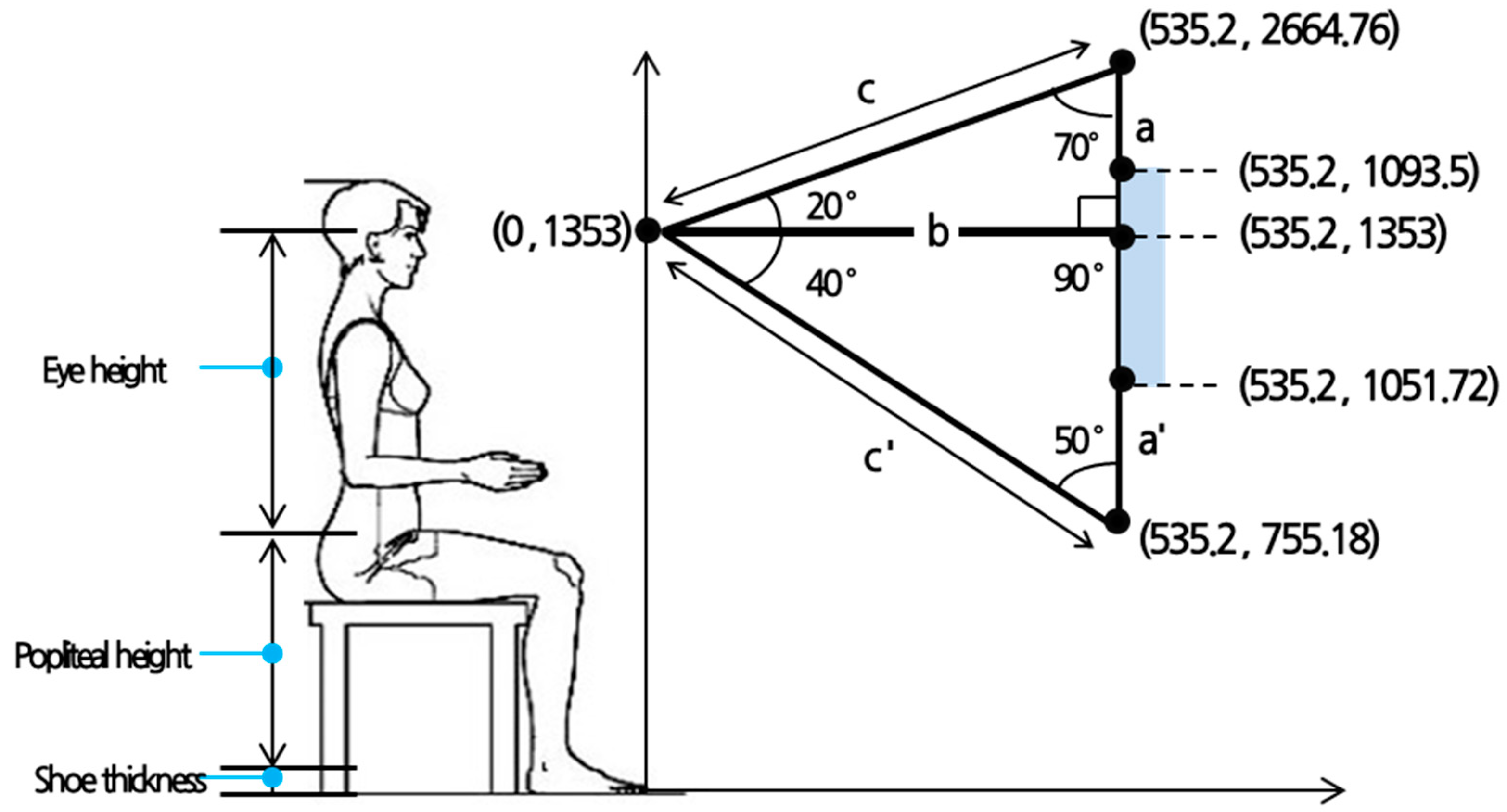
3.2. Anthropometric Data for Console Design and Ergonomic Issues in an MCR

As explained in the previous section, recent anthropometric data have to be considered for MCR operations. While there are similar MCR design tools, such as those detailed by Boring et al. [27], the proposed framework considers various anthropometric data. The Korean Agency for Technology and Standards’ 7th Korean Anthropometric Data Survey Report, which measured and investigated Koreans’ anthropometric data and human shapes in 2010 [28,29], were collected by console design factor item in this study for 10 months from March to December 2015. The anthropometric data of NPP operators aged 25–50 required for sit-down console evaluation were sorted and arranged by referring to the NUREG guidelines, as shown in Table 2 and Table 3.
The changes of anthropometric data indicate that the acceptable levels in MCRs at the design stage might be unacceptable and might cause several operational mistakes. This research considers the recent anthropometric data and evaluates an MCR with recently updated ergonomic criteria.
For the requirement analysis of designing a suitable operator console, there are several ergonomic issues to be resolved. First, proper anthropometric data should be applied. Since it may take several years for the redesign of the NPP MCR console due to human engineering deficiency, it is often difficult to apply the recent anthropometric data. Accordingly, it is also a difficult job to employ the recently redesigned drawings on time. Second, the suitability test of the console design based on human factor guidelines might not guarantee the accurate and reliable result, since it shows only part of the ergonomic test according to different evaluation methods. Third, the test result often lacks the persuasion for safety accreditation since the design guideline and review guideline are somehow different.
Therefore, modeling and simulation-based evaluation may be a better way to resolve the ergonomic issues on console design than guideline-based evaluation. The evaluation items with Korean male anthropometric data for sit-down console suitability in a digitalized MCR in an NPP are shown at Table 4.

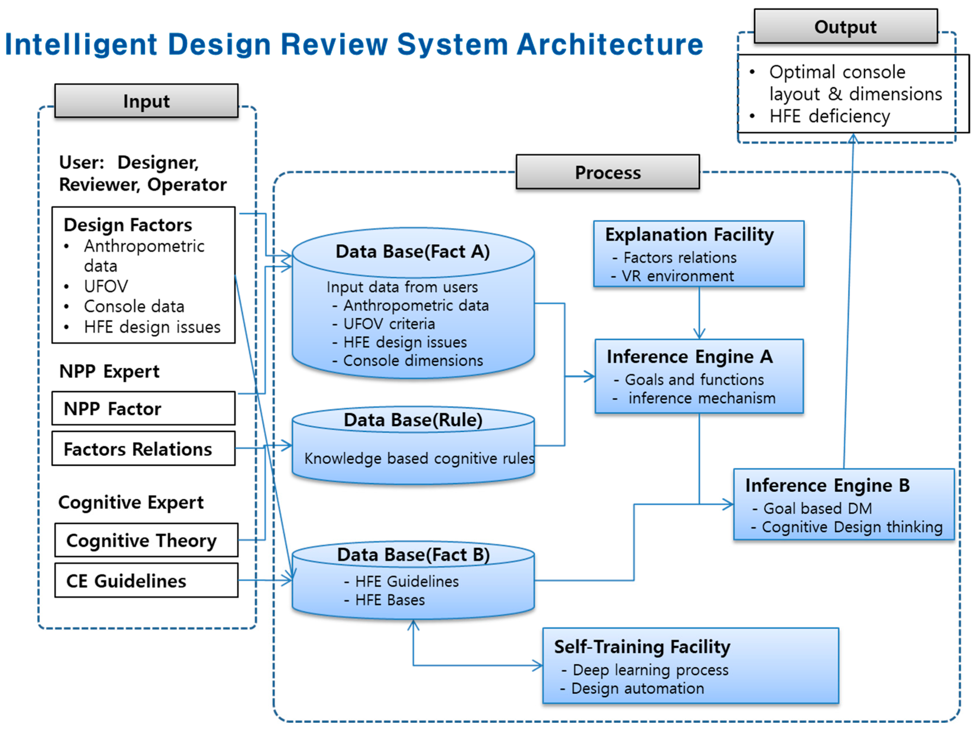
4. Intelligent MCR Design Review Framework using the Virtual Model

To carry out MCR design review and evaluation feedback efficiently, an intelligent design review system (IDRS), which is a virtual modeling and simulation facility with several intelligence functionalities, is developed in a demonstrative manner. The proposed IDRS complies with the testbed structure [8] of an intelligent system.

4.1. IDRS Building Blocks

A number of intelligent NPP interfaces have been developed. Lagari et al. [30] and Nasiakou et al. [31] provided fuzzy logic-based control interfaces. The intelligent design review system consists of several functions with some intelligence which has a cognitively oriented inference mechanism in addition to the traditional rule-based system elements shown in Figure 5. When a user (console designer or evaluator including NPP and cognitive experts) asks a question or inputs the design details (anthropometric data, console dimensions, workstation configuration, and so on) concerned through the given interface, an inference mechanism is triggered using the details in the database and rules for decision-making and the result is conveyed to the user through the cognitive interface. This study aims to improve the system design capability by employing an intelligence by which data can be more easily collected by adding a knowledge acquisition facility, a self-training facility providing optimal design criteria, and an explanation facility with a virtual environment to the architecture. In addition, the future research regarding ‘intelligent systems’ would be performed in a way to improve the intelligent functions’ operability by applying intelligent algorithms such as deep learning processes.

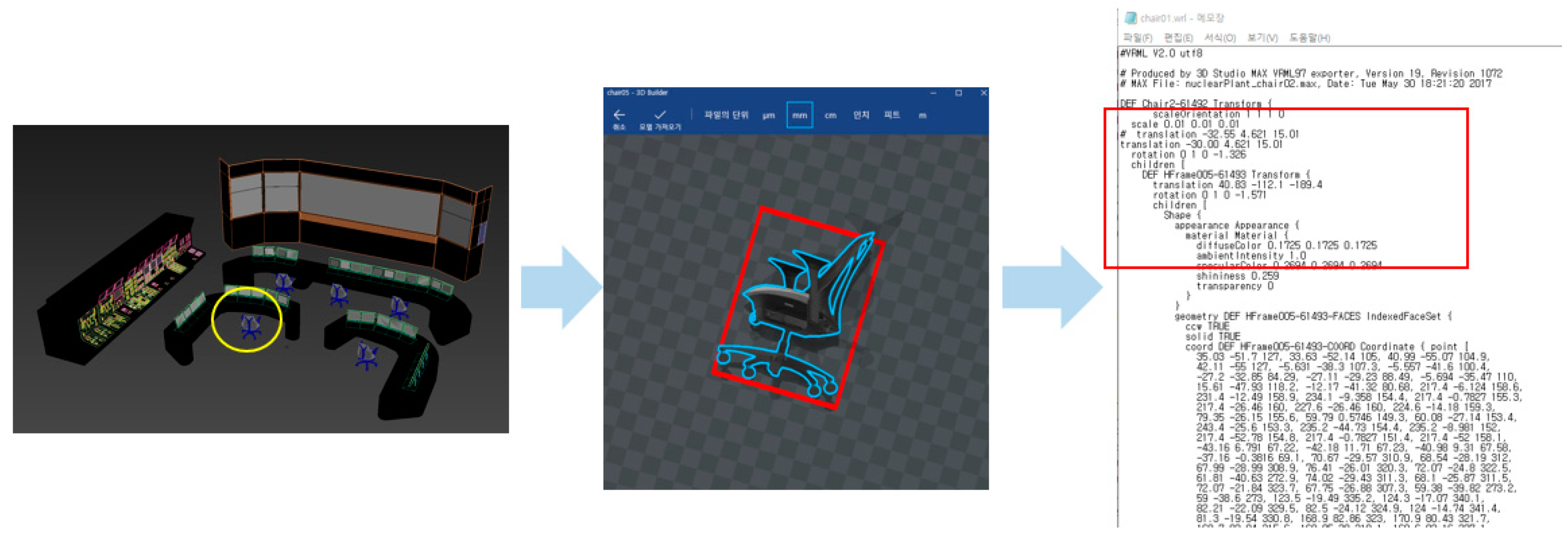
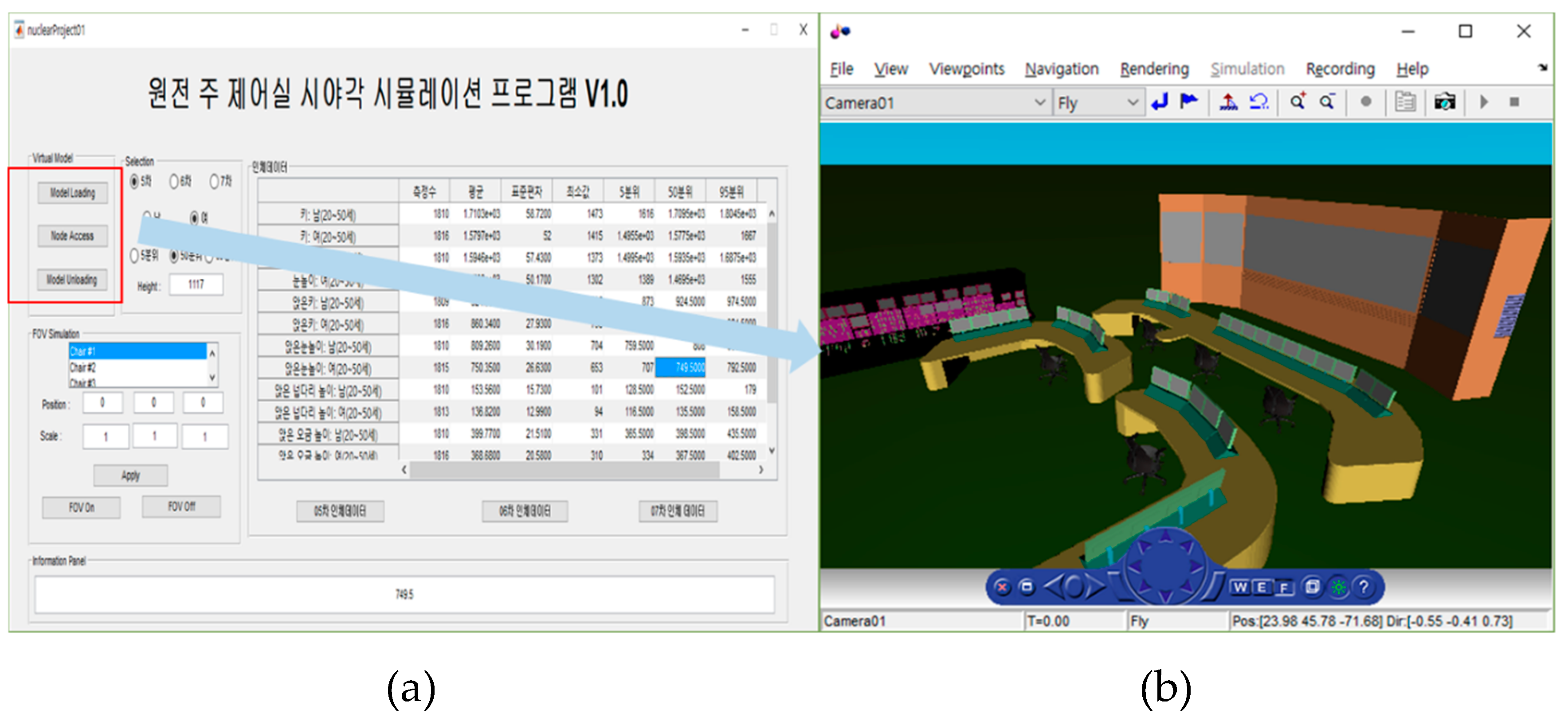
4.2. Virtual Model-Based Implementation of 2D–3D Design

The intelligent design review system has the powerful function of transforming the existing 2D drawing of an MCR to a 3D virtual model, as shown in Figure 6.
As the target MCR has a number of 2D drawings, the 3D virtual models are constructed using them. Table 5 shows the conversion process from 2D MCR drawings to the IDRS virtual model.
Moreover, each component in the MCR is represented parametrically for additional scaling, rotations, translation, and other transformations. Figure 7 shows the conversion process of a chair (the yellow mark in Figure 7) in an MCR with the parameter-based interoperable format, virtual reality modeling language (VRML). The chair is parameterized into each component shown the red box in Figure 7 and each components are represented using VRML language.
These functionalities are used for the simulation and evaluation of an MCR using the recent anthropometric data. For instance, a contemporary MCR uses 22′’ monitors, instead of the previously-used 19′’ monitors (Figure 8).
The implemented virtual model makes these transformations with the embedded parametric methods.

4.3. Virtual Model-Based Simulation and Evaluation for MCR Design Suitability

The Java-programmed testbed graphic user interface (GUI) for virtual modeling and simulation of designing and evaluating the MCR console is shown in Figure 9. Parameter inputs are crew position (Reactor Officer (RO), Turbine Officer (TO), Electric Officer (EO), Shift Supervisor (SS), Shift Technical Advisor (STA)), anthropometric data, view position (LDP, workstation), monitor size, safety console reachability, crew reachability, and so on.
The main ergonomic simulation and evaluations functionalities are summarized in Table 6.
As shown in Figure 9, the implemented framework loads several types of anthropometric data from the previous versions into the current version. The loaded data are used for the basic input data for the following ergonomic simulations and analyses. The following simulations mainly include ‘FOV simulations’ and ‘reachability analyses’. Simulation views for the operator’s field of view based on the computation model of the sit-down console are shown in Figure 10 and Figure 11.
The presented methodology is validated with the embedded geometric calculations. With the guideline mentioned in Section 4, the geometric models and calculations considering viewpoints and reachability are embedded in the implemented system. Currently, several Korean NPPs use the implemented system as a reference system for their MCR operations.
The implemented virtual model and the embedded simulation functionalities help to draw the more desirable MCR design specifications and recommendations. The implemented framework is used currently as a reference system for evaluating operators’ viewpoints and reachability in several Korean nuclear power plants. In particular, in the case of the employment of women as operators, the implemented system helps the prior analyses with their anthropometric data and recommends the changes of table and desk specifications (e.g., furniture heights and heights from the ground) according to their desired views and reachability. The developed system has the ability to load anthropometric data from an anthropometric database. This functionality can make it possible to use the system in several countries operating NPPs. The following section provides the design improvements and recommendations driven from the developed framework.

5. Design Improvement Results and Recommendations

In fact, it proved very difficult to find human engineering deficiencies in the console design, since too many factors were involved in meeting the design criteria based on human factor guidelines for the workstation design of the digitalized main control room in advanced nuclear power plants. An automated and virtual design review system such as the proposed IDRS can provide design efficiency and evaluation effectiveness. The modeling and simulation results from the IDRS showed some improvements regarding design and evaluation for the safety console and operator workstation. As shown in Figure 8, the IDRS made it very feasible to check the operators’ console reachability considering proper anthropometric data. As explained in the previous section, it would provide the design solution for the size change of operators’ monitor from the current 19” to the proposed 22”, which provided a better visual angle and more comfort in the working environment (Figure 12).
Another use of the VR-based system is to systematically find human engineering deficiencies of current standing safety consoles (see Figure 13). The simulation result found critical problems for functional reach suitability for the 5th percentile of females, while currently-used hands-on suitability check processes could not find out such problems nor provide accurate evidence to prove the inadequacy of the current design of the safety console. Based on this finding, the critical design change was made and system safety performance was improved with the systematic proven evidence. VR-based modeling and simulation with the IDRS can be used with confidence to overcome human engineering deficiencies for designing consoles.

6. Conclusions and Discussion

Safety has been the most important concern in a nuclear power plant (NPP). In a digital hybrid NPP, where the possibility of human errors has become higher due to increased cognitive load from more information, acquiring and/or missing the corrective information depends on the suitability of the MCR which consists of console-based workstations. While the existing research passively measures the regulations or the guidelines, this research proposed a new and efficient virtual model-based ergonomic simulation and evaluation framework considering the recent anthropometric data. Using the viewing angle-based evaluation support system applicable to the MCR design layout in an NPP through the results of this modeling and simulation study, we demonstrated the feasibility of designing and evaluating the console-based workstation and MCR environments efficiently in such a way to resolve the ergonomic issues on the usage of paper-based ergonomic guidelines.
The VR-based system showed contributions to uncover human engineering deficiencies from the current design of MCR consoles in a systematic manner and provide a feasible methodology for designing future consoles suitable for totally or partly digitalized MCRs in NPPs. Therefore, it is desirable to use VR-based modeling and simulation with the IDRS in order to assess human engineering deficiency for designing consoles.
From this study, work efficiency improvement would be expected within a digitalized main control room working environment, and there would be effectiveness in terms of ergonomics in the optimum design of a console depending on individual anthropometric data to be resolved. An intelligent design review system (IDRS), which is a virtual modeling and simulation facility, was developed in a demonstrative manner. However, system intelligence with self-training facility should be developed in a way to show more feasibility and adaptability to conventional console design.
This study could be applied for other human–machine systems, such as avionic, railroad, and automobile systems, which also have safety concerns and need systematic approaches to the design and evaluation of the working environment with various consoles. A VR-based system with the updated intelligent designing functions of the IDRS would surely provide more efficient and effective tools to design and evaluate the rapidly digitalized system.

Author Contributions

W.C.C. designed the research; W.C.C. performed research and analyzed the data; H.L. implemented the intelligent design review system; H.L. and W.C.C. wrote the paper; both authors read and approved the final manuscript.

Funding

This work was funded by grants 2015-104-125 from the Kumoh National Institute of Technology.

Acknowledgments

The author is grateful to the editors of this special issue and the three anonymous reviewers. Special thanks to members in KEPCO E&C Co. who supports the research study.

Conflicts of Interest

The authors declare no conflict of interest. The funders had no role in the design of the study; in the collection, analyses, or interpretation of data; in the writing of the manuscripts; or in the decision to publish the results.

References

  1. International Atomic Energy Agency (IAEA). Accident Analysis for Nuclear Power Plants. Available online: https://nucleus.iaea.org/sites/gsan/lib/Safety%20Assessment%20Safety%20Series/Accident%20Analysis%20for%20Nuclear%20Power%20Plants-SRS-23.pdf?Mobile=1&Source=%2Fsites%2Fgsan%2Flib%2F_layouts%2Fmobile%2Fview%2Easpx%3FList%3D2f739bb0%252D85b9%252D4fba%252Db5c3%252D6c457b2661b8%26View%3Dcf24c949%252D7312%252D4eda%252Db1a4%252Ded6747731de9%26CurrentPage%3D1 (accessed on 5 May 2019).
  2. Wheatley, S.; Sovacool, B.; Sornette, D. Of disasters and dragon kings: A statistical analysis of nuclear power incidents and accidents. Risk Anal. 2017, 37, 99–115. [Google Scholar] [CrossRef] [PubMed]
  3. United States Nuclear Regulatory Commission. NRC Regulatory Guides. Available online: https://www.nrc.gov/reading-rm/doc-collections/reg-guides/ (accessed on 5 May 2019).
  4. Cipollaro, A.; Lomonaco, G. Contributing to the nuclear 3S’s via a methodology aiming at enhancing the synergies between nuclear security and safety. Prog. Nucl. Energy 2016, 86, 31–39. [Google Scholar] [CrossRef]
  5. United States Nuclear Regulatory Commission. Control Room. Available online: https://www.nrc.gov/reading-rm/basic-ref/glossary/control-room.html (accessed on 5 May 2019).
  6. United States Nuclear Regulatory Commission. Highly Integrated Control Rooms-human Factors. Available online: https://www.nrc.gov/about-nrc/regulatory/research/digital/key-issues/control-room-human.html (accessed on 5 May 2019).
  7. United States Nuclear Regulatory Commission. Design Practices for Communications and Workstations in Highly Integrated Control Rooms. Available online: https://www.nrc.gov/reading-rm/doc-collections/nuregs/contract/cr6991/ (accessed on 5 May 2019).
  8. Cha, W.; Choi, E. A case study on designing a console design review system considering operators’ viewing range and anthropometric data. J. Ergon Soc Korea. 2017, 36, 373–383. [Google Scholar]
  9. Zheng, Z. Cognitive Load Measurement and Application; Routledge: New York, NY, USA, 2018. [Google Scholar]
  10. U.S. Nuclear Regulatory Commission. Cognitive Skill Training for Nuclear Power Plant Operational Decision Making (NUREC/CR-6126); Westinghouse Electric Corporation: Pittsburgh, PA, USA, 1994.
  11. Ra, D.W.; Cha, W.C. Development of Design Aiding System for the application of the Cognitive Interface for Information Displays. In Proceedings of the Ergonomics Society of Korea, UNIST, Ulsan, Korea, 23 May 2013. [Google Scholar]
  12. Boring, R.L.; Joe, J.C.; Ulrich, T.A.; Lew, R.T. Early-stage designed and evaluation for nuclear power plant control upgrades. In Proceedings of the Human Factors and Ergonomics Society 58th Annual Meeting, San Diego, CA, USA, 27–31 October 2014. [Google Scholar]
  13. Mu, Z.; Huang, R.; Liu, M. A study on the application of virtual reality technology in the field of nuclear power. In Proceedings of the 2017 International Conference on Smart Grid and Electrical Automation (ICSGEA), Changsha, China, 27–28 May 2017. [Google Scholar]
  14. Yan, G.; Li, M. Path planning and visualizing for maintenance simulation of nuclear power plant. Int. J. Online Eng. 2013, 9, 17–22. [Google Scholar] [CrossRef]
  15. Rodenas, J.; Zarza, I.; Burgos, M.C.; Felipe, A. Developing a virtual reality application for training nuclear power plant operators: Setting up a database containing dose rates in the refueling plant. Radiat. Prot. Dosim. 2004, 111, 173–780. [Google Scholar] [CrossRef] [PubMed]
  16. Wu, Y. Development and application of virtual nuclear power plant in digital society environment. Int. J. Energy Res. 2018, 43, 1521–1533. [Google Scholar] [CrossRef]
  17. Onitsuka, S.; Iijima, T.; Yamada, T.; Yoshimura, S. Seismic analysis of nuclear power plants by using three-dimensional finite element models: A review. J. Nucl. Sci. Technol. 2019, 56, 1–16. [Google Scholar] [CrossRef]
  18. Yoshimura, S.; Kobayashi, K.; Akiba, H.; Suzuki, S.; Ogino, M. Seismic response analysis of full-scale boiling water reactor using three-dimensional finite element method. J. Nucl. Sci. Technol. 2015, 4, 546–567. [Google Scholar]
  19. Jorge, C.; Mol, A.; Couto, P.; Pereira, C. Nuclear Power-Section 18 Nuclear plants and emergency virtual simulations based on a low-cost engine reuse, Nuclear Power, 1st ed.; Sciyo: Shanghai, China, 2010. [Google Scholar]
  20. Machado, D.M.; Cotelli, A.; Galvao, D.; Mol, A.C.A.; Carvalho, P.V.R.; Vidal, M. Use dosimetry virtual tool for security studies physics and nuclear. Procedia Manuf. 2015, 3, 1765–1771. [Google Scholar] [CrossRef]
  21. Xue, F.; Zhao, B.; Zhou, W.; Chen, L.; Wong, H. Computational egress and analysis for nuclear reactor building. In Proceedings of the 2018 International Conference on Computer Science and Application Engineering, Hohhot, China, 22–24 October 2018. [Google Scholar]
  22. Shen, Y.; Shen, H. The application of virtual reality technology to the conical roof lifting for the AP100 nuclear power plant. In Proceedings of the 2013 21st International Conference on Nuclear Engineering, Chengdu, China, 29–2 August 2013. [Google Scholar]
  23. Cao, Y.; Mo, Z.; Xiao, L.; Wang, H.; Ai, Z.; Zhang, Z. Efficient visualization of high-resolution virtual nuclear reactor. J. Vis. 2018, 21, 857–871. [Google Scholar] [CrossRef]
  24. Cha, W. Cognitive Interface; Kaos Book: Seoul, Korea, 2016. [Google Scholar]
  25. KEPCO E&C. Technical Report: Environment Design for Shingori 5&6; KEPCO E&C: Gimcheon, Korea, 2016; pp. 1–150. [Google Scholar]
  26. Nuclear Regulatory Commission. Human System Interface Design Review Guideline (NUREG-0700, Revision 2). Available online: https://www.nrc.gov/reading-rm/doc-collections/nuregs/staff/sr0700/ (accessed on 5 May 2019).
  27. Boring, R.L.; Dudenhoeffer, D.D.; Halbert, B.P.; Gore, B.F. Virtual power plant control room and crew modeling using MIDAS. In Proceedings of the workshop on future control station designs and human performance issues in nuclear power plants, Moulineaux, France, 15 October 2007. [Google Scholar]
  28. Korea Agency for Technology and Standard. 7th Korean Anthropometric Data Survey Report. Available online: http://www.sizekorea.kr (accessed on 5 May 2019).
  29. KEPCO E&C. Technical Report: Environment Design for Shingori 3&4; KEPCO E&C: Gimcheon, Korea, 2008; pp. 1–120.
  30. Lagari, P.L.; Nasiakou, A.; Alamaniotis, M. Evaluation of human machine interface (HMI) on a digital and analog control room in nuclear power plants using a fuzzy logic approach. Int. J. Monit. Surveill. Technol. Res. 2016, 4, 50–68. [Google Scholar] [CrossRef]
  31. Nasiakou, A.; Bean, R.; Alamaniotis, M. Development of human machine interface for digital control rooms in nuclear power plants. In Proceedings of the NPIC & HMIT, San Francisco, CA, USA, 11–15 June 2017. [Google Scholar]
  32. Lee, H.; Banerjee, A. A self-configurable large-scale virtual manufacturing environment for collaborative designers. Virtual Real. 2011, 15, 21–40. [Google Scholar] [CrossRef]
Figure 1. Example of a totally digitalized main control room (MCR) in a nuclear power plant (NPP): (a) Shin Kori NPP (SKN) 3; (b) the MCR in SKN 3.
Sustainability 11 02630 g001
Figure 2. Display height and orientation relative to a standing user’s line of sight [25,26].
Sustainability 11 02630 g002
Figure 3. Reach capability for a sit-down console [25,26].
Sustainability 11 02630 g003
Figure 4. Sit-down console design computational model with anthropometric data usage (male 95th percentile of the 7th Korean Anthropometric Data Survey Report [8].
Sustainability 11 02630 g004
Figure 5. Intelligent design review system process. HFE: human factors engineering; CE: cognitive engineering; VR: virtual reality; DM: decision making.
Sustainability 11 02630 g005
Figure 6. The implemented intelligent design review system (IDRS) virtual model): (a) 2D MCR drawings; (b) the implemented 3D MCR model.
Sustainability 11 02630 g006
Figure 7. Parametric conversion process of each component in the MCR.
Sustainability 11 02630 g007
Figure 8. Parametric conversion process of each component in the MCR.
Sustainability 11 02630 g008
Figure 9. IDRS user interface and anthropometric data loading.
Sustainability 11 02630 g009
Figure 10. Simulation result view 1: parameter changes of crew position and view position.
Sustainability 11 02630 g010
Figure 11. Simulation result view 2: anthropometric data view: (a) The implemented GUI based program; (b) the invoked 3D MCR module.
Sustainability 11 02630 g011
Figure 12. Design improvement result for console reachability check in the IDRS. The VR-based system proposed the monitor size change for better visual angle and comfort in the working environment (The y axis indicates heights and the x axis is the depth from the sitting point; unit: mm).
Sustainability 11 02630 g012
Figure 13. VR-based system simulation result showing human engineering deficiency for functional reach and suggested design change of the safety console. 5% female’s actual reach is deficient from 50% female (blue dashed).
Sustainability 11 02630 g013
Table 1. NPP applications using virtual models.
Virtual Model Application AreaResearch Studies and Systems
Operation guides for NPP controlsVirtual operator training [13]; Path planning and maintenance guiding simulation [14]; Refueling plant training [15]; Virtual roaming simulation and organ dose evaluation [16]
Emergency handling in an NPPSeismic analysis of an NPP [17,18]; Emergency path planning [19]; Security simulation [20]; Egress simulation [21]
Reference models for NPP constructionConical roof lifting for an NPP [22]; Reactor modeling [23]
Table 2. General ergonomic guidelines on visual fields.
ClassificationHorizontal Visual FieldVertical Visual Field
General rangeThe visual field range through which a subject can be viewed is 1° (to the left and right) when a central vertical axis is set up between the left and right eyes.In the vertical direction, the visual field tilts downwards more; The direction of the visual field is usually placed at 10° downwards.
Range in deciphering lettersSame visual field axis5–10° (left and right from the central axis)Centered on visual height horizonDesirable upward visual field limit is 15°
Range by which a symbol can be seen5–30° (left and right from the central axis)Upper limit: 20°
Lower limit: 30°
Range by which colors can be distinguished30–60° (left and right from the central axis)Upper limit: 30°
Lower limit: 40°
Table 3. Useful ergonomic design guidelines for MCR console design configuration and usability.
ClassificationUseful Guidelines for Design Configuration
Horizontal space standard of the control and display devicesAll the control and information display units used for the main jobs of a sit-down console should be placed within the maximum values of viewing range and extended reach of a user in the sitting-down position [26].
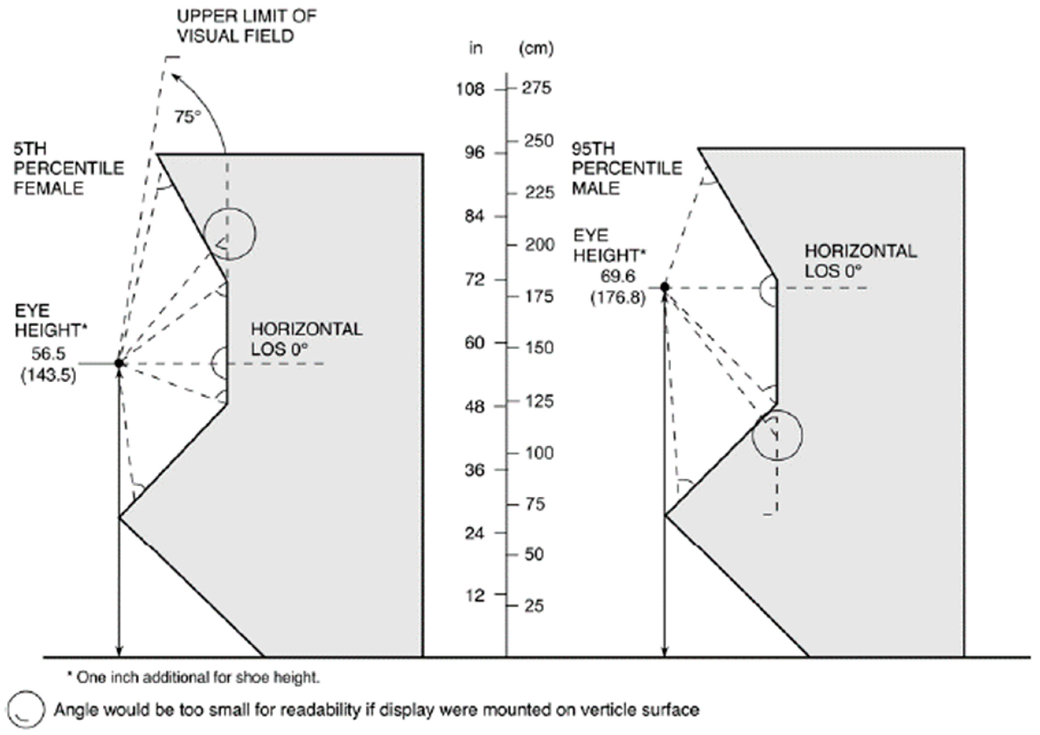
Standard of console visual display unit (VDU)’s vertical useful field of view (UFOV)In stand-up and sit-down consoles, all information display units, including an alarm indicator, need to be offered within the 5th percentile of a female’s field of view measurement (75° from horizontal field of view) [26].
The angle that the field of view and a visual display unit (VDU) forms needs to be maintained higher than 45° [26].
Actual layout range standard of VDU informationWhen main information display units were placed in a sit-down console, horizontal layout range was within 35° (to the left and right) centered on the line of sight (LOS) by using actual console shape data, with a vertical layout range designed to make the LOS 40° downwards [25,26,27].
The bench board slope, in conjunction with its depth, should be such that all controls are within the functional reach radius of the 5th percentile of females [25,26,27].
Controls should be set back a minimum of 3 inches from the front edge to protect against accidental contact [26].
Table 4. Sit-down console design evaluation items in the National Anthropometric Survey of Korean males, developed by the Korea Research Institute of Standards and Science in 2010 [Unit: cm].
No.Console Design Evaluation Item5%50%95%
1Stature161.4170.5179.9
2Eye height149.8159.0168.1
3Acromial height129.7138.2146.6
4Biacromial height36.339.943.2
5Finger height58.063.868.8
6Wall–finger distance75.982.688.7
7Sitting height87.392.497.4
8Eye height, sitting76.080.785.8
9Shoulder height, sitting55.559.864.2
10Elbow height, sitting22.426.230.0
11Forearm–fingertip length, sitting41.644.848.0
12Height of upper thigh when seated46.355.061.0
13Popliteal height36.539.743.3
14Buttock–knee length53.056.761.2
15Buttock–popliteal length42.346.551.0
16Hip breadth, sitting31.634.838.3
17Thigh clearance12.815.317.7
18Knee height39.843.847.7
Table 5. The conversion processes for the IDRS virtual model.
StageModel FormatUsed SoftwareSystem O.S.***Other Notes
2D drawing error checkPDFPDF viewer-PDF documents are given due to the security issue
3D CAD* conversiondwg/dxf/maxAutoDesk©
/Rhino©
--
Conversion to interoperable formatwrl3D Builder-Virtual reality modeling language (VRML) [32] format conversion
Integrated GUI dockingm/JavaOctav
/Matlab
/Java
Windows 10Java-based GUI** and Matlab-based calculation modules
3D simulation model wrl/m/JavaJavaWindows 10Integrated IDRS framework
*CAD: Computer Aided Design, ** GUI: Graphic User Interface, *** O.S.: Operation System.
Table 6. The embedding ergonomic simulation and evaluation functions.
Main CategoriesDetailed Functions
Anthropometric data interfaceAnthropometric database implementation (5th/6th/7th Korean Anthropometric Data Survey Reports); comparisons between both anthropometric data types; automatic calculation of ergonomic parameters (considering shoes and other factors)
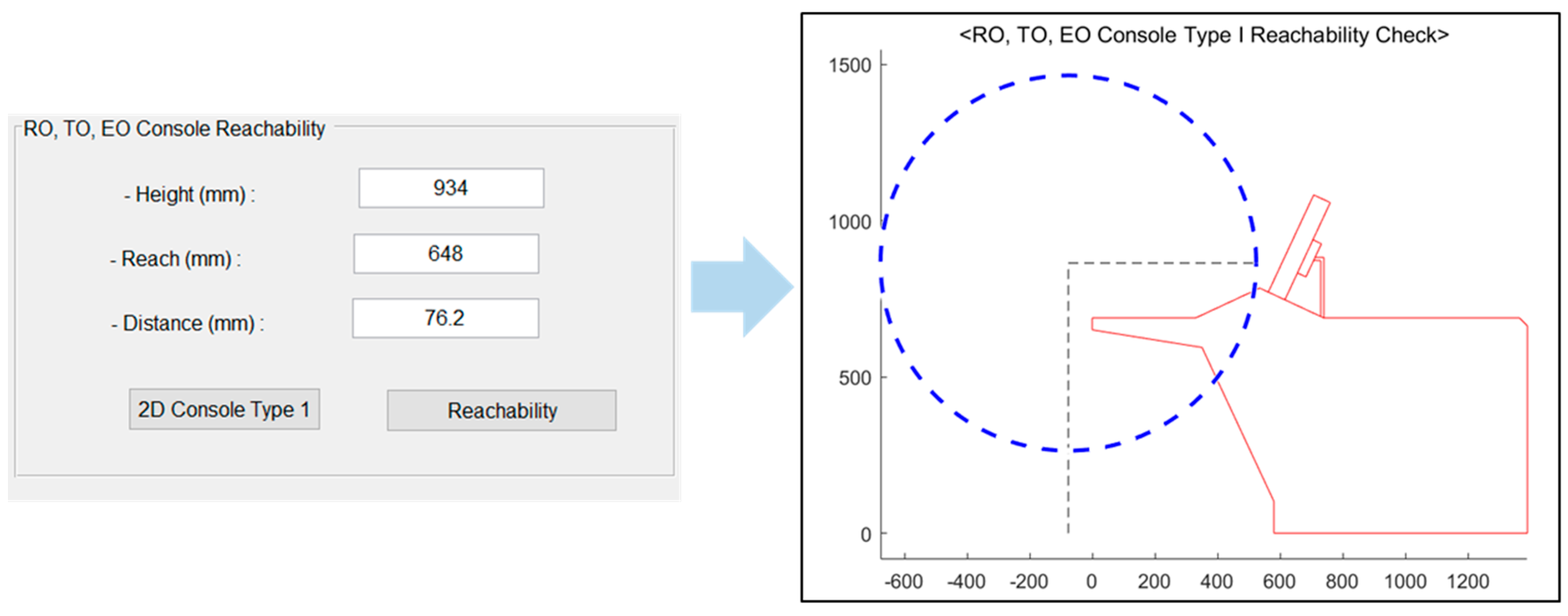
SimulationFOV simulation per each position (RO/TO/EO/SO/SS/STA); estimation of optimal view and maximum views; control range (reachability) calculation for Type I consoles (RO, TO, EO); control range (reachability) calculation for Type II consoles (SS, STA)
User interface (UI) changes and TransformationUI integrations/separations; parametric transformation for each component in the MCR

