Experimental Study of a New Strengthening Technique of RC Beams Using Prestressed NSM CFRP Bars

 ,
,
Abstract
:1. Introduction
2. Materials and Methods
2.1. Materials
2.1.1. Concrete
- Cement: The cement used to manufacture the concrete was pozzolanicThe actual density of the cement was determined by laboratory test [28] and the result obtained was 2.81 g/cm3.The mechanical characteristics were also calculated, manufacturing standardized mortar specimens (40x40x160mm), by means of kneading and mechanical compaction. The tests yielded a flexural strength of 6.8 N/mm2 and a compression resistance of 35.9 N/mm2.
- Aggregates: The sand and coarse aggregates used were crushed siliceous. The maximum size of the aggregates was 12.5 mm. The main characteristics of the sand and gravel that composed the aggregates used were as follows:
- ○
- Sand: The density of the sand was determined according to the standard [29], obtaining a result of 2.61 g/cm3. The sand equivalent was calculated according to the standard, obtaining a result of 84%. The granulometric analysis was carried out according to the standard [30]. The results obtained are shown in Table A1 (Appendix A).
- ○
- Gravel: The density of the gravel was determined according to the standard [29], with a result of 2.81 g/cm3. The results of the granulometric analysis are shown in Table A2 (Appendix A).
- Water: The water used in the mixture was drinking water from the public supply network in Madrid.
2.1.2. Steel
2.1.3. Epoxy Adhesives
- Flexion: 3 prismatic specimens with 4 × 4 × 16 dimensions were tested. An average result of 24 N / mm2 was obtained.
- Compression: After the flexion test, the test pieces were subjected to a compression test, obtaining an average of 93.22 N/mm2.
- Adhesion: Two prismatic mortar specimens of 10 × 10 cm cross section were used, arranged one after the other longitudinally, and separated by a 20 mm gap. A longitudinal slit was made on the underside of the specimens, in which a carbon fiber rod 8 mm in diameter, 20 cm long, was subsequently housed. The result was not conclusive, although it could be determined that the adhesion is sufficient to guarantee the transfer of loads.
- Flexion: 3 prismatic specimens with 4 × 4 × 16 dimensions were tested. An average result of 24 N/mm2 was obtained.
- Compression: After the bending test, the test pieces were subjected to a compression test, obtaining an average of 93.22 N/mm2.
- Adherence: Tests similar to those described for the MAXEPOX CS resin were performed, with similar results.
2.1.4. Carbon Fiber Rods
2.1.5. Fiber Fabric
2.1.6. Primer
2.2. Testing Campaign
- Batch A: Beams without reinforcement
- Batch B: Beams with passive reinforcement
- Batch C: Beams with active reinforcement.
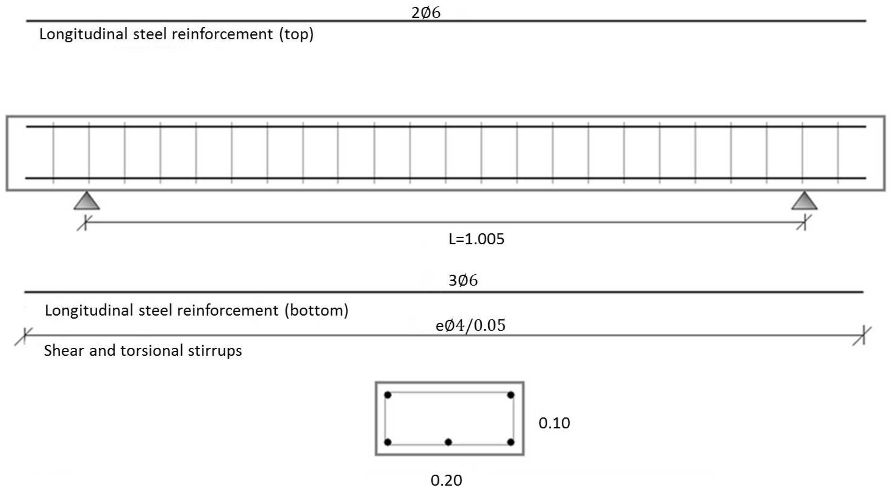
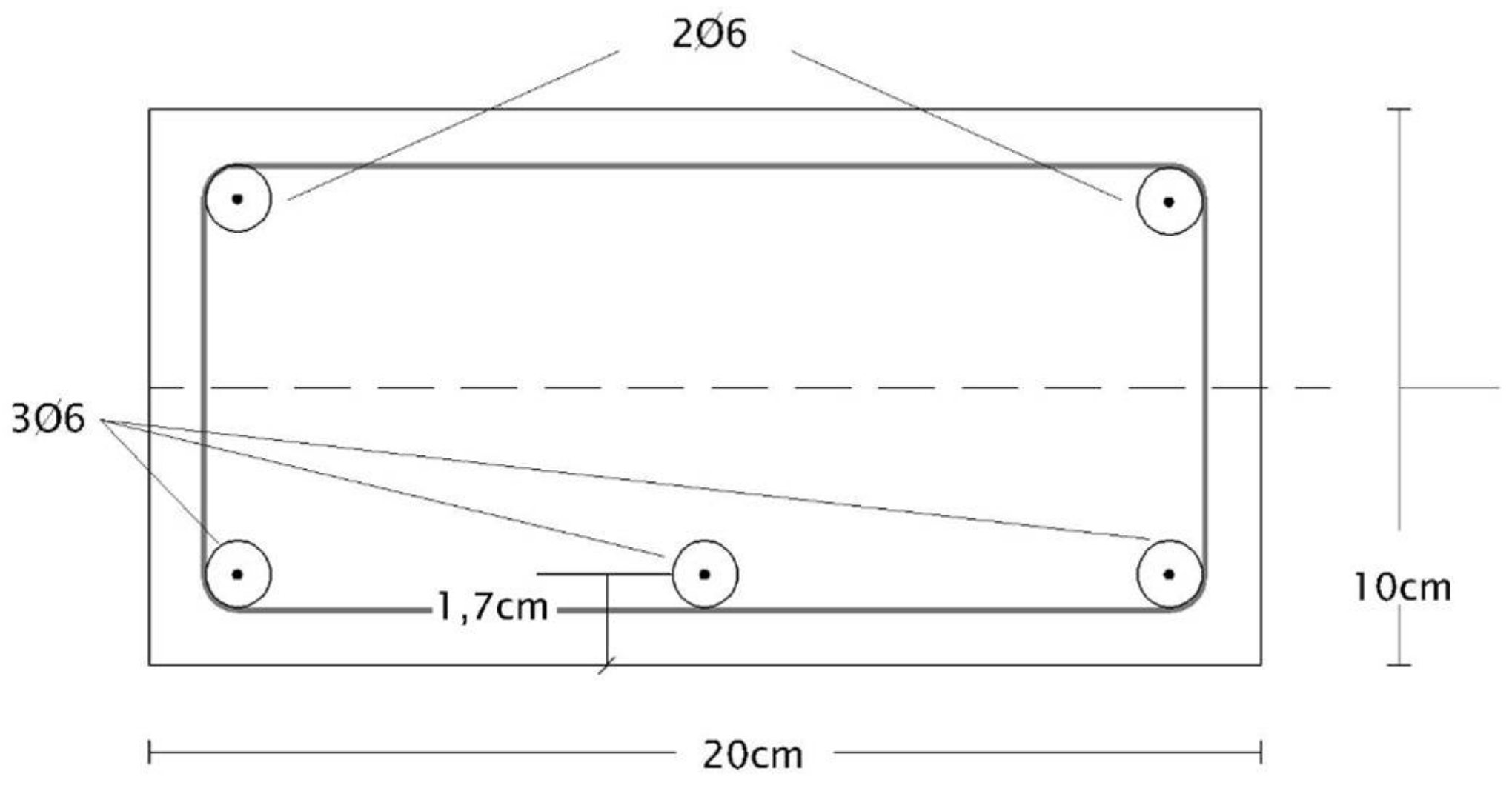
2.2.1. Beams Manufacturing
- Edge (h) = 10 cm
- Width (b) = 20 cm
- Coating (r) = 1.2 cm
- Cross section (bxh) = 200 cm2
- Area of the traction frame—3Ø6 mm (As) = 0.85 cm2
- Compression frame—2Ø6 mm (As′) = 0.57 cm2
- Transverse frame—Ø4 mm to 5cm
- Reinforcement area—2Ø8 (Ar) = 1.01 cm2
- Characteristic compression strength of concrete (fck) = 25.34 N/mm2
- Characteristic tensile strength of concrete (fctk) = 2.73 N/mm2
- Concrete elasticity modulus (Ec) = 30001.65 N/mm2 (according to tests)
- Steel elastic limit (fy) = 517.50 N/mm2 (according to tests)
- Steel elasticity modulus (Es) = 210000 N/mm2
- Reinforcement elasticity modulus (Er) = 150000 N/mm2
2.2.2. Beam Reinforcement
- Cracking moment: Mf = 1.1 KN-m and P = 6.6 KN.
- Momentum of ductile exhaustion of the beam without reinforcement: Mu = 3.18 KN-m and Pu = 19 KN
- Maximum momentum the beam can support before crushing the concrete in the compressed block: Mmax = 8.45 KN-m and Pmax = 50 KN.
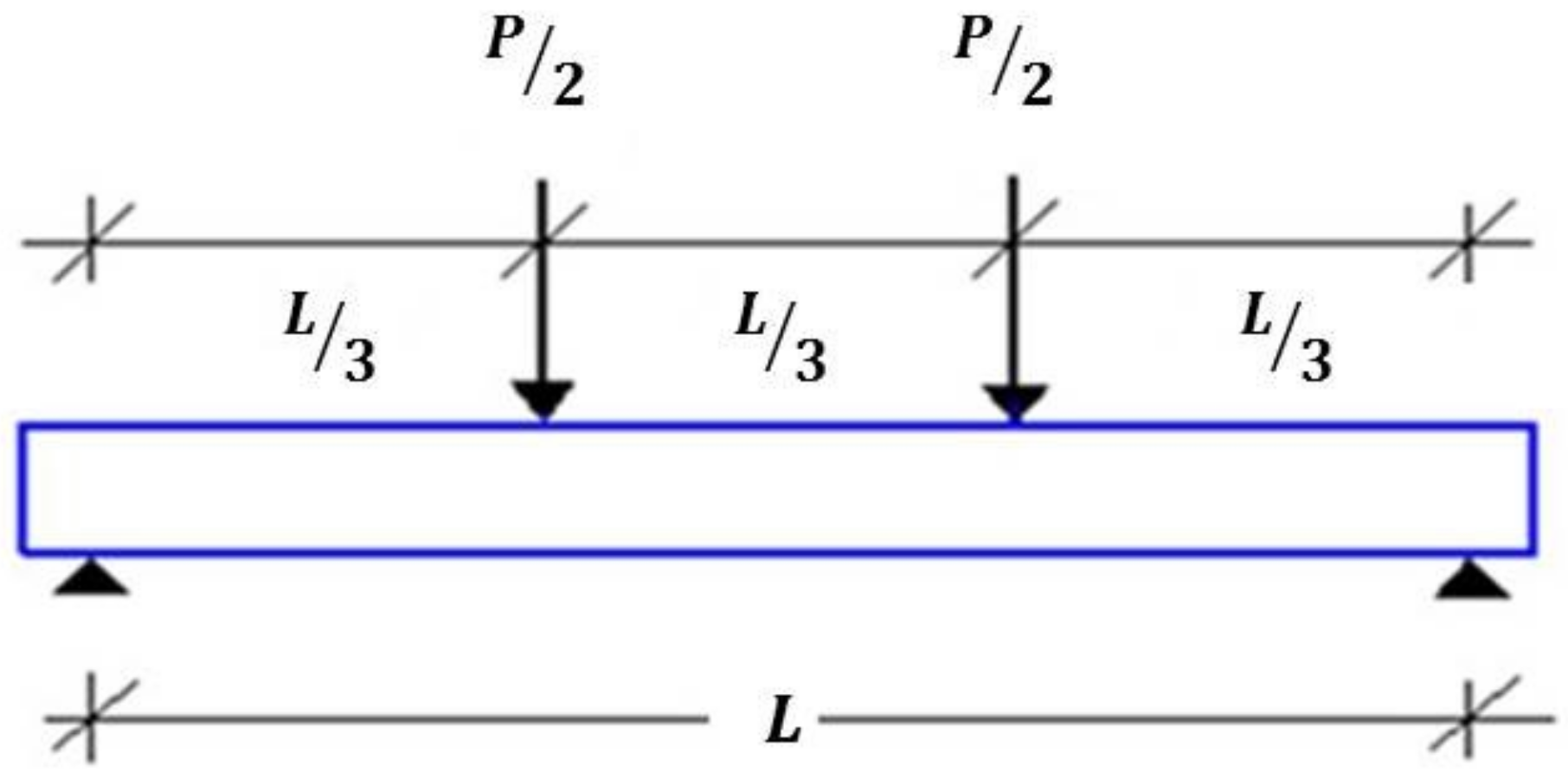
2.2.3. Flex Testing
3. Results and Discussion
3.1. Beams without Reinforcement (Batch A)
3.2. Beams with Passive Reinforcement (Batch B)
3.3. Beams with Active Reinforcement (Batch C)
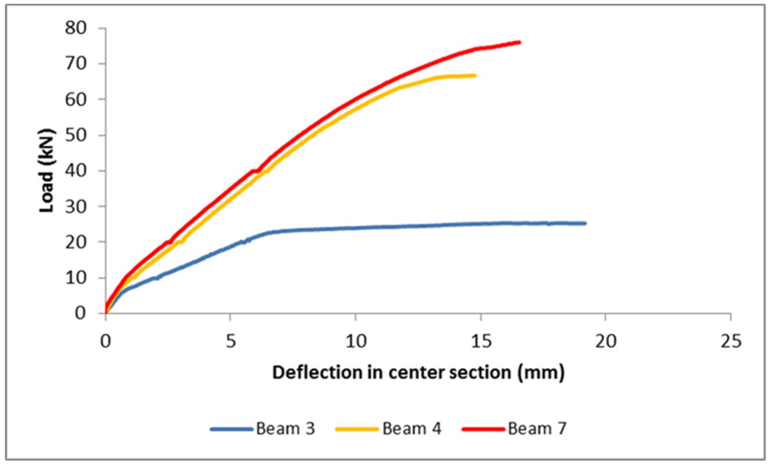
3.4. Comparative Results of the Flexural Tests of the Three Batches
4. Conclusions
- The introduction of preloads in reinforcement improves the mechanical behavior of the beam, thus making more efficient use of the characteristics of the reinforcement material. The active reinforcement supposes an increase of 170% of failure load with respect to the control beam.
- The introduction of preloads in the flexion reinforcement is complicated. Although it has been possible to achieve conditions close to those of a working site in the experiments, it will be necessary to improve the injection technique of the structural adhesive, to eliminate the cavities that appeared during the tests in beams from Batch C.
5. Patents
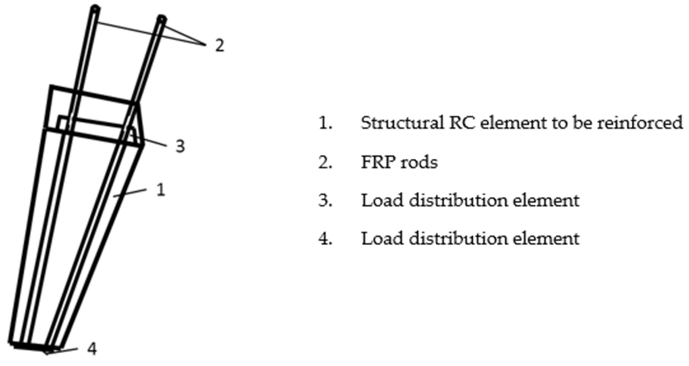
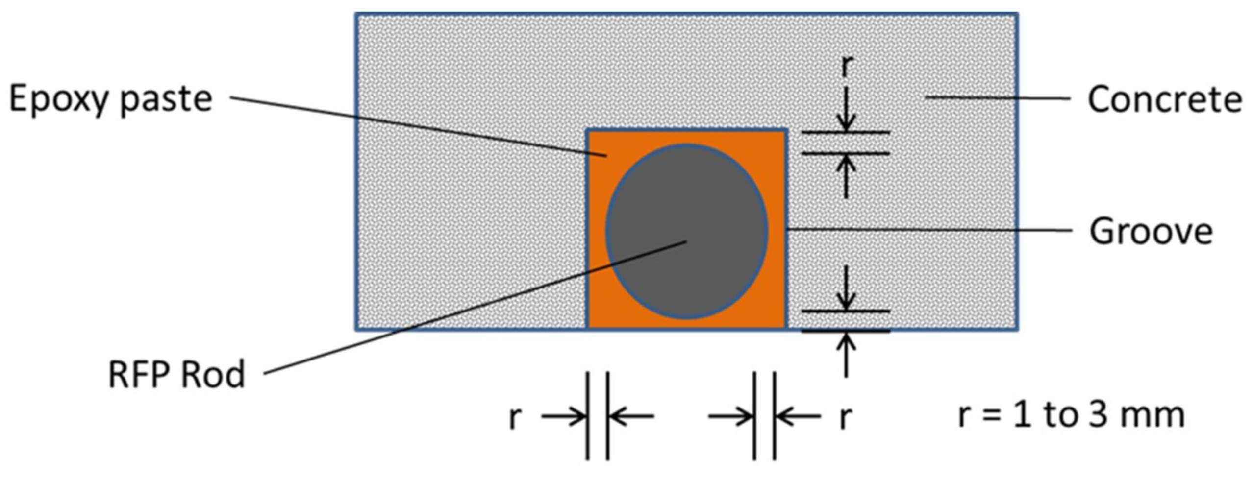
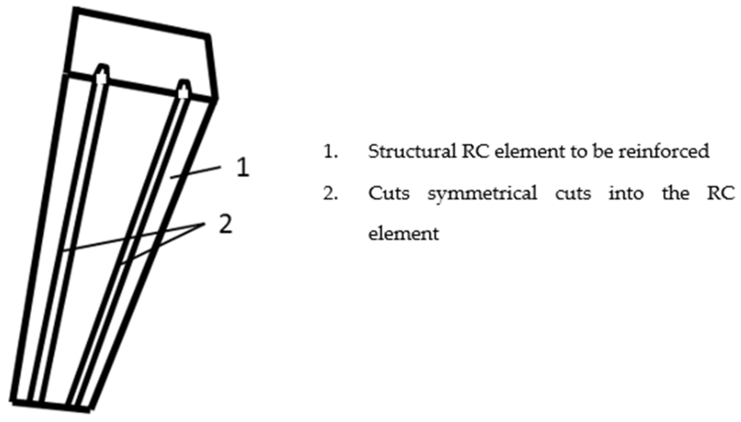
- The process begins by producing superficial straight cuts in the structural element of RC, with a depth equivalent to the shear and torsional stirrups, and the help of a radial tool. The symmetry has to be kept in line with the longitudinal axis of the structural element to be reinforced; in this case the longitudinal axis of the beam, as shown in Figure 6.
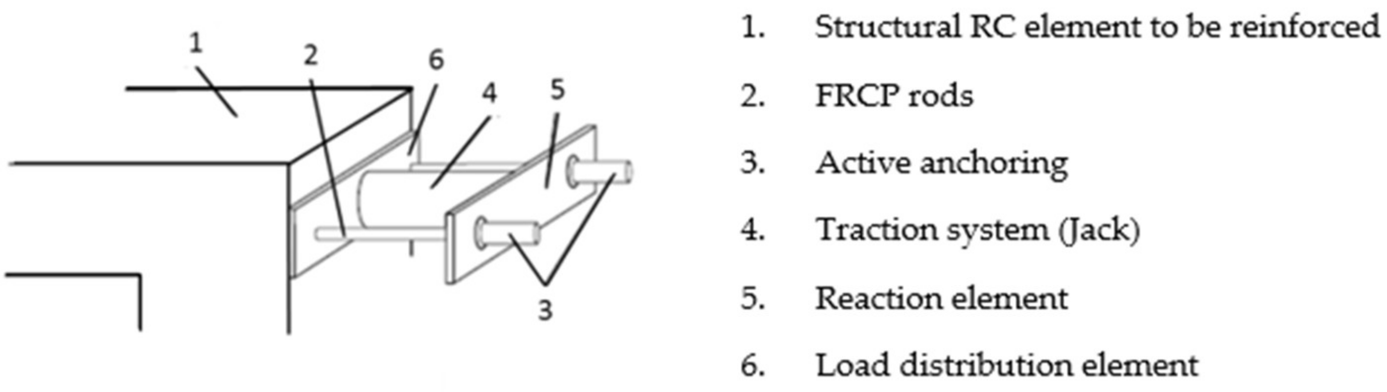
- Next, the FCRP rods are placed inside the cuts, together with load distribution elements (metal plates or similar) at each end, which will distribute the load received during the introduction of the pre-loads and thus avoid damaging the concrete, as shown in Figure 7.
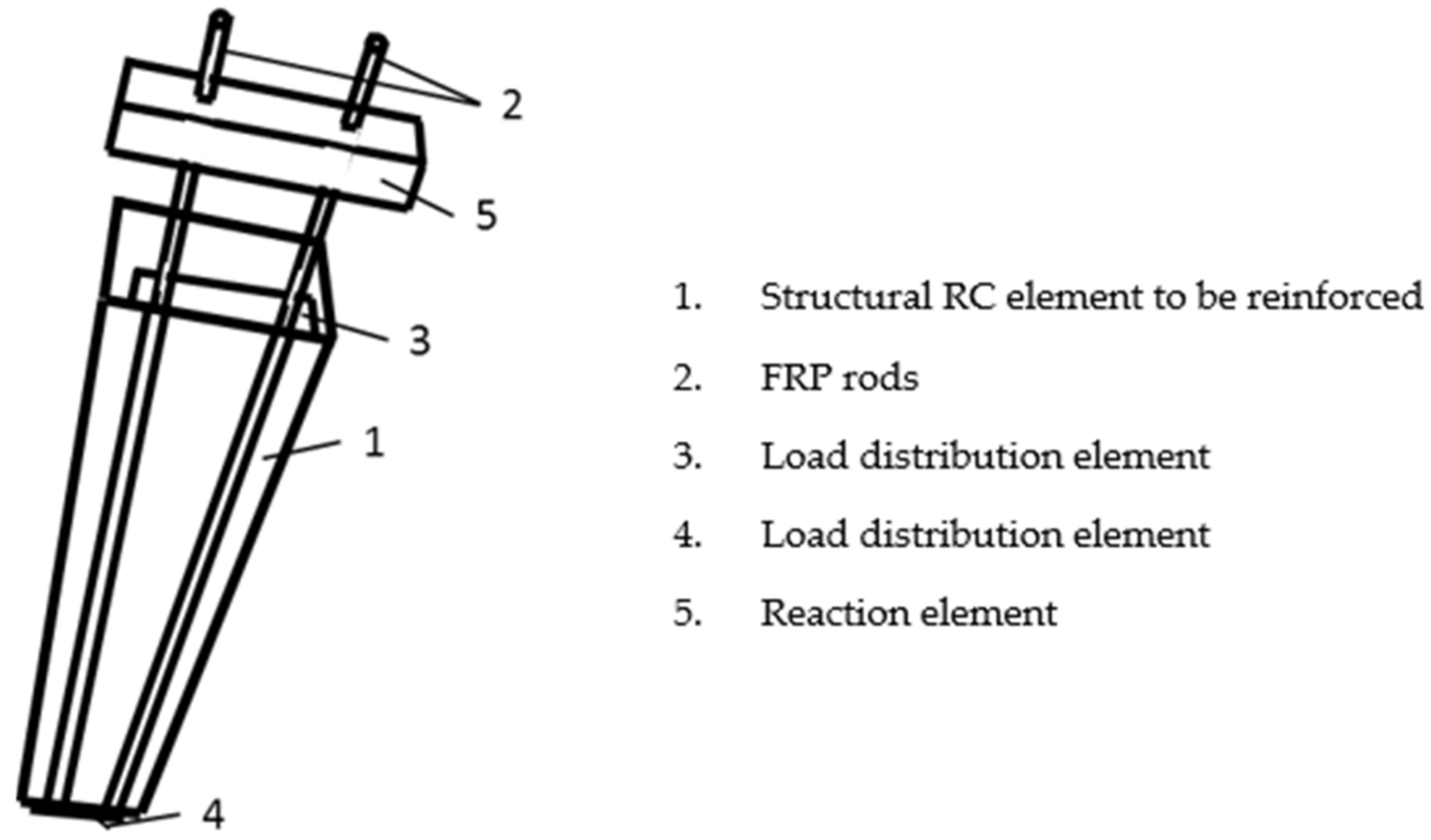
- A reaction element against which a traction system can push is put in place, as shown in Figure 8. Such an element must be very rigid and with perforations or grooves that are crossed by the FRP rods.
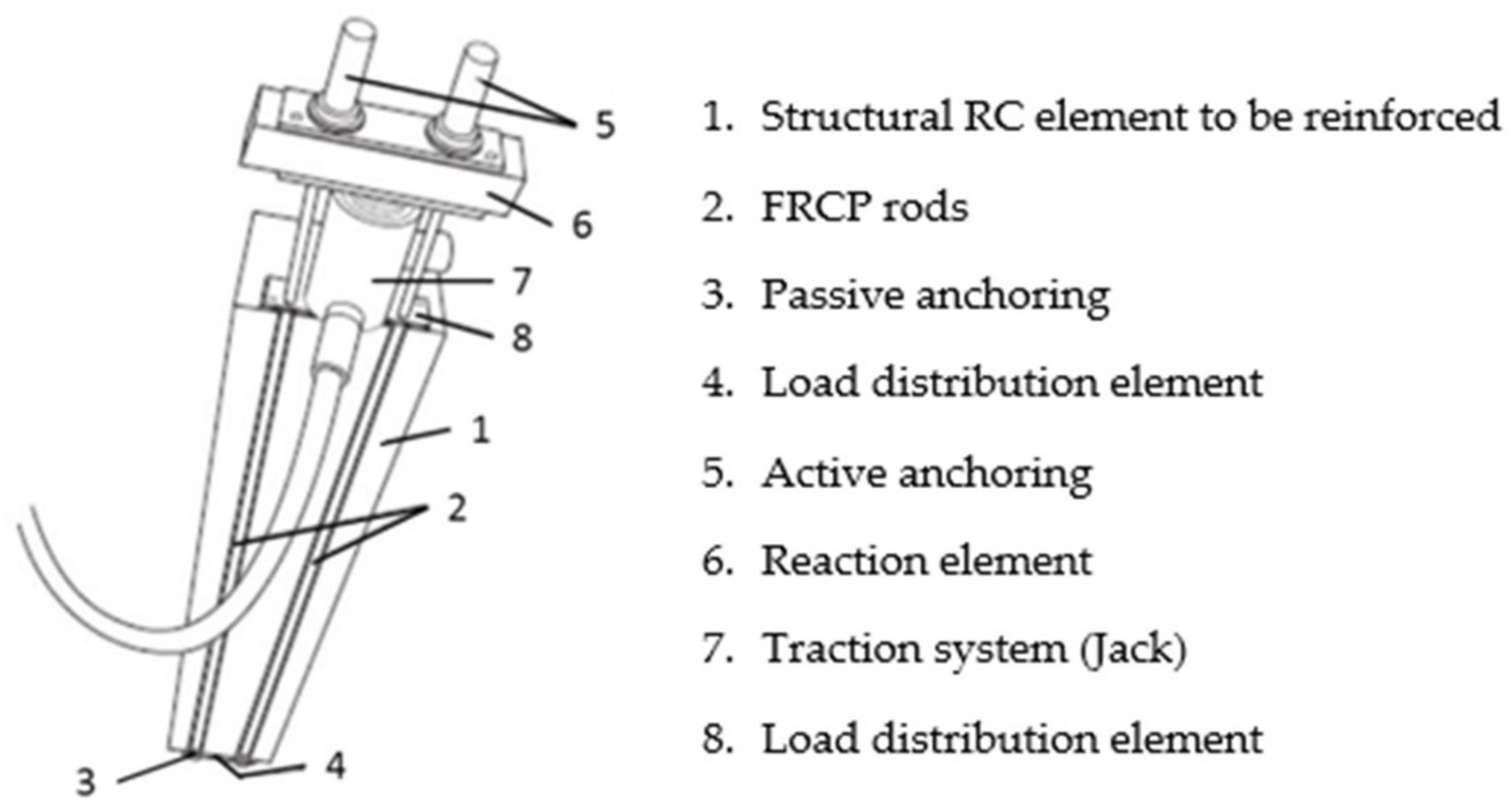
- The anchoring of the ends of the rods to immobilize them is achieved by means of a passive anchorage at one of the ends, and an active anchorage at the other end. They rely on the adhesion developed between the epoxy resin and the reinforcement rod. The anchor length is determined as a function of the pre-load that is intended to be introduced. In the first method, epoxy resin is injected into a copper tube of a diameter larger than the diameter of the FRP rod, placed perfectly centered at one end of the rod.
- After the rods are fixed, a traction system is placed, which can be a hydraulic jack or similar, as shown in Figure 9. Once balanced, the load begins to be applied, until the desired traction is obtained. Ideally the jack would have a pressure gauge to determine the preload introduced into the rods.
- To avoid the loss of load due to the relaxation of the traction system, it is preferable to immobilize the traction system and the pushing element against which the traction system pushes. This is achieved by placing at least one supplement that immobilizes the reaction element. In this way it is also possible to remove the traction system without the rods losing the load that has been introduced. In the tests carried out some wooden blocks were used, although certain load losses were recorded.
- Finally, the tensioned rods are glued along the entire connection to the structural element of concrete. For instance, epoxy resin can be used, by pouring it in the grooves in which the rods are located, and trying to completely fill the cuts made. Alternatively, it would also be possible to pre-fill the cuts in the structural element to be reinforced before placing the rods, to improve their filling.
- When the resin hardens, all the auxiliary elements (anchoring systems, load distribution plates, reaction system) can be removed. It will also be necessary to cut the protruding rods at both ends.
Author Contributions
Funding
Acknowledgments
Conflicts of Interest
Appendix A—Granulometric Analysis of the Sand and the Gravel Used in the Testing Campaign

| UNE Sieves (mm) | % Retained Sand | % Retained Sand Accumulated | % Accumulated Passing Sand |
|---|---|---|---|
| 32 | 0.00 | 0.00 | 100.00 |
| 16 | 0.00 | 0.00 | 100.00 |
| 8 | 0.00 | 0.00 | 100.00 |
| 4 | 1.48 | 1.48 | 98.52 |
| 2 | 17.18 | 18.67 | 81.33 |
| 1 | 34.27 | 52.94 | 47.06 |
| 0.5 | 22.30 | 75.24 | 24.76 |
| 0.25 | 16.63 | 91.87 | 8.13 |
| 0.125 | 6.80 | 98.67 | 1.33 |
| 0.063 | 1.33 | 100.00 | 0.00 |
| Granulometric module | 3.39 |
| UNE Sieves (mm) | % Retained Sand | % Retained Sand Accumulated | % Accumulated Passing Sand |
|---|---|---|---|
| 32 | 0 | 0 | 100 |
| 16 | 0 | 0 | 100 |
| 8 | 32.56 | 32.56 | 67.44 |
| 4 | 64.36 | 96.92 | 3.08 |
| 2 | 2.15 | 99.07 | 0.93 |
| 1 | 0.24 | 99.31 | 0.69 |
| 0.5 | 0.05 | 99.36 | 0.64 |
| 0.25 | 0.06 | 99.42 | 0.58 |
| 0.125 | 0.09 | 99.51 | 0.49 |
| 0.063 | 0.50 | 100 | 0 |
| Granulometric module | 6.26 |
References
- Aslam, M.; Shafigh, P.; Jumaat, M.Z.; Shah, S.N.R. Strengthening of RC beams using prestressed fiber reinforced polymers—A review. Constr. Build. Mater. 2015, 82, 235–256. [Google Scholar]
- Feng, Q.; Cui, J.; Wang, Q.; Fan, S.; Kong, Q. A feasibility study on real-time evaluation of concrete surface crack repairing using embedded piezoceramic transducers. Measurement 2018, 122, 591–596. [Google Scholar] [CrossRef]
- Qeshta, I.M.I.; Shafigh, P.; Jumaat, M.Z. A Research progress on the flexural behaviour of externally bonded RC beams. Arch. Civ. Mech. Eng. 2016, 16, 982–1003. [Google Scholar]
- Breveglieri, M.; Barros, J.; Dalfré, G.; Aprile, A. A parametric study about the effectiveness of the NSM technique for the flexural strengthening of continuous RC slabs. Compos. Part. B Eng. 2012, 43, 1970–1987. [Google Scholar]
- Ahmad, S. Reinforcement corrosion in concrete structures, its monitoring and service life prediction—A review. Cem. Concr. Compos. 2003, 25, 459–471. [Google Scholar]
- Abdelrahman, A.A.; Rizkalla, S.H. Serviceability of concrete beams prestressed by carbon-fiber-reinforced-plastic bars. ACI Struct. J. 1997, 94, S42. [Google Scholar]
- De-Lorenzis, L.; Teng, J. Near-surface mounted FRP reinforcement: An emerging technique for strengthening structures. Compos. Part. B Eng. 2007, 38, 119–143. [Google Scholar]
- Khalifa, A.; Alkhrdaji, T.; Nanni, A.; Lansburg, S. Anchorage of surface mounted FRP reinforcement. Concr. Int. Des. Constr. 1999, 21, 49–54. [Google Scholar]
- Yost, J.; Gross, S.; Dinehart, D.; Mildenberg, J. Flexural behavior of concrete beams strengthened with near-surface-mounted CFRP strips. ACI Struct. J. 2007, 104, 430–437. [Google Scholar]
- El-Hacha, R.; Riskalla, S. Near-surface-mounted fiber-reinforced polymer reinforcements for flexural strengthening of concrete structures. ACI Struct. J. 2004, 101, 717–726. [Google Scholar]
- Soliman, S.; El-Salakawy, E.; Benmokrane, B. Flexural behaviour of concrete beams strengthened with near surface mounted fibre reinforced polymer bars. Can. J. Civ. Eng. 2010, 37, 1371–1382. [Google Scholar] [CrossRef]
- De-Lorenzis, L.; Nanni, A. Bond between near-surface mounted FRP rods and concrete in structural strengthening. ACI Struct. J. 2002, 99, 123–132. [Google Scholar]
- Hassan, T.; Rizkalla, S. Investigation of Bond in Concrete Structures Strengthened with Near Surface Mounted Carbon Fiber Reinforced Polymer Strips. J. Compos. Constr. 2003, 7, 248–257. [Google Scholar] [CrossRef]
- Hassan, T.; Rizkalla, S. Bond Mechanism of NSM FRP Bars for Flexural Strengthening of Concrete Structures. ACI Struct. J. 2004, 101, 830–839. [Google Scholar]
- Chalioris, C.E.; Kosmidou, P.K.; Papadopoulos, N.A. Investigation of a New Strengthening Technique for RC Deep Beams Using Carbon FRP Ropes as Transverse Reinforcements. Fibers 2018, 6, 52. [Google Scholar] [CrossRef]
- Kim, Y.J.; Heffernan, P.J. Fatigue behavior of externally strengthened concrete beams with fiber-reinforced polymers: State of the art. J. Compos. Constr. 2008, 12, 246–256. [Google Scholar] [CrossRef]
- Luizaga, A.M. Comportamiento Mecánico de Vigas de Hormigón Reforzadas con Bandas Encoladas con Resinas Epoxídicas. Ph.D. Thesis, Universidad Politécnica de Madrid, Madrid, Spain, 2005. [Google Scholar]
- Nordin, H.; Taljsten, B. Concrete beams strengthened with prestressed near surface mounted CFRP. J. Compos. Constr. 2006, 10, 60–68. [Google Scholar] [CrossRef]
- Meier, U. Strengthening of structures using carbon fibre/epoxy composites. Constr. Build. Mater. 1995, 9, 341–351. [Google Scholar] [CrossRef]
- El-Hacha, R.; Gaafar, M. Flexural strengthening of reinforced concrete beams using prestressed, near-surface-mounted CFRP bars. PCI J. 2011, 56, 134–151. [Google Scholar] [CrossRef]
- Oudah, F.; El-Hacha, R. Analytical fatigue prediction model of RC beams strengthened in flexure using prestressed FRP reinforcement. Eng. Struct. 2013, 46, 173–183. [Google Scholar] [CrossRef]
- Badawi, M.; Soudki, K. Flexural strengthening of RC beams with prestressed NSM CFRP rods—Experimental and analytical investigation. Constr. Build. Mater. 2009, 23, 3292–3300. [Google Scholar] [CrossRef]
- Rezazadeh, M.; Ramezansefat, H.; Barros, J. NSM CFRP Prestressing Techniques with Strengthening Potential for Simultaneously Enhancing Load Capacity and Ductility Performance. J. Compos. Constr. 2016, 20, 04016029. [Google Scholar] [CrossRef]
- Rezazadeh, M.; Barros, J.; Costa, I. Analytical approach for the flexural analysis of RC beams strengthened with prestressed CFRP. Compos. Part B Eng. 2015, 73, 16–34. [Google Scholar] [CrossRef]
- Choi, H.T.; West, J.S.; Soudki, K.A. Effect of partial unbonding on prestressed nearsurface- mounted CFRP-strengthened concrete T-Beams. J. Compos. Constr. 2010, 15, 93–102. [Google Scholar] [CrossRef]
- Hajihashemi, A.; Mostofinejad, D.; Azhari, M. Investigation of RC beams strengthened with prestressed NSM CFRP laminates. J. Compos. Constr. 2011, 15, 887–895. [Google Scholar] [CrossRef]
- Rezazadeh, M.; Costa, I.; Barros, J. Influence of prestress level on NSM CFRP laminates for the flexural strengthening of RC beams. Compos. Struct. 2014, 116, 489–500. [Google Scholar] [CrossRef]
- Instituto Nacional de Racionalización y Normalización. UNE 80-103-86: Métodos de Ensayo de Cementos: Ensayos Físicos: Determinación de la Densidad real Mediante el Volumenómetro de Le Chatelier; IRANOR: Madrid, Spain, 1986. [Google Scholar]
- Instituto Nacional de Racionalización y Normalización. UNE-EN 1097-6:2014: Tests for Mechanical and Physical Properties of Aggregates—Part 6: Determination of Particle Density and Water Absorption; AENOR: Madrid, Spain, 2014. [Google Scholar]
- Instituto Nacional de Racionalización y Normalización. UNE-EN 12620:2003: Aggregates for Concrete; AENOR: Madrid, Spain, 2003. [Google Scholar]
- Instituto Nacional de Racionalización y Normalización. UNE 83301:1991: Tests of Concrete. Making and Curing of Specimens; AENOR: Madrid, Spain, 1991. [Google Scholar]
- Instituto Nacional de Racionalización y Normalización. UNE-EN 12390-3:2003: Testing Hardened Concrete—Part 3: Compressive Strength of Test Specimens; AENOR: Madrid, Spain, 2003. [Google Scholar]


| Material | Density (kg/m3) | Dosage (m3) | Dosage (kg) |
|---|---|---|---|
| Concrete | 2810 | 131 | 370 |
| Sand | 2610 | 214 | 560 |
| Gravel | 2810 | 427 | 1200 |
| Water | 1000 | 235 | 235 |
| Concrete density = 2350 kg/m3 | |||
| Water / cement ratio = 0.64 | |||
| Test Specimen Number | Weight (kg) | Density of Hardened Concrete (g/cm3) | Maximum Load (T) | Compression Resistance (N/mm2) |
|---|---|---|---|---|
| 1 | 12.40 | 2.34 | 32.89 | 18.61 |
| 2 | 12.48 | 2.35 | 41.11 | 23.27 |
| 3 | 12.39 | 2.34 | 40.90 | 23.15 |
| 4 | 12.49 | 2.36 | 38.19 | 21.61 |
| Field | Value | Unit |
|---|---|---|
| Test speed | 0.50 | kN/s |
| Section of the test piece | 28.27 | mm2 |
| Maximum applied force | 32.96 | kN |
| Elastic limit (fy) | 517.5 | N/ mm2 |
| Elasticity module (E) | 184,816.7 | N/ mm2 |
| Elongation remaining after rupture | 55.55 | Mm |
| Lower yield limit | 559.6 | N/ mm2 |
| Upper yield limit | 566.1 | N/ mm2 |
| Appearance and color | Rod of black color and rough surface | ||
| Diametre (mm) | 8 | 10 | 12 |
| Steel equivalent diameter B-500 | 14 | 16 | 20 |
| Cross-sectional area (mm2) | 50 | 78 | 110 |
| Guaranteed traction load (kN) | 100 | 156 | 220 |
| Recommended design load (kN) | 70 | 109 | 154 |
| Recommended tensile strength design (MPa) | 1400 | ||
| Length (m) | 3.00 | ||
| Characteristic tensile strength (MPa) | 2000 | ||
| Elasticity module (MPa) | 150,000 | ||
| Deformation in breakage (%) | >1.33 | ||
| Sheet width (m) | 0.33 |
| Sheet density (g/mm2) | 300 |
| Thickness (mm) | 0.163 |
| Tensile strength (N/mm2) | 2400 |
| Elasticity module (N/mm2) | 4.4 × 10⁵ |
| Break elongation (‰) | 5.5 |
| Thickness (mm) | 0.163 | 0.727 | 0.890 |
| Tensile strength (N/mm2) | 2400 | 29 | 444 |
| Elasticity module (N/mm2) | 4.4 × 10⁵ | 0.015 × 10⁵ | 0.81 × 10⁵ |
| Temperature of employment | 15–35 °C | |
| Appearance | Main agent | Pale liquid |
| Hardener | Pale yellow liquid | |
| Proportion of the mixture: | ||
| In weigh (A:B) In volume (A:B) | 4:1 100:28 | |
| Specific weight (25 °C) | Main agent | 1.15 |
| Hardener | 0.96 | |
| Life time in container (min) | 30 °C 25 °C 15 °C | 90 min 130 min 180 min |
| Open time (h) | 30 °C 25 °C 15 °C | 8.0 11.0 17.0 |
| Viscosity | 30 °C 25 °C 15 °C | 200 320 750 |
| Performance (Kg/m2) | 0.25 | |
| Adherence to concrete | 1.5 N/mm2 | |
| Batch | Beam | Cracking | Elastic-Cracked | Depletion | ||
|---|---|---|---|---|---|---|
| Load (kN) | Deflection (mm) | Load (kN) | Deflection (mm) | Load (kN) | ||
| Batch A | V-1 | 5.7 | 0.37 | 21.8 | 5.64 | 28.0 |
| V-2 | 5.7 | 0.8 | 20.9 | 6.68 | 25.7 | |
| V-3 | 4.6 | 0.49 | 21.1 | 5.87 | 25.3 | |
| Theoretical | 5.4 | 0.34 | 14.9 | 7.09 | 18.1 | |
| Batch B | V-4 | 6.4 | 0.52 | 61.2 | 11.08 | 63.0 |
| V-5 | 4.4 | 0.38 | 44.1 | 7.76 | 48.0 | |
| V-6 | 6.0 | 0.48 | 49.0 | 9.21 | 51.0 | |
| Theoretical | 5.5 | 0.33 | 33.0 | 15.7 | ||
| Batch C | V-7 | 8.7 | 0.67 | 73.3 | 14.43 | 75.6 |
| V-8 | 8.5 | 0.41 | 47.8 | 8.27 | 51.5 | |
| V-9 | NA | NA | 64.1 | 13.17 | 64.4 | |
| Theoretic | 6.9 | 0.41 | 34.3 | 16.4 | ||
© 2019 by the authors. Licensee MDPI, Basel, Switzerland. This article is an open access article distributed under the terms and conditions of the Creative Commons Attribution (CC BY) license (http://creativecommons.org/licenses/by/4.0/).
Share and Cite
Alcaraz Carrillo de Albornoz, V.; García del Toro, E.M.; Más-López, M.I.; Luizaga Patiño, A. Experimental Study of a New Strengthening Technique of RC Beams Using Prestressed NSM CFRP Bars. Sustainability 2019, 11, 1374. https://doi.org/10.3390/su11051374
Alcaraz Carrillo de Albornoz V, García del Toro EM, Más-López MI, Luizaga Patiño A. Experimental Study of a New Strengthening Technique of RC Beams Using Prestressed NSM CFRP Bars. Sustainability. 2019; 11(5):1374. https://doi.org/10.3390/su11051374
Chicago/Turabian StyleAlcaraz Carrillo de Albornoz, Vicente, Eva M. García del Toro, M. Isabel Más-López, and Alfredo Luizaga Patiño. 2019. "Experimental Study of a New Strengthening Technique of RC Beams Using Prestressed NSM CFRP Bars" Sustainability 11, no. 5: 1374. https://doi.org/10.3390/su11051374
APA StyleAlcaraz Carrillo de Albornoz, V., García del Toro, E. M., Más-López, M. I., & Luizaga Patiño, A. (2019). Experimental Study of a New Strengthening Technique of RC Beams Using Prestressed NSM CFRP Bars. Sustainability, 11(5), 1374. https://doi.org/10.3390/su11051374