1. Introduction
Longwall mining is the most common underground mining method in the world [
1,
2,
3]. With the reduction of coal resources, there are problems in traditional underground coal mining, such as unaffordable driving costs, large surface disturbances, low coal-extraction rates, and the frequent occurrence of safety accidents. Such issues have also been addressed in the literature [
4,
5,
6,
7]. Following the development path of environment-friendly, safe, high-efficient, non-pillar mining technology, it has been widely used in coal mining. Gob-side entry retaining is a common practice of non-pillar mining in mine shafts, which significantly improves the coal recovery rate, reduces the roadway excavation, allows for the Y-type ventilation on the mining face, and addresses the gas accumulation at the corners of the working surface [
8,
9,
10].
However, the gob-side entry retaining introduces various drawbacks as a result of coal (rock) pillar retaining, such as stress concentration in the surrounding rock and high risk of gas explosion in the gob zone. Non-coal pillar mining with roadway formed automatically (RFANM) is a new mining technology with no request required for excavating roadways in advance and with coal retaining pillar, which avoids various hazards as a result of coal (rock) pillar retaining and allows for safe and efficient coal production [
11,
12].
The main roof breaks in the form of blocks into the gob zone. This breaking process is affected by factors such as the effect of the roof pre-cracking slit and the strength of the roadway support; there may be multiple occasional breaks in the main roof. Depending upon the locations of the fractures, the extent and severity of the rotation and subsidence of key rock blocks are different, which has a great influence on the stability of roadway.
In order to study the main roof fracture law, a significant amount of research has been conducted on the main roof fracture law and the characteristics of rock pressure appearing during post mining. Literature presents many beneficial results, such as the establishment of pressure arches, articulated rock beams, rock transfer beams, and other structural systems [
13,
14]. The theoretical characteristics of the main roof fracture structure were also explored. Han et al. [
15] obtained the given deformation equation of roof and the balance judgment of block fracture on the basis of understanding the stress environment of gob-side entry retaining. The optimum cantilever length is put forward by comparing the roof structure characteristics under six different cantilever lengths and the stress and deformation law of surrounding rock. Li et al. [
16] found that by cutting the roof rock in the optimum position, the filling wall can be maintained in a stable state. That study provides theoretical research for the stabilization of the infilling walls and proves the importance of pre-cracked roof rock in an ideal location. Luan et al. [
17] found that the rotation and subsidence of key roof block B led to severe deformation of roadway. The proposed roadway stability-control technology can effectively resist the serious deformation of the roadway.
However, most of the existing research focuses on the coal pillar mining and gob-side entry retaining by backfilling. Since RFANM changes the stress transmission of the roof through directional cutting technology of the roof, RFANM has different roof breaking characteristics and strata behaviors, as opposed to conventional gob-side entry retaining.
Although RFANM technology has been successfully applied in more than 20 mines, such as Tashan Mine, Dianping Mine, Halagou Mine, and Jinfeng Mine [
18,
19,
20,
21,
22], there is a lack of research on the locations of main roof fractures. Thus, based on different fracture structures existing in the main roof of RFANM, this work examines the stress states of the key block at the solid coal side, above the roadway and at the gob side by proposing three theoretical fracture site models for the main roof of RFANM, which was set in in the S1201-II mining face of Ningtiaota Coal Mine of Shaanxi Coal Group. The formula of temporary support strength in roadway was deduced by controlling the constant supporting force of gangue. The results of this study may be deemed useful for the selection of supporting equipment and the optimization of entry retaining craft.
2. Non-Local Pillar with Roadway Formed Automatically
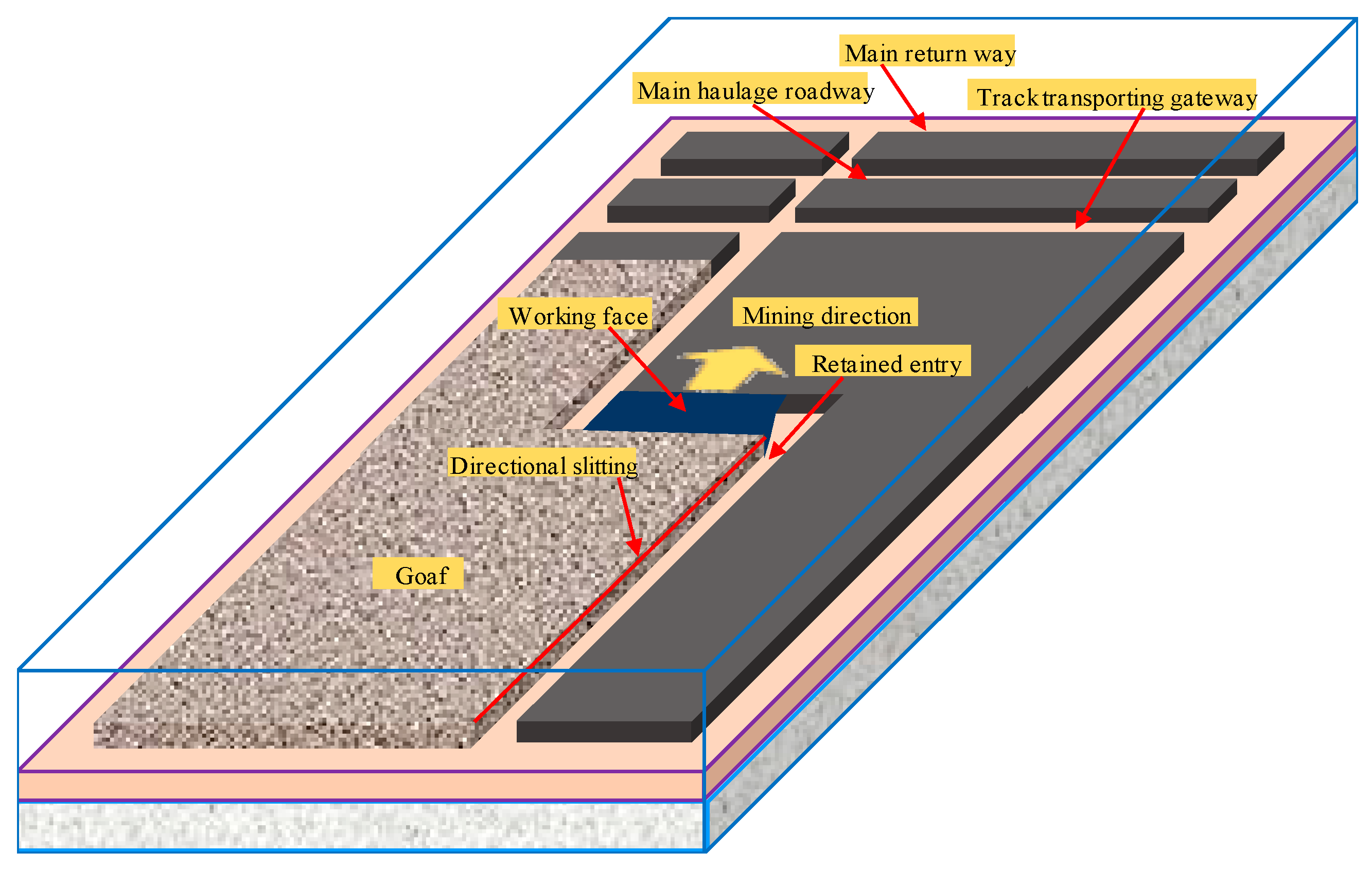
RFANM is a new coal-mining technology. It changed the mining face and roadway layout, process and equipment of conventional coal pillar mining, and gob-side entry retaining significantly [
23]. The coal-mining machine cuts a roadway space beyond the scraper while cutting; then, that is retained for the next mining face using auxiliary technologies, achieving the end of cancelling the roadway driving on the mining face and the coal pillars in the mining face section, which heralds revolutionary significance for the safe and efficient production of coal mines. Its roadway layout is shown in
Figure 1.
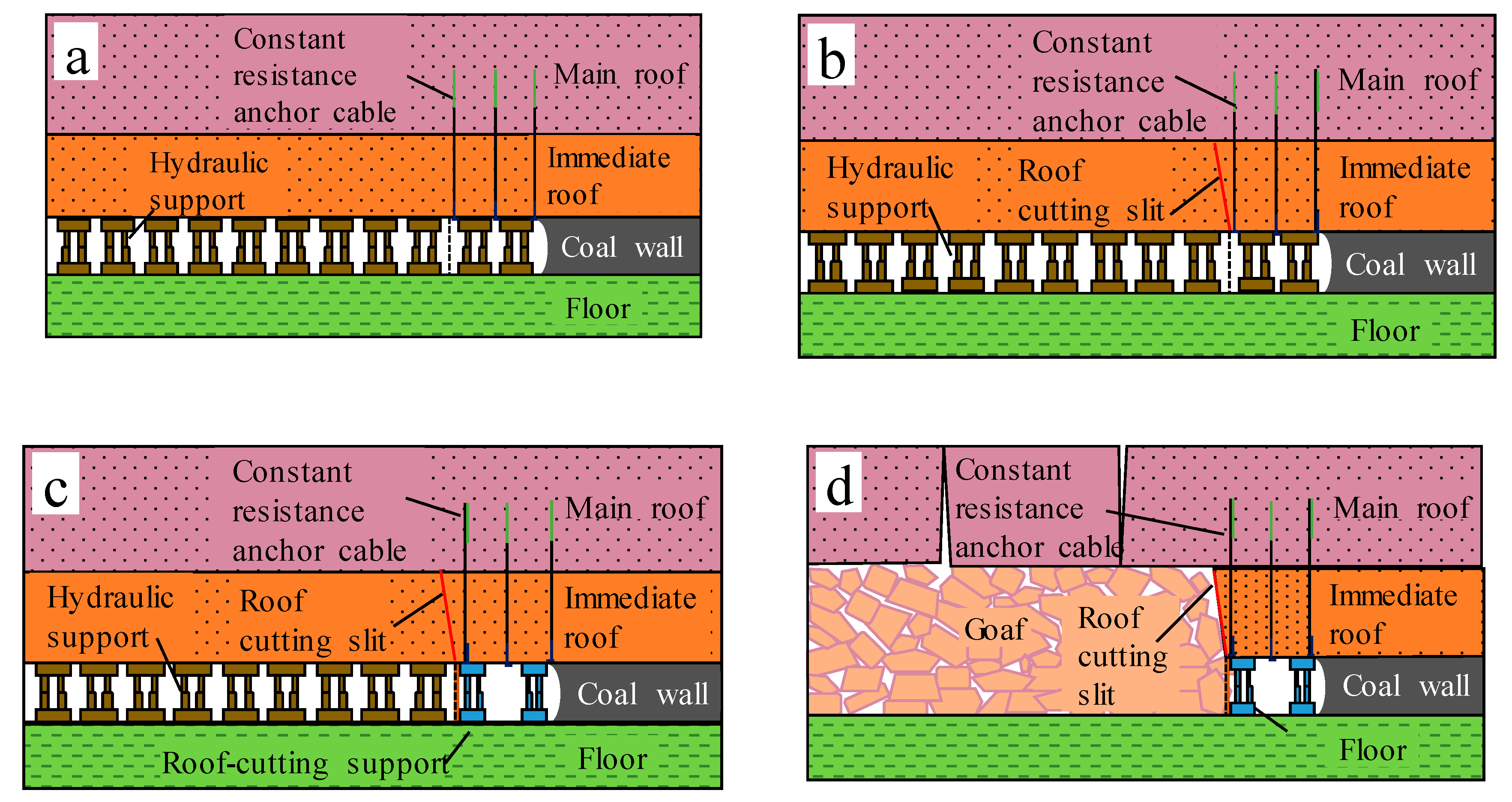
The sections orthogonal to the mining direction shown in
Figure 2 show that the technological process of the RFANM technique can be divided into the following steps: First, in working-face mining, the shearer cuts the coal while leaving the roadway space and forms the arc roadway wall on the side of the coal wall. Then, the roof of retained roadway is supported by constant resistance and large-deformation anchor cable [
24]. In the predefined position above the slit drill, the roof is sliced by the bidirectional, energy-concentrated tension-blasting method, which cuts off the stress transfer between the gob and the roadway roof. The gob roof is automatically caved along the slit face under the action of mine pressure. At the same time, the fallen gangue fills the gob. A gravel gang is formed on the side of the gob under the action of roof-cutting support, U-shaped steel, and other gangue support constructions. Using the RFANM method, non-pillar mining without advancement is successfully implemented.
3. Theoretical Models for Different Fracture Sites on the Main Roof
3.1. Deformation Characteristics of Roof Strata
With the advance of the working face and progressive placement of the hydraulic support accordingly, the roof strata lose their supporting capability, and the immediate roof collapses irregularly, leading to volume expansions, and therefore, filling up of the gob zone [
25,
26]. As the directional cutting is performed on the roadway roof where stress transfers between the roadway roof and the immediate gob roof, and a portion of the main roof was cut off, all rocks in the vicinity of the cutting range would cave down. Roof cutting forces the roadway roof to form a short beam structure, which is considered the “equivalent immediate roof” here.
As the working face continues to advance, when the hanging length of the main roof increases to the limit, the main roof breaks and sinks, resulting in periodic rock pressure appearance [
27]. The gob-side main roof brakes into block A, B, and C, which engage with each other to form the masonry beam structure. Block B revolves and sinks; the end stretching to the gob side was the earliest to contact the gangue, tending to stabilize as the gangue is gradually compacted; therefore, forming a temporarily-balanced rock beam.
After the rock mass forms by the fracture of the main roof stabilizing, a number of rock groups in the overlying strata begin to separate, break, rotate, and cave down. In this stage, the roadway deformation is characterized by parallel subsidence. In the stable section of the roadway which lags behind a certain distance of the working face, the roof-cutting support in the roadway can be retracted and recycled.
3.2. Theoretical Model for Fracture of the Main Roof
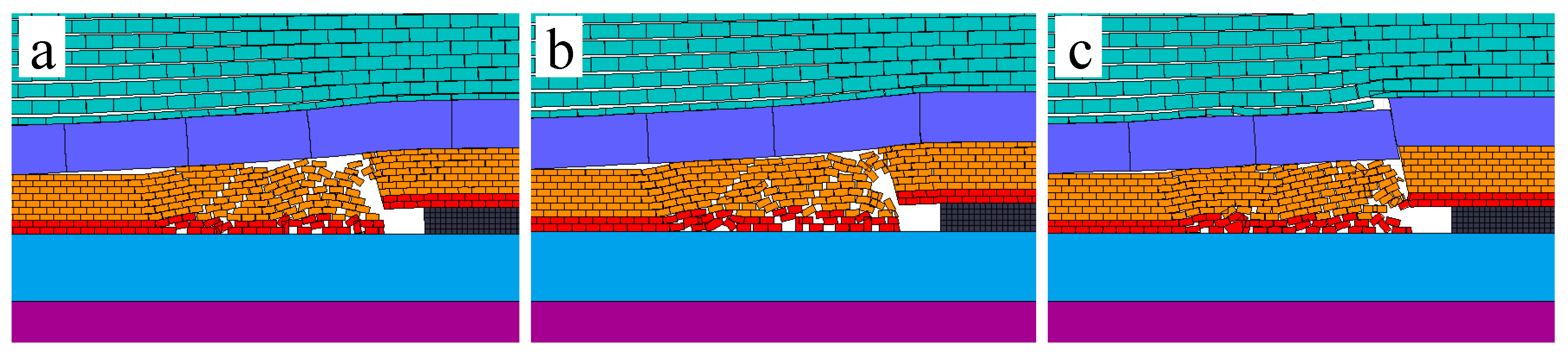
During the roof displacement, the stage of the main roof fracture and the sag is the most intense stage of the roof displacement. Therefore, the theoretical model for fracture of the main roof in RFANM was established with reference to the roof motion in this stage. There are three possible fracture sites for the main roof in RFANM: solid coal side, above the roadway, and gob side.
According to the principle of RFANM and the characteristics of roof motion, the following assumptions of the theoretical model for fracture of the main roof in RFANM were made: (1) The roadway roof rotates and settles around the critical site of the solid, coal-side elastoplastic zone as a rotating axis; (2) the deformation range of key blocks is small, and the weights of strata which cannot form a stable masonry structure above the main roof act uniformly on the key blocks; (3) all roofs in the gob-side cutting range will cave; the supporting force against key blocks is uniformly loaded. (4) Because the angle between the blasting slit angle of the roof and the vertical direction is usually small, the influence of the angle of the slit on the force of the key block is negligible; (5) the curved lane is approximately as a straight lane; (6) the filling effect of gangues is ideal. After the main roof breaks, the rotating angle of block B is approximately zero, so that the horizontal thrust between blocks is negligible. (7) The horizontal shear stress between rock strata is negligible.
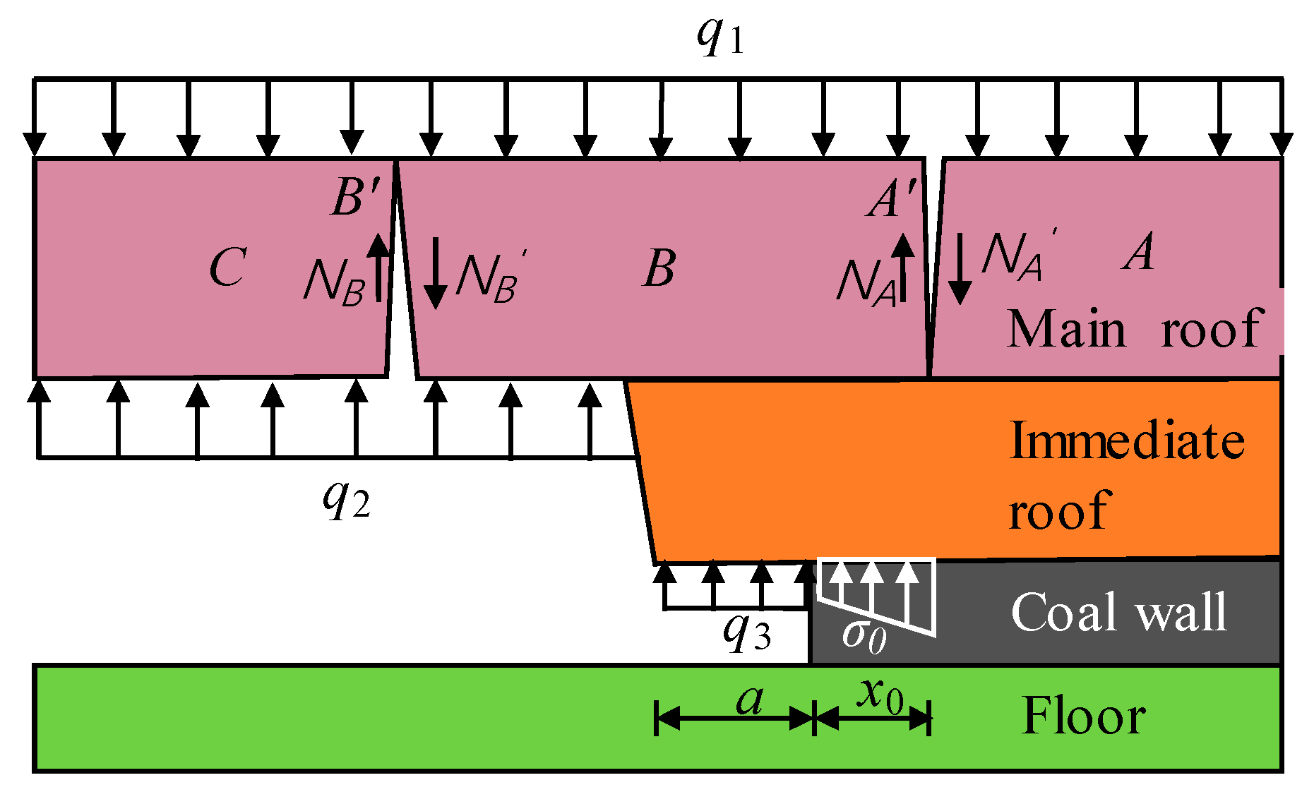
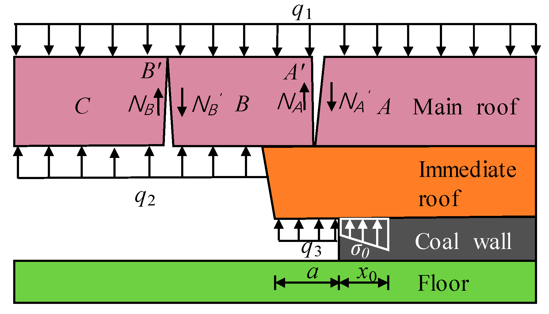
3.2.1. Coal-Side Fracture of the Main Roof
When the strength of temporary support for a roadway is insufficient or the support is provided late, the main roof breaks at the site with a length of
x0 from the solid coal elastoplastic zone of the roadway. One end of the key block B was extended beyond the solid coal side, and the other end was controlled by the gangue support in the gob and temporary support in the roadway. The free-body diagram analysis for the case of fracture of the main roof at the solid coal side was proposed, as shown in
Figure 3.
The equations for the width of the solid, coal-side stress limit equilibrium zone,
x0, and the supporting force of the coal body against the roof,
, [
28] are given by Equation (1):
where A is the thickness of the coal seam in m;
λ is the lateral pressure coefficient;
c, is the interfacial cohesion between the boundary of coal seam and the roof and floor strata in MPa, and
φ is the internal friction angle in deg;
k is the stress concentration factor;
γ is the average bulk density of the overlying strata in kN/m
3;
H is the buried depth of the roadway in m; and
P is solid coal support strength in MPa.
In the process of periodic roof collapse, the roof of a gob is in the state of three-points fixed and one-point free. The equation for the fracture length of key blocks is:
where
S is the length of the mining face and
is the periodic weighting length.
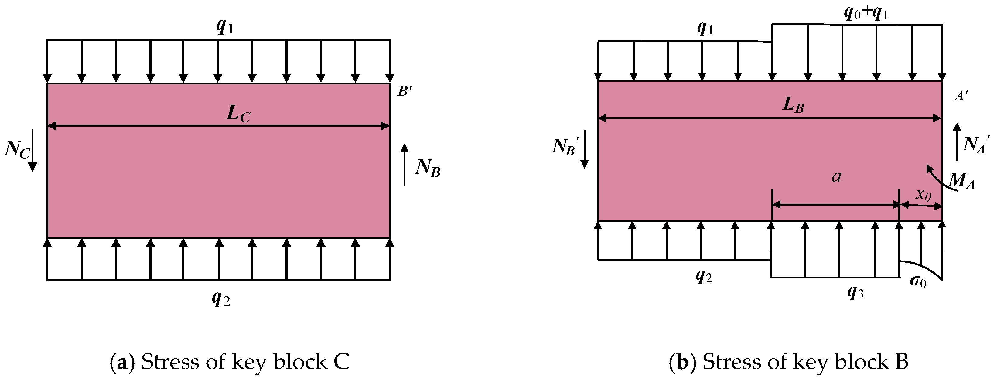
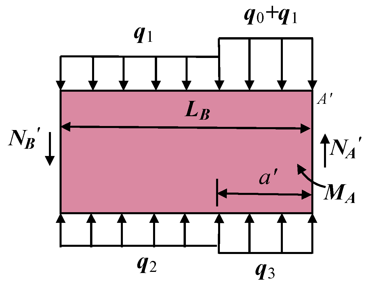
According to
Figure 3, blocks B and C were isolated using a static balance method for stress analysis. The simplified force equilibrium of key blocks is shown in
Figure 4.
is the resultant force in the Y-axis direction of the key block and
in the equilibrium state.
is the total bending moment of key block B at point
A’ and
is the total bending moment of key block C at point
B’.
For block C, as
, we get
Simultaneously with Equations (4) and (5), we get
For block B, as
,
, then
and
where
q0 is the average load of the immediate roof, in kN/m; and
MA is the residual bending moment of key block, in kN·m. And as
P1 =
q3 ×
a, the temporary support strength in the roadway can be obtained by combining Equations (6)–(9).
3.2.2. Fracture Analysis of the Main Roof above the Roadway
When the main roof above the roadway is caved in, so block B is supported by the roadway support body and the gob gangue, the roof motion has the most obvious influence on the roadway deformation. When the crack development of the roadway roof is high or the temporary support in the roadway is provided late, the fracture site of the main roof appears above the roadway. Based on those assumptions, the theoretical calculation model for the fracture above the roadway of the main roof in RFANM was established, as shown in
Figure 5.
The stress analysis of blocks B and C was performed using the static balance method. The stress on block C was the same as that under the gob-side fracture condition. Free body diagram of block B is presented in
Figure 6.
As
, then
where
is the distance from the fracture site of the roof to the edge of the gob-side roadway, in m. Simultaneously with Equations (6), (7), and (11), the temporary support strength in the roadway can be obtained.
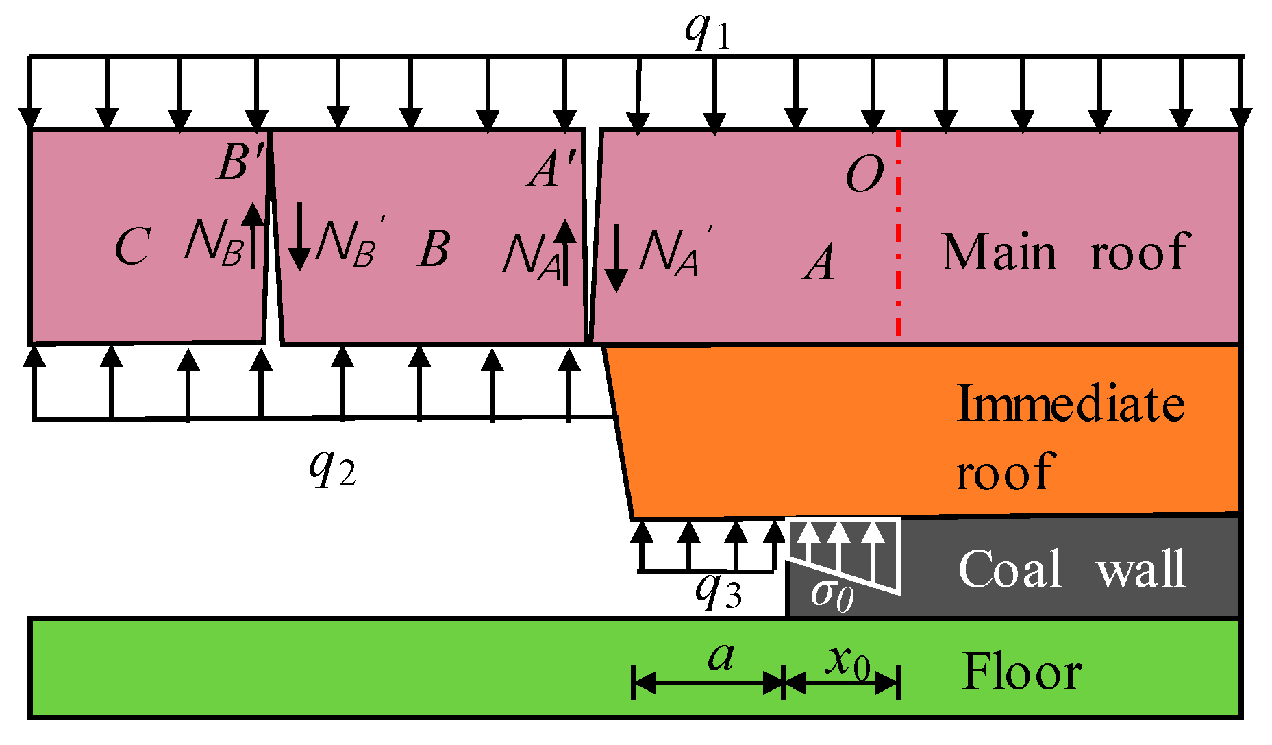
3.2.3. Fracture Analysis of the Main Roof at the Gob Side
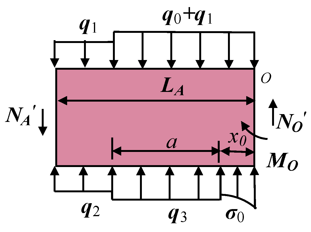
When the theoretical properties of the equivalent immediate roof manifest sufficient stand-up time or the temporary support strength in the roadway was large, the main roof broke along the slotting line. Under this fracture circumstance, key block B was stabilized with the gangue support. The length of the cantilever length above the roadway was less. The stability of the roadway formed was provided by the supporting force of solid coal and the support in the roadway. The theoretical model for the main roof fractures at the gob side was obtained, as shown in
Figure 7. The simplified force equilibrium of key blocks A is shown in
Figure 8.
For block B, as
,
,
Simultaneously with the above equations, use:
Simultaneously with Equations (15) and (16), solve the temporary support strength in the roadway as:
For convenience of simplification, we assume LA = LB; then is obtained. Meanwhile, the residual bending moment of the beam fracture, MA, is much less than the bending moment occurring in the main roof, MO. By comparing the theoretical models for the fracture of the main roof at the gob side and at the solid coal side and Equations (10) and (17), obviously, the temporary support strength in the roadway when the fracture site of the main roof is at the solid coal side is greater than that required at the gob side; namely P1 > P3. The fracture occurrs above the roadway; one end of block B is on the roadway, and there is no supporting force of the solid coal. Furthermore, comparing Equations (10) and (12), we know that the temporary support strength in the roadway when the fracture site of the main roof is at the coal side is greater than that required above the roadway; namely P1 < P2. Therefore, it was concluded that when the temporary support residence in the roadway P > P2, the fracture site of the main roof outside the roadway is at the gob side or the solid coal side; when P < P2, the fracture of the main roof above the roadway leads to failure.
5. Engineering Applications
5.1. Formatting of Mathematical Components
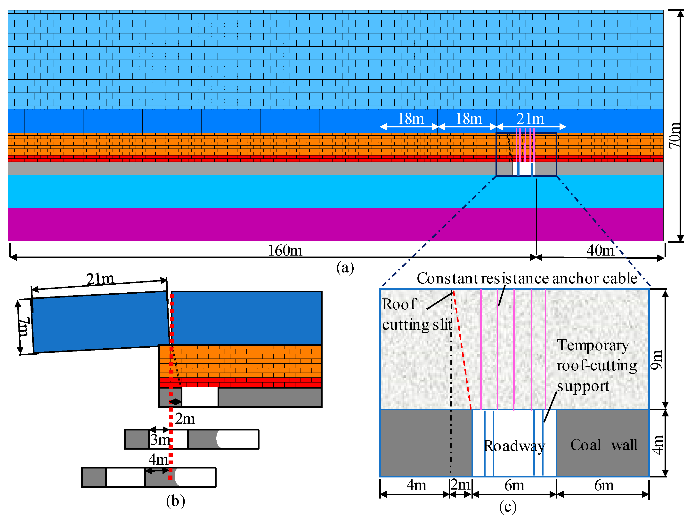
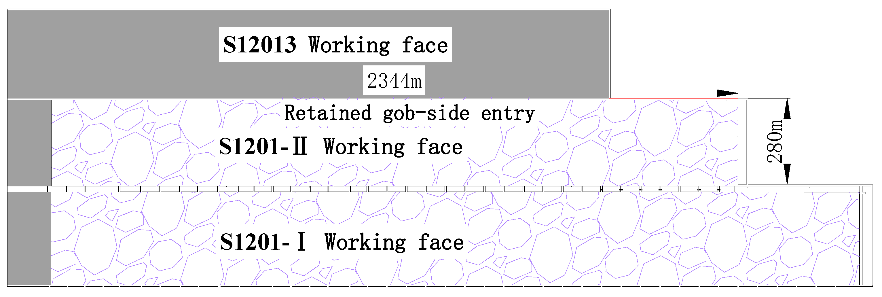
The coal seam extracted on the test face was the middle section of Yanan Formation of Jurassic Series. The coal seam thickness was 3.81–4.35 m, the average thickness was 4.11 m, and the buried depth was 115–170 m. The occurrence of the coal seam was stable and its dig angle was approximately horizontal. The dip length and strike length of the working face were 280 and 2344 m, respectively. The position and the layout of the S1201-II working face are shown in
Figure 13.
The main roof of the mining face was medium-grained sandstone with a thickness of 5.4–21.5 m, a medium sorting behavior, and large cross-bedding. The immediate roof was siltstone with a thickness of 0.78–4.05 m. The immediate floor was siltstone with a thickness of 1.8–16.3 m, sandwiched and interbedded with a thin layer of fine-grained sandstone; the cleavage is shown. The main roof was fine-grained sandstone with a thickness of 3.2–19.6 m and wavy bedding.
5.2. Roof Control and Roadway Formation Effect
Generally, the probability that the main roof breaks above the roadway is smaller than those for the solid coal side and the gob side, but its threat to the roadway stability is often the highest. During the overburdening strata movement, the temporary support in the roadway should not only provide a large supporting force to resist the deformation, but also functions as “yielding” to deal with the “given deformation” of the main roof. Cutting roof support is the main temporary support for the roadway. The support strength of roof-cutting support has an important influence on the fracture position on a basic roof and plays an important role in roadway stability.
RFANM follows the mining face closely to provide active support against the roadway roof with constant resistance and a large deformation anchor cable. The constant-resistance anchor cable is mounted before the surrounding rock of the roadway becomes deformed, so as to avoid the bed separation from the roadway roof. The support provided by the constant-resistance anchor cable enhances the anti-breaking capacity of the equivalent immediate roof, so that the fracture site of the lower roof tends to approach the gob side, which is beneficial to avoid the fracture of the main roof above the roadway.
By designing the slotting parameters, the gangues in the gob can achieve better effects of cracking-expansion and filling, which alleviate the impact of the intense motion of key blocks on the stability of the surrounding rock. Subject to the supporting force of the gangues in the gob and the temporary support in the roadway, the fracture line of the main roof shifts to the depth of the solid coal side or to the gob. This is significant for the stabilization of the surrounding rock of the roadway.
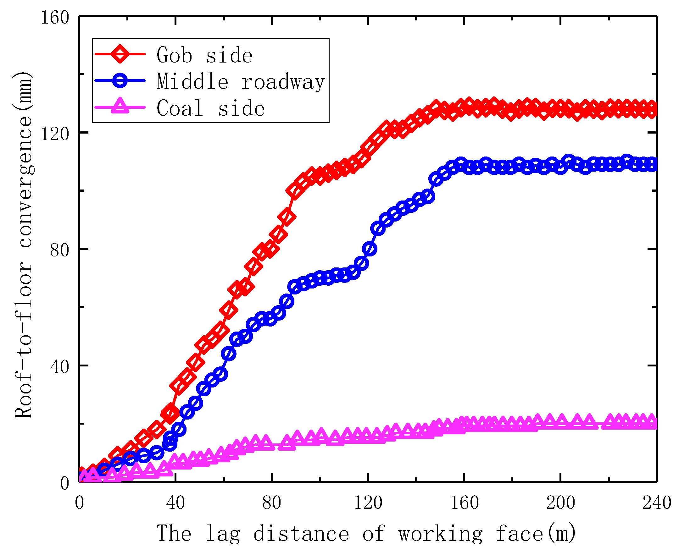
The variation curve of the roof and floor displacement with the advance of the mining face, as shown in
Figure 14, was drawn by monitoring the roof displacement and selecting the typical measurement points with timely distribution and the longest monitoring duration at 930 m from the open-off cut. The variation of the roof and floor displacement was similar to that of the fracture of the main roof at the solid coal side and the gob side. The maximum roof and floor displacement at the gob side was 128.1 mm, which was approximately equal to the maximum deformation at the solid coal side. It was initially concluded that the main roof in the formation section broke at the solid coal side.
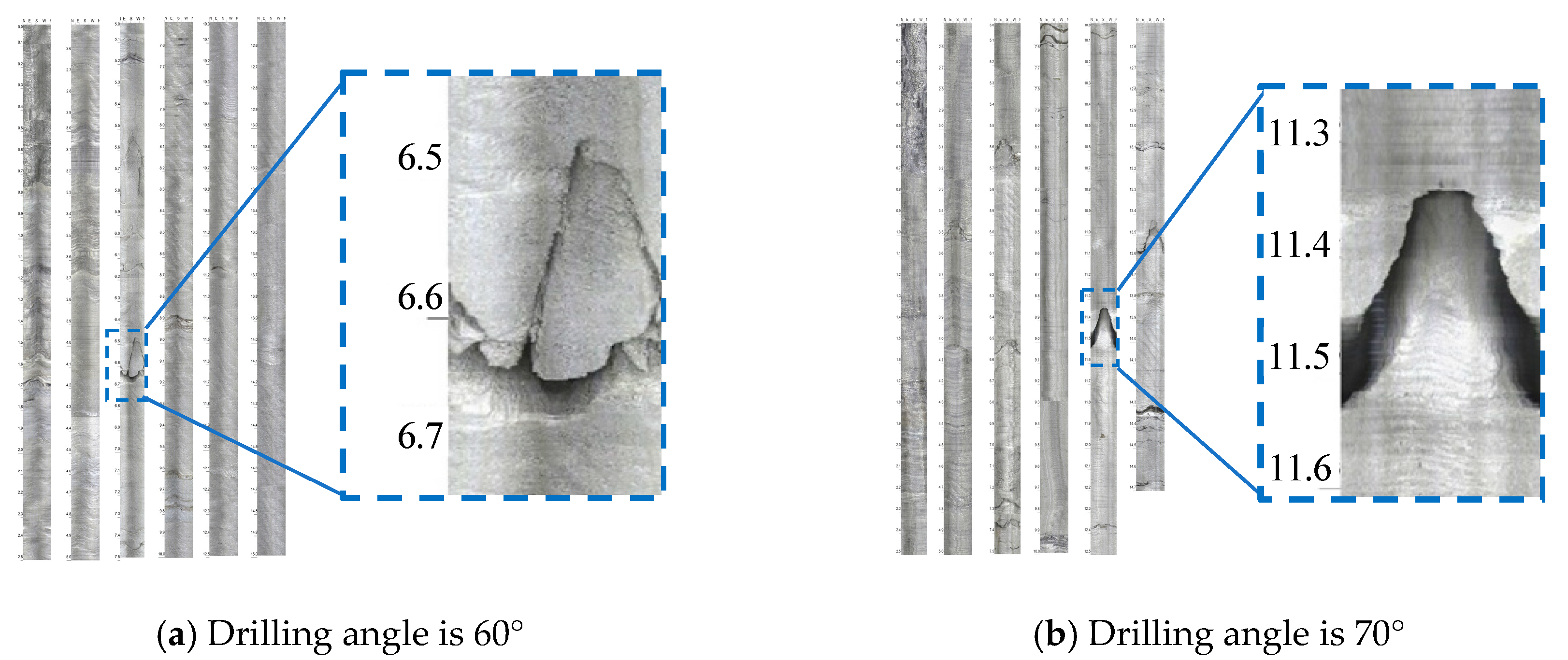
The roadway roof was drilled and peeped using a mine borescope.
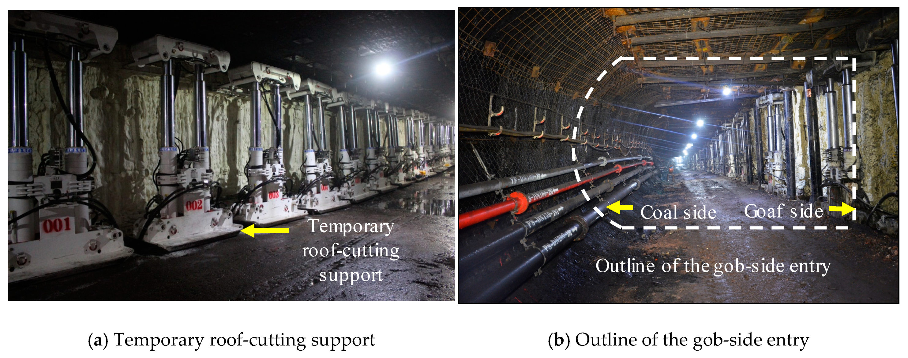
Figure 15 shows the peeping result at 930 m from the open-off cut and 10 cm from the coal wall with the drilling angles of 60° and 70°, respectively. It was observed that the peeping result of the fracture site of the main roof in this entry retaining section 3.6 m from the coal wall was basically consistent with the field displacement monitoring and simulation result. The field roadway formation effect is shown in
Figure 16.
6. Conclusions
In this study, the theoretical models for different fracture sites of the main roof were established, the equations for temporary support strength in the roadway when the main roof was at three fracture sites were derived, respectively, the critical value for the temporary support strength in the roadway was thus obtained, which offered theoretical evidence for the support design in RFANM.
We discovered that the fracture observed in the main roof at different sites was closely related to the stability of the surrounding rock of the roadway. The required temporary support in the roadway varied from site to site. When the main roof broke above the roadway, the temporary support strength required for the roadway to maintain stability was the largest. Thus, during the mining working in RFANM, the main roof was prevented from breaking above the roadway.
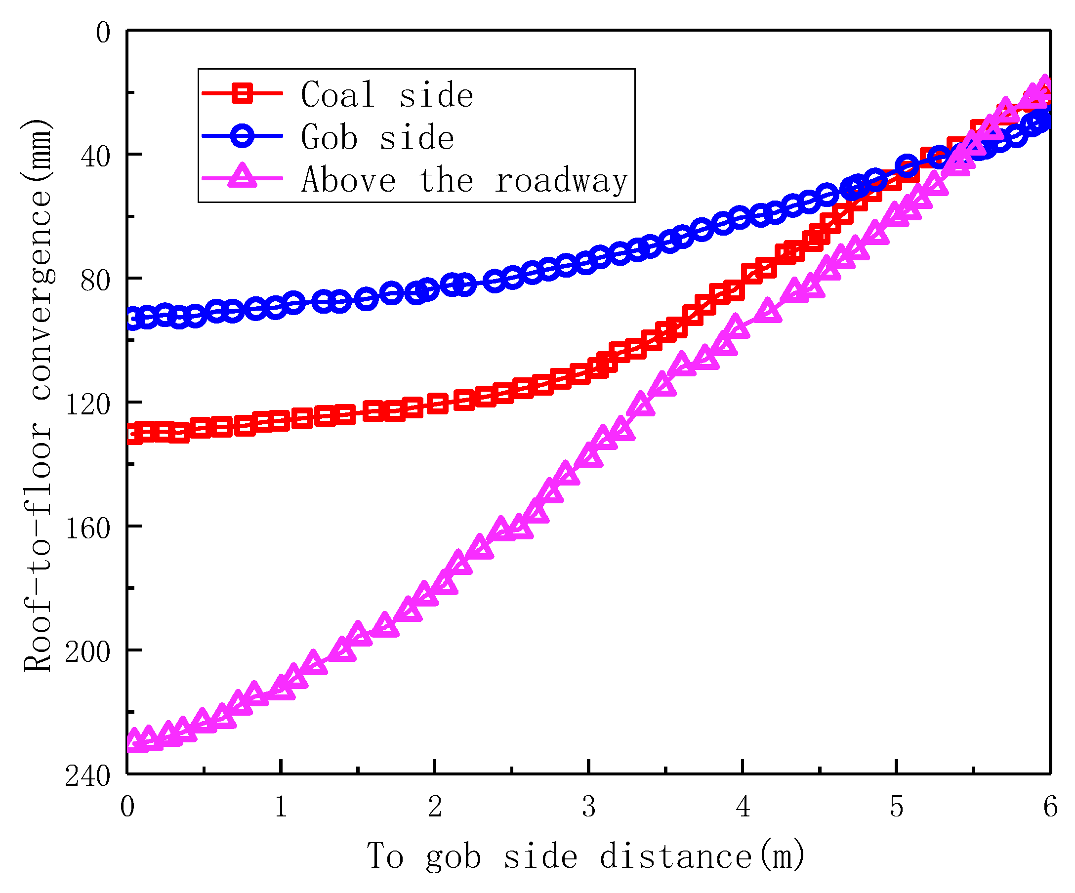
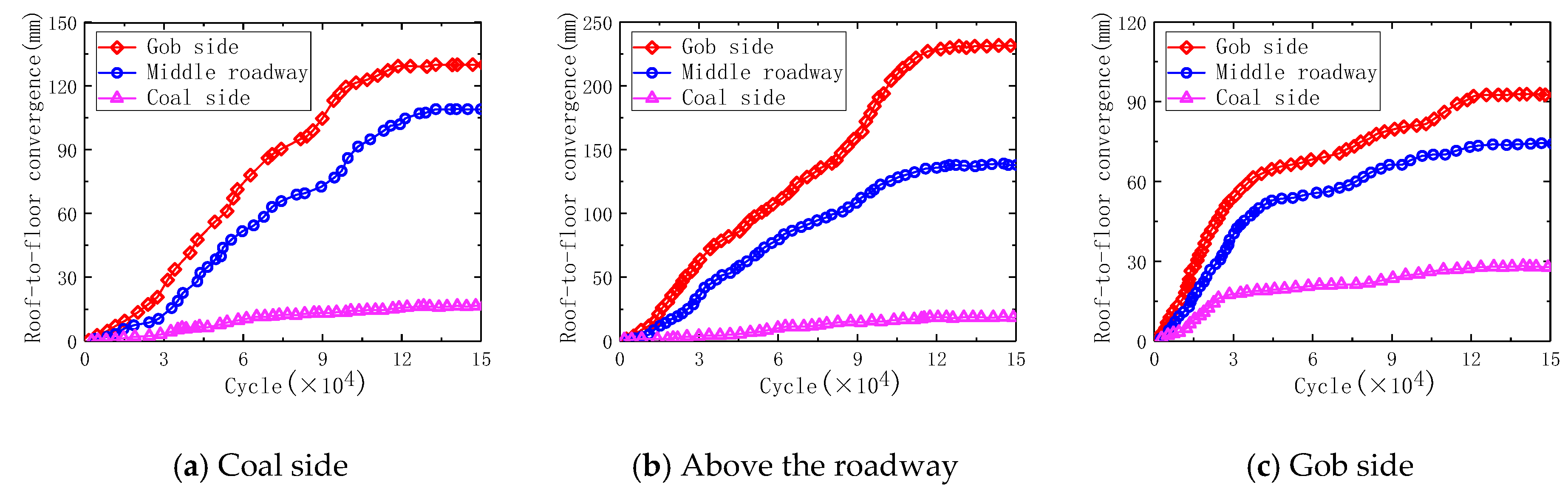
The deformation of key blocks at three fracture sites were simulated using the UDEC. The comparison of displacement variation of the roadway roof indicates that the roadway deformation is smaller when the main roof fractures at the solid coal side and the gob side.
The industrial test for RFANM was conducted on the S1201-Ⅱmining face, deformation of the roadway can be effectively controlled by using roof cutting support, constant resistance anchor cable support, resulting in good formation effect, better social and economic benefits.

 ,
, 


