Article

Ventilation as an Indispensable Tool for Healthy Constructions: Comparison of Alicante’s Urban Railway Tunnels

by
Carlos Rizo-Maestre
*,
Víctor Echarri-Iribarren
and
Antonio Galiano-Garrigós
Department of Architectural Constructions, University of Alicante, Ctra. San Vicente Del Raspeig S/N, 03690 San Vicente Del Raspeig (Alicante), Spain
*
Author to whom correspondence should be addressed.
Sustainability 2019, 11(22), 6205; https://doi.org/10.3390/su11226205
Submission received: 2 July 2019 / Revised: 23 September 2019 / Accepted: 24 September 2019 / Published: 6 November 2019
(This article belongs to the Section Tourism, Culture, and Heritage)

Abstract

:
The majority of scientific agencies in the field of medicine and health, including the World Health Organization, consider radon gas a very harmful element for humans. This element, in its gaseous state, is radioactive and is present in almost all land in which buildings are implanted, especially in granitic soils, which present higher levels of radon gas. Nongranitic soils have traditionally been considered to have low radon levels. In addition to the contributions made by this article, it is very relevant that there are many countries, including Spain, in which the technical codes for their construction regulations do not include the maximum radon dose that a building can hold so that it is not harmful to humans nor do they hold the measures necessary to remedy excessive accumulation. The main objective of this research is to demonstrate the need for ventilation in buried works. To do this, a comparison is made between two railway tunnels in the urban fabric of the city of Alicante: one of them is in operation (Benacantil Mount) and the other is in the excavation phase (Serra Grossa). When underground railway installations are planned, they are equipped with large air ventilation systems due to the pollutants generated by ground exposure. These mechanical systems consist of suction turbines that expel the air to the outside. Research shows that radon gas is an indicator of an area’s air quality. In addition, ventilation in railway tunnels (mechanical and natural) allows for air renewal and improves the air quality.

1. Introduction

The main objective of this research is to demonstrate the need for ventilation in underground infrastructure. To do this, a comparison is made between two railway tunnels in the urban fabric of the city of Alicante: one of them is in operation (Benacantil Mount) and the other is in state of excavation (Serra Grossa).
When underground railway installations are planned, they are equipped with large air ventilation systems due to the pollutants generated by ground exposure. These mechanical systems consist of suction turbines that expel the air to the outside.
The two tunnels chosen for the comparison are located in the two most important mountains of the city of Alicante: Benacantil Mount and Serra Grossa, joined at their base and coastal to the Mediterranean Sea. The Benacantil Mount facility is in operation, whereas the Serra Grossa facility is in the construction completion phase and will be inaugurated in 2019 (Figure 1).
This comparison hypothesizes that there is a need to improve ventilation so as to achieve better indoor air quality in underground buildings, using radon gas as an indicator. Specifically, the accumulation of radon in both constructions will serve as an element to test the air renewal, since the presence of radon gas is directly related to the ventilation [1,2].

2. Indoor Air Quality and Health

The indoor air quality of a site depends to a certain extent on outdoor air pollution and other building conditions [3]. This coexistence of people in unhealthy stays can have significant and detrimental effects. Inside buildings, in addition to the characteristics of the buildings (materials, ventilation, place, etc.) there are other elements that pollute the air such as the coexistence of people (emit CO2), volatile organic compounds (VOCs) present in the environment or biological pollutants themselves (germs, viruses, and bacteria) [4,5]. These elements can develop serious problems for people and in their worst version, cancer. It has been demonstrated that greater coexistence in contaminated spaces increases the risk of contracting a disease [6].
Radon is a chemical element, whose symbol is Rn and atomic number is 86. It descends mainly from Uranium-238, Thorium-232, and Uranium-235. Uranium and Thorium are found in low concentrations in soil, rocks, and water [7]. The concentration of Thorium in the earth’s crust is between three and four times that of Uranium, although it is not evenly distributed. The concentration rates of these elements and their chain of descendants vary from place to place [8]. The accumulation of radon therefore varies and depends on the rate of matter containing Uranium and Thorium and parameters such as humidity, porosity, or air renewal [9]. Other parameters influencing radon concentration in the atmosphere are wind speed, rainfall and atmospheric pressure [10].
Radon has been considered carcinogenic by the World Health Organization (WHO) since 1998, according to the International Agency for Research on Cancer (IARC) and the U.S. Environmental Protection Agency (EPA), which classify it as Group 1 and Group A carcinogen, respectively. The main adverse effect of inhaling radon and its breakdown products is the risk of lung cancer [11].
Radon, like gas, is not significantly retained in the respiratory tract. However, 90% of their descendants may be attached to aerosol particles present in the air, which, depending on their size, may be retained at different levels of the respiratory system. The smallest, the respirable fraction, will reach the most sensitive areas of bronchial and pulmonary tissue, depositing there, along with the remaining 10% of the disintegration products. The deposition of these particles generates a source of emission of particles α high density, so that a part of this tissue receives a high exposure, increasing the possibility of developing a carcinogenic process. The dose received in the lung by beta radiation ( β ) or gamma radiation ( γ ) is negligible compared to that due to alpha particles ( α ) [12].
In the absence of sufficient data, estimates of the risk associated with domestic exposure to radon were initially based on extrapolation of the results obtained for miners [13]. This extrapolation had a number of limitations, among which the following stand out.
  • The absence of data concerning women and children who obviously did not work in the mines.
  • Uncertainties in the health effect of the dose rate.
  • Lack of data on smoking habits in most studies.
  • Inadequate control of other confusing variables (such as exposure to gamma radiation or suspended aerosols).

2.1. Importance of Ventilation in the Construction Phase of Tunnels

Two stages in prevention of tunnels must be distinguished; the first, much more restrictive, is tunnel drilling, where the maximum safety protocols are applied at the different action levels (gases in each tunnel advance generated by the terrain and/or the machinery used in the excavation), and the second once the work has been completed and put into operation. This study addresses the two stages since one of the tunnels is in operation (Benacantil Mount) and the other in the work phase (Serra Grossa).
In 1990, the European Atomic Energy Community (EURATOM) published for the first time Recommendation 90/143, “On the protection of the general public against the dangers of exposure to radon indoors” [14]. The addressees of this study are the Member States which are recommended to follow a series of recommendations for limiting indoor radon exposures. These include applicable regulations and standards for the design of both realised and future buildings.

2.2. Radon Gas As an Indicator of Ventilation
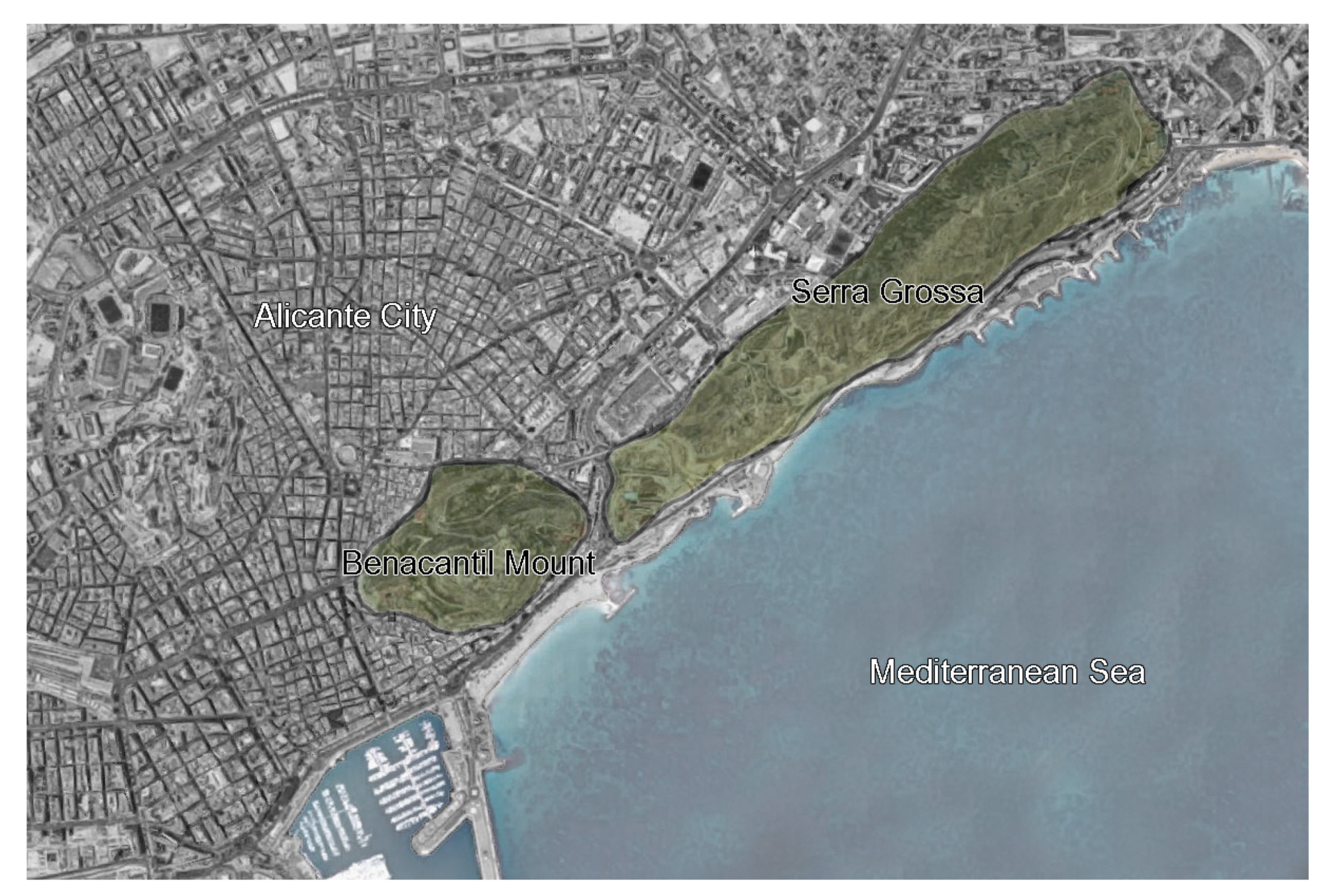
Radon is a chemical element belonging to the noble gases group. It is found mainly in the subsoil. Uranium in the soil decays and produces radium, which remains in the soil. When this decays, it emanates to the surface in the form of a gas [15]. In its gaseous form it is colorless, odorless, and tasteless, and therefore undetectable [16].
Three-quarters of the radioactivity in the environment comes from natural elements [17], and radon is the major source of this natural radioactivity [18]. The public health problems generated by its concentration both inside buildings and in drinking water means that it must be considered for evaluation [19].
Radon gas is produced as a result of the decay of the uranium contained in rocks [20]. Radon emanates from the ground and is concentrated mostly in enclosed spaces [21], so it is highly recommended that homes and workplaces are properly ventilated [22].
Radon disintegrates due to so-called ionizing radiation, because when it enters matter, it usually pulls electrons out of the surrounding atoms via a process known as ionization [23]. If the matter is biological tissue with a high water content, the ionization of the water molecules can give rise to so-called free radicals, which have a high chemical activity [24] that can alter important molecules that form part of the tissues of living beings [25]. These alterations may include chemical changes in DNA, the basic organic molecule that forms part of the cells that make up our body [26]. These changes may lead to the appearance of biological effects, including abnormal cell development [27]. These alterations may be more or less severe, depending on the dose of radiation received [28]. The main effect of the presence of radon in the human environment is the risk of lung cancer [29]. This radioactive gaseous element is present in almost all construction materials and in the land on which buildings are installed [30].
Different radon measuring devices are available. Some are active, requiring electricity and allowing for a continuous recording of the radon gas concentration and fluctuations during the measurement period [31]. Others are passive and do not require an electrical current to operate in the sampling environment [32].
“Ionic Chambers of Electrets” (CIEs) have been used to conduct this research. CIEs are passive devices that function as integrating detectors to measure the average concentration of radon gas during the measurement period. The electret functions both as an electric field generator and as a sensor in the ionic chamber. The radon gas enters the chamber via diffusion through an inlet equipped with a filter without allowing the rest of the elements produced during the disintegration process to pass through [33]. The radiation emitted by radon and its disintegrating products formed inside the chamber ionizes the air inside the chamber, thereby reducing the detector surface voltage [34]. Subsequently, a calibration factor relates this voltage drop to the radon concentration existing in the space and time studied [35].
The most important source of radon in isolated buildings or ground floors is the radium present in the ground. The radium concentration in the soil is generally between 10 and 50 Bq/kg, although it can reach much higher values. The average value is approximately 40 Bq/kg. The amount of radon entering an interior from the soil depends mainly on the concentration of radium-226 in the subsoil and the permeability of the subsoil.
Predictive maps of radon content are available in most countries, mostly from the igneous compositions of the terrain [36]. For example, Sweden has developed maps based on the measurement of the geogenic potential of radon, which indicates the level of risk by area and is estimated from the concentration of radon in the ground at a depth of 1 m [37,38]. Likewise, the usefulness of methods based on other variables, such as the concentration of radium-226 in the soil or the equivalent of uranium (eU), has been proven. In the case of France, for example, the national map has been drawn on the basis of geological maps and the average uranium content of each geological unit [39]. The German map [40] has also been creating using the geogenic potential of radon, as has the Czech map [41]. All radon gas predictive maps consider granitic soils to be the highest risk in terms of concentrations [42], considering clay soils as having a low presence of radon gas. As of February 2018, the Technical Building Code (CTE) of Spain does not yet contemplate the maximum dose of Radon that can be housed in one building, or how to contain it [43].
The Spanish Mediterranean coast, where the city of Alicante is located, is mainly clay [44]. In the urban center of the city are the two mountains compared in the study: Benacantil Mount and Serra Grossa. Therefore, they can be considered to have the same igneous composition [45,46].
The interior ventilation of the buildings is essential to define their air quality because the more renovations there are per minute, the fewer foul particles there are in the environment. Therefore, radon gas is used to analyze whether the ventilation is adequate inside railway tunnels, i.e., whether the area where the extraction machines are located (Benacantil Mount) has better ventilation than the area where it is excavated in the rough (Serra Grossa).

3. Measuring Zones

The two tunnels analyzed in the study are located in the two coastal mountains in the city of Alicante: Benacantil Mount and Serra Grossa (Figure 2). The Serra Grossa tunnel in Alicante has similarities with the Benacantil Mount, as both are civil works that respect the slopes of the mountains and have been recently designed. The Serra Grossa tunnel is at a standstill, but the excavation and reinforcement work have been almost entirely conducted, except for the northern emboquille.
The measuring equipment was tested during the working phase to check its correct operation. In the construction stage of the tunnel, the radon gas control element is included in the ventilation section of the underground excavation works. Working with tunnel boring machines raises harmful particles for the workers, and they have to be expelled from the workers’ place of work with mechanical air extraction elements.

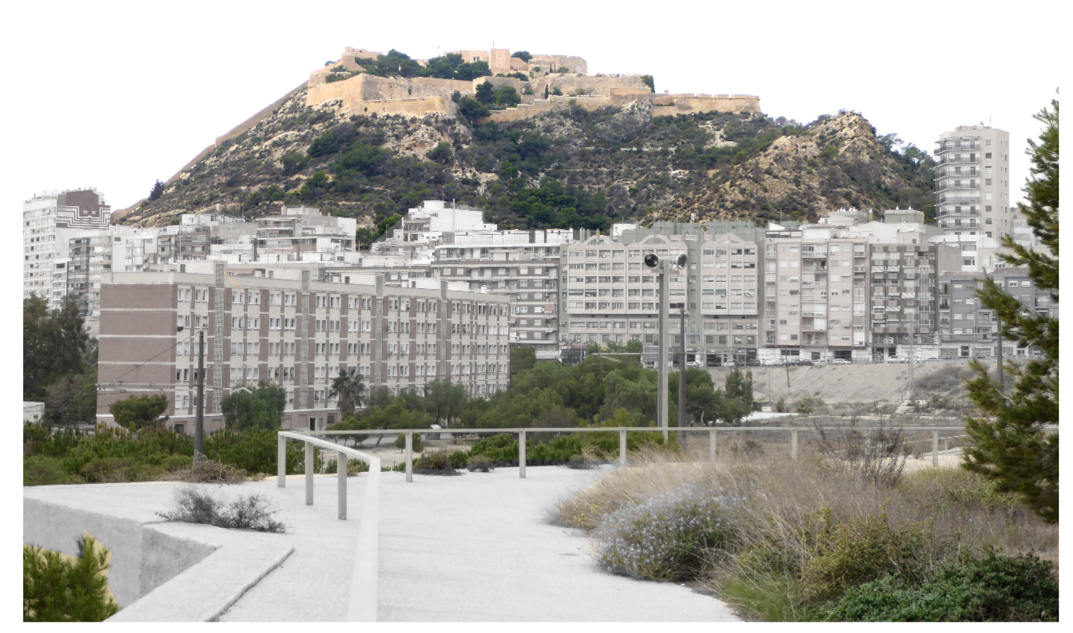
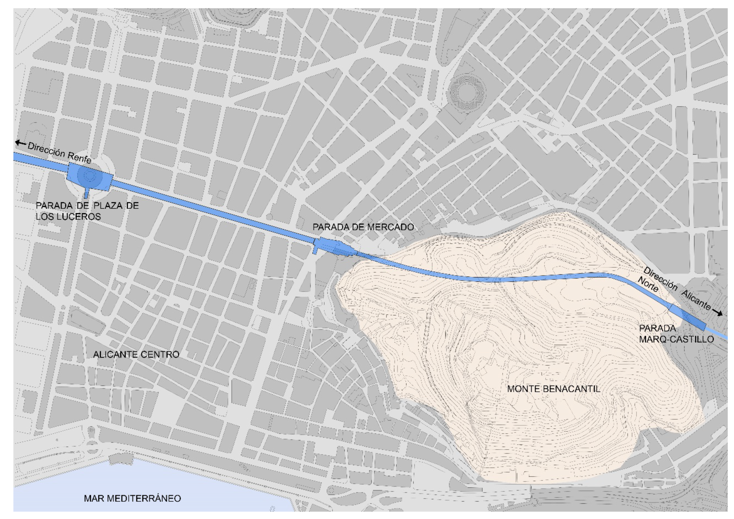
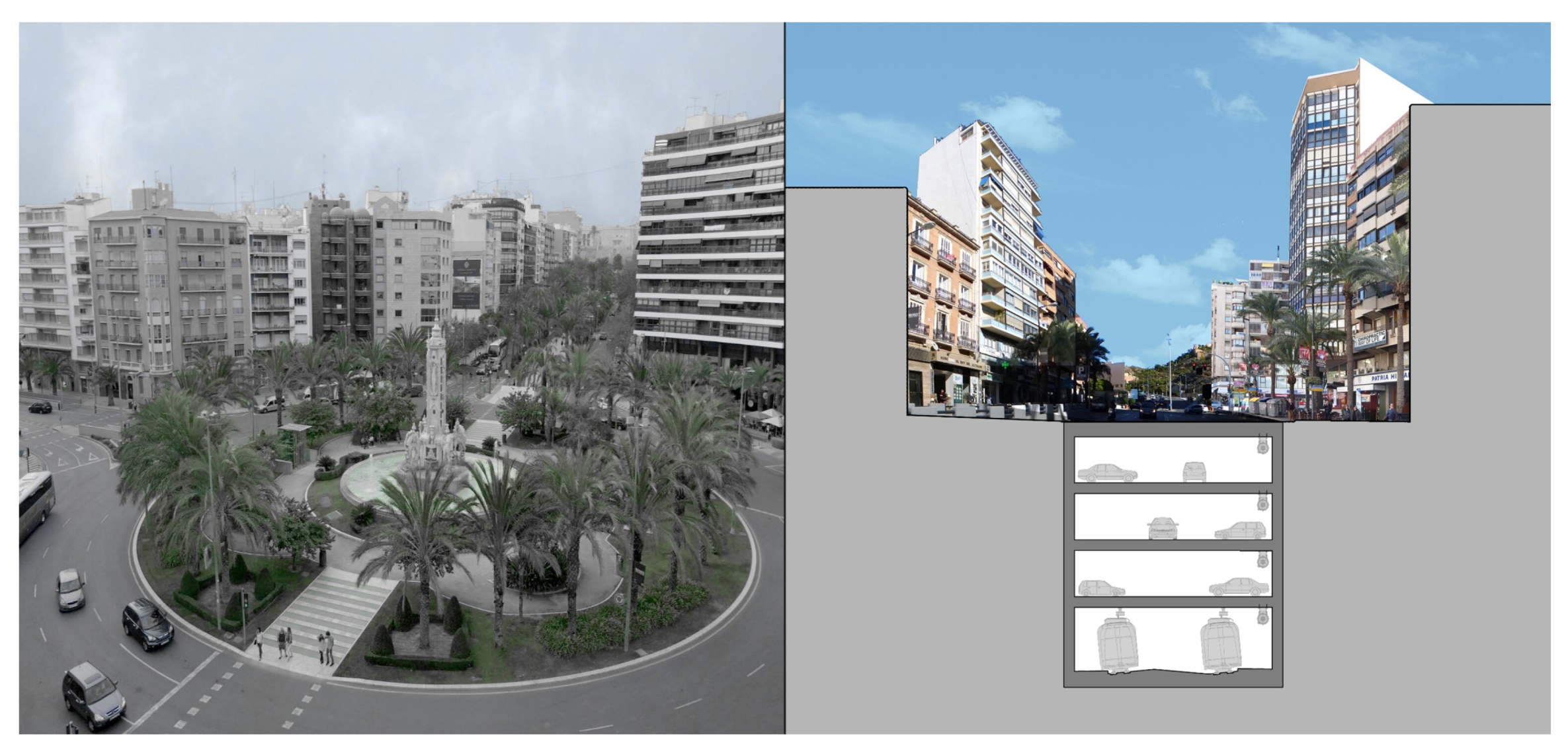
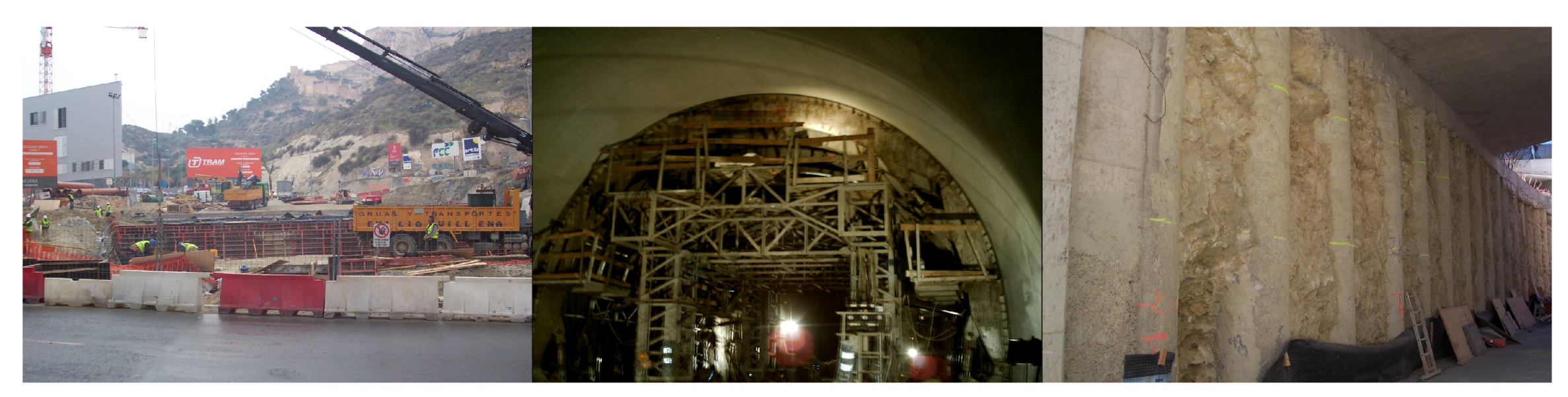
3.1. The Benacantil Mount Railway Tunnel

Benacantil Mount, due to its position, is the highest point in the center of Alicante. It is located in a privileged area due to its proximity to the sea and has an approximate height of 166 m where the Castle of Santa Bárbara is located [47,48], this being the highest construction object in the town center (Figure 3). This fortification, for its height and great view of the panorama, is the most important historical construction object in the city, which served as a defense in medieval times. At its origin, this construction was surrounded by a wall for the protection of its inhabitants, which has changed over the years due to the different armies that have controlled the fortification. On the south side of the castle is the Polvorín de la Ereta [49], a building used for guarding the weapons and ammunition of the city’s army.
The Benacantil Mount railway tunnel is, together with the Serra Grossa tunnel, one of the most important civil works conducted in the 21st century in the city of Alicante. This infrastructure connects the Marq–Castillo stations, at the foot of Benacantil Mount with the Luceros Station, although in the future its pretensions plan to reach the Renfe Railway Station itself and serves as a connection to the city with travelers arriving from all over Spain. The route of the tunnel passes under Alfonso X el Sabio Avenue and Station and Jaime II Avenues until it enters Benacantil Mount (Figure 4), reaching a point fifteen meters below the street’s zero level.
The planning of the Alicante Metropolitan Transport (TRAM) is part of the Strategic Infrastructure Plan 2004–2010, with the aim of improving the city’s mobility system. Alicante has a history with trains, since although the TRAM disappeared thirty years ago, it kept the “trenet”, a train that connected the entire north coast of Alicante with the center.
The tunnel began as one of the initiatives of the Valencian Community in the field of transport on 10 November 1986, when the public law entity Ferrocarrils de la Generalitat Valenciana, dependent on the Consellería de Obras Públicas, Urbanismo y Trasporte, was created with the intention of developing suburban trains and metropolitan railway. In 1988, the subway was inaugurated in Valencia and four years later the TRAM began its development in Alicante.
The railway infrastructure that, in the future, will connect the Renfe station with the northern area of Alicante had the problem of passing through one of the most important avenues (Alfonso X el Sabio), where road traffic is very dense in the heart of the city center. The project eventually proposed the idea of burying the tunnel and providing the city with parking on these large avenues, as shown in the photomontage of Figure 5.
Based on the idea of burying the tunnel and marking the areas where the train passes through, in July 2005, the Department of Infrastructures and Transport commissioned Alicante architect Javier García Solera to design the new underground TRAM station at Luceros Place, which would link the road route from the Castle of Santa Bárbara stop to the city center through a tunnel [50]. This station is located below the square from which it takes its name. It is between the market stations and the future Renfe station, which will be an intermodal of the city, housing both the metropolitan train and the long-distance train.
The Luceros station is located in the center of the square and located 22 m under the ground floor. The entrance to the TRAM stop is on level −1, which can be reached from a staircase or an elevator. This was the only element that changed the street level elevation. The train passes at level −4 and adapts to the slopes of the street until it enters the slopes of Benacantil Mount. Levels −2 and −3 correspond to a car park serving the Alfonso X el Sabio and Jaume II avenues and is only interrupted at the TRAM Luceros and Mercado stops.
The tunnel that connects the northern part of Alicante from the skirts of the castle to the future Renfe stop is one of the most important civil works that has been performed in Alicante in recent years. To enact this project, several teams took part, connecting these two relevant points of the city and providing underground parking, respecting the avenues of Alfonso X el Sabio avenue, the station and Jaume II avenue, through which the tunnel passes.
The system used to perform this engineering work had many elements (Figure 6); to excavate Benacantil Mount while respecting the slopes, tunnel boring machines were used up to the areas where other construction techniques could be used. The excavation processes were conducted in sections or bataches between 5 and 10 m, which allowed the areas to be drilled and the sides to be reinforced with large reinforced concrete walls made in crude to finish the interior of the tunnel later on.
In the great avenues of Alfonso X el Sabio, the Station and Jaume II, the tunnel construction process contemplated taking advantage of the space between the street and the tracks to create a car park. Therefore, a pile system was used that consisted of introducing the large elements of reinforced concrete by means of drilling machines, which previously reinforced the walls before the excavation.

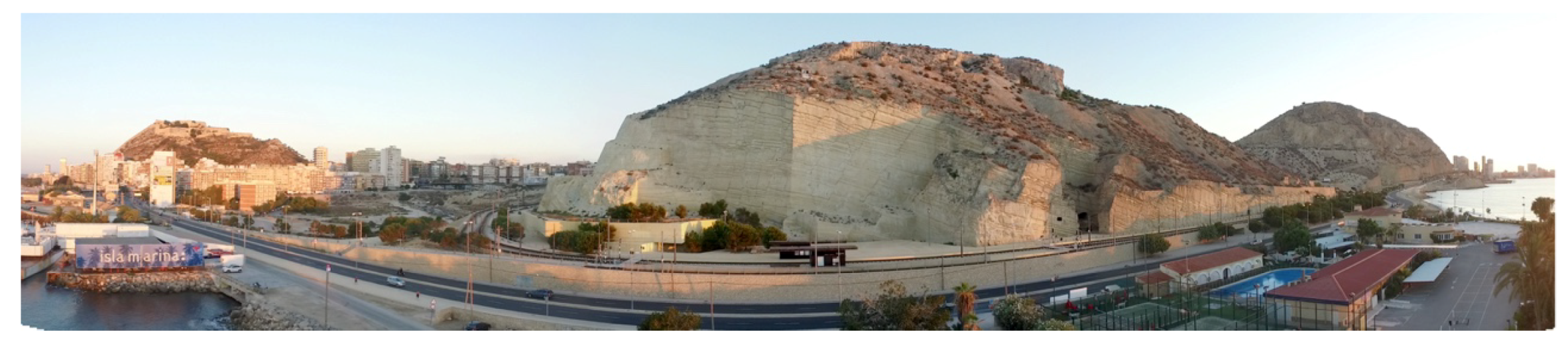
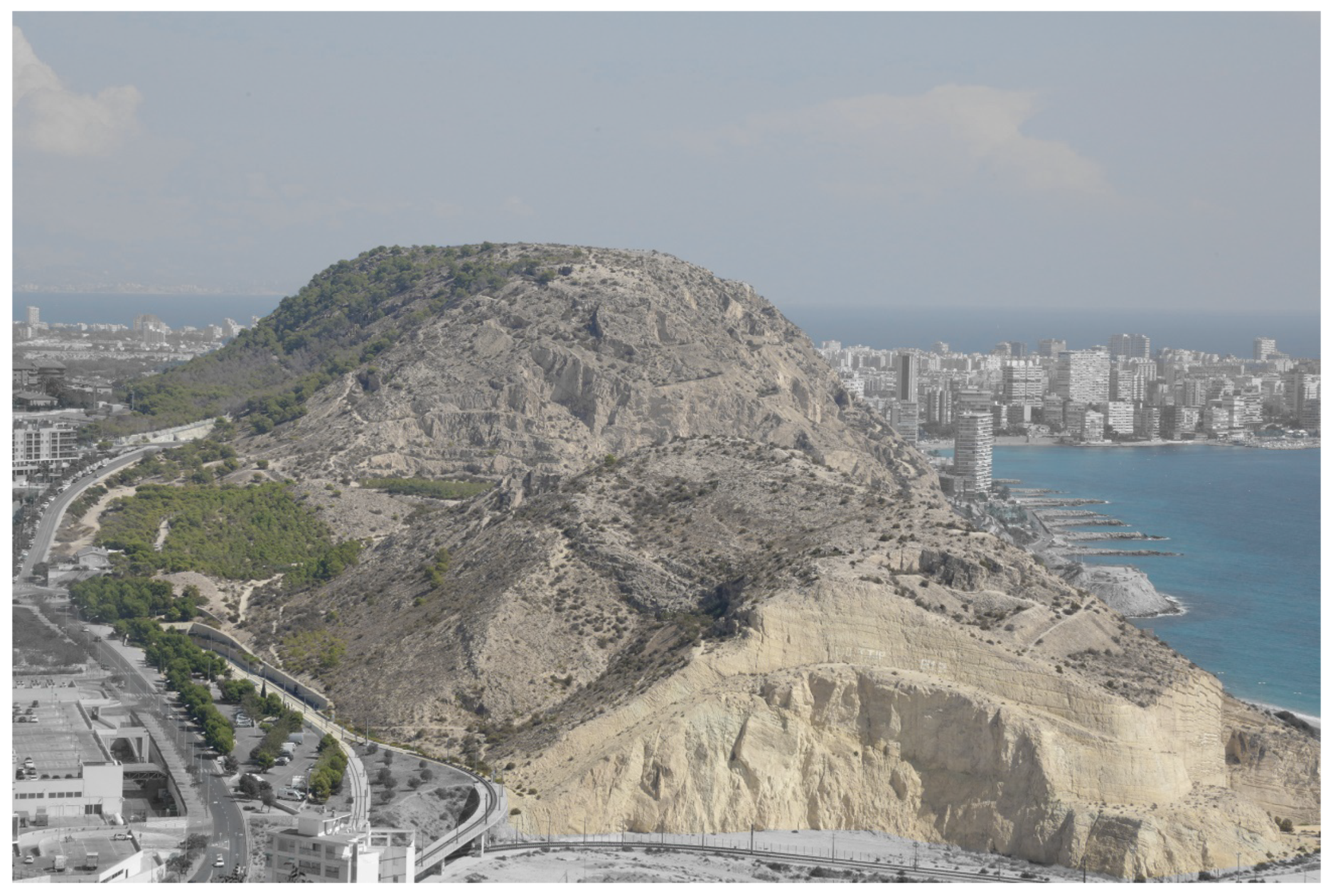
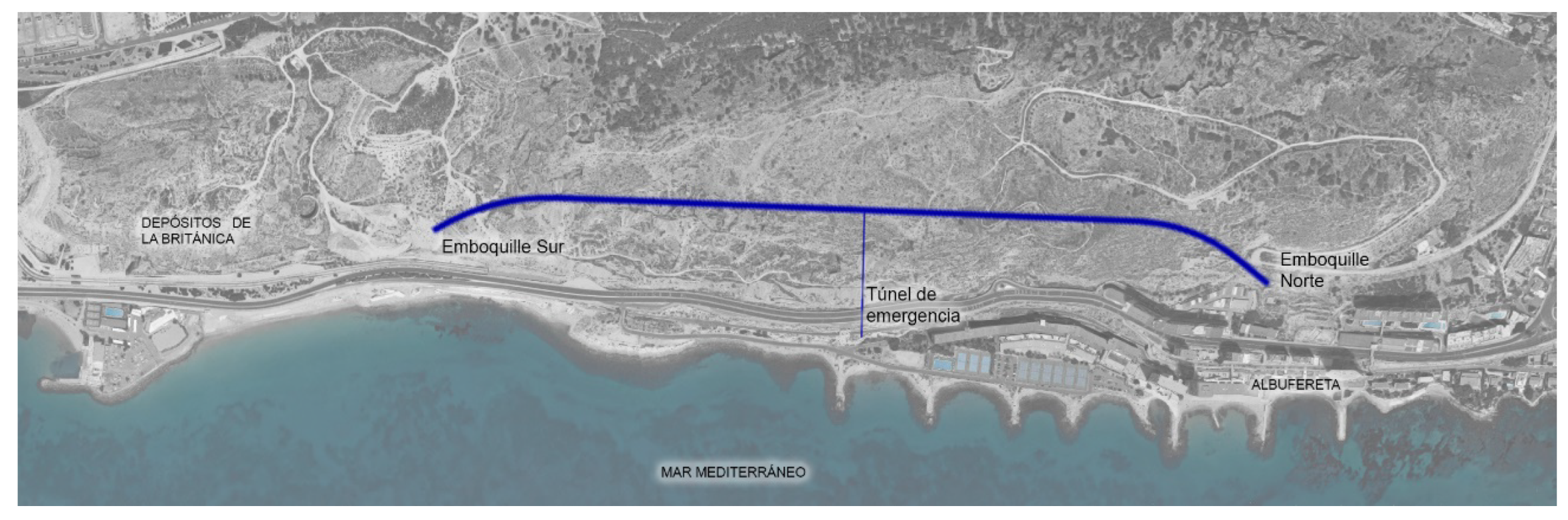
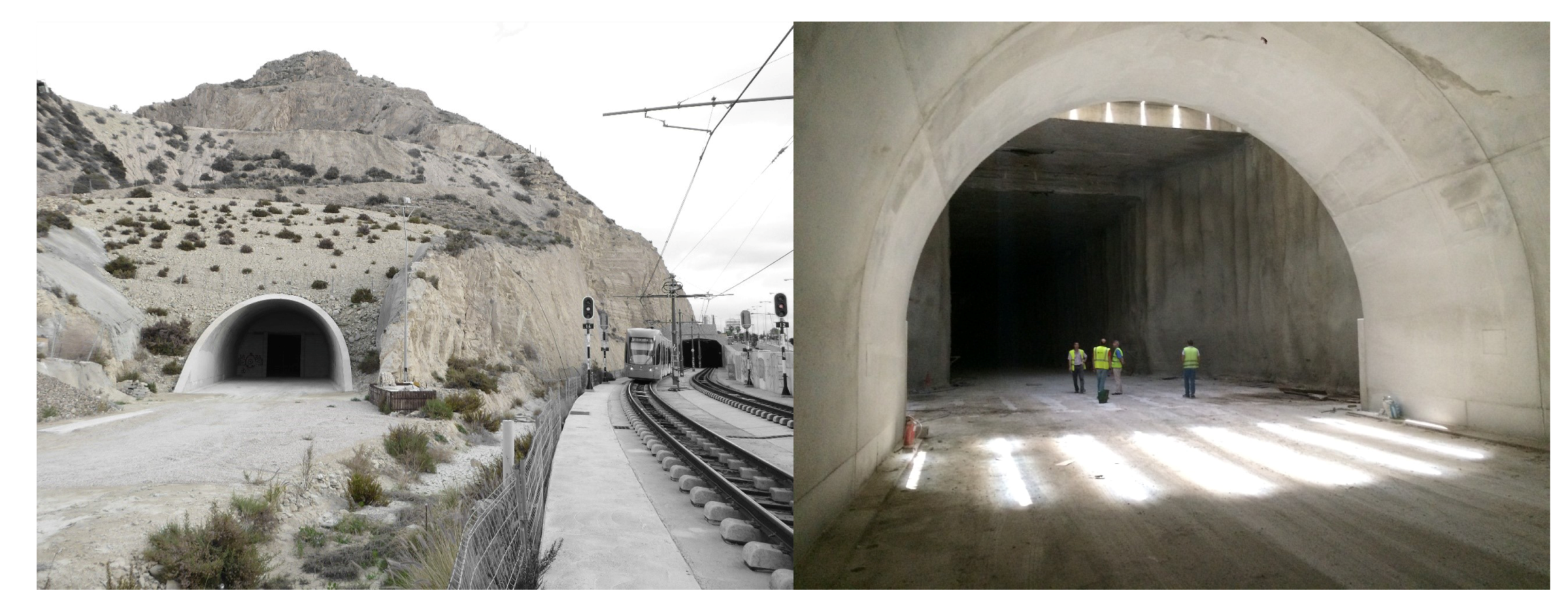
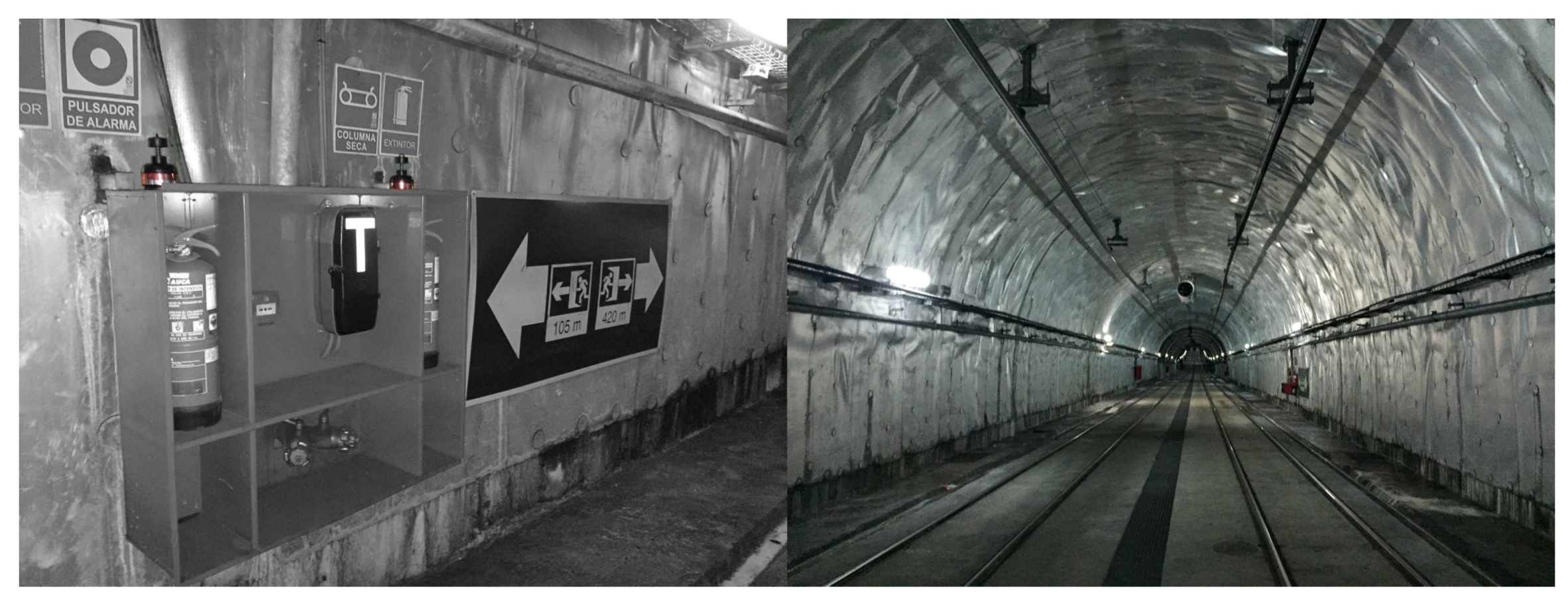
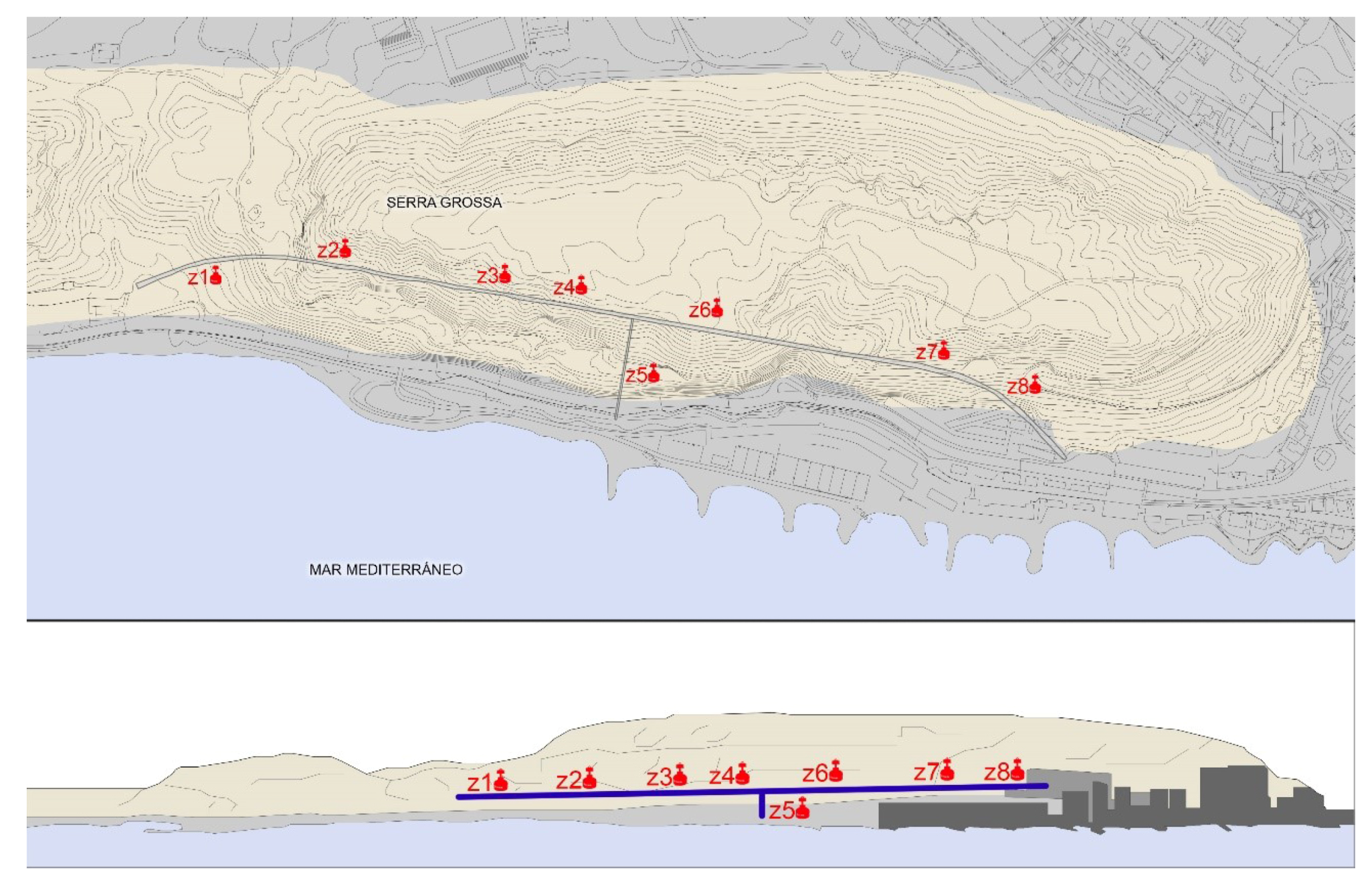
3.2. The Serra Grossa Railway Tunnel

The Serra Grossa is the largest mountain in the center of the city of Alicante. Inside is the railway tunnel, a modern civil infrastructure that forms part of the project to renovate the lines of the Alicante train. This construction belongs to the railway variant of line L1 in the section of Finca Adoc, which connects the city center to the northern part of Alicante province; Campello, Villajoyosa, Benidormm, or Altea (Figure 7).
Work on this tunnel began in 2008 but was paralyzed years later and has remained so until day, due to insufficient liquidity to complete the work. As a consequence, the excavation is almost completed, with the absence of the entrance or northern emboquille. Until the end of the work, the line that runs northwards from the center of Alicante takes advantage of the corridor of an old FEVE line, which in the future will be conditioned and equipped as a green area within the project “Landscape and urban integration of the TRAM as it passes through the Serra Grossa” (Figure 8).
The Serra Grossa tunnel has a total length of 1470 m, of which 30 m is a false tunnel at the southern mouth, 1315 m is a mine tunnel made with a tunnel boring machine and 125 m of the tunnel at the northern mouth was constructed between screens using the “cut and cover” system. This technique, also known as false tunneling, is used when the surface is very close and the sides have to be reinforced with piles prior to concreting [51].
The mine tunnel has a typical section with a vault that has an inside radius of 4.67 m and straight gables with heights of 2.39 m in. The free section inside the tunnel is 50.5 m 2 and has two evacuation passages with a useful width of 1.20 m. There is an evacuation gallery or emergency tunnel, perpendicular to the main one, that is 144 m long and 12 m 2 in section, which runs from the inside of the tunnel to the current railway platform, which is the future pedestrian promenade.
The terrain in which the tunnel is located corresponds to bioclastic calcarenites with variable foundations and tertiary loams that have undergone some tectonic processes. These tertiary loams correspond to materials that present worse geotechnical characteristics and are in the final area of the tunnel in the mine, along a small section of 90 m in length (Figure 9).
The construction of the tunnel was conditioned by the type of rock present in the mountain range (San Julián Stone), mostly calcarenites, and the presence of humidity in the mountain as Artemio Cuenca Payá explains in his article “Study of a rock-fall phenomenon in the San Julián Mountain (Alicante)” [52].
The construction of the mine tunnel was planned using conventional methods, with mechanical equipment used as the excavation system. The tunnel has a total of five support sections based on the placement of bolts, trusses, and shotcrete. With the starting conditions, the excavation of the saw was performed using tunnel boring machines using stretches of bats of 10 m.
During the preparation of the route of the tunnel inside the Serra Grossa, a series of geotechnical studies of the mountain at different points were made. These tests were conducted by the company ITC (Technical Construction Institute). The conclusions of the study show the great fracturing that exists in the different strata, as in Benacantil Mount, with a great presence of calcarenite: fillings up to 1 m deep, coarse-grained calcarenite rock with very fractured sections up to 1.80 m, fine grain calcarenite rock with fractured sections every 60 cm up to 2.4 m, and coarse-grained calcarenite rock with fractures every meter in the following substrates.
The soft calcarenite of the mountain has been used for the construction of buildings throughout the province, with several hillsides that have served as quarries. The church of Santa Maria in Alicante was built using this rock as the construction material. In 1929, the mountain was no longer used as a quarry. Due to the great fracturing of the massif, on 24 November 1984, the detachment of approximately 2800 tons of calcarenites occurred, which is the most important geological fact suffered in the last years.

4. Comparison of Air Quality. Radon Gas as a Control Element

Radon gas is an element found in the interior of buildings, especially underground ones, as they are in direct contact with the ground. The compared tunnels show two different conditions, that of Benacantil Mount, a tunnel with all the ventilation measures, and that of Serra Grossa, a tunnel in the phase prior to the commissioning of the building.
The comparison develops the hypothesis of the need to improve the ventilation in order to achieve a better indoor air quality in underground buildings, using radon gas as an indicator. That is, the accumulation of radon in both constructions will serve as an element to test the air renewal, as the presence of radon gas can be directly related to the ventilation.
In both cases, the system used in the tunnel for measuring radon gas was the electret ionic chamber (CIE), a system that combines a camera with a device that simultaneously functions as an electric field generator and a sensor. The system used is the Eperm, with the camera variant-electret and short-short.

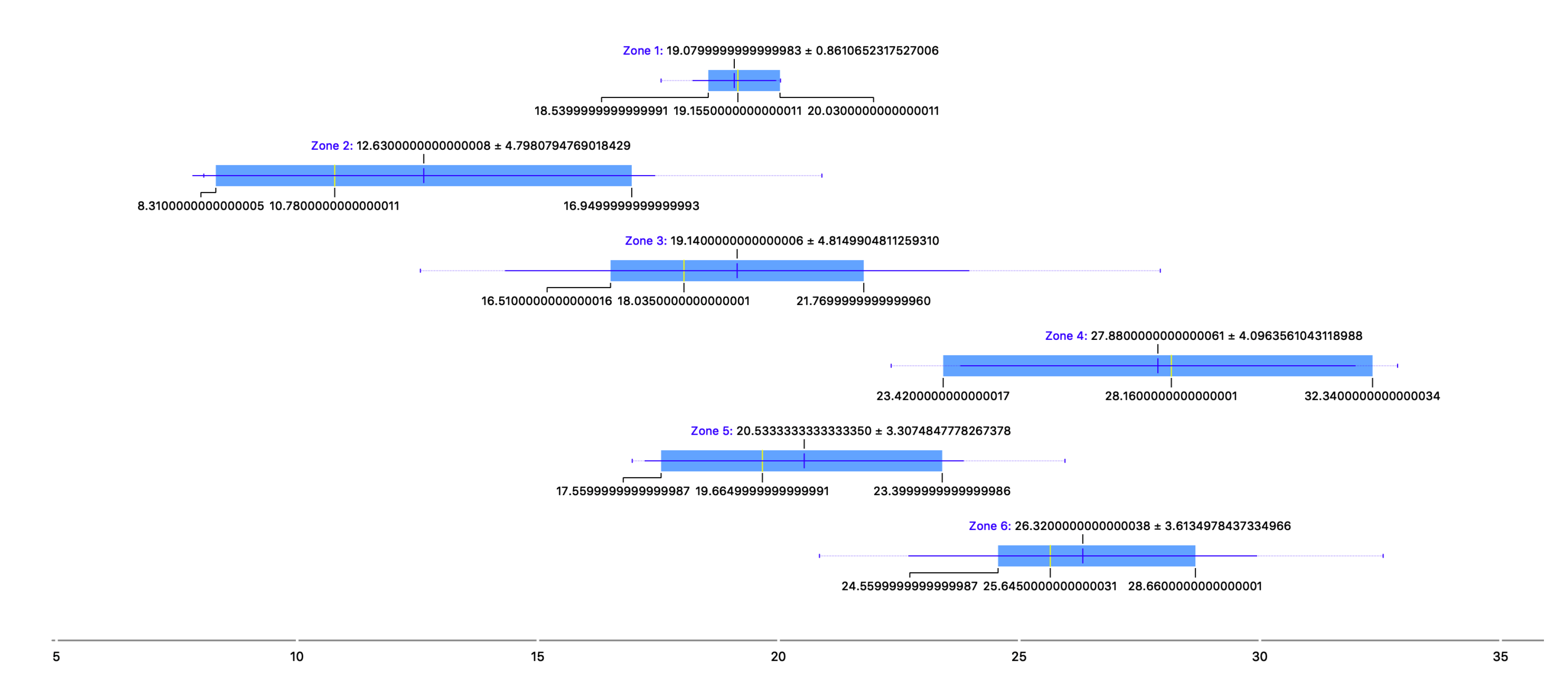
4.1. Study of Air Quality in the Benacantil Mount Tunnel

The study was conducted to measure the amount of radon gas inside the Benacantil Mount tunnel (Figure 10), which connects the Marq–Castillo stops with the center of Alicante—Luceros—and in the future, will lead to the Renfe stop. It was performed on 9 and 17 June 2016.
The data collection and process management inside the tunnel were performed thanks to the collaboration of the company FGV, which is in charge of the maintenance of the TRAM in Alicante. For reasons of use, the placement and collection of cameras to perform the study had to be done at midnight, as there are safety protocols in which there can be no people when trains are in motion.
The measurements were performed under normal conditions of use inside the tunnel, i.e., trains running and active mechanical ventilation means. For this reason, the air renewal was high and the amount of radon gas present was predictably low, an aspect that was intended to be verified.
The tunnel has an average depth of 15 m and connects, through a 1700 m duct, to the TRAM stop points at the foot of the castle (Marq–Castillo), as well as Mercado and Luceros to the future Renfe stop, which, although not yet connected to tracks, the excavation has been performed. The survey sites correspond to the following areas within the tunnel, as shown in Figure 11.
  • Zone 1
  • Zone 2
  • Zone 3
  • Zone 4
  • Zone 5
  • Zone 6
The tunnel, despite being 20 m underground in its deepest area, has a connection to the outside at its exit from the city center towards the north when it enters the Benacantil Mount. This, together with the large ventilation systems and the continuous movement of trains, generates a constant air renewal in the interior.

4.1.1. Data Collection Process in the Benacantil Mount Tunnel

The data collection phase lasted eight days from the introduction of the cameras on 9 June 2016, and the locations of the cameras were chosen with the premise of studying the maximum number of different zones. Fire equipment was used as a support for the placement of the chambers inside the tunnel, as the distances to the exits are marked in the fire equipment in case of an emergency, and because they served to protect the measuring elements from the strong air currents generated by the trains.
During the days in which the study was conducted from 9 June 2016, both the placement and the collection of cameras took place at approximately 12 o’clock at night. The average temperatures recorded in the city of Alicante during these days were between 23.2 °C and 26.8 °C. Being underground, the temperature inside the tunnel was practically constant at 20 °C, and under these conditions precipitations were not relevant for ionization.

4.1.2. Results Obtained in the Study of Benacantil Mount

The study lasted eight days starting on 9 June 2016, and the cameras were placed by covering the length of the tunnel to provide data from different areas, depending on the composition of the terrain or the constructive form, with which the tunnel was made in each section, being different both in Benacantil Mount and the avenues of the city. Figure 12 shows the values obtained from the measurement.

4.2. Study of Air Quality in the Serra Grossa Tunnel

The planning of the study to measure the quality of the indoor air related to radon gas as an indicator was performed in the Serra Grossa tunnel, which began by establishing the constructive characteristics of the installation. The redesign of the areas to be sampled took the three parts that make it up into account: the tunnel in the mine, the secondary exhaust outlet perpendicular to the main core and the northern outlet that is walled up but with an upper skylight, which makes it an isolated ventilated area. Therefore, there are three possible air inlets: the north outlet, the exhaust outlet, and the south outlet. The tunnel is paralyzed, and therefore the movement of air inside is very low, except for these three mentioned areas.
The measurement zones correspond to the following points (Figure 13):
  • Zone 1
  • Zone 2
  • Zone 3
  • Zone 4
  • Zone 5
  • Zone 6
  • Zone 7
  • Zone 8
The design of the tunnel and its circumstances have allowed the movement of people and vehicles inside to be minimal during the 12 days of study, as only the surveillance services that guard the construction project were allowed in.

4.2.1. Data Collection Process in the Serra Grossa Tunnel

The duration of the study was 12 days, starting on 12 June 2016, and the measurement sites were chosen with the premise of covering the largest possible area, so that they were equidistant from one another. A vehicle was used to travel through the tunnel, which facilitated this task and made it possible to define the exact location of each chamber by taking measurements in kilometers.
For the study performed in this tunnel, in addition to the short chambers and electrets, a series of special boxes were used that allowed symmetrical measurements to be made between two devices simultaneously in order to verify the results. Three measurements were made in these areas: one with a single short camera and two with twin cameras within this system, which allowed for measurements in parallel. The places where this technique was used were Zones 4, 5, and 6.
Access to the Serra Grossa tunnel for the placement and collection of measuring equipment, as in the Benacantil Mount tunnel, was conducted in only two days due to the availability of the company guarding the tunnel. The site study began on 30 June 2016 and lasted approximately 12 days. The average temperatures recorded in the city of Alicante on these days of the study were between 24 °C and 27 °C and there was no precipitation. As it is an excavated site, the temperature is constant and the precipitation is not important, because it does not affect the interior of the tunnel [53]. The temperature inside the tunnel is approximately 18 °C, which is slightly lower than the Benacantil Mount tunnel due to the scarce renewal of air coming from the outside.

4.2.2. Results Obtained in the Serra Grossa Study

The representation of the radon gas results present in the Serra Grossa tunnel environment is provided by means of a comparative table, which shows the different measurement areas and the values of the environmental radon concentration obtained in Bq/m3. Figure 14 shows a representative graph of these areas with the obtained values.

5. Discussion of Results

The main objective of this research is to demonstrate the need for ventilation in buried works. In this case, a comparison is made between two railway tunnels of the urban fabric of the city of Alicante: one of them in operation (the Benacantil Mount) and another in an excavation state (Serra Grossa). These elements are compared due to their different states: one active and one under construction.

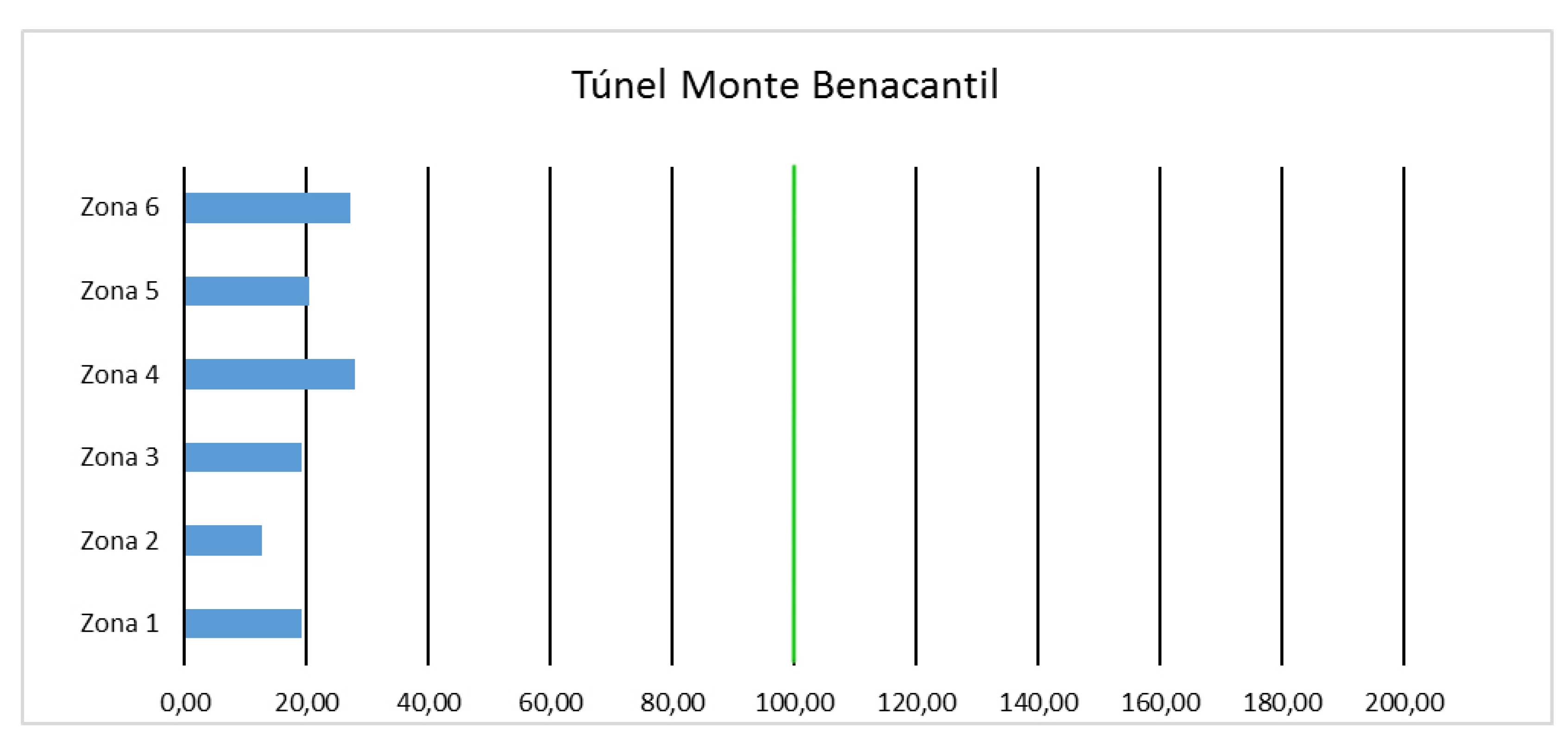
5.1. Summary of the Results of the Benacantil Mount Tunnel Measurement

The measurements obtained for the amount of radon gas inside the tunnel were low; the placement of the large air extraction equipment, together with the movement of trains coming from the outside, makes the air continuously renewed, which resulted in the low presence of this gas.
As shown by the averages of the values obtained (Figure 15), the results are very low and homogeneous in the tunnel, with all results being lower than 100 Bq/m 3 . Therefore, in coherence with the criteria used, this is considered a place without the need for intervention or precautionary measures.
From the results obtained during the study in the tunnel, a comparison is made in the different places measured with the short camera and short electret. The measurement areas have a radon gas concentration less than 100 Bq/m 3 , so no follow-up work is necessary. It can then be summarized that the tunnel is ventilated and that the air extraction and renewal measures work correctly in this architectural construction.

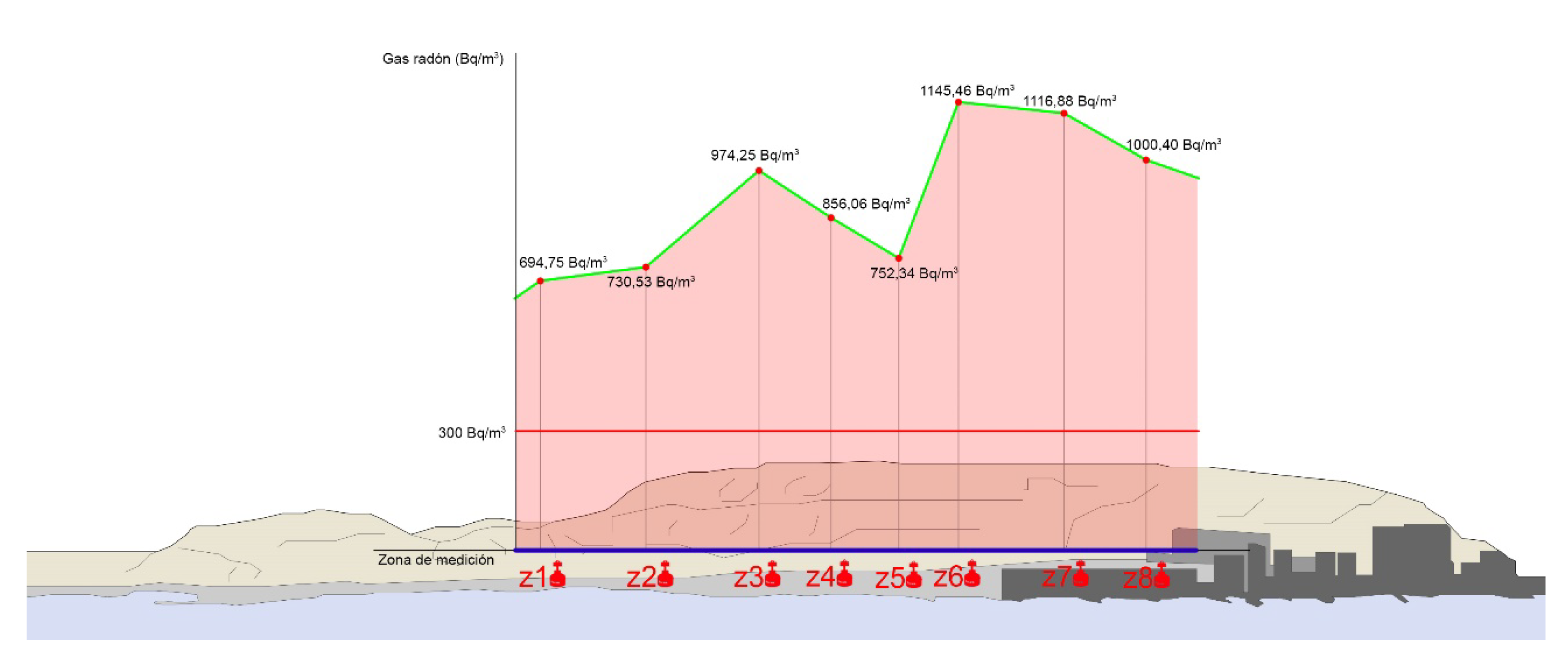
5.2. Summary of the Results of the Serra Grossa Tunnel Measurement

From the results obtained during the study in the tunnel, a comparison is made in the different places measured with a short camera and short electret. As shown in Table 1, the mean radon gas values in the air reach 1145.46 Bq/m 3 at 800 m from the southern entrance (Measurement Zone 6), and the lowest value obtained corresponds to a location 100 m from the southern entrance (Zone 1), where the amount of mean radon obtained is 694.75 Bq/m 3 .
The results obtained inside the tunnel show a high average amount of radon gas inside, which is explained by the little air movement that is generated. The three possible entrances (main entrance, emergency exit and northern skylight) being approximately 500 m away from one another prevents proper ventilation in these conditions.
As summarized in Figure 16 and Figure 17, the average values obtained in the different measurement zones comfortably exceed the threshold of 300 Bq/m 3 , established within this study as the value at which it is necessary to take corrective ventilation measures. This installation should not be used by people because its concentration of radon gas is excessively dangerous to their health. In the future, when it comes into operation and with the mechanical means of ventilation, this unhealthy problem will be more than solved [54].

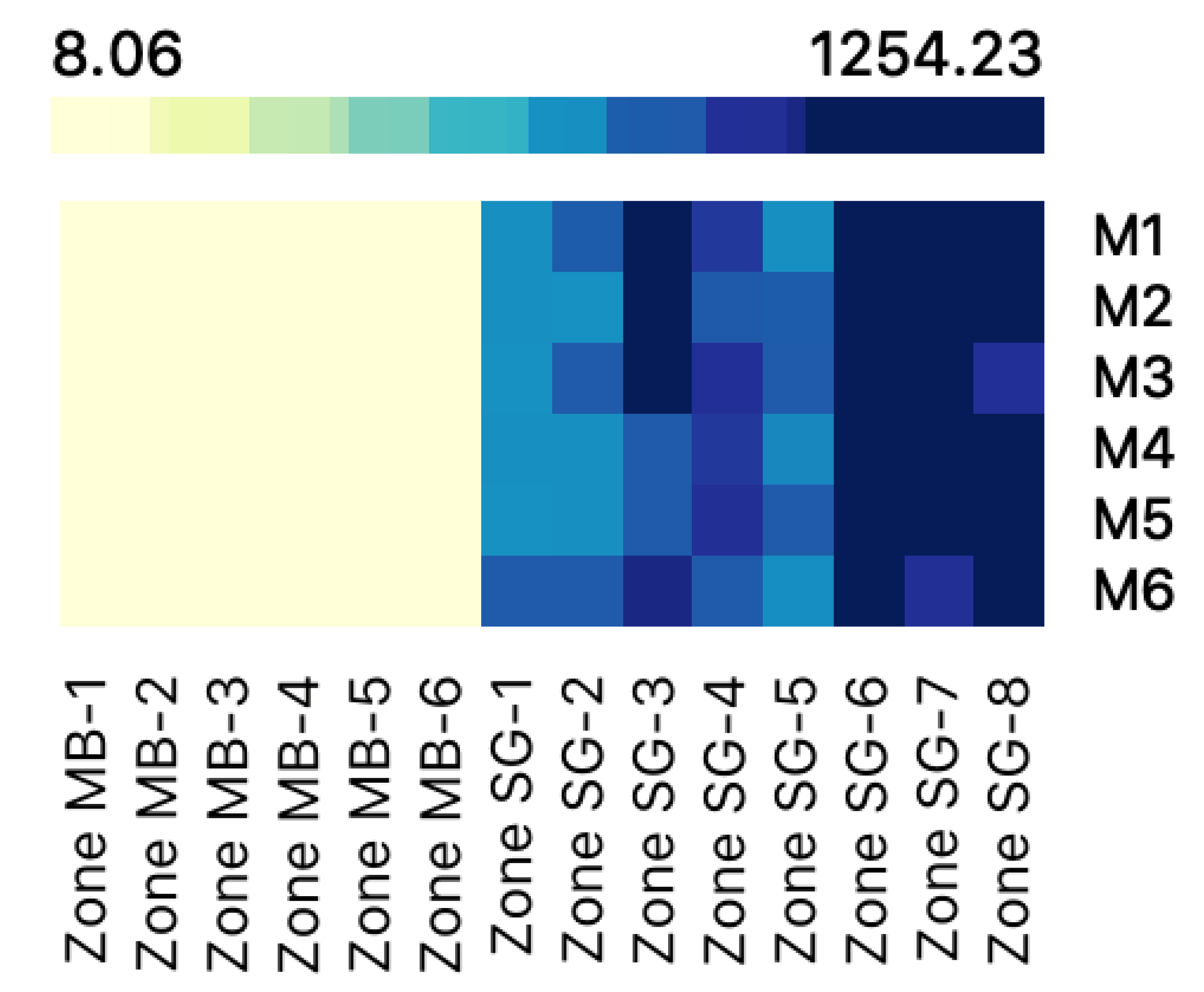
5.3. Comparison of Results

The results obtained are consistent with the central hypothesis of this research; the actions that have contact with the terrain and scarce ventilation may show, as is the case of this tunnel, amounts of radon gas that are very harmful to health, even in places that are established as low exposure within the Marna map.
The measurements obtained in both tunnels are representative of the initial hypothesis, i.e., buried buildings are likely to harbor high amounts of radon gas and therefore the air quality is low. Under normal conditions, these constructions usually have mechanical ventilation elements that are capable of renewing the air and, therefore, improving its quality. Figure 18 shows the comparison of the results obtained in both tunnels in Bq/m 3 .
The land and construction materials used in the buildings are the two largest emitters of radon gas in the buildings. The first is always imposed by the location and the second depends on other project decision factors. Buried constructions are considered very relevant, as they have a direct contact with the building materials in all enclosures.
The study presented shows two constructions with similar technical characteristics and terrain environments, with the exception that one is active (the Benacantil Mount tunnel) and the other in the construction phase (the Serra Grossa tunnel). Radon gas being an element found in the environment can be considered an indicator of the renewal of air inside a building. The different conditions of both buildings make it possible to compare the need for air ventilation in buried environments.
The Benacantil Mount railway tunnel is a construction that is currently in use, with constant train movement, which generates large currents and good ventilation being the optimal air renewal. That is why the measurements obtained from the amount of radon gas inside the tunnel have been low.

6. Conclusions

It is demonstrated that the Benacantil Mount tunnel has low amounts of radon accumulation, as the air renewal elements work correctly.
The Serra Grossa tunnel obtains values between 694.75 and 1145.46 Bq/m 3 , quadrupling the threshold of 300 Bq/m 3 , established by the WHO as the value from which it is necessary to take corrective ventilation measures.
A comparison of the two tunnels shows that the lithological zone is susceptible to radon gas accumulation and dangerous for the people inside.
It is concluded that radon gas is an indicator of the good air quality of a site. In addition, ventilation in railway tunnels (mechanical and natural) allows air renewal and improves air quality.

7. Future Lines of Research

The results obtained in the work carried out have provided a set of conclusions from which starting points are drawn for future lines of research, both in the actions to be taken to protect existing buildings from radon gas and the future measures to be incorporated into the construction. The interest and complexity of the subjects studied deserve to continue the work and the following lines of research are proposed for the future.
  • In the field of construction, new techniques must be implemented that incorporate greater protections and barriers that prevent the entry of radon gas produced by ground contact.
  • Construction materials should focus on achieving non-generation of radon gas by moving away from the elements of their chain of semidesintegration in their composition.
  • Regulations concerning the maximum permitted quantities of radon gas in buildings, as well as measures to be taken from certain concentration levels, must be developed and made mandatory to control the presence of this gas in buildings. It has been found that the levels of this gas can be excessively high even in areas not considered to be at risk.
  • Measures should be implemented for constructions located on the land with high values of radon gas concentration to help reduce the dose of human exposure. These measures should focus both on ventilation and indoor air renewal and direct methods of capturing and expelling gas from inside buildings.
  • In the field of radioprotection, the dose that a person can support in particular cases should be investigated using appropriate dosimetry models.
  • In the particular case of the study shown, we intended to measure the tunnel of the Serra Grossa Mountain after the works and already in operation, to check the proper ventilation and, therefore, air quality.

Author Contributions

The work presented here was developed via collaboration among all authors. All authors have contributed to, seen, and approved of the manuscript.

Funding

This research received no external funding.

Acknowledgments

The authors of this paper thank the University of Alicante for the grant that allowed part of this research.

Conflicts of Interest

The authors declare no conflicts of interest.

References

  1. Tung, T.C.; Chan, D.W.; Burnett, J. An empirical radon emanation model for residential premises. Build. Environ. 2005, 40, 1566–1571. [Google Scholar] [CrossRef]
  2. Collignan, B.; Powaga, E. Procedure for the characterization of radon potential in existing dwellings and to assess the annual average indoor radon concentration. J. Environ. Radioact. 2014, 137, 64–70. [Google Scholar] [CrossRef] [PubMed]
  3. Istrate, M.A.; Catalina, T.; Cucos, A.; Dicu, T. Experimental Measurements of VOC and Radon in Two Romanian Classrooms. Energy Proced. 2016, 85, 288–294. [Google Scholar] [CrossRef] [Green Version]
  4. Porstendörfer, J. Properties and behaviour of radon and thoron and their decay products in the air. J. Aerosol Sci. 1994, 25, 219–263. [Google Scholar] [CrossRef]
  5. Järnström, H. Reference Values for Building Material Emissions and Indoor Air Quality in Residential Buildings; Pub. Prima Oy: Helsinki, Finland, 2008. [Google Scholar]
  6. Webb, P.C. Radioactivity in geology: Principles and applications by E. M. Durrance (Ellis Horwood series in Geology), Ellis Horwood Ltd, Chichester, England, 1986. no. of pages: 441. price: £59.50 (hardback). Geol. J. 2007, 23, 104–105. [Google Scholar] [CrossRef]
  7. International Atomic Energy Agency. Guidelines for Radioelement Mapping Using Gamma Ray Spectrometry Data; Nuclear Fuel Cycle and Materials Section International Atomic Energy Agency: Vienna, Austria, 2003; p. 179. [Google Scholar]
  8. Nagaraja, K.; Prasad, B.S.N.; Madhava, M.S.; Chandrashekara, M.S.; Paramesh, L.; Sannappa, J.; Pawar, S.D.; Murugavel, P.; Kamra, A.K. Radon and its short-lived progeny: Variations near the ground. Radiat. Meas. 2003, 36, 413–417. [Google Scholar] [CrossRef]
  9. Wanty, R.B. Field Studies of Radon in Rocks, Soils, and Water; L.C.S. Gundersen: Washington, DC, USA, 1991. [Google Scholar]
  10. Edwards, R.D.; Jurvelin, J.; Koistinen, K.; Saarela, K.; Jantunen, M. VOC source identification from personal and residential indoor, outdoor and workplace microenvironment samples in EXPOLIS-Helsinki, Finland. Atmos. Environ. 2001, 35, 4829–4841. [Google Scholar] [CrossRef]
  11. Tchorz-Trzeciakiewicz, D.E.; Klos, M. Factors affecting atmospheric radon concentration, human health. Sci. Total. Environ. 2017, 584–585, 911–920. [Google Scholar] [CrossRef]
  12. Jönsson, G. Radon gas—where from and what to do? Radiat. Meas. 1995, 25, 537–546. [Google Scholar] [CrossRef]
  13. Kim, S.H.; Hwang, W.J.; Cho, J.S.; Kang, D.R. Attributable risk of lung cancer deaths due to indoor radon exposure. Ann. Occup. Environ. Med. 2016, 28, 8. [Google Scholar] [CrossRef] [Green Version]
  14. 90/143/EURATOM. Recommendation of the EURATOM Commission of 21 February 1990 on the Protection of the General Public against the Dangers of Exposure to Radon inside Buildings; Europe Union, 1990; Available online: https://op.europa.eu/en/publication-detail/-/publication/260b2024-21d9-4de5-ae3f-d7867a15d221/language-en (accessed on 23 October 2019).
  15. Lavi, N.; Steiner, V.; Alfassi, Z.B. Measurement of radon emanation in construction materials. Radiat. Meas. 2009, 44, 396–400. [Google Scholar] [CrossRef]
  16. Maestre, C.R.; Yepes, S.C. Detection and importance of the presence of Radon Gas in buildings. Int. J. Eng. Tech. Res. (IJETR) 2016, 4, 67–70. [Google Scholar]
  17. Andersson, K.G. Radioactivity in the Environment. In Airborne Radioactive Contamination in Inhabited Areas; Elservier: London, UK, 2009; Volume 15. [Google Scholar]
  18. United Nations; Scientific Committee on the Effects of Atomic Radiation. Sources and Effects of Ionizing Radiation: United Nations Scientific Committee on the Effects of Atomic Radiation: UNSCEAR 2000 Report to the General Assembly, with Scientific Annexes; Elsevier Science: Amsterdam, The Netherlands, 2000. [Google Scholar]
  19. Cristobo, J.J.J.L. Medición de la Concentración de Gas 222Rn en el Interior de Edificios; USC. Departamento de Física de las Partículas: Compostela, Spain, 2006; p. 64. [Google Scholar]
  20. Cuvier, A.; Panza, F.; Pourcelot, L.; Foissard, B.; Cagnat, X.; Prunier, J.; van Beek, P.; Souhaut, M.; Roux, G.L. Uranium decay daughters from isolated mines: Accumulation and sources. J. Environ. Radioact. 2015, 149, 110–120. [Google Scholar] [CrossRef] [PubMed]
  21. Szabó, K.Z.; Jordan, G.; Horváth, Á.; Szabó, C. Mapping the geogenic radon potential: Methodology and spatial analysis for central Hungary. J. Environ. Radioact. 2014, 129, 107–120. [Google Scholar] [CrossRef]
  22. Collignan, B.; Powaga, E. Impact of ventilation systems and energy savings in a building on the mechanisms governing the indoor radon activity concentration. J. Environ. Radioact. 2017. [Google Scholar] [CrossRef]
  23. Boerma, M.; Sridharan, V.; Mao, X.W.; Nelson, G.A.; Cheema, A.K.; Koturbash, I.; Singh, S.P.; Tackett, A.J.; Hauer-Jensen, M. Effects of ionizing radiation on the heart. Mutat. Res. Mutat. Res. 2016, 770, 319–327. [Google Scholar] [CrossRef] [Green Version]
  24. Bhattacharya, S.; Asaithamby, A. Ionizing radiation and heart risks. Semin. Cell Dev. Biol. 2016, 58, 14–25. [Google Scholar] [CrossRef]
  25. Ravanat, J.L.; Douki, T. UV and ionizing radiations induced DNA damage, differences and similarities. Radiat. Phys. Chem. 2016, 128, 92–102. [Google Scholar] [CrossRef]
  26. Amber, I.; O’Donovan, T.S. Natural convection induced by the absorption of solar radiation: A review. Renew. Sustain. Energy Rev. 2018, 82, 3526–3545. [Google Scholar] [CrossRef]
  27. Rizo-Maestre, C.; Chinchón Yepes, S. Radon Gas-Hazardous element for human life really found in the environment. In Proceedings of the 2nd International Conference on Green Materials and Environmental Engineering, Phuket, Thailand, 20–21 December 2015; Editor Atlantis Press: Hyderabad, India, 2015; pp. 60–62. [Google Scholar]
  28. Consejo de Seguridad Nuclear. Dosis de Radiación; Consejo de Seguridad Nacional: Madrid, España, 2010; p. 18. [Google Scholar]
  29. Barbosa-Lorenzo, R.; Ruano-Ravina, A.; Caramés, S.C.; Barros-Dios, J.M. Radón residencial y cáncer de pulmón. Un estudio ecológico en Galicia. Med. ClÍNica 2015, 144, 304–308. [Google Scholar] [CrossRef]
  30. Nastro, V.; Carni, D.L.; Vitale, A.; Lamonaca, F.; Vasile, M. Passive and active methods for Radon pollution measurements in historical heritage buildings. Measurement 2018, 114, 526–533. [Google Scholar] [CrossRef]
  31. Li, P.; Zhang, R.; Gu, M.; Zheng, G. Uptake of the natural radioactive gas radon by an epiphytic plant. Sci. Total. Environ. 2018, 612, 436–441. [Google Scholar] [CrossRef] [PubMed]
  32. Zeeb, H. International Radon Project. Survey On Radon Guidelines, Programmes and Activities; WHO HSE/PHE/RAD, 2007; p. 49. Available online: https://www.who.int/ionizing_radiation/env/radon/IRP_Survey_on_Radon.pdf (accessed on 23 October 2019).
  33. NTP 440: Radón en Ambientes Interiores; Ministerio de Trabajo y Asuntos Sociales: Madrid, Spain, 1999.
  34. Amgarou, K. Long-Term Measurements of Indoor Radon and Its Progeny in the Presence of Thoron Using Nuclear Track Detectors a Novel Approach; Universitat Autònoma de Barcelona: Barcelona, Spain, 2003. [Google Scholar]
  35. Yoon, J.Y.; Lee, J.D.; Joo, S.W.; Kang, D.R. Indoor radon exposure and lung cancer: A review of ecological studies. Ann. Occup. Environ. Med. 2016, 28, 15. [Google Scholar] [CrossRef] [PubMed]
  36. Cambeses, A.; Garcia-Casco, A.; Scarrow, J.H.; Montero, P.; Pérez-Valera, L.A.; Bea, F. Mineralogical evidence for lamproite magma mixing and storage at mantle depths: Socovos fault lamproites, SE Spain. Lithos 2016, 266–267, 182–201. [Google Scholar] [CrossRef]
  37. Duval, J.S. Use of aerial gamma-ray data to estimate relative amounts of radon in soil gas. In Field Studies of Radon in Rocks, Soils, and Water; CRC Press: Boca Raton, FL, USA, 1991; pp. 155–161. ISBN 9780873719551. [Google Scholar]
  38. Tanner, A.B. Methods of characterization of ground for assessment of indoor radon potential at a site. In Field Studies of Radon in Rocks, Soils, and Water; 1991; Available online: https://inis.iaea.org/search/searchsinglerecord.aspx?recordsFor=SingleRecord&RN=23074574 (accessed on 23 October 2019).
  39. Ielsch, G.; Cushing, M.E.; Combes, P.; Cuney, M. Mapping of the geogenic radon potential in France to improve radon risk management: Methodology and first application to region Bourgogne. J. Environ. Radioact. 2010, 101, 813–820. [Google Scholar] [CrossRef]
  40. Kemski, J.; Siehl, A.; Stegemann, R.; Valdivia-Manchego, M. Mapping the geogenic radon potential in Germany. Sci. Total. Environ. 2001, 272, 217–230. [Google Scholar] [CrossRef]
  41. Neznal, M.; Matolín, M.; Barnet, I.; Mikšová, J. The new method for assessing the radon risk of building sites. In Prace Ceskeho Geologickeho Ustavu; 2004; pp. 7–47. Available online: https://www.radon-vos.cz/pdf/metodika.pdf (accessed on 23 October 2019).
  42. Buttafuoco, G.; Tallarico, A.; Falcone, G. Mapping Soil Gas Radon Concentration: A Comparative Study of Geostatistical Methods. Environ. Monit. Assess. 2007, 131, 135–151. [Google Scholar] [CrossRef]
  43. Olaya, M.; Borja, F. El Código Técnico de la Edificación en España (CTE) Medidas correctoras destinadas a frenar la entrada de radón en los edificios. Investig. Campo Como Exp. Piloto Espa NA. 2007. Available online: https://www.radon-vos.cz/pdf/metodika.pdf (accessed on 23 October 2019).
  44. Cepedal, A.; Fuertes-Fuente, M.; Martín-Izard, A.; García-Nieto, J.; Boiron, M.C. An intrusion-related gold deposit (IRGD) in the NW of Spain, the Linares deposit: Igneous rocks, veins and related alterations, ore features and fluids involved. J. Geochem. Explor. 2013, 124, 101–126. [Google Scholar] [CrossRef]
  45. Rizo-Maestre, C.; Víctor, E. The Importance of Checking Indoor Air Quality in Underground Historic Buildings Intended for Tourist Use. Sustainability 2019, 11, 689. [Google Scholar] [CrossRef]
  46. Rizo-Maestre, C.; Víctor, E. The Radon Gas in Underground Buildings in Clay Soils. The Plaza Balmis Shelter as a Paradigm. Int. J. Environ. Res. Public Health 2018, 15, 1004. [Google Scholar] [CrossRef]
  47. Ruiz, R.A. Castellología medieval alicantina. Rev. Inst. Estud. Alicant. (IEA). Available online: https://www.iberlibro.com/buscar-libro/titulo/castellolog%EDa-medieval-alicantina-%E1rea-meridional/autor/azuar-ruiz/ (accessed on 23 October 2019).
  48. Rosser, P.; Quiles, I.; Limiñana, P.R. Sistema Defensivo Bajomedieval de la Villa Cristiana de Alicante, 1st ed.; Ayuntamiento de Alicante, 1996; Available online: https://www.radon-vos.cz/pdf/metodika.pdf (accessed on 23 October 2019).
  49. Colomer, M.B. Ereta del Benacantil. In Actuaciones Arqueol{ó}gicas en la Provincia de Alicante; 2000; ISBN 978-84-695-6558-2. Available online: https://dialnet.unirioja.es/servlet/articulo?codigo=809221 (accessed on 23 October 2019).
  50. Civera, I.A. Arquitecturas del TRAM Metrolopolitano de Alicante: La Estación de Luceros, Nueva Plaza en la Ciudad; Cátedra Demetrio Ribes UVEG-FGV, 2010; p. 48. Available online: http://150ferrocarrilalicante.catedradr.com/archivos/descargas/PDF_16_opt.pdf (accessed on 23 October 2019).
  51. Di, H.; Zhou, S.; Xiao, J.; Gong, Q.; Luo, Z. Investigation of the long-term settlement of a cut-and-cover metro tunnel in a soft deposit. Eng. Geol. 2016, 204, 33–40. [Google Scholar] [CrossRef]
  52. Payá, A.C. Estudio de un fenómeno de desprendimiento de rocas (rock-fall) en la Sierra de San Julián (Alicante). Investig. GeográFicas 1985, 3, 31–51. [Google Scholar] [CrossRef]
  53. Groves-Kirkby, C.J.; Crockett, R.G.M.; Denman, A.R.; Phillips, P.S. A critical analysis of climatic influences on indoor radon concentrations: Implications for seasonal correction. J. Environ. Radioact. 2015, 148, 16–26. [Google Scholar] [CrossRef] [PubMed] [Green Version]
  54. Miguel, M.G.T.S.; Matarranz, J.L.M.; de Mingo, R.G.; Cadierno, J.P.G.; Mahou, E.S. El Mapa Predictivo de Exposición al Radón en España; Editor Consejo de Seguridad Nuclear: Madrid, Spain, 2013; p. 102. [Google Scholar]
Figure 1. Panoramic view of Benacantil Mount and Serra Grossa (Source: Google Maps).
Sustainability 11 06205 g001
Figure 2. Panoramic view of Serra Grossa and Benacantil Mount taken with a drone flight. (Own source).
Sustainability 11 06205 g002
Figure 3. Image of the north face of Benacantil Mount from the TRAM of la Sangueta stop in Serra Grossa. (Own source).
Sustainability 11 06205 g003
Figure 4. Situation plan of the Benacantil Mount railway tunnel (Own source).
Sustainability 11 06205 g004
Figure 5. Left: Current image of Luceros Square, where the TRAM underground station of the same name is located. (Own source). Right: Photomontage of the tunnel under Alfonso X el Sabio avenue. (Own source).
Sustainability 11 06205 g005
Figure 6. Images corresponding to the construction phase of the tunnel as it passes between Benacantil Mount and Jaume II avenue, the tunnel boring machine in operation and the piling system. (Own source).
Sustainability 11 06205 g006
Figure 7. Image of the Serra Grossa from the Castle of Santa Bárbara. (Own source).
Sustainability 11 06205 g007
Figure 8. Google Maps image of Serra Grossa with the location of the railway tunnel. (Own elaboration).
Sustainability 11 06205 g008
Figure 9. Left: Image of the entrance or southern mouth of the Serra Grossa tunnel. (Own source). Right: Image of the north exit or emboquille. The snapshot corresponds to the day that the measuring equipment inside the tunnel was introduced, with the workers of the company guarding the project. (Own source).
Sustainability 11 06205 g009
Figure 10. Image of the tunnel during the data acquisition phase. Left: Measurement equipment inside the tunnel. (Own source). Right: Underground section of Benacantil Mount. (Own source).
Sustainability 11 06205 g010
Figure 11. Image of the measurement points inside the tunnel. (Own source).
Sustainability 11 06205 g011
Figure 12. Measurements obtained in the Benacantil Mount tunnel. The data variation is represented in Bq/m 3 . (Own source).
Sustainability 11 06205 g012
Figure 13. Plan and elevation of the tunnel where the arrangement of the measuring elements in Serra Grossa and Albufera can be observed. (Own source).
Sustainability 11 06205 g013
Figure 14. Measurements obtained in the Serra Grossa tunnel. The data variation is represented in Bq/m 3 . (Own source).
Sustainability 11 06205 g014
Figure 15. Representation of the average results obtained in the tunnel, measured in Bq/m 3 . Green reference of 100 Bq/m 3 . (Own source).
Sustainability 11 06205 g015
Figure 16. Comparative bar graph of the average results obtained in the places chosen for the study inside the Serra Grossa tunnel, measured in Bq/m 3 . In green is a reference of 100 Bq/m 3 , and in red is a reference of 300 Bq/m 3 (Own source).
Sustainability 11 06205 g016
Figure 17. Comparative bar graph of the results obtained in the Serra Grossa tunnel, measured in Bq/m 3 , superimposed on the elevation of the tunnel. (Own source).
Sustainability 11 06205 g017
Figure 18. Heat map comparing the results obtained in both tunnels for the presence of radon gas Bq/m 3 . The color gradient shows yellow as a low presence and blue as a high presence. (Own source).
Sustainability 11 06205 g018
Table 1. Summary of the measurements conducted in the Serra Grossa tunnel. (Own source).
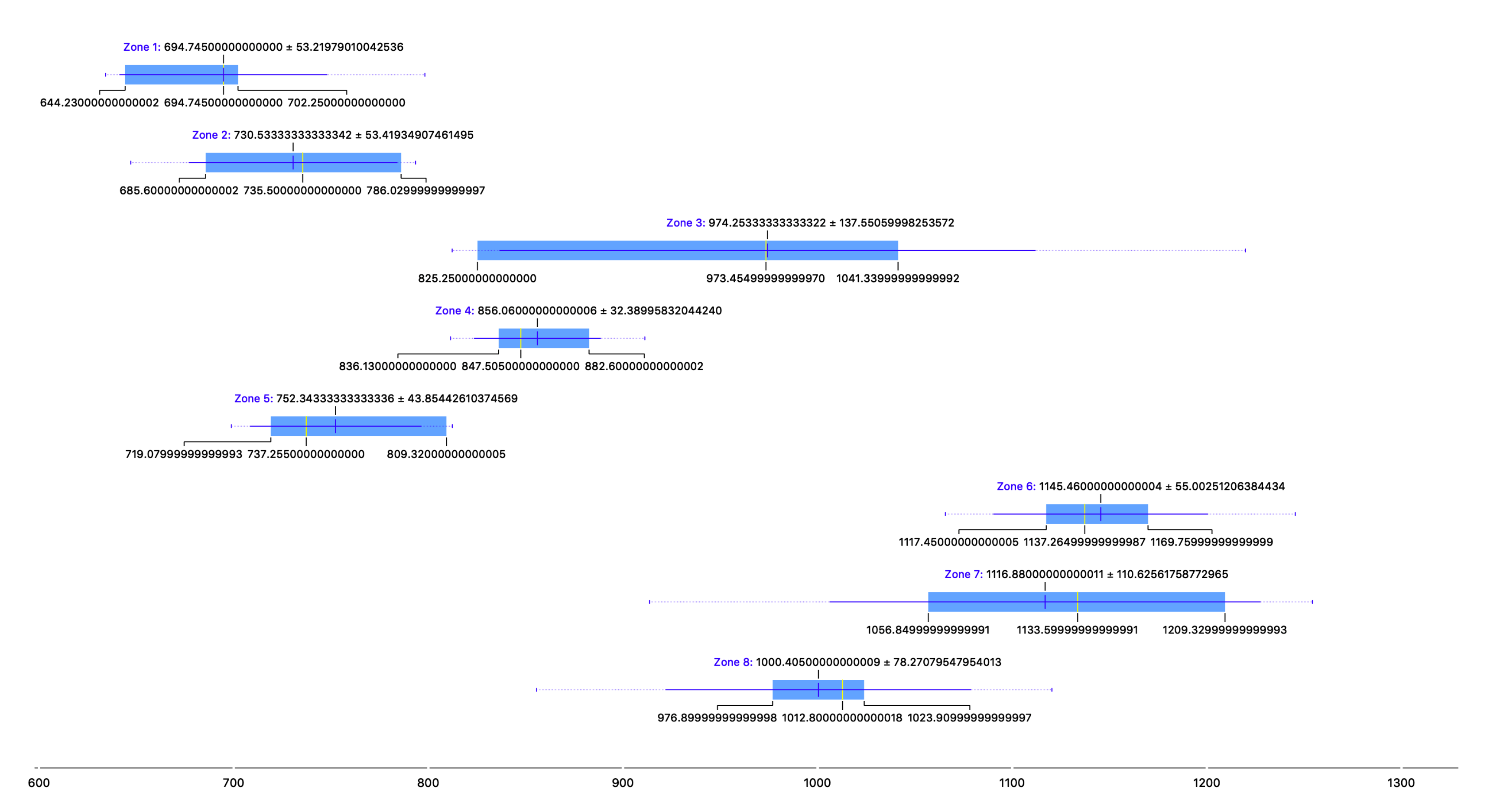
SUMMARY OF MEASUREMENTS IN THE SERRA GROSSA TUNNEL
ZonePlaceNumber of SamplesAverage Concentration Radon Gas (Bq/m 3 )
Zone 1100 m from the south entrance6694.75
Zone 2300 m from the south entrance6730.53
Zone 3500 m from the south entrance6974.25
Zone 4600 m from the south entrance6856.06
Zone 5700 m emergency exit6752.34
Zone 6800 m from the south entrance61145.46
Zone 71300 m from the south entrance61116.88
Zone 81400 m from south entrance61000.40

