Article

Stability Analysis of Surrounding Rock in Paste Backfill Recovery of Residual Room Pillars

1
State Key Laboratory of Coal Resources and Safe Mining, Xuzhou 221116, China
2
School of Minerals and Energy Resources Engineering, University of New South Wales, Sydney 2052, Australia
*
Author to whom correspondence should be addressed.
Sustainability 2019, 11(2), 478; https://doi.org/10.3390/su11020478
Submission received: 19 December 2018 / Revised: 8 January 2019 / Accepted: 14 January 2019 / Published: 17 January 2019
(This article belongs to the Section Energy Sustainability)

Abstract

:
A method of paste backfill recovery for residual room coal pillars is hereby proposed. The principles and processes of this method are systemically explained to address issues such as mining-induced earthquakes from spontaneous destabilization, surface subsidence, and low recovery rates. These are caused by the instability of residual coal pillars due to their spontaneous combustion in room-and-pillar mining in medium-to-small coalmines in the northern Shaanxi area. This method is based on the local abundance of surface aeolian sand and solid wastes to be used as paste-backfilling materials in coalmines in the northern Shaanxi area. Uniaxial compressive strength, bleeding rate, and slump tests were performed on paste-backfilled samples constituted at different ratios based on the types of materials involved in paste backfilling in the northern Shaanxi region, thereby helping to confirm the optimal ratios for paste-backfilling materials for the Ershike coal mine. A simulation was conducted to investigate the failure, goaf vertical stress distribution, and surface deformation properties of paste-backfilled pillars and coal pillars, where paste backfilling was used with paste-backfilling materials constituted at different compressive strengths. This was to verify the experimental results that would be obtained with paste-backfilling materials constituted at different ratios, and reveal the mechanism by which paste backfilling of residual room pillars can maintain the mine’s surrounding rock stability. These study results are of great instructive significance to the safe recovery of residual room pillars in China’s western mining areas.

1. Introduction

The coal resources of the Jurassic coalfield in northern Shaanxi, China, are widely distributed across the Yulin area. With excellent occurrence, simple structure, and high quality, they are reputed by experts as “environmental coal”, and are high-quality coal resources for power, liquefaction, and the chemical industry, which are rarely found inside or outside China [1,2,3]. However, as in the past, this area has featured quite a large number of medium-to-small-scale mines. Most of the coalmines have adopted room or room-and-pillar mining, given various economic, technical, and equipment limitations, with recovery rates under 30%. This has led to significant quantities of high-quality coal resources being left in the mines and becoming idle. According to incomplete statistics, there are as many as seven billion tons of resources contained in the residual room mining pillars in Ordos City, Inner Mongolia, and more than two billion tons in the residual room mining pillars in Shenmu County, Yulin City, Shaanxi Province [4,5,6,7]. This has not only created mining losses of coal resources, but the residual coal pillars are also highly prone to destabilization failure under the effect of long-term load, leading to severe mining catastrophes such as large-area roof collapses, and even mining-induced earthquakes. Therefore, the problem of how to recover residual room pillar resources safely has become a major issue [8,9,10].
Considerable research has been undertaken by scholars in China and other countries regarding the recovery of residual room mining pillar resources. Singh et al. [11] carried out an analysis of the state of coal pillar recovery in India, studying the impact factors on the stability of deep-seated room-and-pillar mine pillars under the condition of high stress; Gan et al. [6] examined the prudent allocation of mining gateways underneath room-and-pillar goafs; Ghasemi et al. [5] proposed a new coal pillar design method to reduce support stress concentration and coal pillar sizes; Haibo et al. [12] studied roof stress on room mining residual pillars and analyzed the critical factors influencing roof stability; Jixiong et al. [13,14] analyzed the impact pattern of compression ratio on coal pillar stability, establishing a mechanical model for solid-filled recovery room pillars, and designed a corresponding coal pillar recovery process; Yun et al. [14] investigated the safe recovery of residual room pillars below an aquifer, proposed a method of short wall block mining, and established a water-conducting fracture zone development height model based on this method. According to the above studies, at present, the recovery of residual room mining pillars mainly involves the methods of solid-filled mining, short wall block mining, and other measures. Although these methods may be applicable to some coal mines in the northern Shaanxi region with certain modifications and improvements, for most coal mines they can hardly accommodate the actual technical conditions and the geological factors of mining. Therefore, developing a more suitable recovery measure of residual room pillars is an urgent issue [15]. The ground surface in northern Shaanxi’s mining area is covered with considerable natural aeolian sand, which is an excellent paste-backfilling material, and the cemented paste backfill (CPB) technology for coal mining is currently a major direction of green mining. It can not only achieve the recovery of residual room pillar resources, but also dispose of surface aeolian sands, fly ash, and other solid wastes, and has become the first choice for the recovery of residual room coal pillar resources, the control of surface subsidence, and the protection of the ecological environment in the northern Shaanxi region [16,17,18,19,20,21,22].
This paper proposes the principles and processes for the use of paste backfilling to recover residual room coal resources, and shows the tests performed to optimize the ratios at which paste-backfilling materials are constituted, while shedding further light on the stability of the surrounding rock in the stope of residual room coal pillar recovery by paste backfilling under the engineering backdrop of the residual room pillar recovery at the Ershike coal mine. This paper has major instructive significance pertaining to the safe recovery of room mining residual pillars in mine areas in western China.

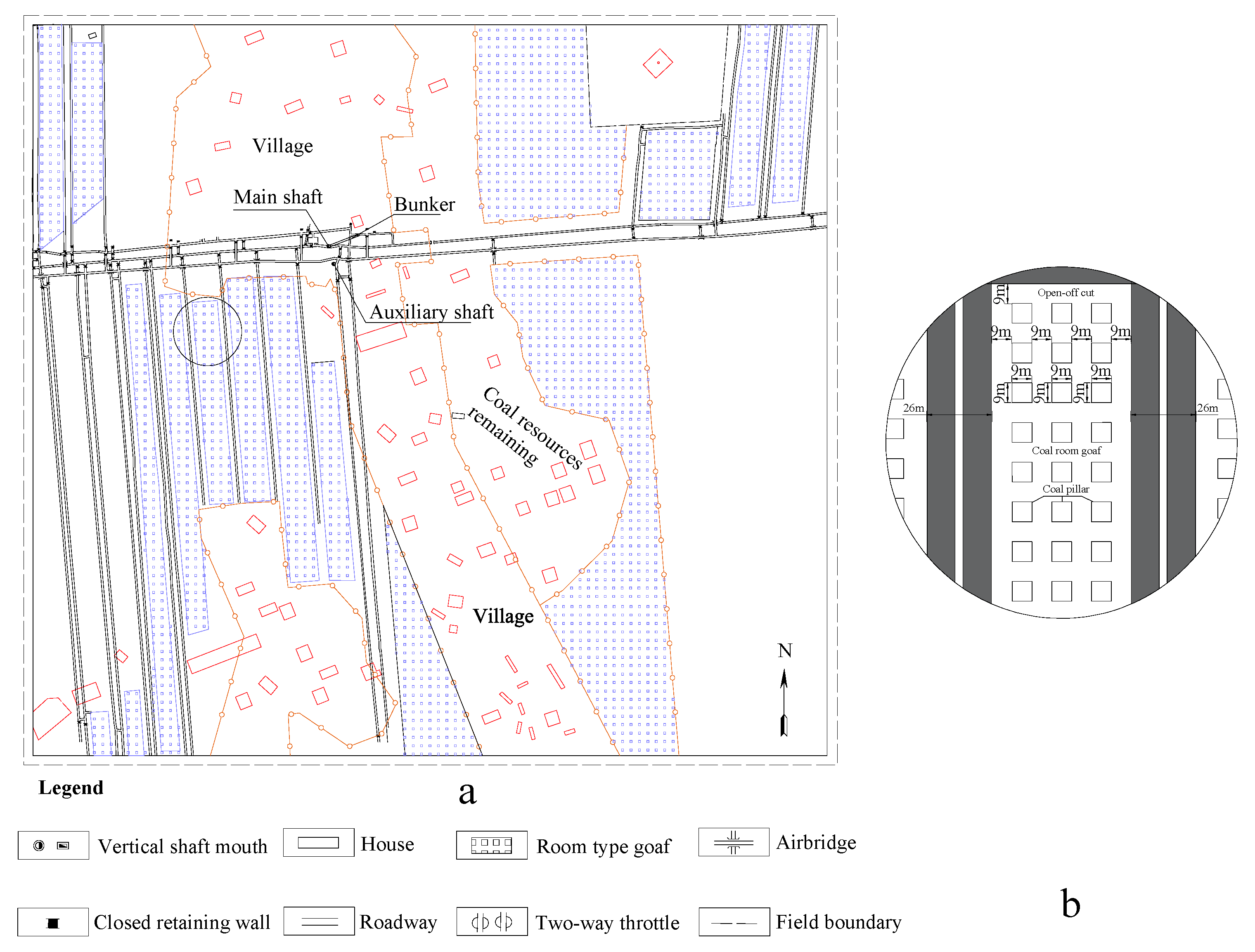
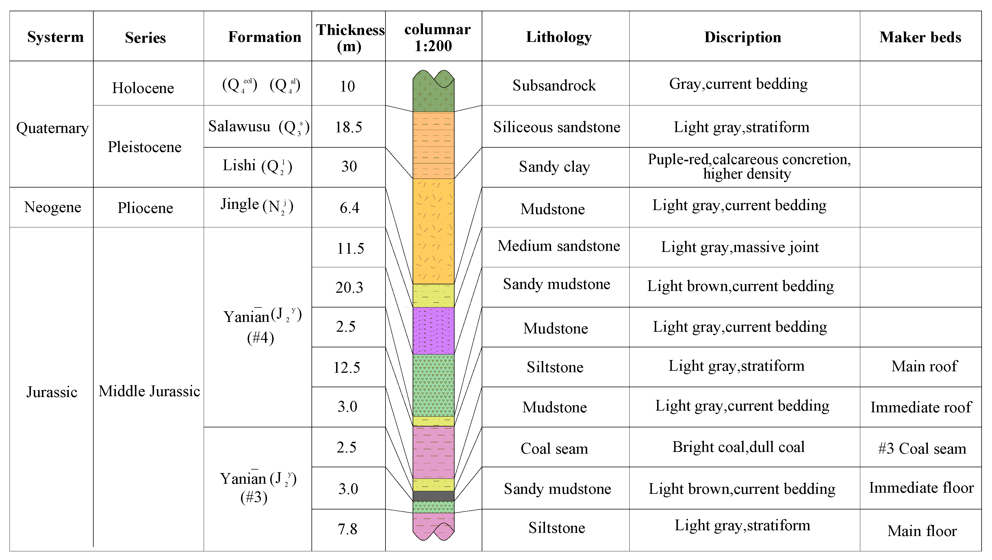
2. Overview of the Study Area

The Ershike coal mine is located in Hengshan County, Yulin City, Shaanxi Province, at the southern edge of the Maowusu Desert, at a distance of 33 km from the city. The minefield is located in the Mesozoic northern Ordos basin, and forms a regular quadrilateral, with a length of approximately 1.9 km, width of approximately 1.6 km, area of 3.04 km2, and recoverable reserves of 4.34 Mt. The stratum, a coal bed with a simple structure, is a monoclonal stratum inclined to the southwest at an inclination angle of around 1°, and lacks large fractures and folds. Coal seam No. 3, the primary mineable seam of the minefield, is a stable medium-thick coal seam that is mineable across the whole area, and has an average thickness of 2.5 m. The coal seam has a buried depth of 115–125 m.
The minefield currently employs the method of room-and-pillar mining, which involves mining the coal seam with a blasting mining process. The depth of the explosive hole is 1.5 m, and ammonium nitrate explosives are used. The recovery rate of the coal resources is under 40%, and the application of room-and-pillar mining has led to large quantities of high-quality coal resources remaining in the goaf. Moreover, as shown in Figure 1 (insert b is the local magnification of the working face in insert a), there are three columns of residual coal pillars on the working face. The pillar-to-room width is consistently 9 m. The safety factor of the residual coal pillars is 1.25, while the generally accepted critical value for the safety factor is 1.5. Moreover, based on the engineering practice studies of room-and-pillar mining under similar conditions [23,24], the failing and unstable coal pillars account for 50% of the coal pillar group which has width-to-height ratio of 3.6 in the Ershike coal mine due to loading. Furthermore, the phenomenon of stress concentration is prevalent at the corners of the coal pillars. Within the minefield, there are Quaternary sandy-porous phreatic aquifer, Middle Jurassic Zhiluo Formation sandstone aquifer, as well as a Middle-Lower Jurassic Yan’an Formation fissured aquifer layer. The aquifuge layers are siltstone and mudstone between the aquifer layers. There is no water contact between the aquifer layers. The mine field drill hole histogram is shown in Figure 2. The question of how to recover room residual pillars safely and efficiently has become a major issue facing the Ershike coal mine.

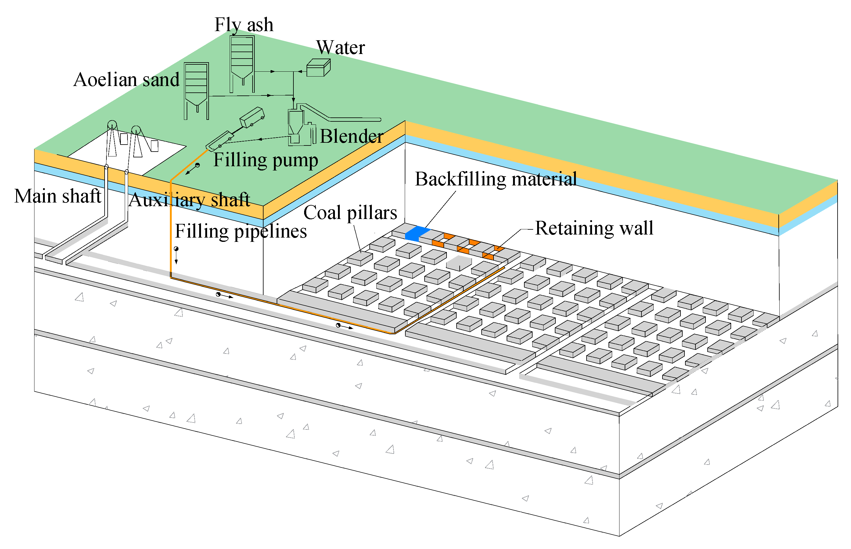
3. Paste Backfill Recovery Method for Residual Room Pillars

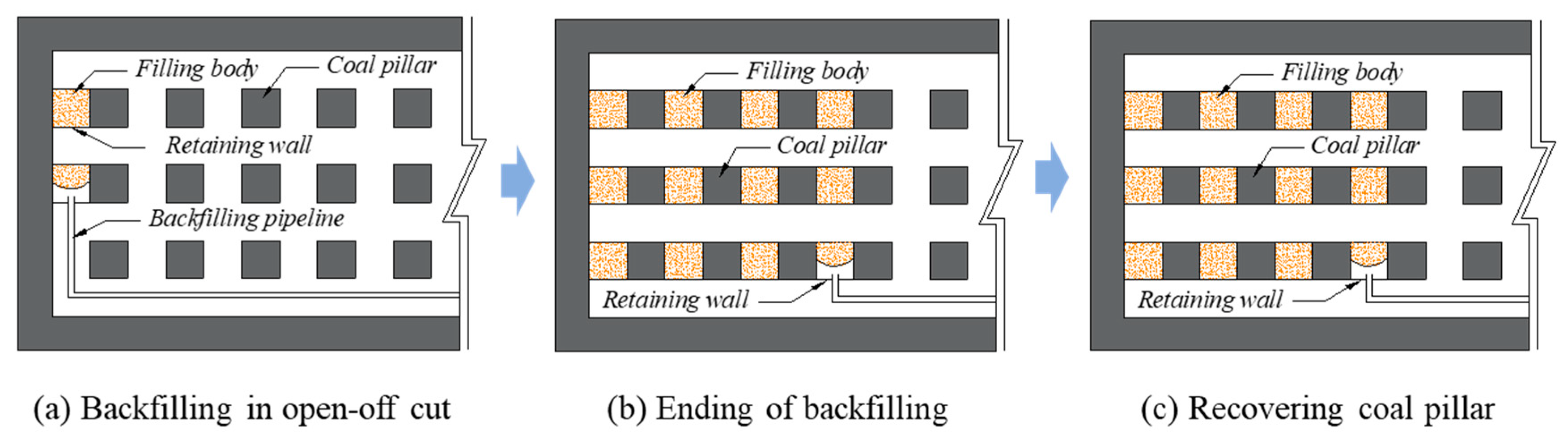
3.1. Principles Underlying Paste Backfill Recovery of Residual Room Pillars

In essence, paste backfill recovery of residual room pillars is the utilization of the supporting strength of a paste-backfilled structure in place of the supporting strength of the residual coal pillars, thereby achieving the recovery of the residual coal pillars [25,26,27], the CPB system is shown in Figure 3. The paste-backfilling material is mixed and processed according to the optimal ratio of surface aeolian sand, fly ash, and other filling materials that have been determined by laboratory tests. These materials are transported through filling pipelines to the room mining goaf for backfilling. Because the paste-backfilled structure can support the load of overburden rock, it effectively shares the residual coal pillars’ supporting strength and is thereby able to achieve the recovery of the room residual pillars.

3.2. Process for Paste Backfill Recovery of Residual Room Pillars

The process proposed herein for paste-backfill recovery of residual room coal pillars based on the technical properties associated with paste backfilling and parameters such as solidification time and the mine’s periodic weighting pace is as follows: starting from the distal boundary of the working face, use the construction of a backfilling retaining wall between two adjacent room coal pillars (the backfilling retaining wall is prepared by immobilizing the backfilling bag made of rubber between the two coal pillars and the paste-backfilling materials are transported to the backfilling bag through the backfilling pipelines; the paste-backfilling materials are prepared according to the optimal ratio determined by laboratory tests) to form a closed area with dimensions of 9 × 9 × 2.5 m. Then, we use the backfilling pipeline to transport the paste-backfilling material to the closed area to form paste-backfilling columns supporting the roof, as shown in Figure 4a. With three backfilled pillars forming one row, four rows of backfilled pillars are formed in the working face direction, as shown in Figure 4b. Following the working direction starting from the distal boundary of the working face and advancing toward the working face, three rows of residual coal pillars are recovered in sequence using the blasting mining. The coal is then loaded onto a loader and transported with a trackless rubber-tyred vehicle until the recovery of all three rows of residual coal pillars is complete. At this point, one fill-recover cycle is completed, as shown in Figure 4c. Recovery of the residual coal pillars of the entire room mining goaf is achieved in the same manner. For each cycle, the time needed for the recovery of three rows of coal pillars is nine days, and it takes three days to finish the backfilling (the first cycle lasts for four days).

4. Selection and Optimization of Paste-Backfilling Materials

4.1. Selection of Paste-Backfilling Materials

The Ershike coal mine is located at the border of the Maowusu Desert in northern Shaanxi and the Huangtu Plateau. Its surface is covered by large quantities of natural aeolian sand, which is resistant to weathering, hydrolysis, and stress concentration, and can transmit and carry pressure quite well due to the fineness and uniformity of its particles. Therefore, aeolian sand is an ideal paste-backfilling material. Furthermore, power plants near the mine can provide fly ash, which can also be used as a paste-backfilling material [28,29,30]. With comprehensive consideration of the backfilling costs, quality, and other factors involved in CPB, the materials to be prepared for this mine’s paste-backfilled structure are determined as aeolian sand, power plant fly ash, cement, and quicklime.

4.2. Optimizing the Ratio of Paste-Backfilling Materials

This paper incorporates different designs for paste-backfilling materials at varying ratios to help select a suitable ratio of paste-backfilling materials and guarantee the strength and effects of backfilling, with a total of nine experimental plans proposed with the ratios shown in Table 1. In accordance with these experimental plans, the samples were prepared based on each plan’s ratios for paste-backfilled structures with dimensions of 0.0707 × 0.0707 × 0.0707 m and with 28-day-aged standard curing. Uniaxial compressive strength, bleeding rate, and slump tests were carried out on the samples under each plan, with the testing results shown in Table 2.
According to the test results obtained, the higher the quicklime, fly ash, and cement contents, the higher is the strength of the paste-backfilled structure and the lower is the bleeding and slump rates. With a comprehensive consideration of the costs of backfilling materials, plan A9 was finally confirmed as the right paste-backfilling material ratio for the Ershike coal mine.

5. Stability Analysis of Surrounding Rock of the Stope under Recovery of Residual Coal Pillars

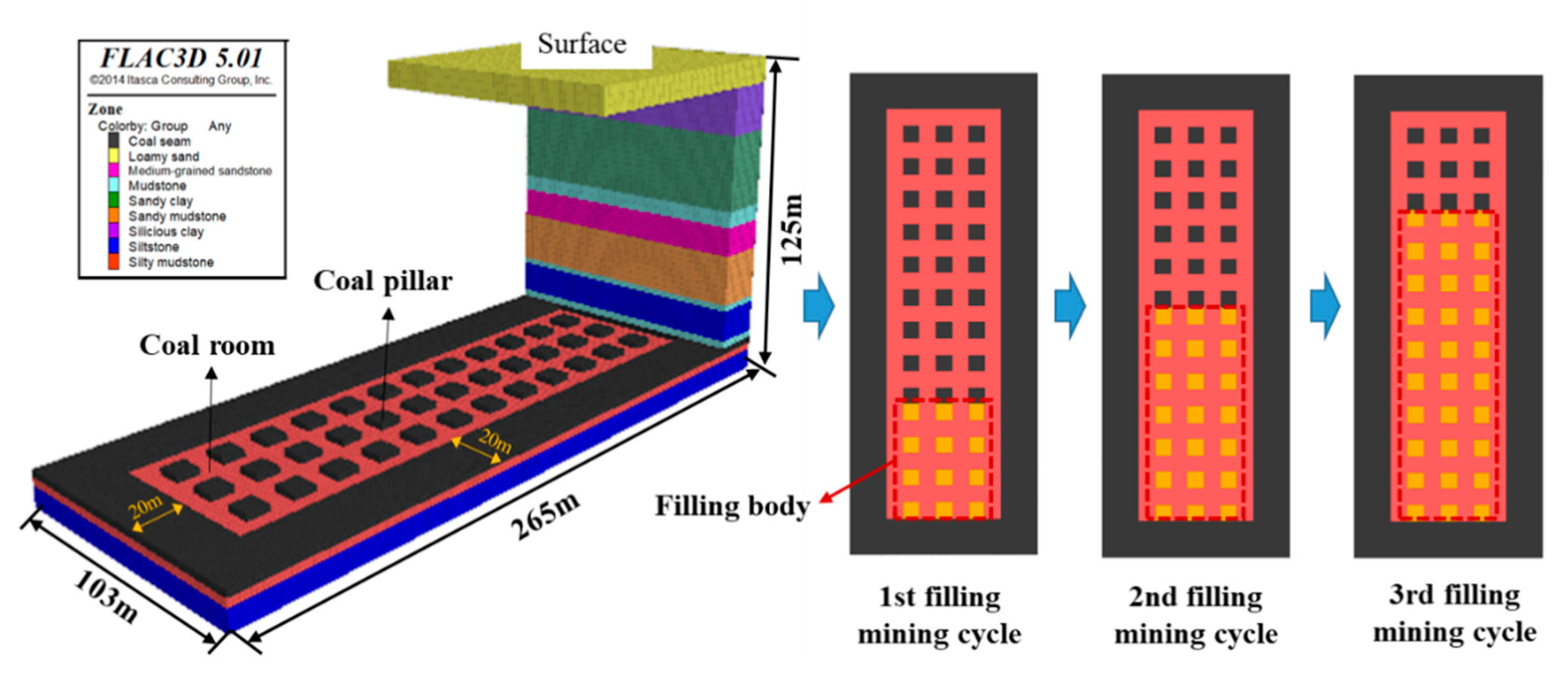
5.1. Building a Numerical Model

To verify the rationality of the ratio of paste-backfilling materials outlined in Section 4, and to reveal more about the stability of the surrounding rock of the stope under a paste-backfill recovery of residual room pillars, a numerical model with geometric dimensions of 265 × 103 × 121 m was established. This was based on the geological mining conditions pertaining to the Ershike coal mine. Horizontal displacement was constrained at the model’s surrounding boundary, vertical displacement was constrained at the lower boundary, while the upper boundary was free. The Mohr–Coulomb principle was employed for the yield criterion of the rock strata, with the physical and mechanical parameters of each stratum sourced from mine drilling data, as shown in Table 3. Protective coal pillars 20 m in width were, respectively, placed at the surrounding boundary to eliminate the impact of the boundary effect, and coal pillars in three columns and 12 rows at a volume of 9 × 9 × 2.5 m were formed by excavating a coal room with a width of 9 m. The model was then used to simulate and study the failure, stope vertical stress distribution, and surface deformation properties of the paste-backfilled pillars and coal pillars when one fill-recovery cycle (advancing 54 m), two fill-recovery cycles (advancing 108 m), and three fill-recovery cycles (advancing 162 m) were completed at the working face using backfilling materials of compressive strengths of 1, 2, or 3 MPa. The physical and mechanical parameters of the filling materials under different compressive strengths are shown in Table 4. The numerical model is shown in Figure 5.

5.2. Results and Analysis

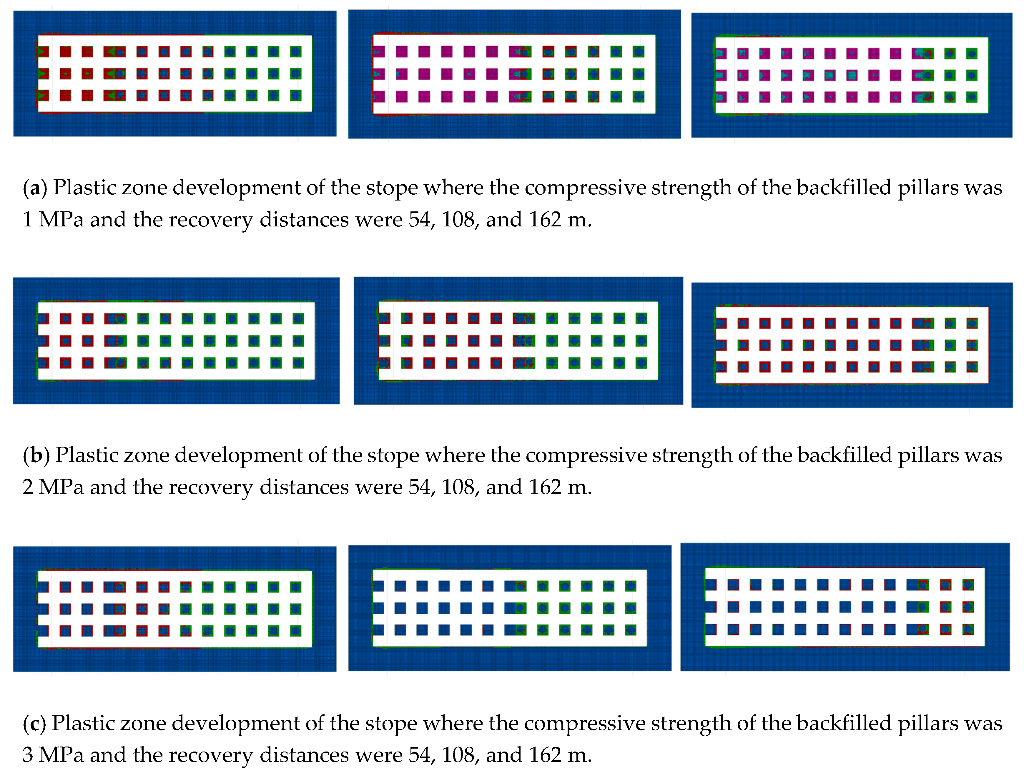
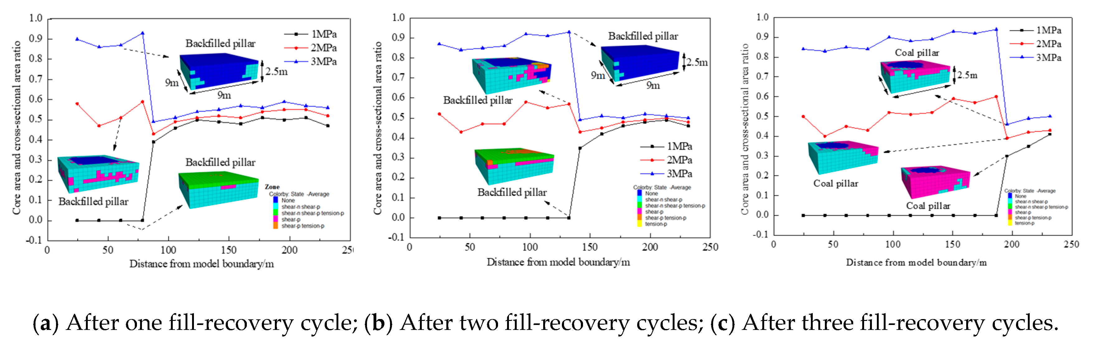
5.2.1 Paste-Backfilled Pillar and Coal Pillar Failure Properties

The changing plastic zone development properties in the backfilled pillars and coal pillars with changing recovery distances of the working face at the backfilled pillars’ compressive strengths of 1, 2, and 3 MPa are highlighted in Figure 6. The greater the compressive strengths of the backfilled pillars, the lower is the degree of damage to the backfilled and coal pillars.
A backfilled pillar-coal pillar row in the center of the working face was selected, and the ratio of the elastic core area to the cross-sectional area (hereafter core-area ratio) for each backfilled pillar and coal pillar’s interstitial cross-section was extracted. Furthermore, the differing compressive strengths of the backfilled pillars and core-area ratios under varying recovery distances were obtained, as shown in Figure 7.
Figure 6 and Figure 7 show that:
(1) There was a significant increase in the core-area ratios for backfilled pillars as the compressive strengths of the backfilled pillars were sequentially changed from 1 MPa to 2 MPa and then to 3 MPa, and these were located within three typical threshold intervals. There was a minor increase in the core-area ratios of the coal pillars in the 0.4−0.6 range.
(2) The core-area ratios of the backfilled pillars located at the very front and very back of the fill-recovery working face were relatively large when the compressive strengths of the backfilled pillars were 2 and 3 MPa. The plastic zone of the first row of the coal pillars at the front of the fill-recovery working face was quite developed compared to the other coal pillars. Moreover, there was a trend that coal pillars at greater distance from the fill-recovery working face had greater core-area ratios.
(3) All values of the core-area ratio of the backfilled pillars were 0 when the compressive strengths of the backfilled pillars were 1 MPa, showing that the backfilled pillars experienced general plastic failure. The rate for the core-area ratios of the backfilled pillars was basically less than 0.5 when their compressive strength was 2 MPa, showing that the backfilled pillars experienced partial plastic failure. The core-area ratios of the backfilled pillars when the compressive strengths of the backfilled pillars were 3 MPa were all greater than 0.8, showing that the backfilled pillars experienced local plastic failure, but still had excellent stability.

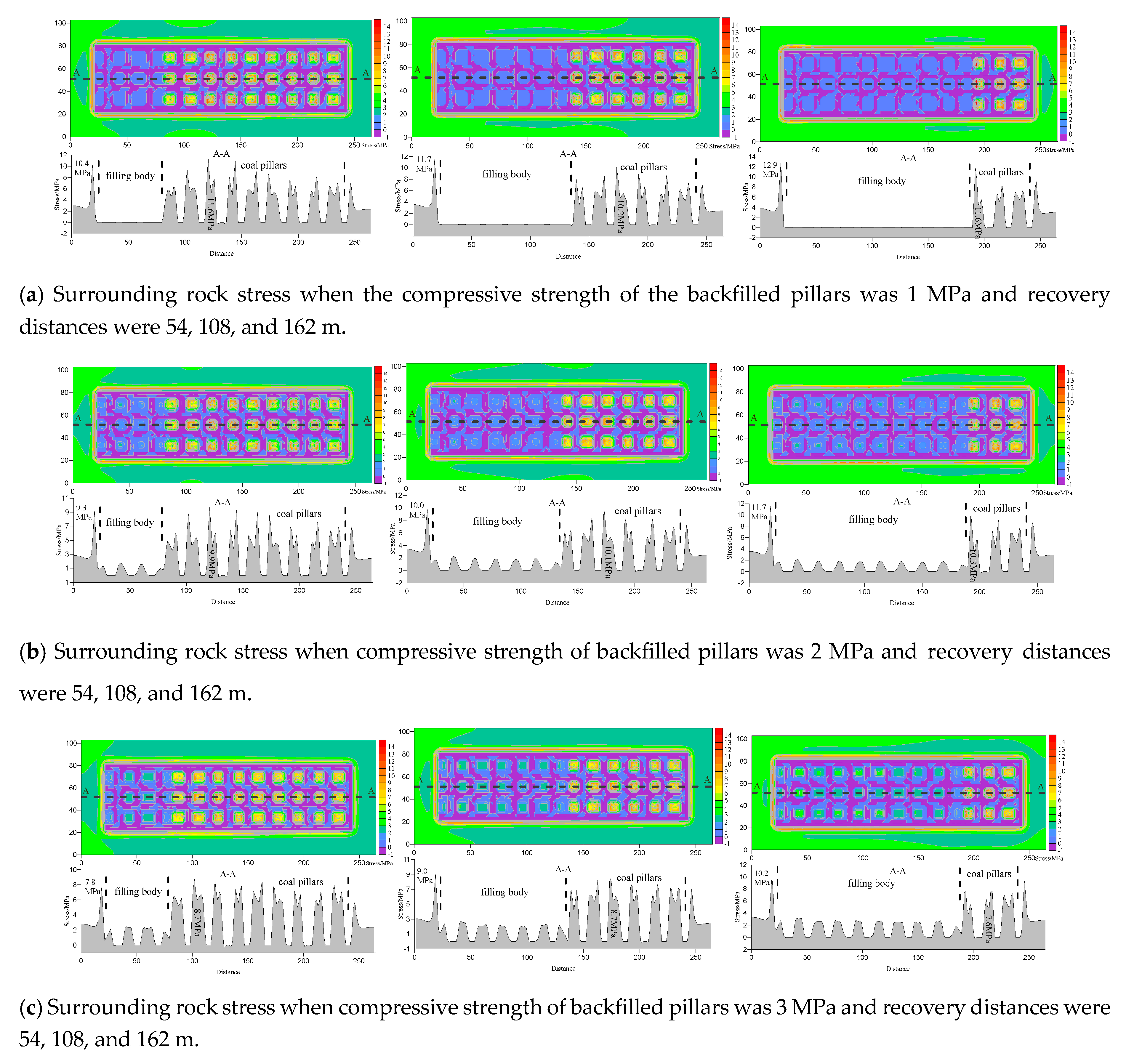
5.2.2. Vertical Stress Distribution Properties of the Stope

Figure 8 shows the changing vertical stress properties of the stope’s surrounding rocks along with changes in the working face recovery distance when the compressive strengths of the backfilled pillars were 1, 2, or 3 MPa.
Figure 8 shows that the stress experienced by the backfilled pillars was 0 when the compressive strength of the backfilled pillars was 1 MPa, showing destabilization failure; the distribution pattern for vertical stress on the backfilled pillars presented a “pointy wave-like peak” when the compressive strength of the backfilled pillars was 2 MPa, showing that the backfilled structure was in an unstable state; the distribution pattern for vertical stress on the backfilled pillars presented a “central platform” when the compressive strength was 3 MPa, and this state did not change with increased fill-recovery working face distance, showing that the backfilled pillar possessed good stability. The stope’s stress distribution properties put greater stress on coal pillars in central locations and less stress on those at ends when the compressive strengths of the backfilled pillars were 1 and 2 MPa and the fill-recovery working face was recovering in the first and second fill-recovery cycles. However, there was a clear increase in stress on the first row of coal pillars at the front of the working face when recovery reached the third fill-recovery cycle, and its stress distribution pattern gradually evolved toward a “single peak”, showing a tendency toward gradual destabilization failure. Stress distribution over the stope constantly presented greater stress on centrally located coal pillars and less stress on coal pillars at ends when the compressive strength of the backfilled pillars was 3 MPa. Moreover, the stress distribution pattern for each coal pillar was in a “ringed peak type”, showing that the coal pillars possessed good stability.

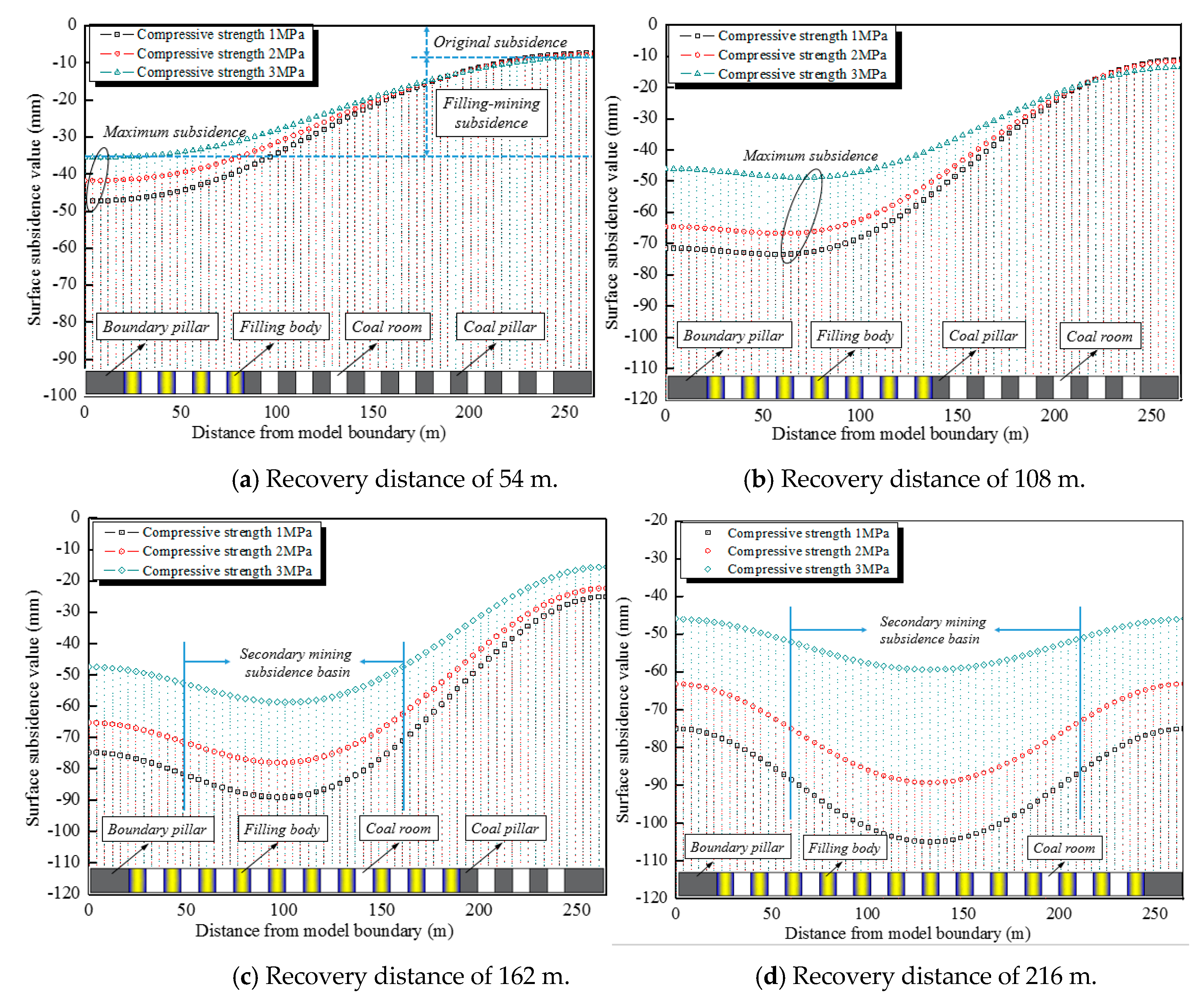
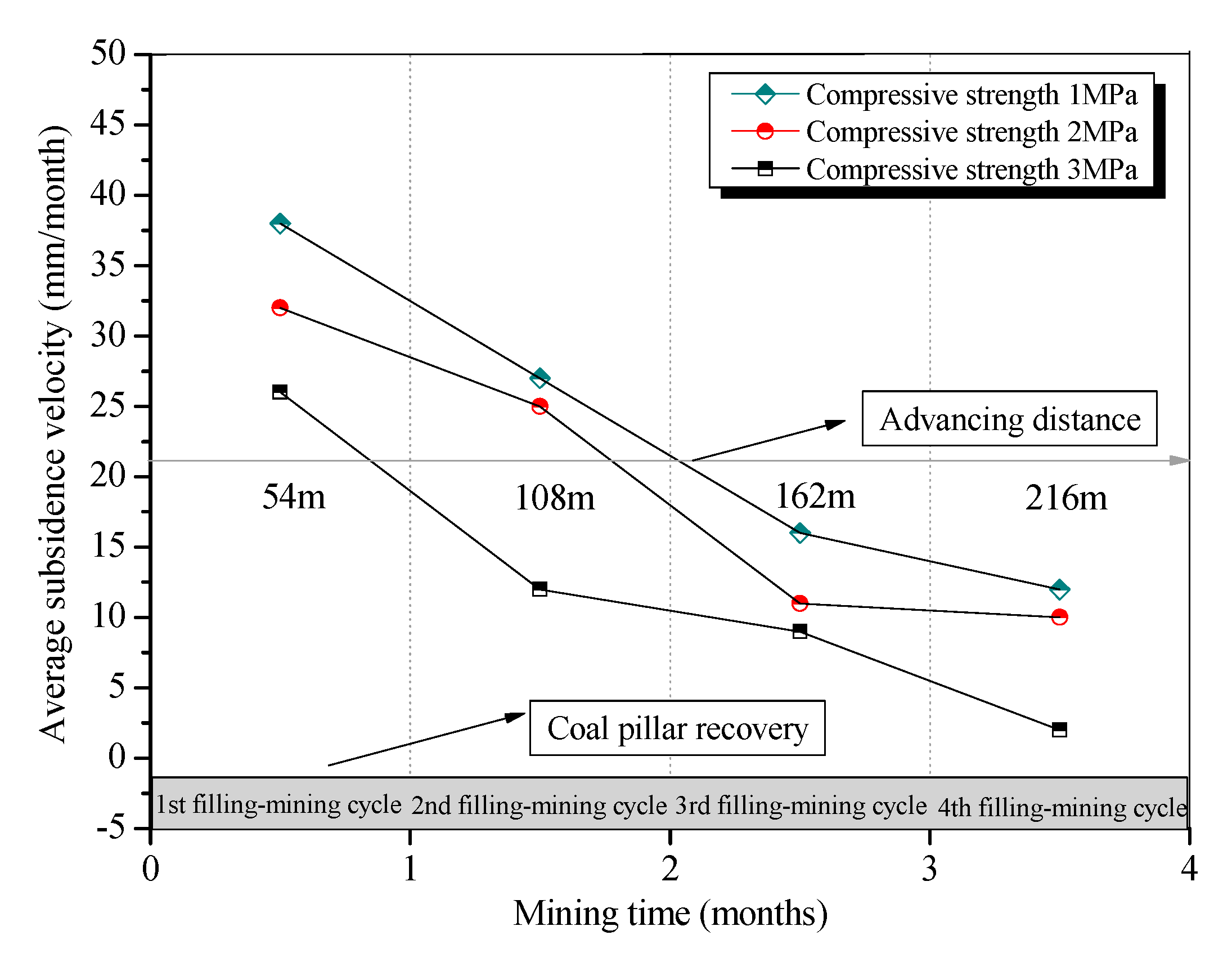
5.2.3. Surface Deformation Characteristics

Figure 9 shows changing surface subsidence properties above the working face alongside the changing recovery distances where the compressive strengths of the backfilled pillars were 1, 2, and 3 MPa.
To investigate the average surface subsidence rates with backfilled pillars of different compressive strengths, and based on the simulation results shown in Figure 9, the ratio between the variation in the maximum surface subsidence values of two before and after fill-recovery cycles and the length of time required for one fill-recovery cycle were calculated together to forecast a period of 30 days. This was necessary for the completion of one fill-recovery cycle in this fill-recovery plan and based on relevant fill-recovery engineering experience. Changing properties of the average surface subsidence rates were plotted accordingly, as shown in Figure 10.
(1) Figure 9a shows that the ground surface in the area on the right side of the model boundary tends to be horizontal when the working face is recovered to be 54 m, with no obvious subsidence deformations, showing that it is yet to be impacted by the fill-recovery working face mining. The surface subsidence value at this time is the original surface subsidence value caused by room and pillar mining (10 mm). Additionally, the maximum surface subsidence value at this time is found at the model’s boundary behind the fill-recovery working face, and its value is the sum of the surface’s original subsidence value and fill-recovery subsidence value.
(2) Figure 9b−d show that there is a progressive increase in maximum surface subsidence values under different backfilled column compressive strengths when the fill-recovery working face is recovered to 108, 162, and 216 m, and there is a gradual shift in subsidence peak values toward the working face direction, which also gradually tends toward the center of the goaf. When the working face is recovered to 162 m, maximum surface inclinations of 0.37 mm/m, 0.49 mm/m, and 0.63 mm/m are reached under the backfilled column compressive strength of 1, 2, and 3 MP, respectively. Furthermore, a secondary subsidence basin appears on the surface above the goaf under the impact of residual coal pillar fill-recovery mining activities when the fill-recovery working face is recovered to 162 and 216 m.
(3) Figure 9 and Figure 10 show that the maximum surface subsidence values and average subsidence rates decrease with an increase in the backfilled pillars’ compressive strengths. As the working face recovery reaches 216 m, when the backfilled pillars’ compressive strengths are 1, 2, and 3 MPa, the corresponding maximum surface subsidence values are 104, 89, and 58 mm, respectively, and their corresponding subsidence coefficients are 0.043, 0.037, and 0.024. Furthermore, the average surface subsidence rates at this moment are 13, 11, and 2 mm/month, respectively. This indicates that when the backfilled pillars’ compressive strengths are 1 MPa and 2 MPa, and when the fill-recovery working face is still advancing, the surface would continue to experience subsidence. However, the surface would approach a full mining state without further subsidence when the backfilled pillars’ compressive strength is 3 MPa.
In summary, paste-backfilled pillars during the residual pillar recovery process can not only reduce coal pillar failure and prevent stress concentration, but may also help to control surface subsidence. The controlling effects of the paste-backfilled pillars are improved with greater compressive strength of the backfilled pillars. As regards the specific working conditions of the Ershike coal mine, backfilled pillars with a compressive strength of 3 MPa are entirely capable of satisfying the safety requirements as regards residual room pillar recovery.

6. Conclusions

(1) A method of paste backfilling to help recover residual room coal pillars is proposed; the principles underlying the paste backfill recovery of residual room coal pillars are explained; and the paste-backfill recovery processes for residual room coal pillars are provided.
(2) Uniaxial compressive strength, bleeding rate, and slump tests are carried out on paste-backfilling materials at different ratios to optimize the ratio of backfilling materials. Furthermore, plan A9 (47.5% fly ash + 39.5% aeolian sand + 8% cement + 5% quicklime) is finally decided upon as the right ratio of paste-backfilling materials for the Ershike coal mine.
(3) Modeling is used to simulate and study the failure, stope vertical stress distribution, and surface deformation properties of paste-backfilled pillars and coal pillars when paste-backfilling materials are constituted at different compressive strengths and advanced to different distances, verifying the results of the ratio of backfilling materials and shedding more light on the ways in which paste backfilling helps to maintain the stability of the stope’s surrounding rock throughout the residual room pillar recovery process.

Author Contributions

Conceptualization, N.Z.; Methodology, H.Y. and S.J.; Numerical model, N.Z. and Q.S.; Resources, S.O.; Data Curation, H.Y. and S.O.; Writing-Original Draft Preparation, S.J.

Acknowledgments

This research was supported by the Fundamental Research Funds for the Central Universities, grant number 2017XKZD13. The authors gratefully acknowledge the financial support of the abovementioned organization.

Conflicts of Interest

The authors declare no conflict of interest.

References

  1. Li, X.; Xue, Y.; Feng, J.; Yi, Q.; Li, W.; Guo, X.; Liu, K. Co-pyrolysis of lignite and Shendong coal direct liquefaction residue. Fuel 2015, 144, 342–348. [Google Scholar] [CrossRef]
  2. Zhang, D.; Fan, G.; Ma, L.; Wang, X. Aquifer protection during longwall mining of shallow coal seams: A case study in the Shendong Coalfield of China. Int. J. Coal Geol. 2011, 86, 190–196. [Google Scholar] [CrossRef]
  3. Zhang, Y.; Wu, J.; Chang, L.; Wang, J.; Xue, S.; Li, Z. Kinetic and thermodynamic studies on the mechanism of low-temperature oxidation of coal: A case study of Shendong coal (China). Int. J. Coal Geol. 2013, 120, 41–49. [Google Scholar] [CrossRef]
  4. Chen, Y.; Ma, S.; Cao, Q. Extraction of the remnant coal pillar in regular and irregular shapes: A case study. J. Loss Prev. Process Ind. 2018, 55, 191–203. [Google Scholar] [CrossRef]
  5. Ghasemi, E.; Shahriar, K. A new coal pillars design method in order to enhance safety of the retreat mining in room and pillar mines. Saf. Sci. 2012, 50, 579–585. [Google Scholar] [CrossRef]
  6. Jin, G.; Wang, L.G.; Zhang, J.H.; Hu, M.J.; Duan, N. Roadway layout for recycling residual coal pillar in room-and-pillar mining of thick coal seam. Int. J. Min. Sci. Technol. 2015, 25, 729–734. [Google Scholar] [CrossRef]
  7. Zhou, N.; Li, M.; Zhang, J.; Gao, R. Roadway backfill method to prevent geohazards induced by room and pillar mining: A case study in Changxing coal mine, China. Nat. Hazards Earth Syst. Sci. 2016, 16, 2473–2484. [Google Scholar] [CrossRef]
  8. Zhou, Y.J.; Li, M.; Xu, X.D.; Li, X.T.; Ma, Y.D.; Ma, Z.G. Research on Catastrophic Pillar Instability in Room and Pillar Gypsum Mining. Sustainability 2018, 10, 3773. [Google Scholar] [CrossRef]
  9. Luan, H.J.; Lin, H.L.; Jiang, Y.J.; Wang, Y.H.; Liu, J.K.; Wang, P. Risks Induced by Room Mining Goaf and Their Assessment: A Case Study in the Shenfu-Dongsheng Mining Area. Sustainability 2018, 10, 631. [Google Scholar] [CrossRef]
  10. Sherizadeh, T.; Kulatilake, P.H.S.W. Assessment of roof stability in a room and pillar coal mine in the US using three-dimensional distinct element method. Tunn. Undergr. Space Technol. 2016, 59, 24–37. [Google Scholar] [CrossRef]
  11. Singh, R.; Mandal, P.K.; Singh, A.K.; Kumar, R.; Sinha, A. Coal pillar extraction at deep cover: With special reference to Indian coalfields. Int. J. Coal Geol. 2011, 86, 276–288. [Google Scholar] [CrossRef]
  12. Tang, H.B.; Liu, D.P.; Wang, S.Q. Roof Stress Analysis and Roof Pressure Observation in Residual Coal Mining after Room and Pillar Mining. Coal Technol. 2015, 34, 37–39. [Google Scholar]
  13. Zhang, J.X.; Huang, P.; Zhang, Q.; Li, M.; Chen, Z.W. Stability and control of room mining coal pillars-taking room mining coal pillars of solid backfill recovery as an example. J. Cent. South Univ. 2017, 24, 1121–1132. [Google Scholar] [CrossRef]
  14. Miao, X.X.; Zhang, J.X.; Guo, G.L. Study on waste-filling method and technology in fully-mechanized coal mining. J. China Coal Soc. 2010, 35, 1–6. [Google Scholar]
  15. Zhang, Y.; Cao, S.; Guo, S.; Wan, T.; Wang, J. Mechanisms of the development of water-conducting fracture zone in overlying strata during shortwall block backfill mining: A case study in Northwestern China. Environ. Earth Sci. 2018, 77, 543. [Google Scholar] [CrossRef]
  16. Deng, X.J.; Zhang, J.X.; Zhou, N.; Wit, B.D.; Wang, C.T. Upward slicing longwall-roadway cemented backfilling technology for mining an extra-thick coal seam located under aquifers: A case study. Environ. Earth Sci. 2017, 76, 789. [Google Scholar] [CrossRef]
  17. Guo, W.; Wang, H.; Chen, S. Coal pillar safety and surface deformation characteristics of wide strip pillar mining in deep mine. Arab. J. Geosci. 2016, 9, 1–9. [Google Scholar] [CrossRef]
  18. Sun, Q.; Zhang, X.D.; Yang, Y. Creep constitutive model of cemented body used in backfilling mining. J. China Coal Soc. 2013, 38, 994–1000. [Google Scholar]
  19. Wu, D.; Deng, T.F.; Zhao, P.K. A coupled THMC modeling application of cemented coal gangue-fly ash backfill. Constr. Build. Mater. 2018, 158, 326–336. [Google Scholar] [CrossRef]
  20. Yilmaz, T.; Ercikdi, B.; Deveci, H. Utilisation of construction and demolition waste as cemented paste backfill material for underground mine openings. J. Environ. Manag. 2018, 222, 250–259. [Google Scholar] [CrossRef]
  21. Deng, X.J.; Klein, B.; Zhang, J.X.; Hallbom, D.; Wit, B.D. Time-dependent rheological behaviour of cemented backfill mixture. Int. J. Min. Reclam. Environ. 2018, 32, 145–162. [Google Scholar] [CrossRef]
  22. Wu, D.; Yang, B.; Liu, Y. Transportability and pressure drop of fresh cemented coal gangue-fly ash backfill (CGFB) slurry in pipe loop. Powder Technol. 2015, 284, 218–224. [Google Scholar] [CrossRef]
  23. Xie, Q.Z. Study on Stability of Roof—Coal Pillar in Room and Pillar Mining Goaf in Shallow Depth Seam. Coal Sci. Technol. 2014, 42, 1–9. [Google Scholar]
  24. Deng, X.; Zhang, J.; Klein, B.; Zhou, N.; deWit, B. Experimental characterization of the influence of solid components on the rheological and mechanical properties of cemented paste backfill. Int. J. Miner. Process. 2017, 168, 116–125. [Google Scholar] [CrossRef]
  25. Ghirian, A.; Fall, M. Coupled thermo–hydro–mechanical–chemical behavior of cemented paste backfill in column experiments: Part II: mechanical, chemical and microstructural processes and characteristics. Eng. Geol. 2014, 170, 11–23. [Google Scholar] [CrossRef]
  26. Donovan, J.G.; Karfakis, M.G. Design of backfilled thin-seam coal pillars using earth pressure theory. Geotechn. Geol. Eng. 2004, 22, 627–642. [Google Scholar] [CrossRef]
  27. Qiang, S.; Zhang, J.; Nan, Z. Study and discussion of short- strip coal pillar recovery with cemented paste backfill. Int. J. Rock Mech. Min. Sci. 2018, 104, 147–155. [Google Scholar]
  28. Skrzypkowski, K. Compressibility of materials and backfilling mixtures with addition of solid wastes from flue-gas treatment and fly ashes. E3S Web Conf. 2018, 71. [Google Scholar] [CrossRef]
  29. Skrzypkowski, K.; Korzeniowski, W.; Poborska-Młynarska, K. Binding Capability of Ashes and Dusts from Municipal Solid Waste Incineration with Salt Brine and Geotechnical Parameters of the Cemented Samples. Arch. Min. Sci. 2018, 63, 903–918. [Google Scholar]
  30. Yan, H.; Zhang, J.X.; Zhou, N. Shaft failure characteristics and the control effects of backfill body compression ratio at ultra-contiguous coal seams mining. Environ. Earth Sci. 2018, 77, 458. [Google Scholar] [CrossRef]
Figure 1. (a) Working face layout. (b) Local magnification of working face.
Sustainability 11 00478 g001
Figure 2. Drill hole histogram.
Sustainability 11 00478 g002
Figure 3. Principles behind paste backfill recovery of residual room pillars.
Sustainability 11 00478 g003
Figure 4. Processes involved in the paste backfill recovery of residual room coal pillars.
Sustainability 11 00478 g004
Figure 5. Numerical calculation model.
Sustainability 11 00478 g005
Figure 6. Plastic zone development of the stope at different backfilled pillar compressive strengths.
Sustainability 11 00478 g006
Figure 7. Different compressive strengths for backfilled pillars and core-area ratios under different recovery distances.
Sustainability 11 00478 g007
Figure 8. Surrounding rock stress under different backfilled pillar compressive strengths and different recovery distances.
Sustainability 11 00478 g008
Figure 9. Surface subsidence values under different backfilled pillar compressive strengths and recovery distances.
Sustainability 11 00478 g009
Figure 10. Average subsidence rate of the ground surface.
Sustainability 11 00478 g010
Table 1. Paste-backfilling material-ratio plans.
No.Concentration (%)Fly Ash (%)Aeolian Sand (%)Cement (%)Quicklime (%)
A17247.544.580
A27247.539.585
A37247.534.5810
A47252.534.585
A57242.544.585
A67247.541.565
A77247.543.545
A87447.539.585
A97647.539.585
Table 2. Paste-backfilling material ratios test results.
No.28 d Strength (MPa)Bleeding Rate (%)Slump Rate (mm)
A11.7613.80220
A22.2312.07214
A31.9110.06210
A42.5510.54203
A52.2913.83199
A61.5611.67208
A71.1515.39215
A82.767.68201
A93.025.84178
Table 3. Physical and mechanical parameters for coal and rock strata.
No.Rock Stratum NameBulk Modulus (GPa)Shear Modulus (GPa)Tensile Strength (MPa)Cohesion (MPa)Internal Friction Angle (°)Density (kg/m3)
1Clayey silt0.080.050.050.116.01670.0
2Silica sand0.120.080.10.518.01800.0
3Sandy clay0.80.310.80.725.01600.0
4Mudstone0.60.320.80.627.01600.0
5Medium-grained sandstone1.601.141.02.332.02100.0
6Sandy mudstone0.630.500.61.028.02200.0
7Mudstone0.60.320.80.627.01600.0
8Siltstone1.871.121.02.030.02615.0
9Mudstone0.60.320.80.627.01600.0
10Coal seam0.800.411.860.325.01400.0
11Sandy mudstone0.630.500.61.028.02200.0
12Siltstone1.871.121.02.030.02615.0
Table 4. Physical and mechanical parameters of backfilled pillars.
Compressive Strength (MPa)Bulk Modulus (GPa)Shear Modulus (GPa)Tensile Strength (MPa)Cohesion (MPa)Internal Friction Angle (°)Density(kg/m3)
10.070.030.1450.2321.01670.0
20.090.040.1750.3124.01760.0
30.120.060.2110.5928.01736.0

