3. Calculation of the Incinerator Combustion Chambers Dimensions
For the waste composition presented by the Ministry of the Environment of Ontario, stoichiometric calculations were conducted for the assumed mass of waste equal to m = 50 kg and the duration of the combustion process of 3 h (
= 16.67 kg/h).
Table 2 presents an example of the percentage share of the individual components and their higher heating values in accordance with the Canadian assumptions [
22].
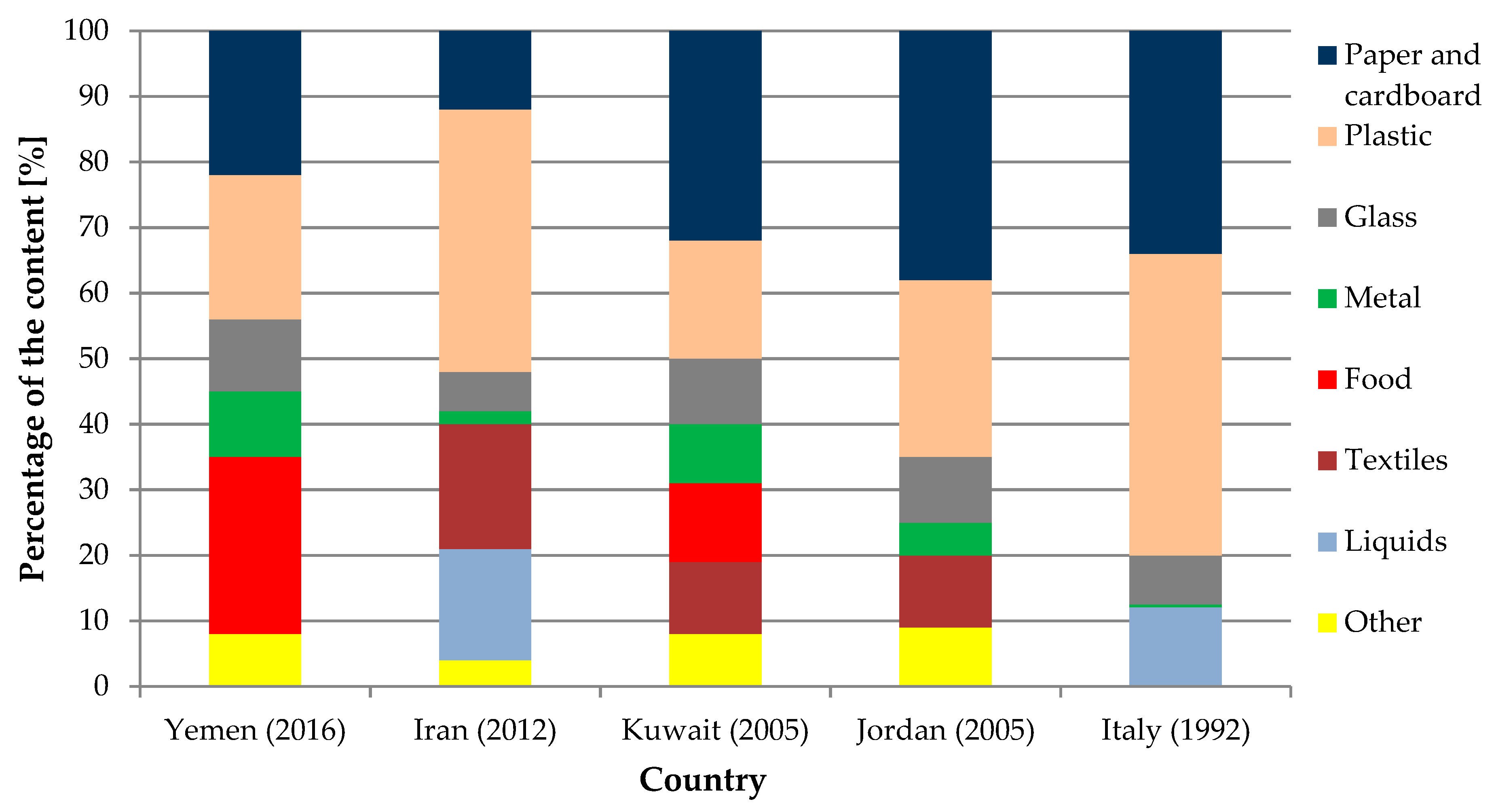
For comparison, calculations for the infectious medical waste were carried out with the composition presented in the research conducted in Isfahan (Iran) city [
14] in 2012 and in the studies carried out in the hospitals in southern Italy in 1992 [
15]. The composition considered in these studies is so precise that it is possible to make some additional assumptions and make stoichiometric calculations. The data exhibited a diversity of the waste compositions, revealing the spectrum of substances and their percentage. It is supposed that the waste coming from Poland are within this range. For the calculations, the guidelines of the Ministry of the Environment of Ontario [
22] were utilized. The technical assumptions, formulated by Ministry of the Environment of Ontario, are consistent with Polish law. All of its guidelines overlap with the requirements of Polish law, i.e., on the flue gas retention time and temperature. The assumptions on the temperature, air composition or latent heat of vaporization of water are also in-line with Polish conditions. Therefore all cases were considered with the following assumptions based on the mentioned guidelines:
input temperature of the waste and air delivered to the chamber: Ti = 15.5 °C,
mass composition of the air: 23% O2, 77% N2,
the air contains 0.0132 kgH2O/kg dry gas at relative humidity of φ = 60% and Ta = 26.7 °C dry bulb temperature,
volume of 1 kmol of an ideal gas: Vig = 22.4 m3, at the temperature of 0 °C and pressure of 101.3 kPa,
latent heat of water vaporization at 15.5 °C: rH2O = 2460.3 kJ/kg,
flue gas retention time at Treq = 1100 °C for the infectious waste: τ = 2 s.
In the case of waste from the Iranian and Italian hospitals, it was assumed that the liquids were represented by the water; the glass and sharp objects were treated as the ash; the textiles and paper collectively treated in combustion reactions as the cellulose; the tissues were used as the other.
Table 3 and
Table 4 present a percentage share of the individual components and their higher heating values in accordance with the above-discussed assumptions, depending on the country of the waste origin.
The dimensions of the combustion chamber were designed on the basis of its assumed shape and the mass of the input material (Equation (1)):
where
VCC is the volume of the combustion chamber (m
3),
m is the mass of the waste (kg) and
ρ is the waste density (kg/m
3).
The least favorable case, when the waste are characterized by low density—according to the Ontario Ministry of the Environment, these are beddings, gauzes and dressings with a density of 80 kg/m
3 [
22]—was also considered.
A basis for the calculation of the secondary chamber dimensions is the volumetric flow of flue gas produced from the combustion process in the combustion chamber. First of all, the analysis of the combustion reactions of individual components was carried out, leading to the total stoichiometric amount of oxygen required for the waste incineration. The stoichiometric amount of the, needed to incinerate the waste, was calculated on the basis of the assumed oxygen content in the air:
where
is the stoichiometric amount of the air needed to incinerate the waste (kg/h) and
is amount of oxygen in the waste.
The waste must be burnt in an excess air. Only after reaching the required temperature of 1100 °C, the excess air ratio should be high enough to ensure a control of the combustion process, and prevent an uncontrolled temperature increase in the chamber. The medical waste includes flammable materials and sometimes they have a higher heating value, which could disturb the control over the combustion process. In connection with the above, a relatively high excess air coefficient of
λ = 2.3 [
22] was assumed for the calculations. An amount of the dry air needed to incinerate the waste was therefore:
where
is the amount of dry air (kg/h).
An amount of the moisture in the air supplied to the combustion chamber was calculated as:
where
is the amount of the moisture in the air (kg/h) and
X is the moisture content, X = 0.0132 (-).
The total mass flow rate of the input material, the air and the moisture was obtained from:
where
is the total mass flow rate of the input material (kg/h) and
is the assumed mass flow rate of the incinerated waste (kg/h). Then, a mass balance was done to check the equality of an amount of the substrates and combustion products. The mass flow rate of the nitrogen contained in the air and the excess air was calculated as follows:
where
is the mass flow rate of nitrogen in the air (kg/h) and
is the mass flow rate of the excess air (kg/h).
Taking into account a total amount of the carbon dioxide, produced during the waste incineration, the total mass flow rate of the dry combustion products was obtained:
where
is the mass flow rate of the dry combustion products from the waste (kg/h) and
ΣCO2 is the total amount of produced carbon dioxide (kg/h).
In the next step, the total water content, which consisted of the water contained in the waste, the air humidity and the total moisture obtained from the combustion reaction, was calculated:
where
is the total water content (kg/h),
is the total amount of water in the waste (kg/h) and
ΣH2O is the total amount of the moisture from the combustion reaction (kg/h).
The total mass of all combustion products, obtained during an one-hour incineration in the unit, was a sum of the mass of the dry combustion products, the total water and the ash in the waste. It was equal to a mass of the substrates delivered to the chamber, which proved a correctness of the calculations:
where
is the total mass of all combustion products (kg/h).
Heat balance of the combustion chamber was calculated in order to determine the burner power, an amount of the additional gaseous fuel and the volumetric flue gas flow rate, which defined the size of the combustion chamber. Knowing the higher heating values of the tissues, dressings, plastics and paper, the heat flow rates generated during the combustion of individual waste components were obtained, and then summed up:
where
is the total rate of heat (kJ/h),
is the heat rate of each component (kJ/h),
is the mass flow rate of each component (kg/h) and
HHVi is the higher heating value of each component (kg/h).
To obtain a temperature of 1100 °C in the chamber, an additional heat flow rate should be supplied from the combustion of another fuel. In order to determine the required burner power and an amount of the gaseous fuel, the heat rates needed to be supplied to warm up the ash, water and dry combustion products (to the required temperature level) were calculated, according to the formulas:
where
is the rate of heat needed to heat the dry combustion products to the required temperature of 1100 °C (kJ/h),
cp,dcp is the mean specific heat of dry products,
cp,dcp = 1.086 (kJ/kg·K) [
22],
Treq is the required temperature in the chamber (K),
Ti is the input temperature of the waste (K),
is the rate of heat needed to heat the ash to the required temperature of 1100 °C (kJ/h),
cp,ash is the mean specific heat of ash,
cp,ash = 0.831(kJ/kg·K) [
22],
is the rate of heat needed to heat the water to the required temperature of 1100 °C (kJ/h),
cp,H2O is the mean specific heat of water,
cp,H20 = 2.347 (kJ/kg·K) [
22] and
is the latent heat of water vaporization at 15.5 °C (kJ/kg·K).
A lost, by the radiation, rate of heat was assumed to be at the level of 5% [
22]:
where
is the heat rate lost by the radiation (kJ/h).
Summing up Equations (12)–(15), for all considered components, the following formula was obtained:
where
is the total required heat rate (kJ/h).
A difference between the heat rate coming from the incineration of the waste and the value representing the sum of rates needed to raise the temperature of individual components determined the required energy from the additional fuel, including 5% of radiation loss [
22]:
where
is the total heat rate required from fuel (kJ/h).
The minimal burner power was calculated by the given formula:
where
is the minimal burner power (kW).
The gas demand (the volumetric flow rate of gaseous fuel) was calculated on the basis of the heat rate that can be obtained from 1 m
3 of the natural gas at 1100 °C, burned with the excess air ratio
λ = 1.2 [
22]:
where
—the volumetric flow rate of gaseous fuel (m
3/h) and
qf is the available heat from natural gas,
qf = 15,805.2 (kJ/m
3) [
23].
The dry combustion products and the resulting moisture must be taken into account in the flue gas flow rate. Using the gas combustion reactions, the mass of dry products per 1 m
3 of burned natural gas (14.41 kg/m
3) and moisture (1.59 kg/m
3) [
23] was determined. Therefore the mass flow rates of the above-mentioned components were expressed by the following formulas:
where
is the mass flow rate of the dry products from the fuel (kg/h) and
is the mass flow rate of the resulting moisture from the fuel (kg/h).
A total amount of the dry combustion products of the waste and the fuel was:
where
is the total mass flow rate of the dry combustion products (kg/h).
A total amount of the moisture (steam) from the combustion of the waste and the fuel could be calculated as:
where
is the total moisture (water vapor) from the waste and the fuel (kg/h).
The flue gas mass flow rate was treated as the air in the calculations. On this basis, from the Clapeyron equation, for the isobaric process, the volumetric flow rate of dry combustion products and moisture (water vapor) at 1100 °C were determined:
where
is the volumetric flow rate of the dry combustion products (m
3/s),
is the volumetric flow rate of the moisture (water vapor) (m
3/s),
Va and
VH2O are the volumes of 1 kmol of the air and the moisture, equal to 22.4 (m
3/kmol) [
22],
ma is the molar mass of the air, equal to 29 (kg/kmol) [
22],
mH2O is the molar mass of the moisture, equal to 18 (kg/kmol) [
22],
Tdcp,t,Tm are the required temperatures of the dry products and the moisture, equal to 1373.15 (K) and
Ta, TH2O are the standard temperatures of the air and the moisture, equal to 273.15 (K) [
22].
The total exhaust gas (combustion products) volumetric flow rate was the sum of Equations (24) and (25):
where
is the total volumetric flow rate of the combustion products (m
3/s).
The volume of the secondary chamber was determined on the basis of the flue gas volumetric flow rate and the flue gas required residence time at given temperature. The residence time of the flue gas in the secondary chamber, could be defined as:
where
τ is the flue gas retention time for the infectious waste (s), which should be equal to 2 s in accordance with Polish law, and
VSC is the volume of the secondary chamber (m
3).
The required minimum volume of the secondary chamber could be calculated as:
The obtained results for the waste composition presented by the Ontario Ministry of the Environment and by Iranian and Italian hospitals, for the same weight of input material (50 kg) and burning time (3 h), are summarized in
Table 5.
For the waste composition coming from more recent studies [
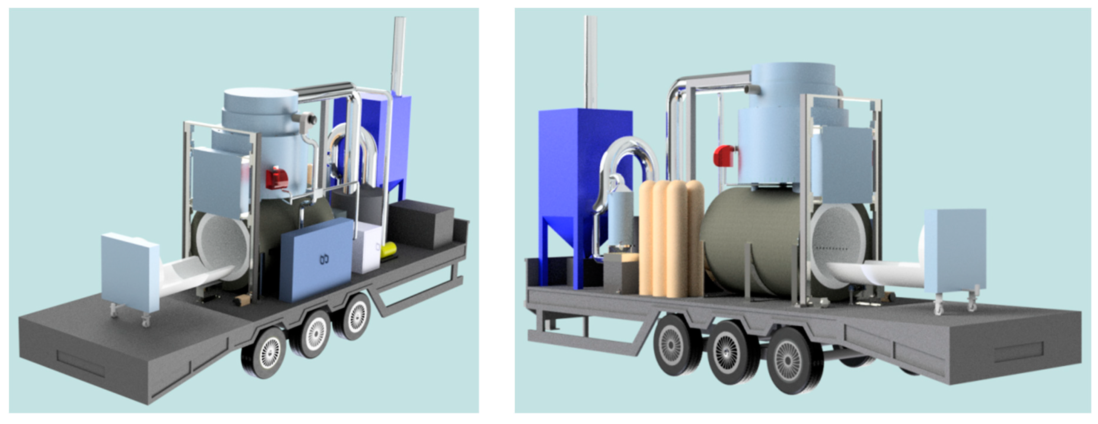
14], the amount of additional fuel only slightly increased, as well as the power of the burner. A larger amount of air also increases the volumetric flow rate of the fan that pushes it into the chamber. From the incinerator operation point of view, this is not a problem due to the fact that devices such as a burner or fan are selected by the designer, taking into account a change in the working conditions. However, attention should be paid to the change in the total volumetric flue gas flow rate, which determines the dimensions of the secondary chamber. A chamber with too small volume does not provide sufficient retention time for the exhaust gases at the required high temperature, ensuring a destruction of the pathogens and microorganisms. It is also a key issue for a design of the entire device dimensions, in the case of smaller scale incinerators—especially mobile. Its size is limited mainly by traffic regulations, regarding the installations carried on trailers, therefore the most optimal solution, characterized by the smallest dimensions, is searched for. Oversizing of the device is associated with higher investment and operating costs and it can also completely eliminate the possibility of unit adaptation to the traffic regulations.
It should be remembered that the calculations were carried out for the same, relatively high value of the excess air coefficient
λ, which was a key factor influencing the final volumetric flue gas flow rate and the volume of the secondary chamber. Due to the hazardous nature of medical waste, its high values are recommended in order to minimize the risk of incomplete combustion and to provide residual oxygen in the flue gas at a minimum level of 6% [
22]. It is possible to reduce the combustion chamber volume by reducing
λ. However, it has its limitations, for example, a reduction of
λ from 2.3 to 2, in the case of waste from Italian hospitals, caused a temperature increase in the chamber above assumed (1100 °C). The heat rate, generated during burning waste with this composition, was higher than the rate of heat needed to raise the temperature of dry products and ash material to the required value and evaporation of moisture. On the other hand, in the case of waste from Iranian hospitals, with the
λ = 2 factor, such a situation did not occur.
5. Discussion
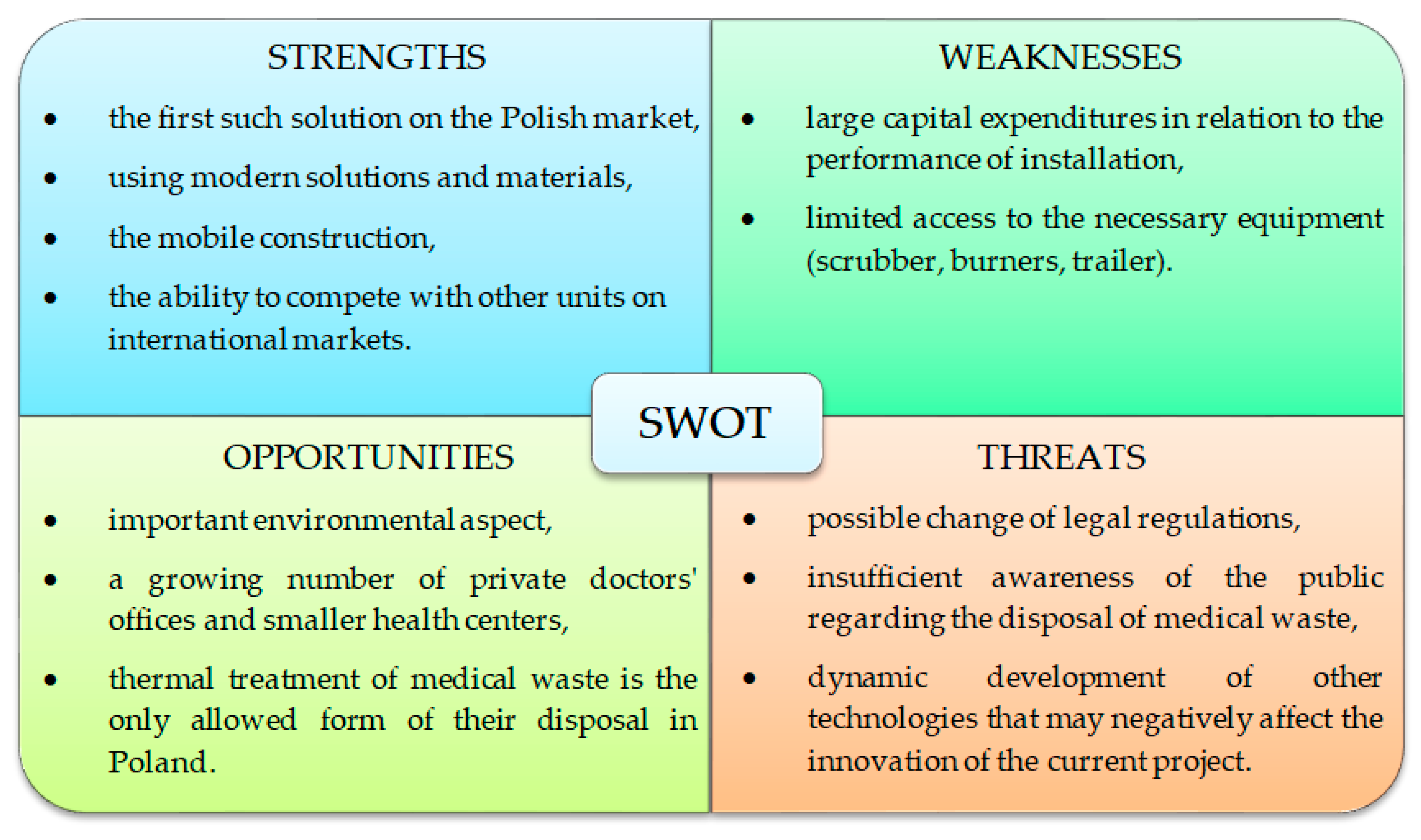
Introduction of the proposed solution to the market requires the analysis of its advantages and disadvantages, as well as evaluation of a profitability of the entire investment. A helpful technique for conducting such a recognition and creating an appropriate marketing strategy is the SWOT analysis (Strengths Weaknesses Opportunities Threats) [
25].
The profitability analysis started with strengths. In first place is the uniqueness of the proposed solution and its conformity with the law in Poland. The Polish market currently does not have a mobile unit for the disposal of medical waste which would meet the legal requirements, especially in regard to the automatic waste feeder. The second advantage of the proposed solution is a mobility of the unit. Thanks to this, it can work in various locations, depending on the needs of the environment. Not only health care units located away from larger waste incineration plants, but also the places of the disasters or epidemic outbreaks may be among the recipients of the service. Thanks to the mobility of the unit and modern solutions used in it, it can compete with the offers of other companies on the international market. The unit can also dispose of other types of waste. Therefore, during a reduced demand for the disposal of medical waste, the incinerator can work as an animal crematorium or incineration plant for the non-infectious waste.
The weaknesses of the proposed unit include, above all, a large investment costs. Usage of innovative materials, as well as devices at non-typical dimensions and features, mostly designed against order, is associated with an increase in the construction costs.
The factors formulated as opportunities have a significant impact on determination of the mobile medical waste incinerator profitability. The most important are the environmental and legal aspects. The medical waste, due to its properties, is hazardous and the issue of its correct disposal is extremely important. The designed unit ensures neutralization of the waste in a manner that is required by very restrictive Polish law. Usage of the three-stage flue gas cleaning system ensures consistence with emission standards, while the relatively small maximum weight of the waste once incinerated and unit capacity as well as the automation of the process allow for immediate interruption in the case of any irregularities. Mobility of the unit reduces the risk of spreading infectious substances, because the waste is disposed of at the place of origin. It solves the problem of waste transportation, special equipment of the cars for this purpose, re-storage of the waste at the landfill belonging to a given stationary incineration plant and a subsequent transport to the incinerator. In addition, by disposing of medical waste at the place where they were created, it is not possible to violate the Proximity Principle, which is the overriding rule for dealing with the hazardous waste. It is also easier to record documentation related to the entire disposal procedure. By burning the waste only from one clinic, cabinet or other health care facility, it is possible to determine the weight of waste for disposal and its composition without any problem. This minimizes a risk of mistakes and omissions regarding the completion of documents confirming the disposal of waste, and such information can be issued immediately for the owner of the institution transferring the waste for incineration. Due to an increasing number of small health care facilities producing small amounts of waste, the mobile incinerator would allow for their safe disposal, while meeting all legal regulations and maintaining environmental requirements. It could also support the work of larger incinerators in the case of sudden shutdowns of the installation.
An implementation of the project also involves threats. Despite an adaptation of the installation to the law applicable in Poland, the legal regulations may change. The awareness of the observers of the treatment of medical waste plays an equally important role. A large number of the opponents of thermal treatment usage for the medical waste could adversely affect the perception of the designed unit. Therefore, the society should be informed about the principles of operation of such an installation and the technologies used in it.
A significant threat is connected with a possibility of the new method of medical waste utilization appearance. If the new, cheaper method, without the combustion process is proposed and additionally it meets all the requirements of the Act, this would lead to a lack of demand for the designed unit. However, the unit can be improved towards the new requirements and still be competitive with the new solution.
Figure 7 shows a matrix diagram regarding an initial SWOT analysis, containing the most important aspects regarding the strengths, weaknesses, opportunities and threats related to the construction of the proposed mobile medical waste incinerator.


