Article

Resonance Detection Strategy for Multi-Parallel Inverter-Based Grid-Connected Renewable Power System Using Cascaded SOGI-FLL

1
School of Electrical Engineering, Southeast University, Nanjing 210096, China
2
Jiangsu Provincial Key Laboratory of Smart Grid Technology and Equipment, Nanjing 210096, China
3
State Grid Jiangsu Electric Power Co., Ltd. Research Institute., Nanjing 210096, China
*
Author to whom correspondence should be addressed.
This paper is an extended version of our paper published in: W. Cao, D. Fan, K. Liu, J. Zhao, L. Ruan and X. Wu, “Resonance Detection Strategy for Multiple Grid-Connected Inverters-Based System Using Cascaded Second-Order Generalized Integrator,” 2018 International Power Electronics Conference (IPEC-Niigata 2018 -ECCE Asia), Niigata, 2018, pp. 3010–3014.
Sustainability 2019, 11(18), 4839; https://doi.org/10.3390/su11184839
Submission received: 12 July 2019 / Revised: 28 August 2019 / Accepted: 31 August 2019 / Published: 4 September 2019
(This article belongs to the Special Issue Power Electronics for Renewable Energy Systems)

Abstract

:
The increasing use of multi-parallel grid-connected inverters introduces both high-quality and high-capacity power, while it tends to cause a resonance instability problem. A resonance damper can virtualize a resistor at resonant frequency to suppress the instability effectively, but the resonant frequency should be detected primarily. However, the resonant current or voltage is severely distorted and oscillating, which will lead to the resonant frequency extraction being more difficult. To address it, this paper proposes a resonance detection strategy based on the cascaded second-order generalized integrators (SOGI) and the normalized frequency locked loop (FLL). The cascaded structure ensures the accuracy by completely filtering the fundamental component from the detected voltage or current, and the normalization accelerates the frequency detection. The proposed method can be used as a crucial unit of the resonance damping controller. Finally, the performance of the proposed method is verified by the MATLAB-based simulation and Hardware-in-the-Loop (HIL)-based emulation results.

1. Introduction

In order to cope with climate change and the energy crisis, the renewable energy generation, especially the photovoltaic and wind power, is developing rapidly [1,2]. In general, the grid-connected inverters, as the interface between the renewable power and the grid, play important roles in injecting high-quality power into the grid [3,4]. A typical multi-parallel grid-connected inverters system is demonstrated in Figure 1. Although the technological advance of multi-parallel grid-connected inverters has promoted the rapid development of distributed generation, it also results in a complex coupling relationship between the grid and inverters [5,6], which tends to bring about the resonance [7,8,9,10]. The resonance in a multi-parallel inverters system not only affects the power quality, but also brings about other problems, such as damaging the relay protection devices and threatening the security and stability of the power grid.
A micro-grid system with wind turbines, energy storage, photovoltaic and resonance damper is shown in Figure 2. Instead of reshaping the damping characteristic of inverters [11], the active damper aims to dynamically suppress the resonance through increasing a damping resistance at the resonant frequency [4,12,13]. However, the active damper only operates at the resonant frequency. Therefore, the frequency at the resonant point must be precisely obtained to achieve appropriate damping adjustment. There are various techniques to estimate the frequency or phase, such as discrete Fourier transformation, Kalman filter, phase locked loop (PLL), Wavelet transformation, etc. Among these techniques, PLL receives wide attention because of its excellent performance and simple structure [14,15]. It behaves well in normal cases, but the excellent dynamical performance is at the expense of disturbance resistance ability. Moreover, it cannot be applied in the case of uncertain frequency. Discrete Fourier transformation and Wavelet transformation are often used to detect resonance frequency [16]. The former divides the whole frequency band evenly, which means the information at the resonant point could be neglected easily. The latter analyzes the input signal according to its frequency bands so that only the resonance frequency range can be obtained, rather than the accurate and complete resonance information. The traditional resonance detection methods are limited because of the time variation and amplitude distortion of the resonance current.
The Second-Order Generalized Integrator-Frequency Locked Loop (SOGI-FLL) has been studied extensively in recent years, and is composed of two parts: traditional SOGI and FLL [17,18,19,20,21,22]. The former can generate two orthogonal output signals from the input signal and the latter detects the input signal frequency and provides it to the second-order generalized integrator [19]. SOGI-FLL that only extracts the frequency information simplifies the algorithm and reduces the computation time and complexity [21,23,24]. Multiple paralleled SOGI with a common FLL is proposed to estimate the input signal with multiple components correlated to the fundamental frequency [25,26]. However, it is proved in Reference [27] that the performance of this method will be deteriorated when there are subharmonics in the input signal. The cascaded ANF (Adaptive Notch Filter) structure is proposed in Reference [28] to detect several unknown resonant components from an input signal. However, there is commonly only one resonant component when the multi-paralleled inverters system is unstable, and the structure is too redundant for only one resonant frequency. Besides that, the effect of algorithm improvement is not obvious and FLL is vulnerable to the grid and SOGI because of the lack of normalization.
In this paper, a typical multi-parallel grid-connected inverters system is modeled and analyzed, which will clarify the objective of resonance detection. In order to increase the damping at the resonant point, the resonance detection strategy based on SOGI-FLL is presented. The operating principle of the traditional SOGI-FLL is analyzed in frequency domain and then the improved cascaded and normalized SOGI-FLL structure is proposed to extract the resonant component from the fundamental component. Through the verification of MATLAB (vR2018b, Natick, MA, USA) simulation and HIL (Hardware-in-the-Loop)-based emulation, it can be seen that the proposed SOGI-FLL structure can effectively and quickly detect the resonant frequency in spite of the fact that the resonant frequency is uncertain and the signal to be detected is oscillating.

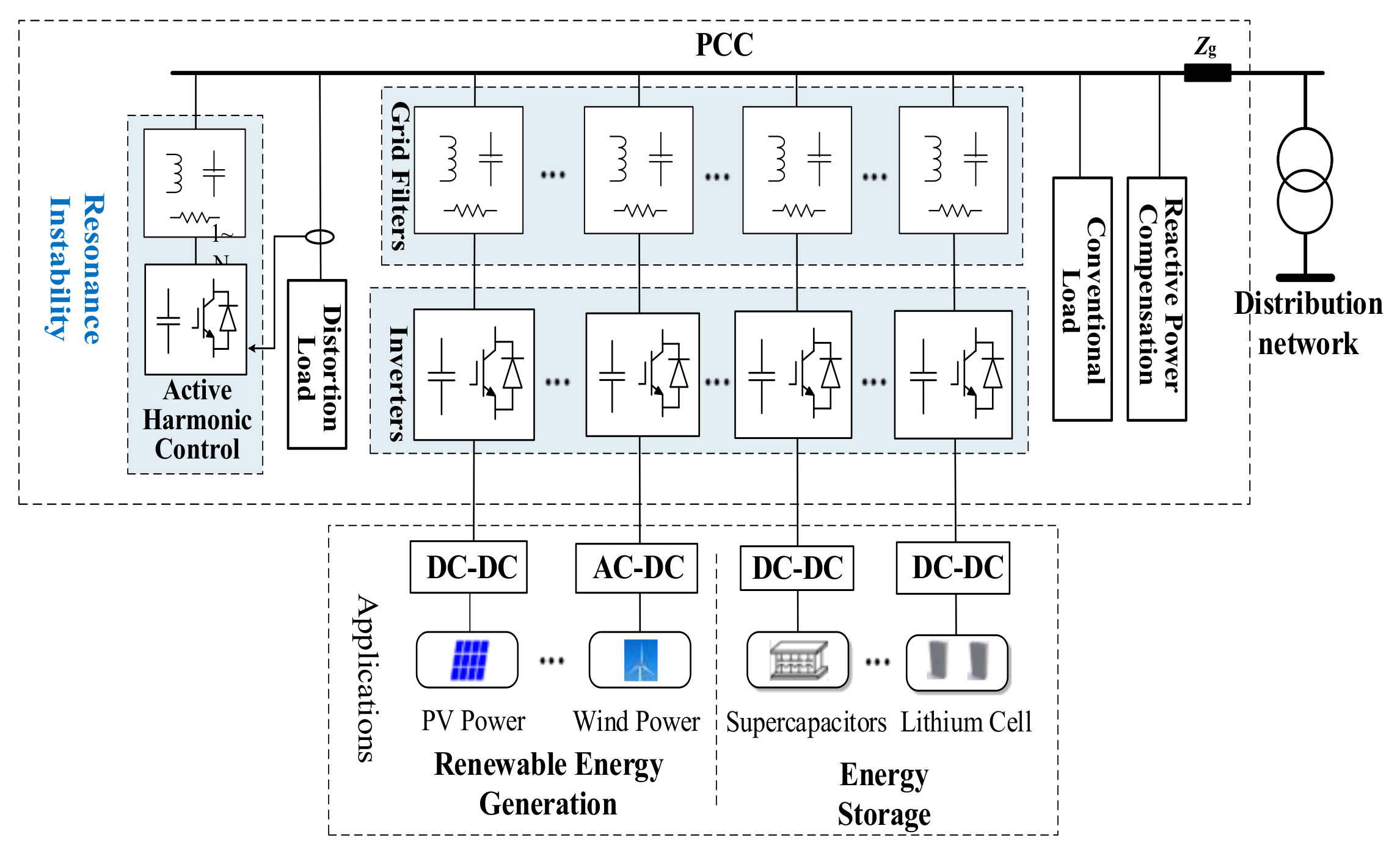
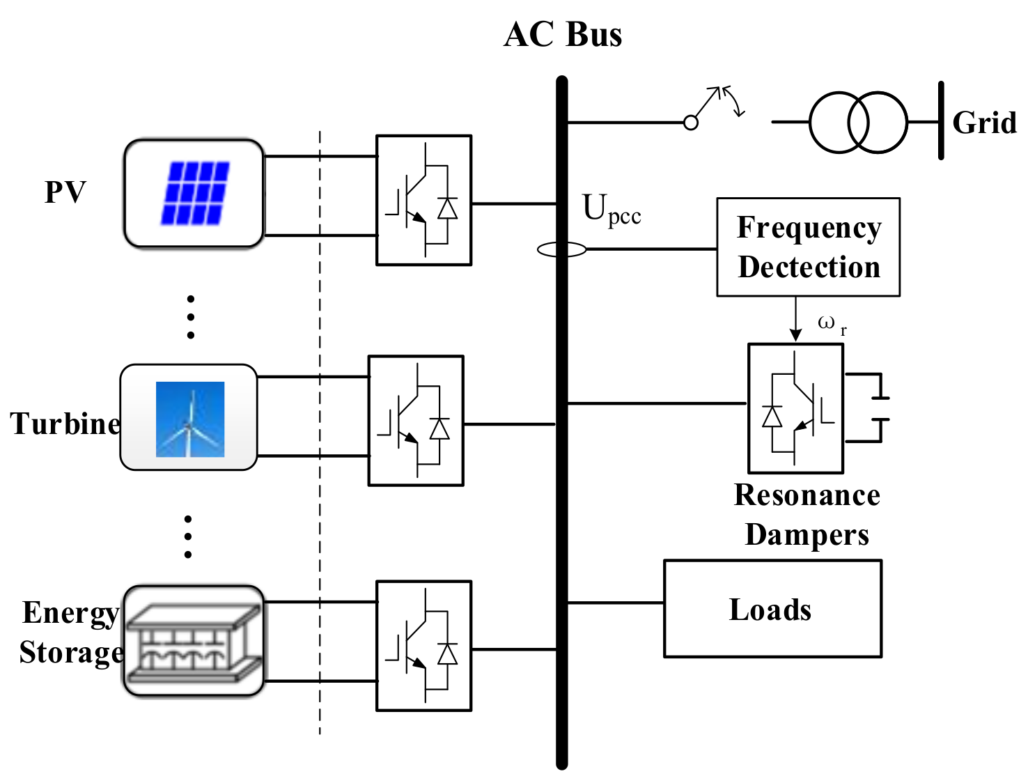
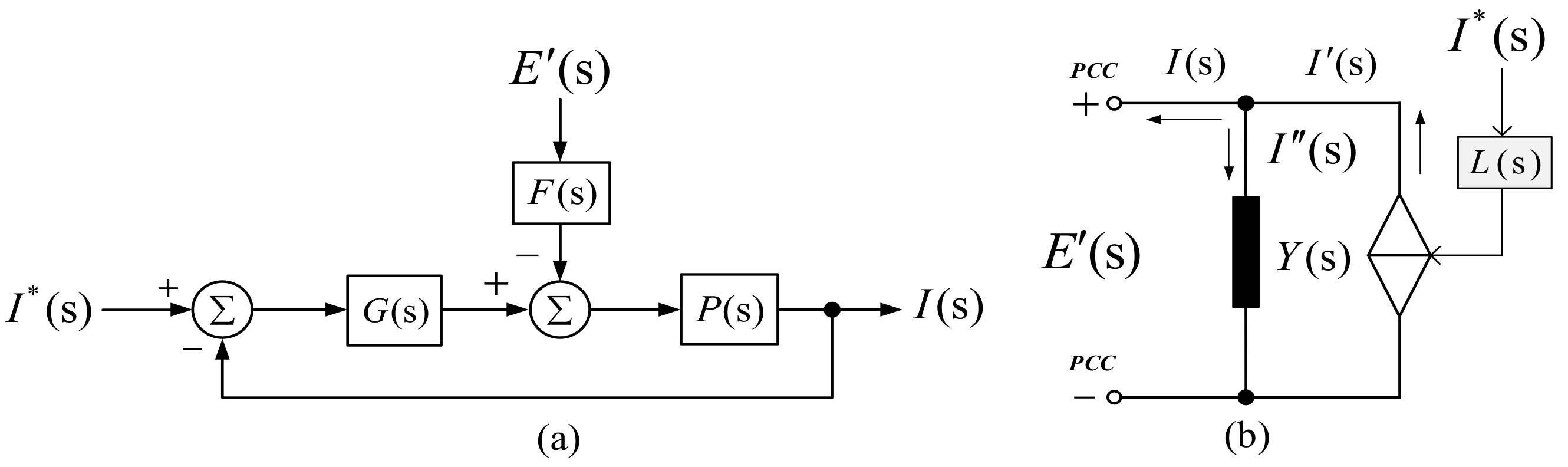
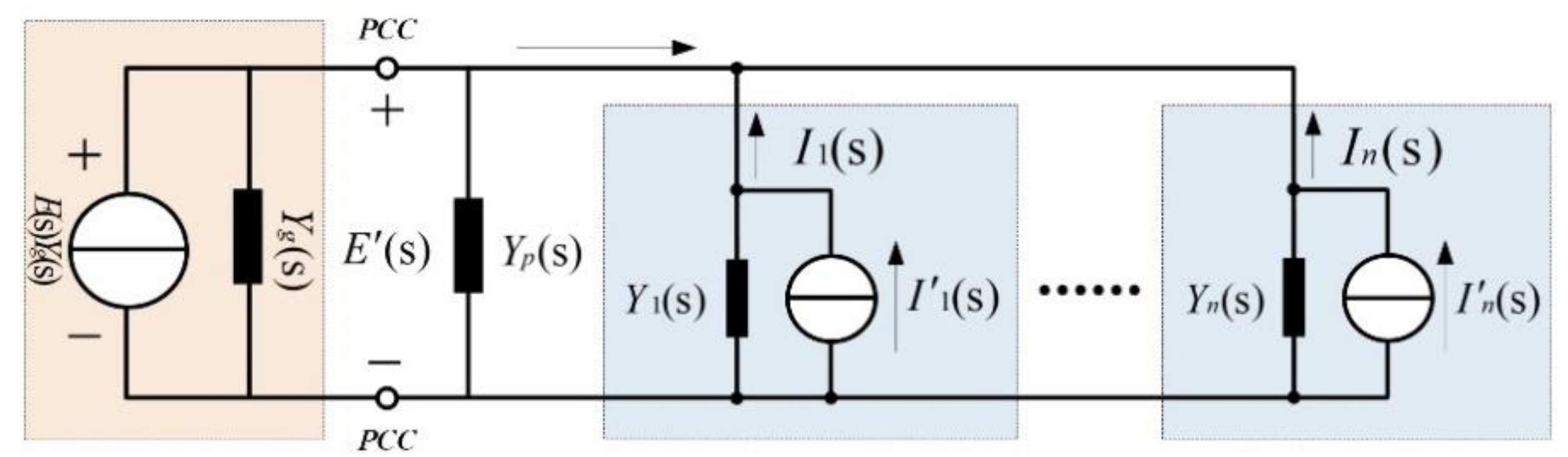
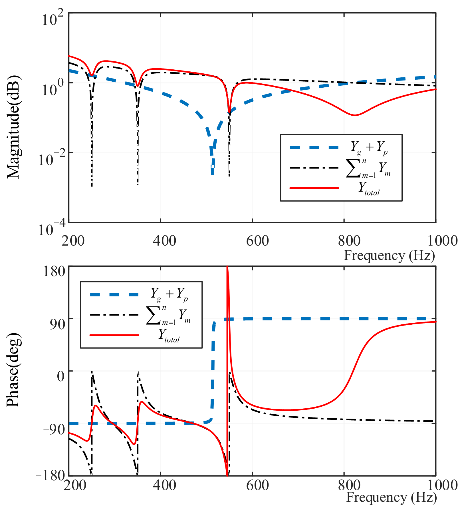
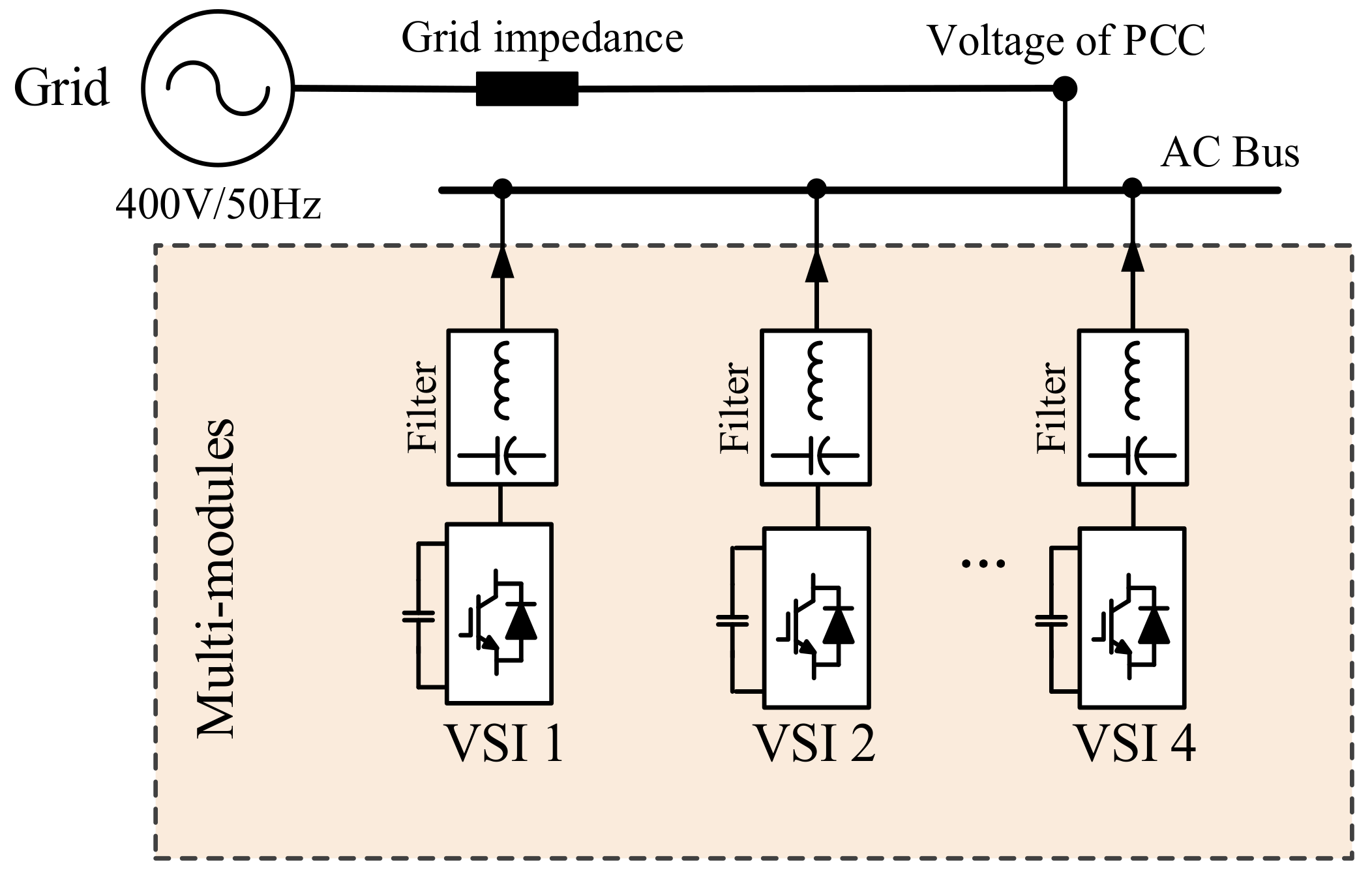
2. Modeling and Analysis of Multi-Parallel Inverters System

Due to the existence of grid impedance, there is a complex coupling relationship between the inverters in the grid, which is the main cause of the resonance instability [29]. In this section, the typical multi-parallel grid-connected inverters system is modeled and analyzed, which will clarify the objective of resonance detection theoretically. The current loop model of a typical single-inverter grid-connected system is shown in Figure 3a. G(s) represents the controller, F(s) is the disturbance gain of current loop, P(s) is the control objective, and E′ represents the PCC (Point of Common Coupling) voltage.
I ( s ) = I * ( s ) L ( s ) I ( s ) E ( s ) Y ( s ) I ( s )
where, H ( s ) = C i ( s ) e s T d P ( s ) , L ( s ) = H ( s ) 1 + H ( s ) = C i ( s ) e s T d P ( s ) 1 + C i ( s ) e s T d P ( s ) , and Y ( s ) = 1 Z ( s ) = D ( s ) P ( s ) 1 + C i ( s ) e s T d P ( s ) .
The output current can be expressed as an admittance form, as shown in Equation (1). L(s) is the controllable current source gain, and Y(s) is the current loop admittance [30]. According to Equation (1), the Norton equivalent model consisting of controllable current source and current loop admittance can be obtained from the perspective of circuit port equivalence, as shown in Figure 3b. The admittance equivalent model in Figure 3b can be used to analyze the relationship between the PCC voltage and output current, and then obtain the response expression of each part of the whole parallel system. Furthermore, it can be applied to analyze the stability of the multi-parallel inverters system [31,32].
Through using the current loop admittance model of a single inverter, as mentioned above, the equivalent model of the multi-inverters parallel system can be further established, as shown in Figure 4. Yp represents equivalent admittance of passive devices, Yg is the grid equivalent admittance, and Ym represents the admittance of each current loop (m = 1, 2, 3, …, n), and the PCC voltage can be obtained as follows:
E ( s ) = E Y g + m = 1 n I m / Y g ( s ) + Y p ( s ) + m = 1 n Y m Y t o t a l
It can be seen that the PCC voltage can be considered as the response of the total excitation of the parallel system (superposition of all the equivalent current sources) to the total admittance of the parallel system (Ytotal, the sum of all the admittance, is defined as global admittance in this paper). In addition, when the grid admittance Yg is large (namely, the grid is approximately ideal), the PCC voltage is basically not affected by the parallel system of each part. On the contrary, when the grid admittance Yg is relatively small, all parallel inverters will affect the PCC voltage through the global admittance.
Figure 5 shows a typical resonance phenomenon. The passive admittance (Yg + Yp) and the active admittance (the sum of the current loop admittance of all inverters, ΣYm) create a complex coupling relationship at the frequency of 550 Hz, which results in the resonance instability in the grid.

3. The Proposed Cascaded Second-Order Generalized Integrator-Frequency Locked Loop (SOGI-FLL)-Based Resonance Detection Method

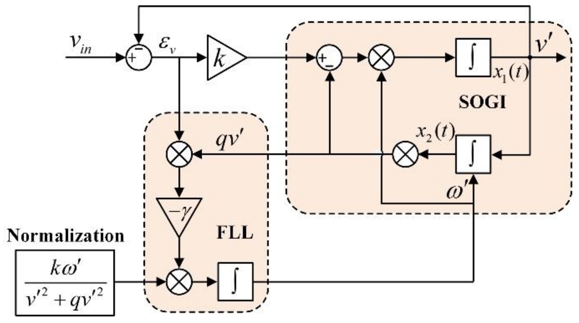
3.1. Frequency Self-Adaptive SOGI-FLL

The frequency adaptability of SOGI-FLL makes the problems of frequency uncertainty and amplitude divergence of resonance signal solvable. The structure of SOGI-FLL is shown in Figure 6, where the resonance frequency is represented as ω′ that distinguishes it from the input frequency ω. v′ and qv′ are the two orthogonal output signals of the self-adaptive filter.
The transfer functions of SOGI-FLL can be written from Figure 6 as:
( a ) : D ( s ) = v v i n ( s ) = k ω s s 2 + k ω s + ω 2 ( b ) : Q ( s ) = q v v i n ( s ) = k ω 2 s 2 + k ω s + ω 2 ( c ) : E ( s ) = ε v v i n ( s ) = s 2 + ω 2 s 2 + k ω s + ω 2
Equations (3a) and (3b) indicate that the detection system in Figure 6 provides band-pass filtering and low-pass filtering characteristic to v′ and qv′, respectively. Besides that, it is obvious that the bandwidth of the band-pass filter is independent of the center frequency ω′ and only depends on the gain k. The static gain of the low-pass filter also depends on the gain k. It can be concluded from Equations (3a) and (3b) that the output qv′ is always 90° lagged from the output v′ [18].
Considering the output qv′ and input signal error εv, they are in-phase when the input frequency is less than the resonance frequency of SOGI (ω < ω′) and in opposition when ω > ω′, as shown in Figure 7. Frequency error signal εf can be effectively adjusted by input error signal εv and output signal qv′, εf > 0 when ω < ω′ and εf < 0 when ω > ω′. Consequently, FLL can gradually regulate the deviation of ω and ω′ by the integrator with the negative gain -γ according to the change of εf until ω = ω′ [20,21].

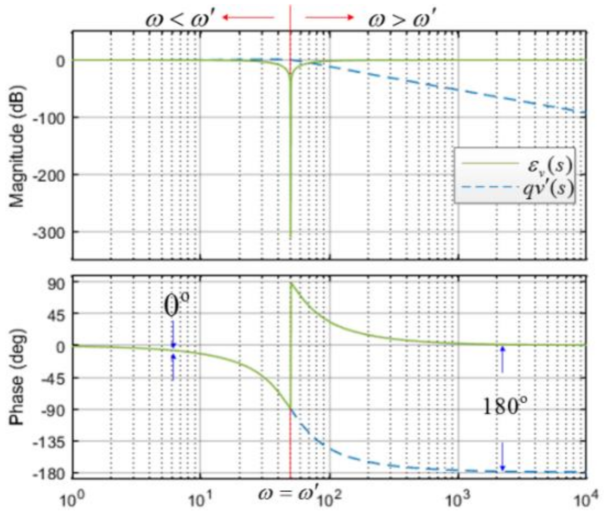
3.2. Mathematical Description of SOGI-FLL

The state-space equations of SOGI-FLL can be derived from the system shown in Figure 6 and are given in Equations (4)–(6), where (x1(t) x2(t))T in Equation (4) is the state vector of the second order generalized integrator, and y in Equation (5) is the output vector. The behavior of the frequency locked loop is illustrated by Equation (6).
x = x 1 ( t ) x 2 ( t ) = k ω ω 2 1 0 x 1 ( t ) x 2 ( t ) + k ω 0 v i n ( t )
y = v ( t ) q v ( t ) = 1 0 0 ω x 1 ( t ) x 2 ( t )
ω = γ x 2 ω ( v i n x 1 )
Under the condition of stable operation, there is ω = ω′ and ω′ = 0 [33], Equation (4) can be deduced to:
x ˙ ¯ 1 = ω 2 x ¯ 2
where, the variables in steady state are denoted with a bar over them.
The lock frequency error in steady state can be derived from Equation (4) as:
ε f ¯ = ω x 2 ( v i n x 1 ¯ ) = x 2 2 k ω 2 ω 2
Substitute Equation (8) into Equation (6),
ω = γ k x 2 2 ω 2 ω 2
Considering ω ω in this case, ω 2 ω 2 is approximately equal to 2 ( ω ω ) ω , Equation (8) gives rise to Equation (10).
ω = γ k x 2 2 2 ω ω ω
Defining the frequency error as δ = ω− ω, Lyapunov energy function and its gradient equation are established as follows:
V ( σ ) = σ 2 > 0 d V ( σ ) d t = 1 2 σ σ = 1 2 ω ω 2 ω + ω γ k x ¯ 2 2 < 0
According to the Lyapunov stability criterion, FLL is progressively stable. Supposing a given input signal vin = Vsin(ω1t) + Veatsin(ω2t), which can be considered as a signal mixed by a fundamental signal v1 = Vsin(ω1t) and a divergent resonant signal v2 = Veatsin(ω2t), when the system operates steadily, the transfer functions of input signals error are εv1(s) and εv2(s) caused by v1 and v2 respectively, they can be easily obtained by Equation (3c), and the Bode diagram of εv1(s) and εv2(s) is illustrated in Figure 8. The gain is −90 dB at ω < ω1 and 25 dB at ω < ω2, which implies the input signal error ε = εv1 + εv2 can filter the fundamental component completely and keep the resonant component so that it can be used to detect the resonance frequency.

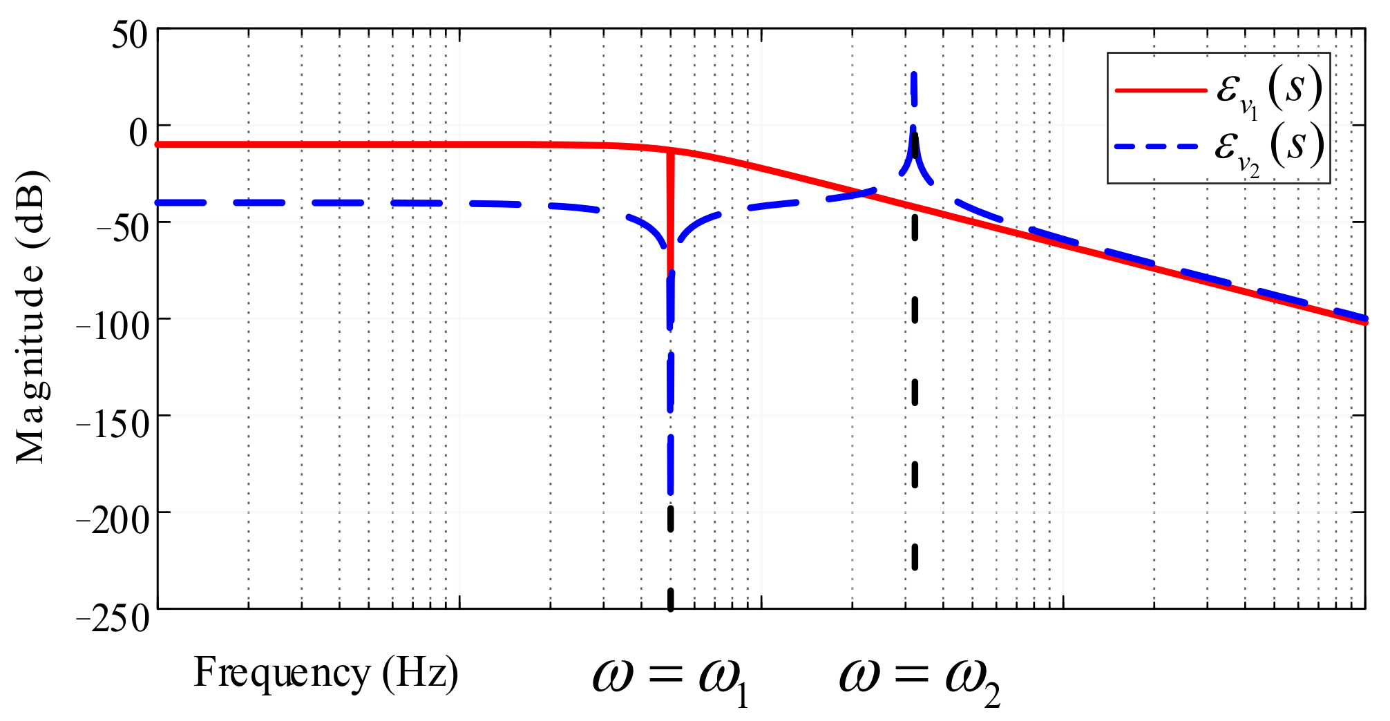
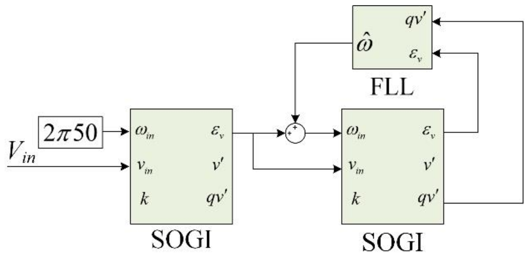
3.3. The Proposed Cascaded and Normalized SOGI-FLL Strategy

Equation (11) reflects the convergence rate of the signal and Equation (10) can be converted to Equation (12).
ω = 2 γ k ω V 2 ω ω
It should be noted that the relevance of the frequency ω′ and magnitude V to the rate of convergence can be eliminated through normalizing the self-adaptive parameter γ. Then, the normalization achieved through multiplying the correlation coefficient could make the derivative function of the output frequency to be related only to the adaptive parameter γ. The normalized derivative of the output frequency can be expressed as:
ω = 2 γ ω ω
Figure 9 shows the structure of normalized SOGI-FLL. The cascaded and normalized SOGI-FLL is proposed to separate fundamental component and extract the resonance components, as show in Figure 10. The structure is divided into two parts. The former part, SOGI (without FLL), sets its extraction frequency as the fundamental frequency. The latter part is the normalized SOGI-FLL that uses the output signal error of the former SOGI to extract resonance component.
Eb(s) and Dr(s) are the transfer function of the former and latter parts respectively, and the output of cascaded SOGI-FLL can be expressed as:
v r = D r ( s ) V i n E b ( s )
The Bode diagram of (14) is shown in Figure 11. The gain is −170 dB at 50 Hz. The fundamental frequency current can be thoroughly filtered by the former part. In addition, the resonant frequency of the current information has been retained, because the gain is 0 dB at the resonance point.

4. Simulation and HIL-Based Emulation Results

To verify the validity and rationality of the proposed strategy, the MATLAB model and hardware-in-the-loop emulation platform (as shown in Figure 12) are established. The simulation is built to validify the advantage and effectiveness of the cascaded and normalized SOGI-FLL and the HIL-based emulation is built to validify the effectiveness of resonance suppression using the proposed method. It should be noted that the resonance instability is difficult to be emulated on the practical experimental platform due to security risks. Therefore, the HIL platform is adopted in this paper to verify the proposed method. The power hardware circuit (four parallel grid-connected voltage source inverters (VSIs)) is implemented in the RT-Box. A designed controller based on DSP (TMS320F28335) and field programmable gate array (FPGA (EP2C5Q208C8)) is connected to RT-Box and can be tested completely to achieve optimal control performance without the risk of damaging the power hardware. The sampling frequency is 20 kHz, and switching frequency is 10 kHz. The transformation between actual system and virtual system is shown in Figure 13. A similar application can be found in the paper published on IEEE Transactions on Industrial Electronics by Freijedo from EPFL (Swiss federal Institute of Technology in Lausanne) [34].

4.1. MATLAB-Based Simulation Results

Based on Figure 9 and Figure 10, the MATLAB simulation platform can be built. The accuracy and speed of the proposed strategy are difficult to be assessed in the unstable grid-connected system due to the fact that there are several resonant components rather than only one. Thus, the input signal is simulated by a fundamental signal mixed with a divergent resonant signal in this paper. Table 1 shows the parameters of the mixed input signals and SOGI-FLL. Especially, the value of k needs to be considered comprehensively. The larger the value of k, the faster the dynamic response speed of SOGI. However, the filtering effect of SOGI will get worse when k increases. Therefore, a compromise is needed. Through the validation and comparison, it can be seen that the dynamic performance is optimal when k equals 1.414, and it is universal. γ mainly affects the frequency adaptability of FLL. Before normalizing γ, it is highly nonlinear and needs to be calculated repeatedly. With the normalization, γ is neither affected by power grid nor by SOGI. As mentioned in Reference [30], the value of γ can be set according to the following expression: γ = −5/ts, ts is the expected setting time. In this paper, ts is 0.05 s, so γ is chosen as −100. Using these parameters, a mixed input signal which contains both a fundamental component and a resonant component would be acquired. When the resonant frequency changes, the performance of cascaded SOGI-FLL dynamic extraction of resonant frequency can be verified.

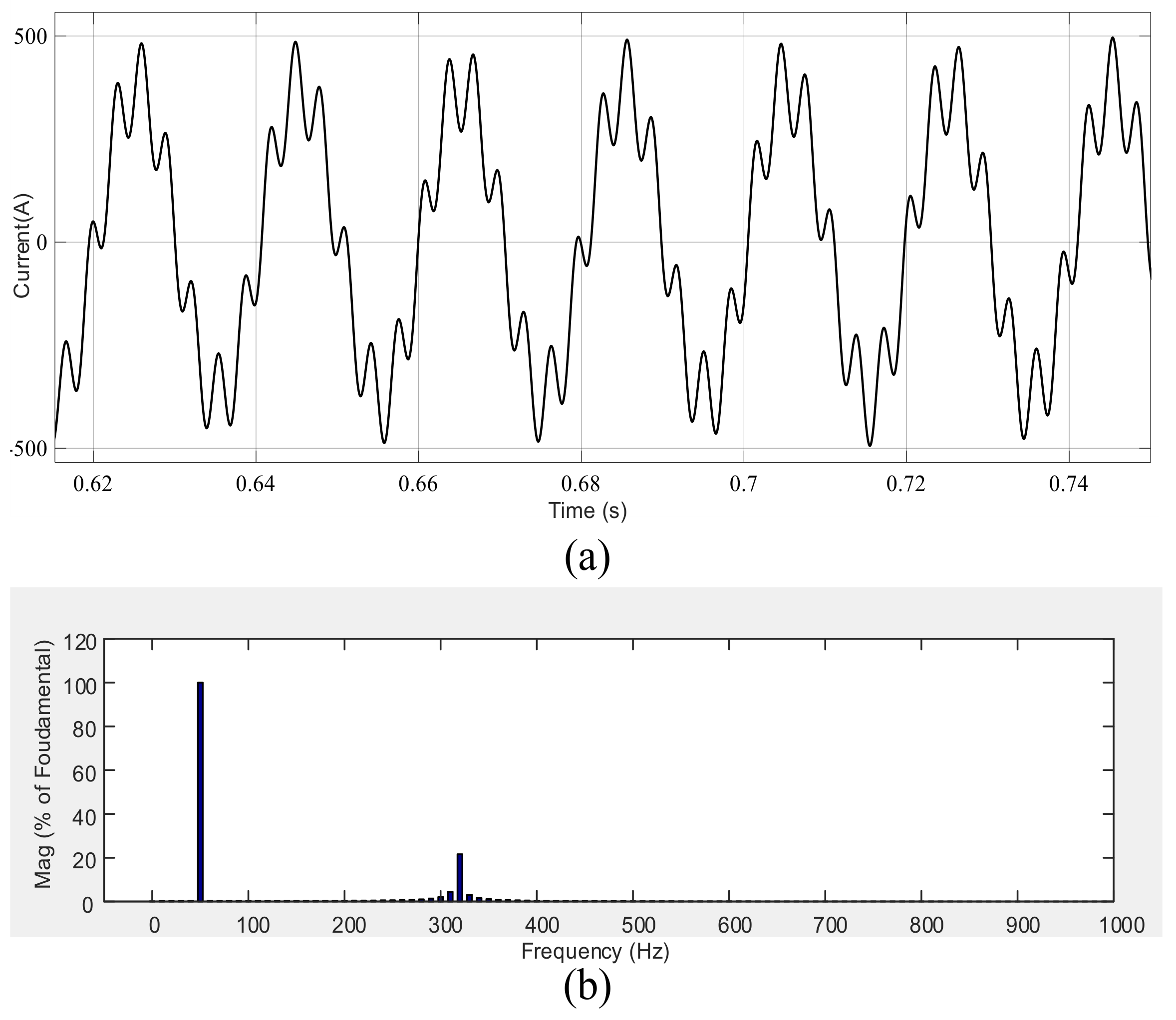
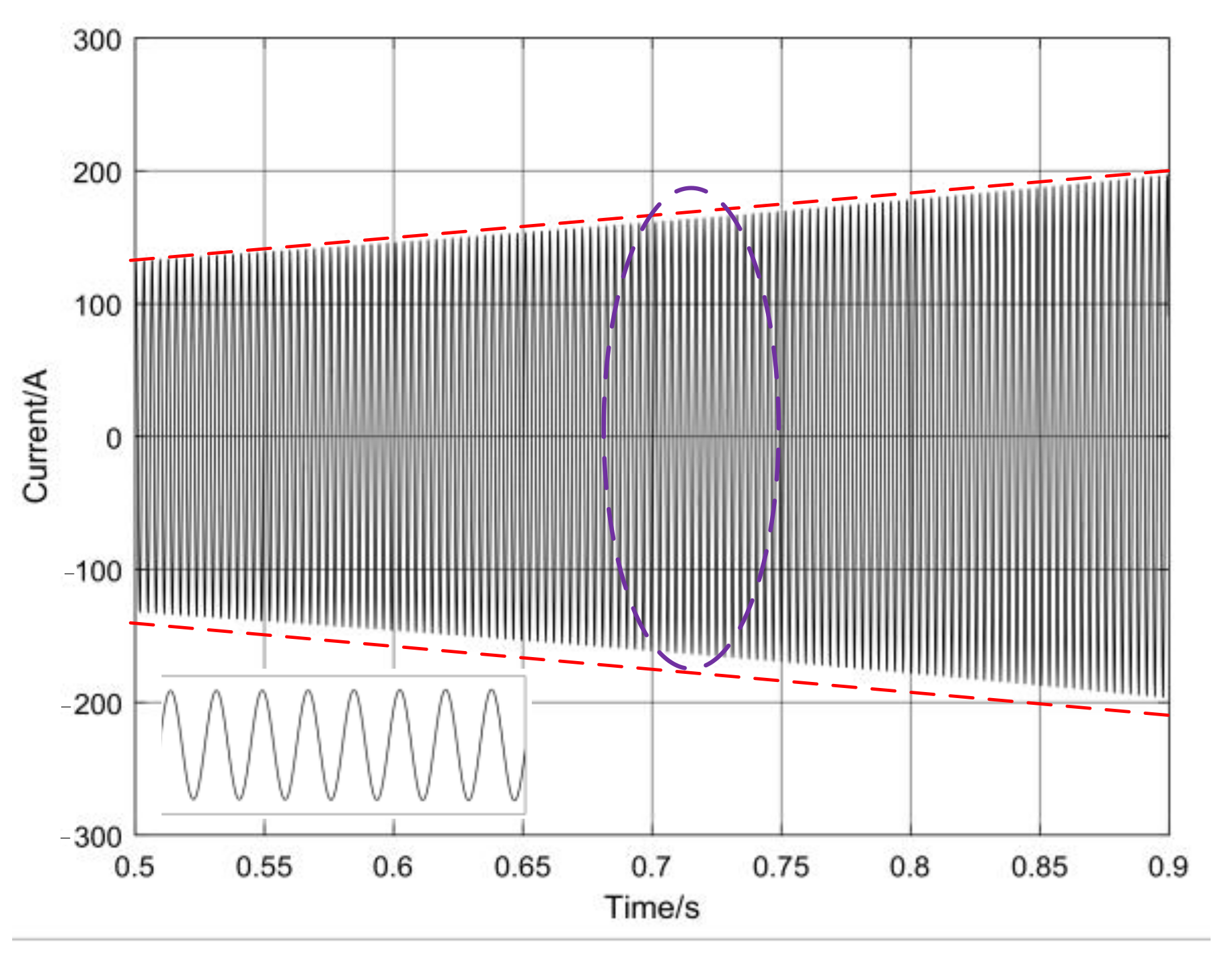
4.1.1. Resonance Extraction Effect Validation

To verify the self-adaptive extraction performance of the proposed cascaded SOGI-FLL-based strategy, the simulation of the fundamental waveform mixing the resonance signal i1 is built. As shown in Figure 14, the current has been mixed by 320 Hz resonance current component. The THD (Total Harmonic Distortion) of the input signal will increase because of the resonance. Through the proposed SOGI-FLL method, the resonance component is extracted, as shown in Figure 15. It is obvious that the resonant component increases from about 100 A to 200 A.
The resonance frequency extracted by the proposed cascaded SOGI-FLL is shown in Figure 16, and the frequency of the resonance component is about 320 Hz, and changes to 800 Hz suddenly at 1.5 s. It is obvious that the proposed cascaded SOGI-FLL responds to the frequency change quickly and takes about 0.1 s to track the new resonant frequency.

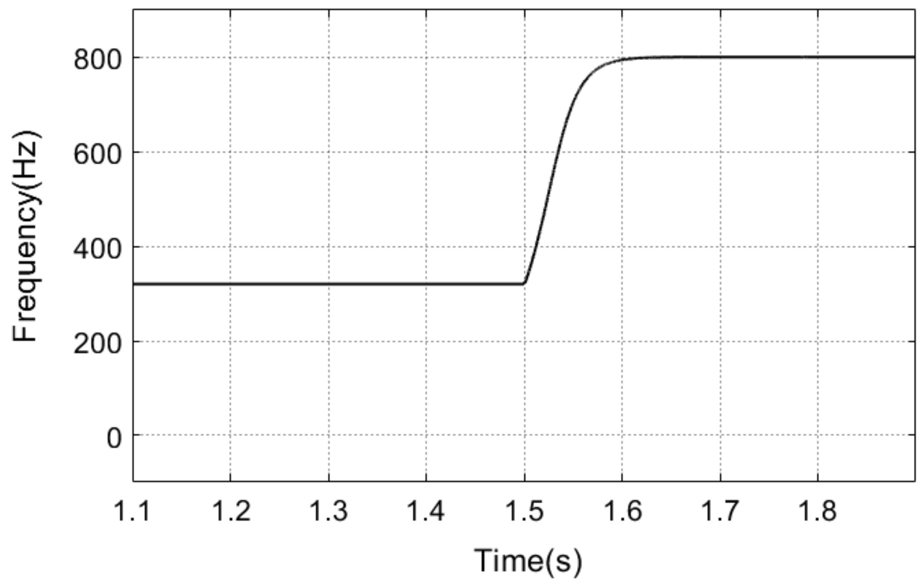
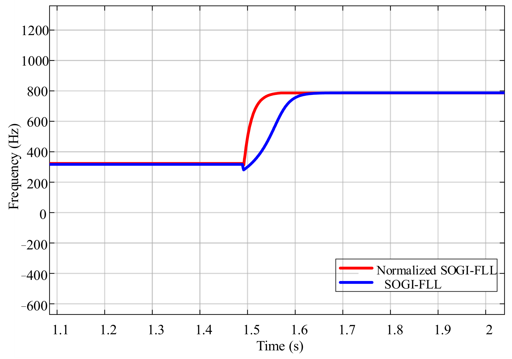
4.1.2. Comparison of Detection Speed

The comparative result of detection speed is shown in Figure 17. The frequency of the resonance component changes from 320 Hz to 800 Hz suddenly at 1.5 s. The blue curve represents the resonant frequency detected by the unnormalized cascaded SOGI-FLL while the red curve represents the resonant frequency detected by normalized cascaded SOGI-FLL. It is obvious that both methods can quickly respond to the resonance component and track the resonant frequency without the static error. However, the cascaded and normalized SOGI-FLL can respond to the frequency more quickly, this is because the normalized FLL is not affected by the amplitude and frequency of the input signal.

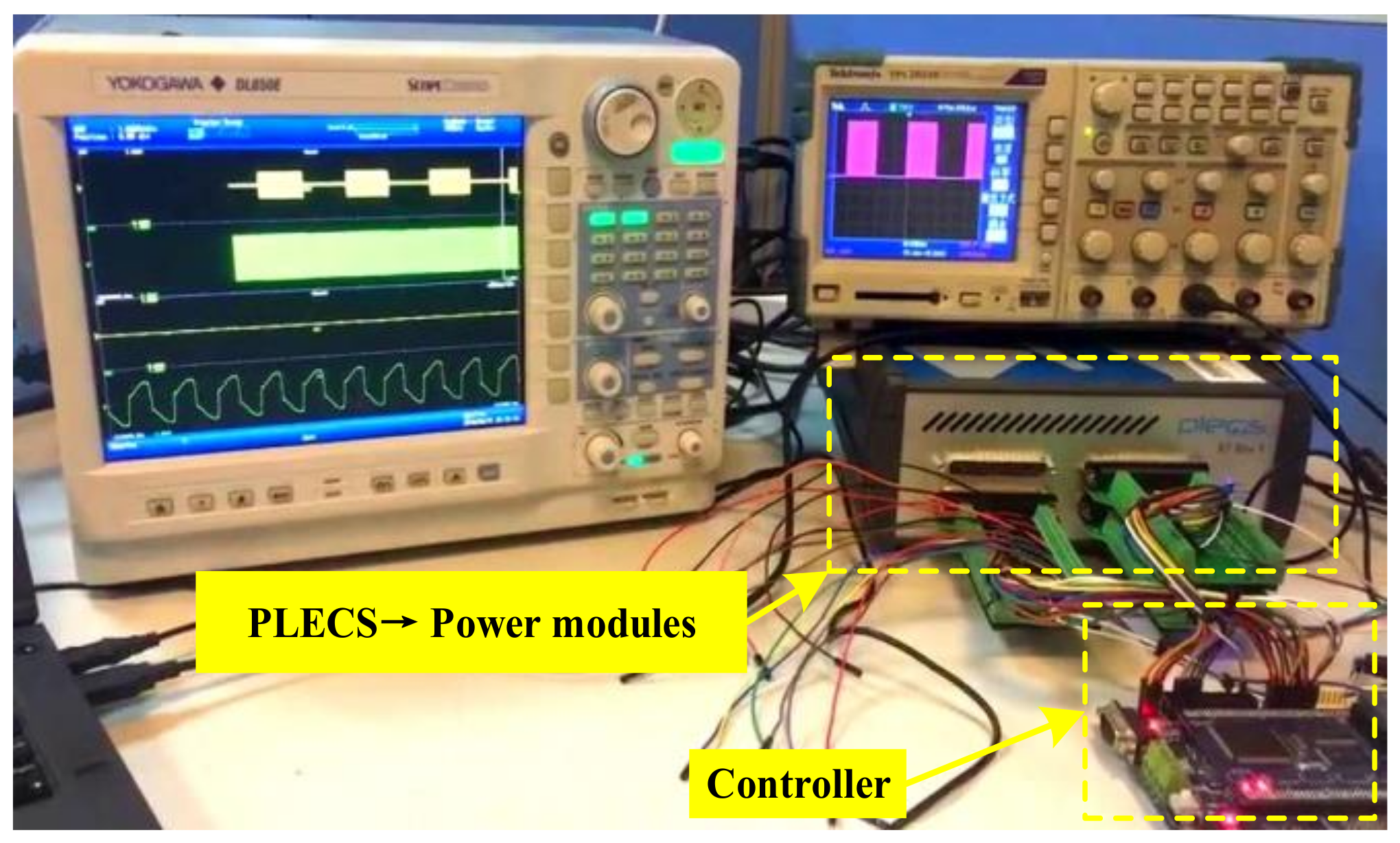
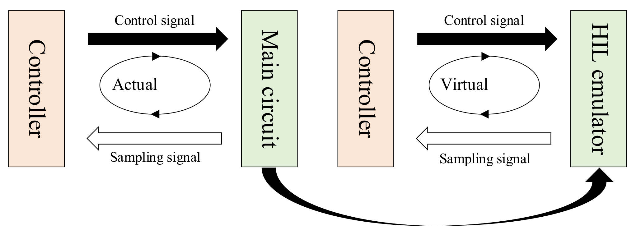
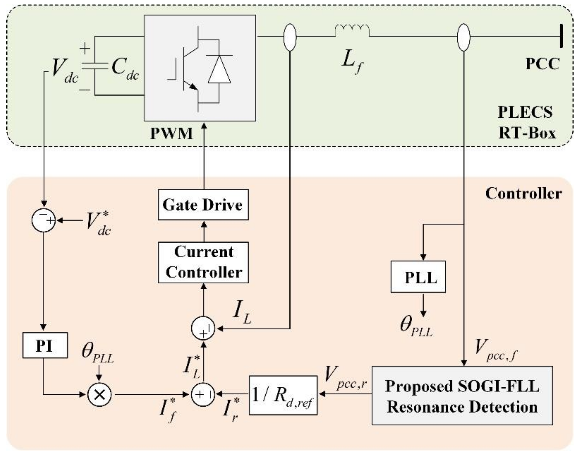
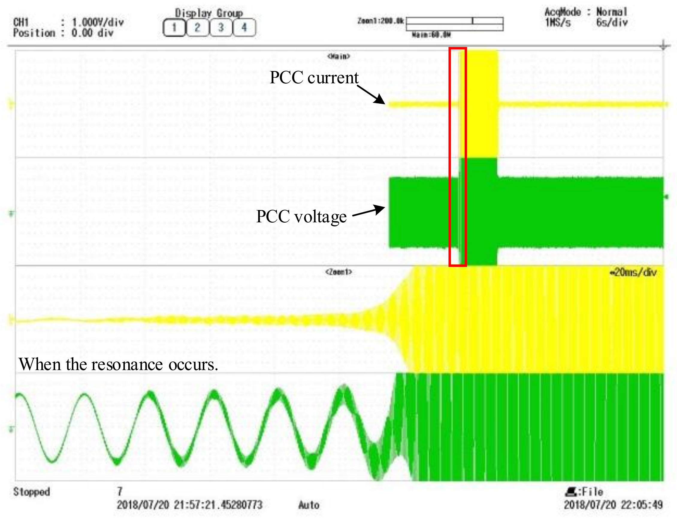
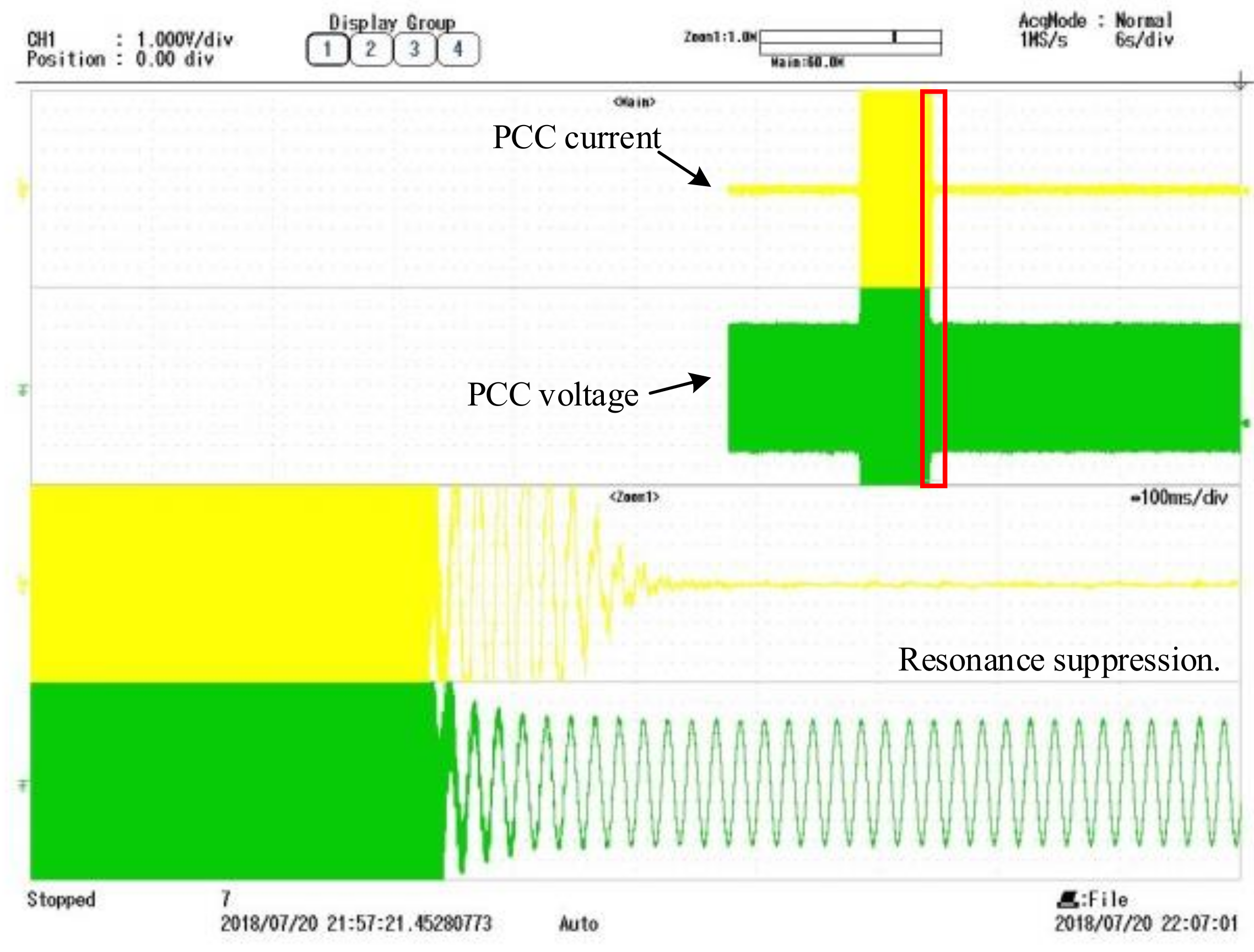
4.2. Hardware-in-the-Loop (HIL)-Based Emulation Results

Figure 18 shows the simulation and HIL-emulation platform, which consists of four traditional grid-connected VSIs. The power hardware circuit is implemented in the RT-Box. To experimentally validate the performance of the resonance detection presented in this paper, a resonance damping controller based on the R-APF (resistive active power filter) method is designed, as shown in Figure 19. The damping resistance Rd,ref is only emulated at the resonance frequency, which can be achieved by adopting the detection strategy proposed in this paper to extract the resonance voltage component from the fundamental voltage component. The effectiveness of resonance suppression will depend largely on the accuracy of the resonance detection.
Figure 20 and Figure 21 respectively, demonstrate the grid-injected current and PCC voltage before and after the resonance damping controller has been taken into operation. The third and fourth subplots in Figure 20 and Figure 21 are the Zoom waveforms of the red box in the first and second subplots. As shown in Figure 20, resonance occurs, and the system becomes instable. The current and voltage waveforms increase dramatically and are extremely distorted. Under the effect of the damping controller, as shown in Figure 19, the resonance is tracked and suppressed quickly, the system resumes stability. The current and voltage waveforms are stable and convergent. The HIL emulation results directly verify that the proposed method can detect the resonance component accurately and can be applied to design a resonance damping controller to suppress the resonance in a multi-parallel inverters system.

5. Conclusions

The resonance generation mechanism in the multi-parallel grid-connected inverters system was analyzed. The SOGI-FLL is frequency-adaptive so that it can be applied to detect the unknown resonant frequency. However, a traditional SOGI-FLL only can extract one frequency and is susceptible to the input signal. In this paper, the cascaded and normalized SOGI-FLL was proposed to separate the fundamental component to detect the resonance disturbances. The MATLAB simulation and HIL-based emulation results show that the improved cascaded SOGI-FLL structure can quickly and effectively detect the resonance disturbances. The proposed method can provide a promising way to detect the resonant frequency for the use of suppressing the resonance in a multi-parallel inverters system, which guarantees the security and stability of the grid.

Author Contributions

Conceptualization, W.C. and K.L.; Data Curation, S.W.; Funding Acquisition, J.Z.; Methodology, S.W. and H.K.; Software, H.K. and D.F.; Validation, S.W.; Writing—Original Draft, K.L., S.W. and H.K.; Writing—Review & Editing, K.L.

Funding

This research was supported in part by the National Natural Science Foundation of China (Grant Number 51607037), the Fundamental Research Funds for the Central Universities (Grant Number 2242019R20010), and Project funded by China Postdoctoral Science Foundation (Grant Number 2018M642138).

Conflicts of Interest

The authors declare no conflicts of interest.

References

  1. Yang, D.; Ruan, X.; Wu, H. Impedance Shaping of the Grid-Connected Inverter with LCL Filter to Improve Its Adaptability to the Weak Grid Condition. IEEE Trans. Power Electron. 2014, 29, 5795–5805. [Google Scholar] [CrossRef]
  2. Blaabjerg, F.; Teodorescu, R.; Liserre, M.; Timbus, A.V. Overview of Control and Grid Synchronization for Distributed Power Generation Systems. IEEE Trans. Ind. Electron. 2006, 53, 1398–1409. [Google Scholar] [CrossRef] [Green Version]
  3. Cao, W.; Fan, D.; Liu, K.; Zhao, J.; Ruan, L.; Wu, X. Resonance Detection Strategy for Multiple Grid-Connected Inverters-based System Using Cascaded Second-Order Generalized Integrator. In Proceedings of the International Power Electronics Conference (IPEC-Niigata 2018—ECCE Asia), Niigata, Japan, 20–24 May 2018. [Google Scholar]
  4. Wang, X.; Blaabjerg, F.; Liserre, M.; Chen, Z.; He, J.; Li, Y. An active damper for stabilizing power-electronics-based AC systems. IEEE Trans. Power Electron. 2014, 29, 3318–3329. [Google Scholar] [CrossRef]
  5. Wang, F.; Feng, X.; Zhang, L.; Du, Y.; Su, J. Impedance-based analysis of grid harmonic interactions between aggregated flyback micro-inverters and the grid. IET Power Electron. 2018, 11, 453–459. [Google Scholar] [CrossRef]
  6. Ebrahimzadeh, E.; Blaabjerg, F.; Wang, X.; Bak, C.L. Harmonic Stability and Resonance Analysis in Large PMSG-Based Wind Power Plants. IEEE Trans. Sustain. Energy 2018, 9, 12–23. [Google Scholar] [CrossRef]
  7. Harnefors, L.; Wang, X.; Yepes, A.G.; Blaabjerg, F. Passivity-Based Stability Assessment of Grid-Connected VSCs—An Overview. IEEE J. Emerg. Sel. Top. Power Electron. 2016, 4, 116–125. [Google Scholar] [CrossRef]
  8. Wang, X.; Blaabjerg, F.; Wu, W. Modeling and Analysis of Harmonic Stability in an AC Power-Electronics-Based Power System. IEEE Trans. Power Electron. 2014, 29, 6421–6432. [Google Scholar] [CrossRef]
  9. Wang, Y.; Yuan, Y. Inertia Provision and Small Signal Stability Analysis of a Wind-Power Generation System Using Phase-Locked Synchronized Equation. Sustainability 2019, 11, 1400. [Google Scholar] [CrossRef]
  10. He, J.; Li, Y.W.; Bosnjak, D.; Harris, B. Investigation and Active Damping of Multiple Resonances in a Parallel-Inverter-Based Microgrid. IEEE Trans. Power Electron. 2013, 28, 234–246. [Google Scholar] [CrossRef]
  11. Yu, J.; Deng, L.; Song, D.; Pei, M. Wide Bandwidth Control for Multi-Parallel Grid-Connected Inverters with Harmonic Compensation. Energies 2019, 12, 571. [Google Scholar] [CrossRef]
  12. Bai, H.; Wang, X.; Loh, P.C.; Blaabjerg, F. Passivity Enhancement of Grid-Tied Converters by Series LC-Filtered Active Damper. IEEE Trans. Ind. Electron. 2017, 64, 369–379. [Google Scholar] [CrossRef]
  13. Jia, L.; Ruan, X.; Zhao, W.; Lin, Z.; Wang, X. An Adaptive Active Damper for Improving the Stability of Grid-Connected Inverters under Weak Grid. IEEE Trans. Power Electron. 2018, 33, 9561–9574. [Google Scholar] [CrossRef]
  14. Golestan, S.; Guerrero, J.M.; Vasquez, J.C.; Abusorrah, A.M.; Al-Turki, Y. A Study on Three-Phase FLLs. IEEE Trans. Power Electron. 2019, 34, 213–224. [Google Scholar] [CrossRef]
  15. Dong, D.; Wen, B.; Mattavelli, P.; Boroyevich, D.; Xue, Y. Grid-synchronization modeling and its stability analysis for multi-paralleled three-phase inverter systems. In Proceedings of the IEEE Applied Power Electronics Conference and Exposition (APEC), Long Beach, CA, USA, 17–21 March 2013. [Google Scholar]
  16. Zeng, J.; Zhang, Z.; Qiao, W. An Interconnection and Damping Assignment Passivity-Based Controller for a DC–DC Boost Converter with a Constant Power Load. IEEE Trans. Ind. Appl. 2014, 50, 2314–2322. [Google Scholar] [CrossRef]
  17. Yan, Z.; He, H.; Li, J.; Su, M.; Zhang, C. Double fundamental frequency PLL with second order generalized integrator under unbalanced grid voltages. In Proceedings of the International Power Electronics and Application Conference and Exposition, Shanghai, China, 5–8 November 2014. [Google Scholar]
  18. Golestan, S.; Mousazadeh, S.Y.; Guerrero, J.M.; Vasquez, J.C. A Critical Examination of Frequency-Fixed Second-Order Generalized Integrator-Based Phase-Locked Loops. IEEE Trans. Power Electron. 2017, 32, 6666–6672. [Google Scholar] [CrossRef]
  19. Zhang, C.; Zhao, X.; Wang, X.; Chai, X.; Zhang, Z.; Guo, X. A Grid Synchronization PLL Method Based on Mixed Second- and Third-Order Generalized Integrator for DC Offset Elimination and Frequency Adaptability. IEEE J. Emerg. Sel. Top. Power Electron. 2018, 6, 1517–1526. [Google Scholar] [CrossRef]
  20. Kherbachia, A.; Chouderb, A.; Bendiba, A.; Kara, K.; Barkat, S. Enhanced structure of second-order generalized integrator frequency-locked loop suitable for DC-offset rejection in single-phase systems. Electr. Power Syst. Res. 2019, 170, 348–357. [Google Scholar] [CrossRef]
  21. Golestan, S.; Guerrero, J.M.; Vasquez, J.C.; Abusorrah, A.M.; Al-Turki, Y. Modeling, Tuning, and Performance Comparison of Second-Order-Generalized-Integrator-Based FLLs. IEEE Trans. Power Electron. 2018, 33, 10229–10239. [Google Scholar] [CrossRef] [Green Version]
  22. Yan, Q.; Zhao, R.; Yuan, X.; Ma, W.; He, J. A DSOGI-FLL-Based Dead-Time Elimination PWM for Three-Phase Power Converters. IEEE Trans. Power Electron. 2019, 34, 2805–2818. [Google Scholar] [CrossRef]
  23. Yi, H.; Wang, X.; Blaabjerg, F.; Zhuo, F. Impedance Analysis of SOGI-FLL-Based Grid Synchronization. IEEE Trans. Power Electron. 2017, 32, 7409–7413. [Google Scholar] [CrossRef]
  24. Ren, X.; Lyu, Z.; Li, D.; Zhang, Z.; Zhang, S. Synchronization Signal Extraction Method based on Enhanced DSSOGI-FLL in Power Grid Distortion. Syst. Sci. Control Eng. 2018, 6, 305–313. [Google Scholar] [CrossRef]
  25. Rodriguez, P.; Luna, A.; Candela, I.; Mujal, R.; Teodorescu, R.; Blaabjerg, F. Multiresonant Frequency-Locked Loop for Grid Synchronization of Power Converters under Distorted Grid Conditions. IEEE Trans. Ind. Electron. 2011, 58, 127–138. [Google Scholar] [CrossRef]
  26. Rodriguez, P.; Luna, A.; Candela, I.; Teodorescu, R.; Blaabjerg, F. Grid synchronization of power converters using multiple second order generalized integrators. In Proceedings of the 34th Annual Conference of IEEE Industrial Electronics, Orlando, FL, USA, 10–13 November 2008. [Google Scholar]
  27. Matas, J.; Castilla, M.; Miret, J.; de Vicuña, L.G.; Guzman, R. An Adaptive Prefiltering Method to Improve the Speed/Accuracy Tradeoff of Voltage Sequence Detection Methods under Adverse Grid Conditions. IEEE Trans. Ind. Electron. 2014, 61, 2139–2151. [Google Scholar] [CrossRef]
  28. Wang, X.; Blaabjerg, F.; Liserre, M. An active damper to suppress multiple resonances with unknown frequencies. In Proceedings of the IEEE Applied Power Electronics Conference and Exposition (APEC-2014), Fort Worth, TX, USA, 16–20 March 2014. [Google Scholar]
  29. Yu, C.; Xu, H.; Liu, C.; Wang, Q.; Zhang, X. Modeling and Analysis of Common-Mode Resonance in Multi-Parallel PV String Inverters. IEEE Trans. Energy Convers. 2019, 34, 446–454. [Google Scholar] [CrossRef]
  30. Li, Z.; Xia, K.; Jiang, Q.; Wang, Y.; Xu, P. Analysis and simulation on active damping control of resonance in multi-parallel grid-connected inverters system. In Proceedings of the 2017 20th International Conference on Electrical Machines and Systems (ICEMS), Sydney, Australia, 11–14 August 2017; pp. 1–5. [Google Scholar]
  31. Cao, W.; Liu, K.; Wang, S.; Kang, H.; Fan, D.; Zhao, J. Harmonic Stability Analysis for Multi-Parallel Inverter-Based Grid-Connected Renewable Power System Using Global Admittance. Energies 2019, 12, 2687. [Google Scholar] [CrossRef]
  32. Liu, F.; Liu, J.; Zhang, H.; Xue, D. Stability Issues of Z + Z Type Cascade System in Hybrid Energy Storage System (HESS). IEEE Trans. Power Electron. 2014, 29, 5846–5859. [Google Scholar] [CrossRef]
  33. Bendib, A.; Chouder, A.; Kara, K.; Kherbachi, A.; Barkat, S. SOGI-FLL Based Optimal Current Control Scheme for Single-Phase Grid-Connected Photovoltaic VSIs with LCL Filter. In Proceedings of the 2018 International Conference on Electrical Sciences and Technologies in Maghreb (CISTEM), Algiers, Algeria, 28–31 October 2018; pp. 1–6. [Google Scholar]
  34. Freijedo, F.D.; Rodriguez-Diaz, E.; Dujic, D. Stable and Passive High-Power Dual Active Bridge Converters Interfacing MVDC Grids. IEEE Trans. Ind. Electron. 2018, 65, 9561–9570. [Google Scholar]
Figure 1. Fundamental configuration of multi-parallel grid-connected inverters system.
Sustainability 11 04839 g001
Figure 2. Schematic diagram of micro-grid system with wind turbines, energy storage, photovoltaic and resonance dampers.
Sustainability 11 04839 g002
Figure 3. Current loop model. (a) Block diagram form, (b) admittance form.
Sustainability 11 04839 g003
Figure 4. Equivalent circuit of parallel system.
Sustainability 11 04839 g004
Figure 5. Bode diagram of passive admittance, current loop admittance and global admittance: resonance phenomena.
Sustainability 11 04839 g005
Figure 6. The structure of Second-Order Generalized Integrator-Frequency Locked Loop (SOGI-FLL).
Sustainability 11 04839 g006
Figure 7. Bode diagram of εv and qv′ of SOGI-FLL.
Sustainability 11 04839 g007
Figure 8. The Bode diagram of the input signals error.
Sustainability 11 04839 g008
Figure 9. The structure of normalized SOGI-FLL.
Sustainability 11 04839 g009
Figure 10. The structure diagram of cascaded and normalized SOGI-FLL.
Sustainability 11 04839 g010
Figure 11. The Bode diagram of the output of cascaded SOGI-FLL.
Sustainability 11 04839 g011
Figure 12. Real time Hardware-in-the-Loop (HIL) experimental setup.
Sustainability 11 04839 g012
Figure 13. Transformation between actual system and virtual system.
Sustainability 11 04839 g013
Figure 14. The FFT (fast Fourier transform) analysis of the resonance current. (a)The resonance current; (b) FFT analysis result.
Sustainability 11 04839 g014
Figure 15. Resonant component extracted by cascaded SOGI-FLL.
Sustainability 11 04839 g015
Figure 16. Resonant frequency extracted by cascaded SOGI-FLL.
Sustainability 11 04839 g016
Figure 17. The extraction effect comparison between unnormalized cascaded SOGI-FLL and the normalized cascaded SOGI-FLL.
Sustainability 11 04839 g017
Figure 18. Circuit configuration of simulation and HIL-emulation platform.
Sustainability 11 04839 g018
Figure 19. The resonance damping controller based on R-APF.
Sustainability 11 04839 g019
Figure 20. The grid-injected current and PCC (Point of Common Coupling) voltage waveform when resonance occurs.
Sustainability 11 04839 g020
Figure 21. The grid-injected current and PCC voltage waveform with resonance damping.
Sustainability 11 04839 g021
Table 1. Parameters of the input signals and SOGI-FLL.
ParametersValues
Fundamental current signal i0Amplitude100 A
Frequency50 Hz
Resonant current signal i1Amplitude20 A
Frequency320 Hz
Resonant current signal i2Amplitude20 A
Frequency800 Hz
The gain of SOGI-FLL k1.414
The negative gain of FLL γ−100

