A Novel Composite Material for Foldable Building Envelopes


Abstract
1. Introduction
2. Materials
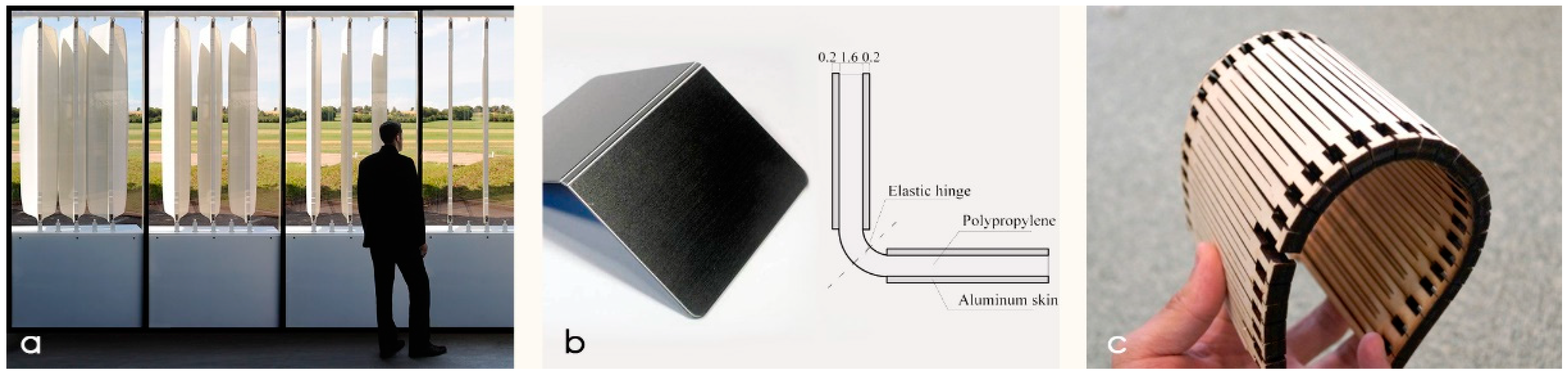
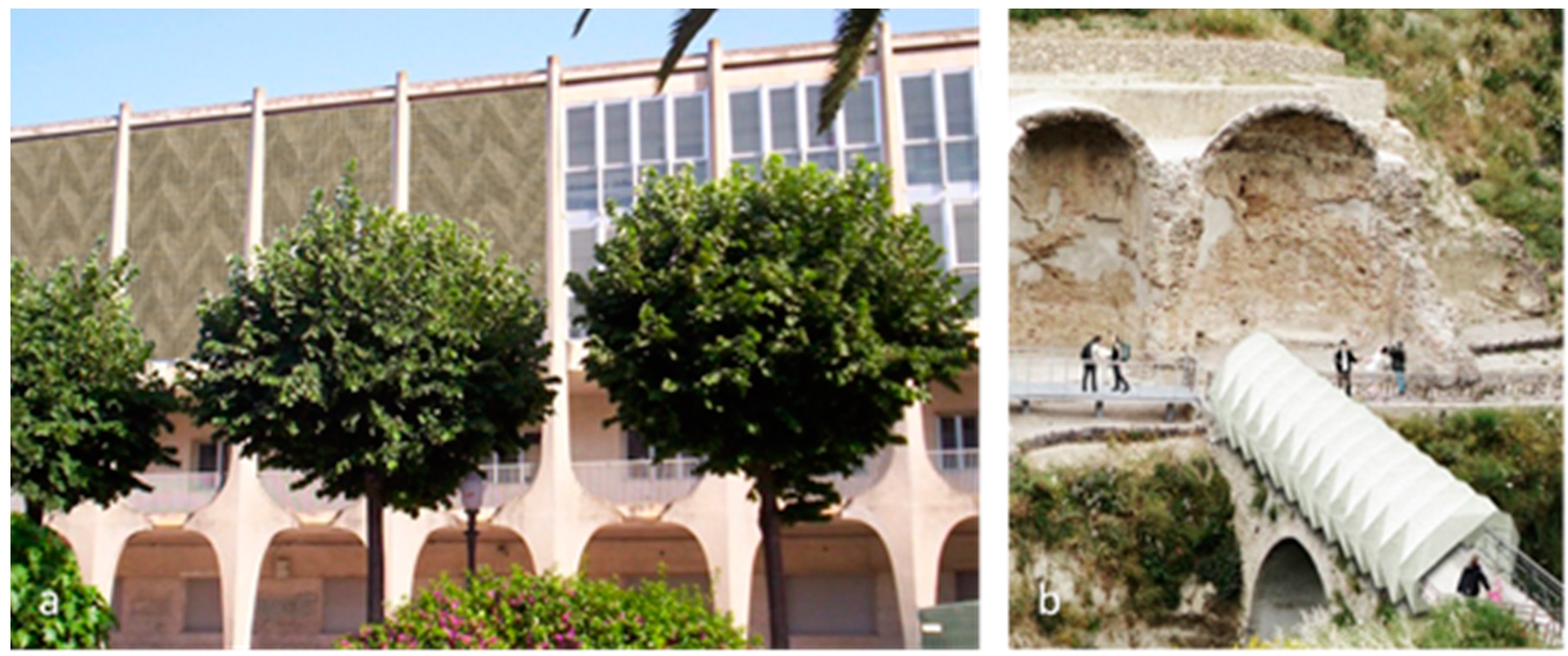
2.1. State of the Art
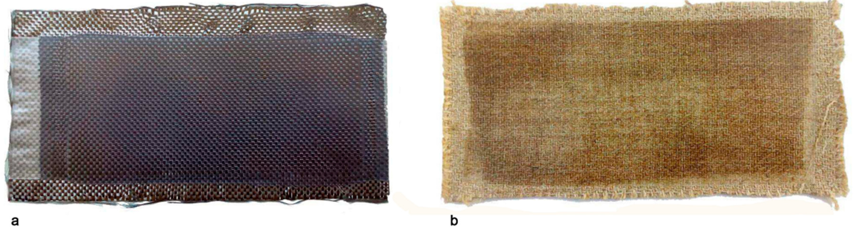
2.2. Novel Composite Material
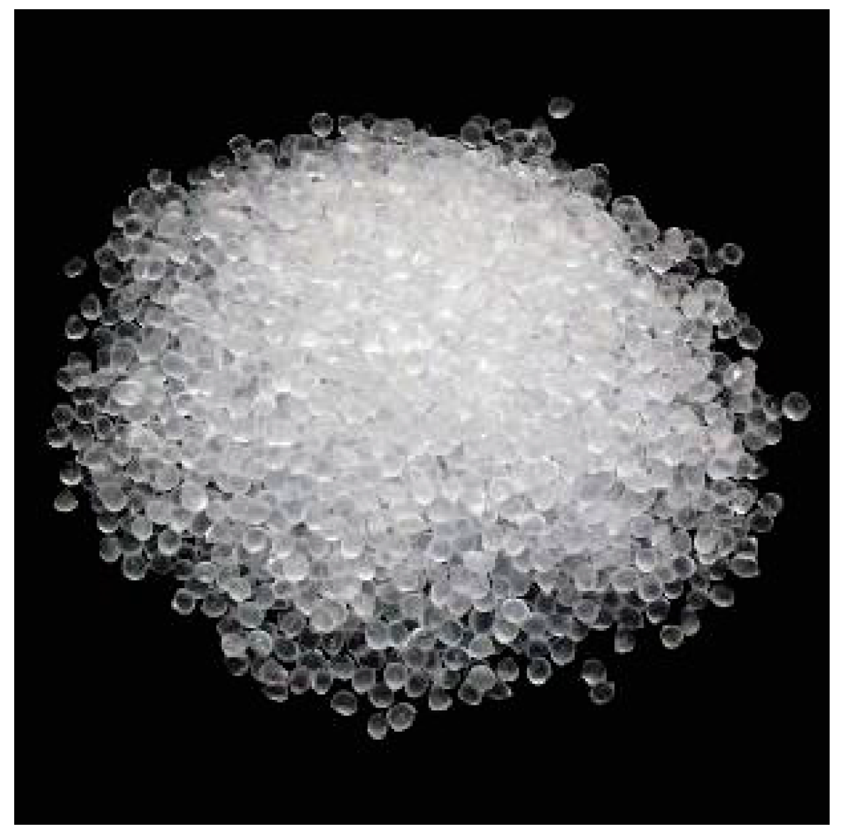
2.3. Matrix
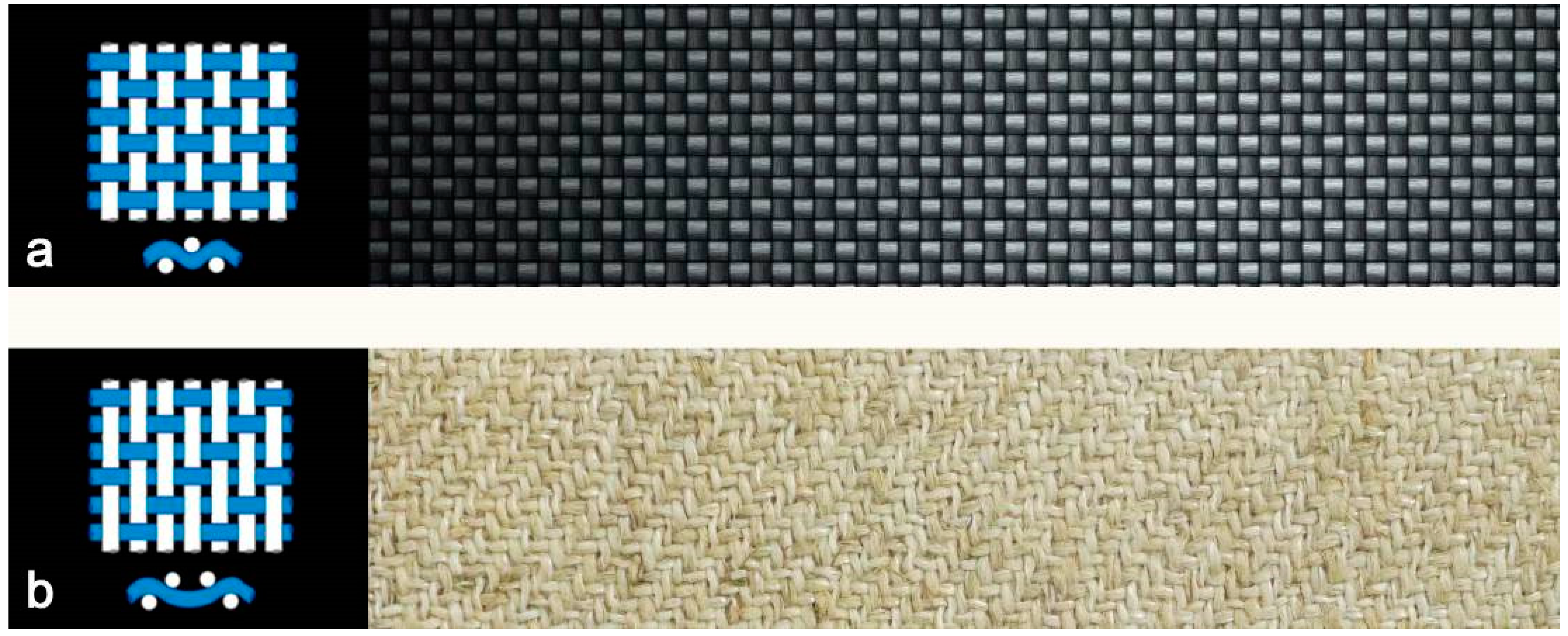
2.4. Reinforcement
3. Methods
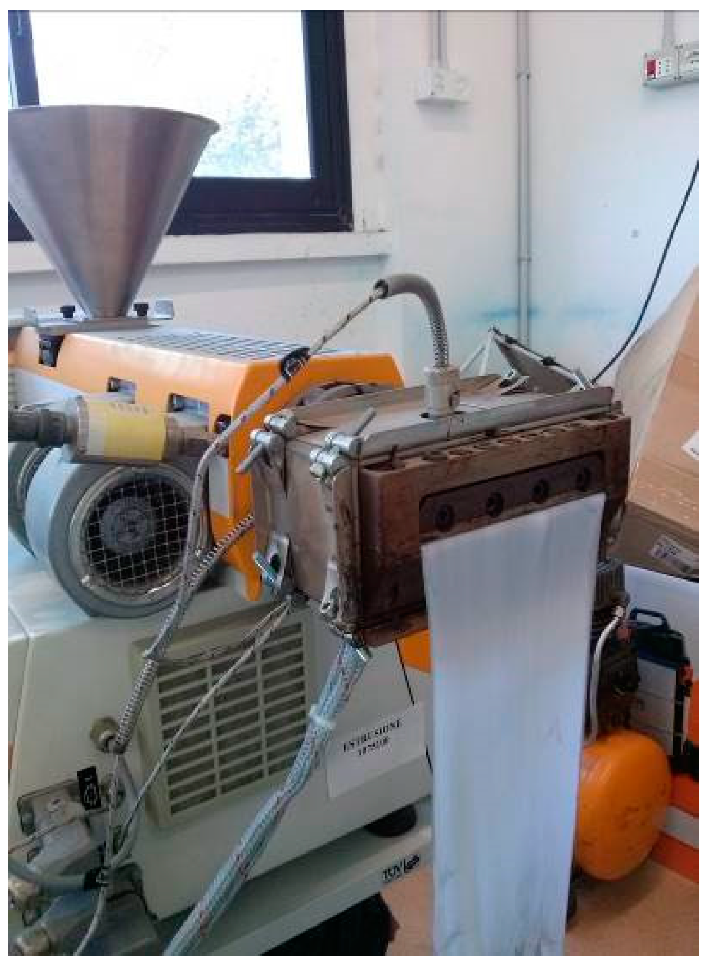
3.1. Composite Creation and Setting of Production Parameters
- Matrix-reinforcement ratio;
- Pressure;
- Times.
3.2. Preliminary Analyses and Optimization of Production Parameters
3.2.1. Visual Analysis
- The presence of air bubbles;
- The delocalization of reinforcement fibers;
- Burning of the reinforcement.
3.2.2. Tactile Analysis
3.2.3. Thickness
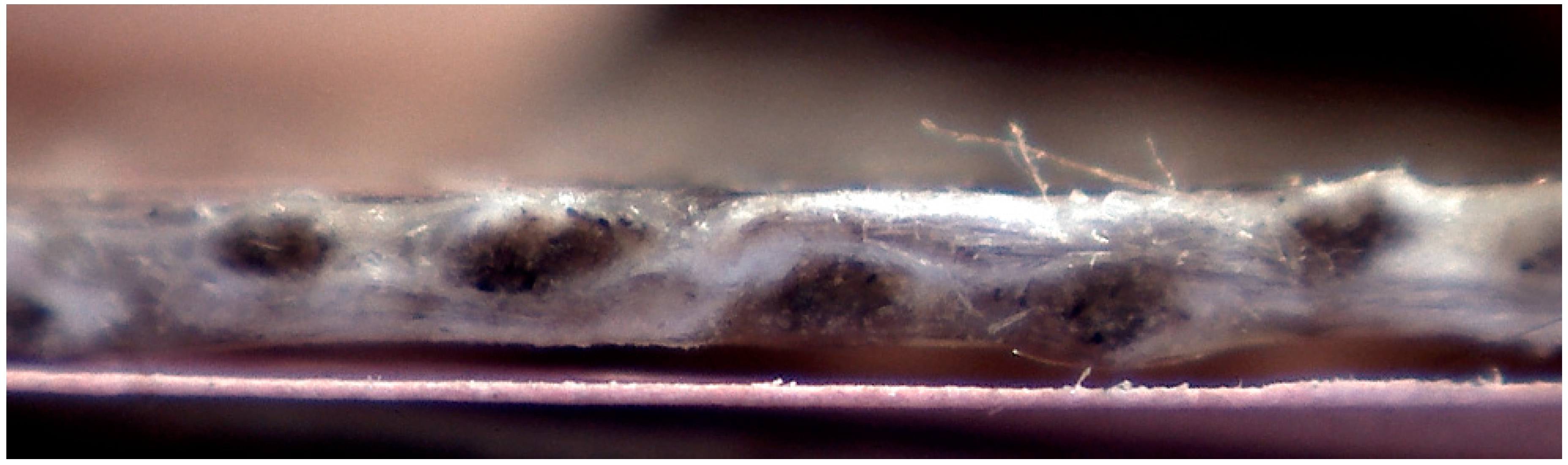
3.2.4. Cross-Section Analysis
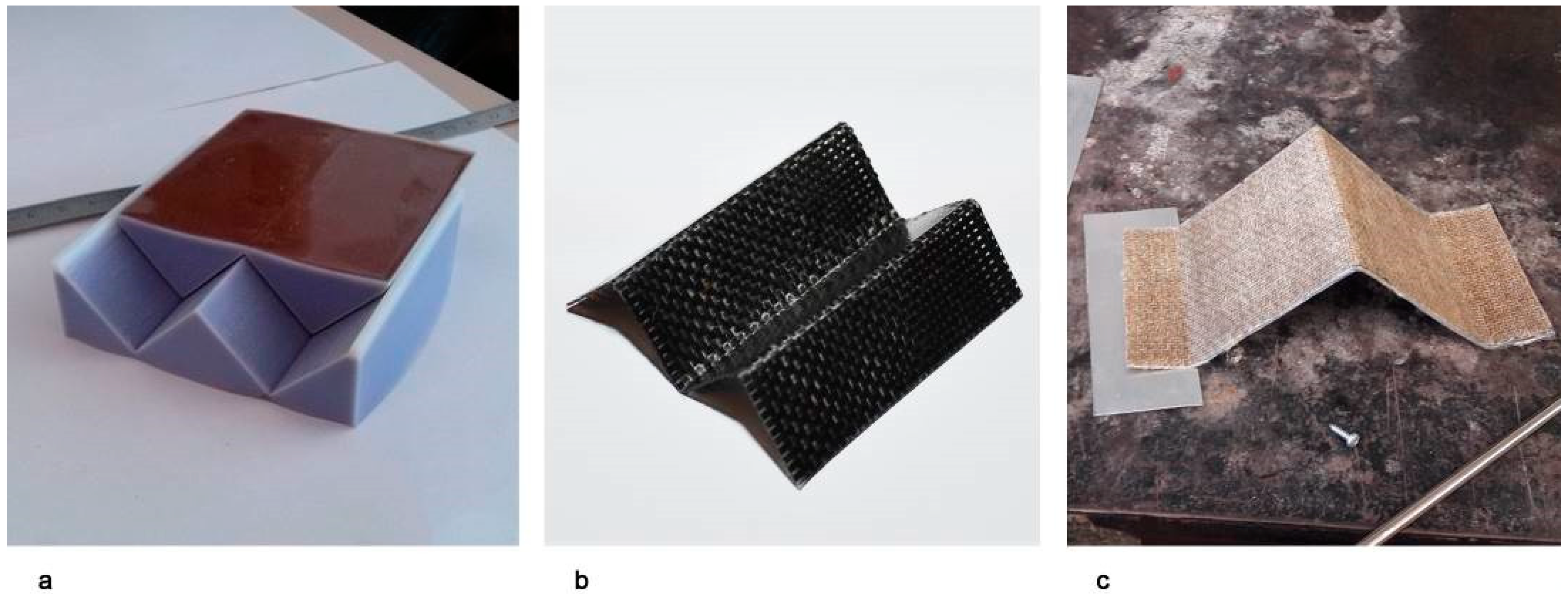
3.3. Creation of the Folding Pattern
3.4. Mechanical Characterization
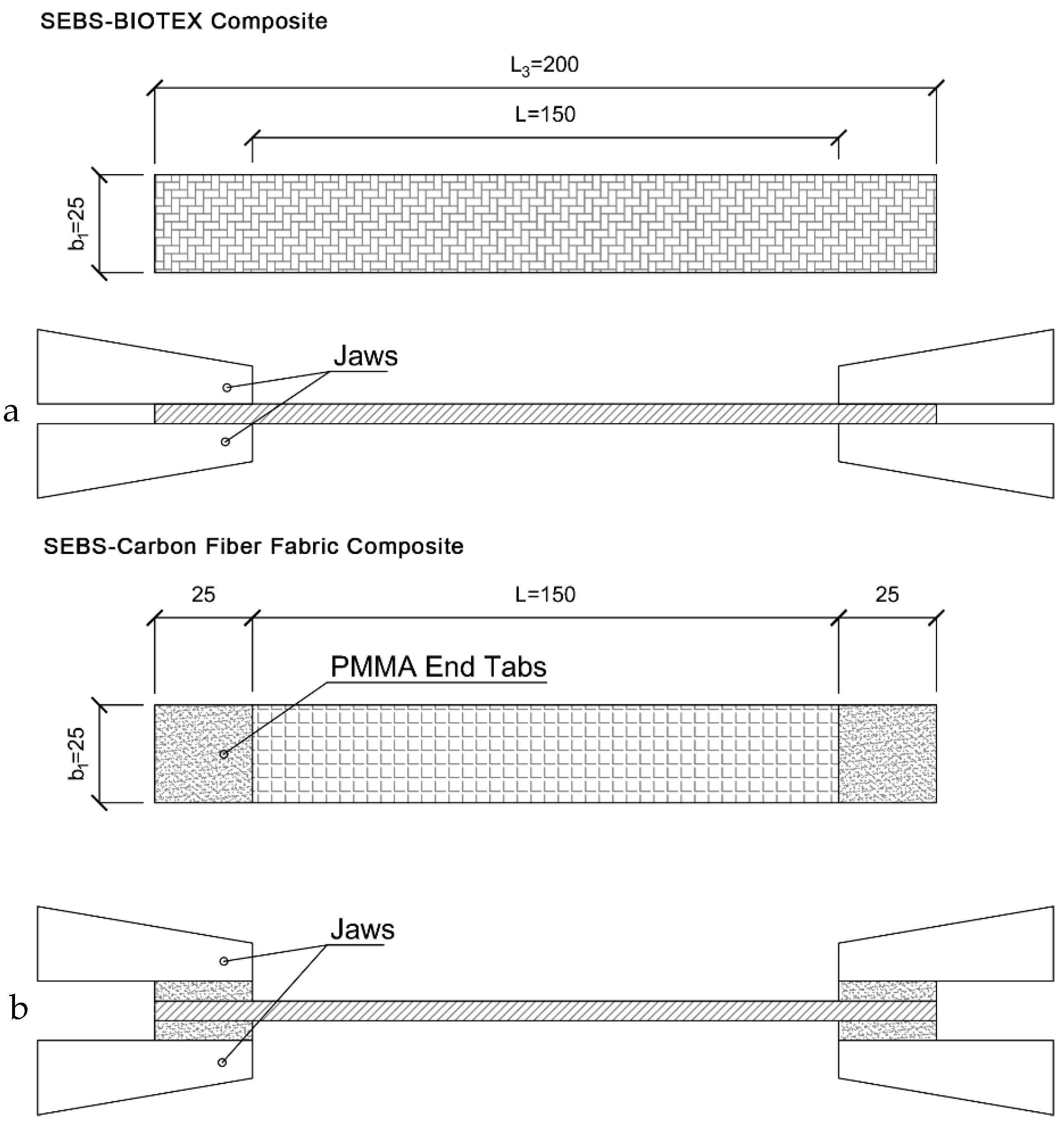
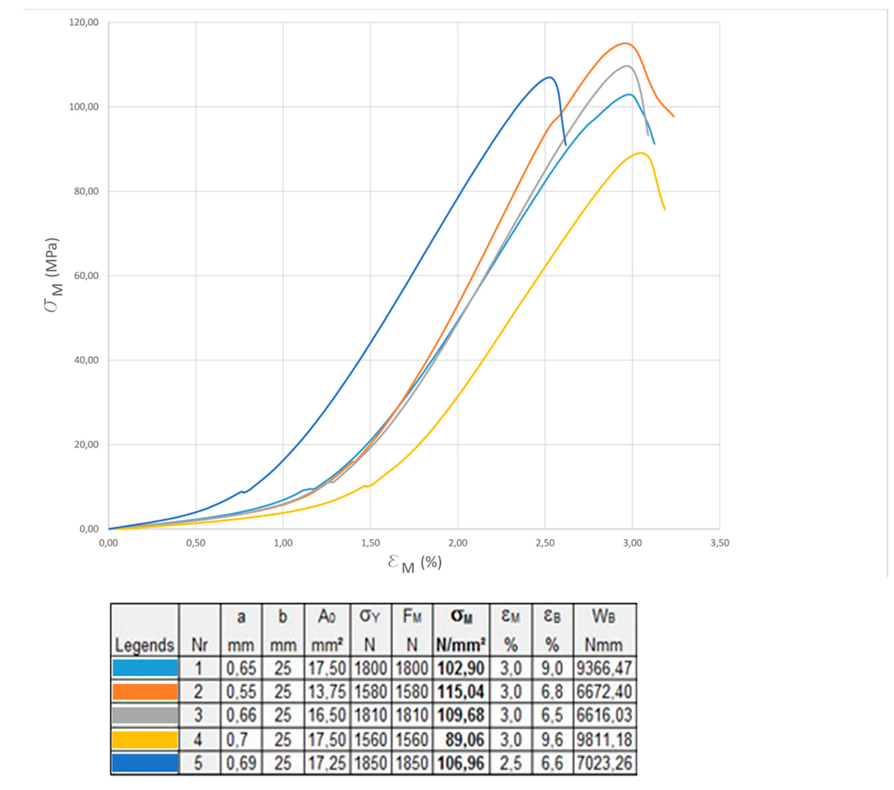
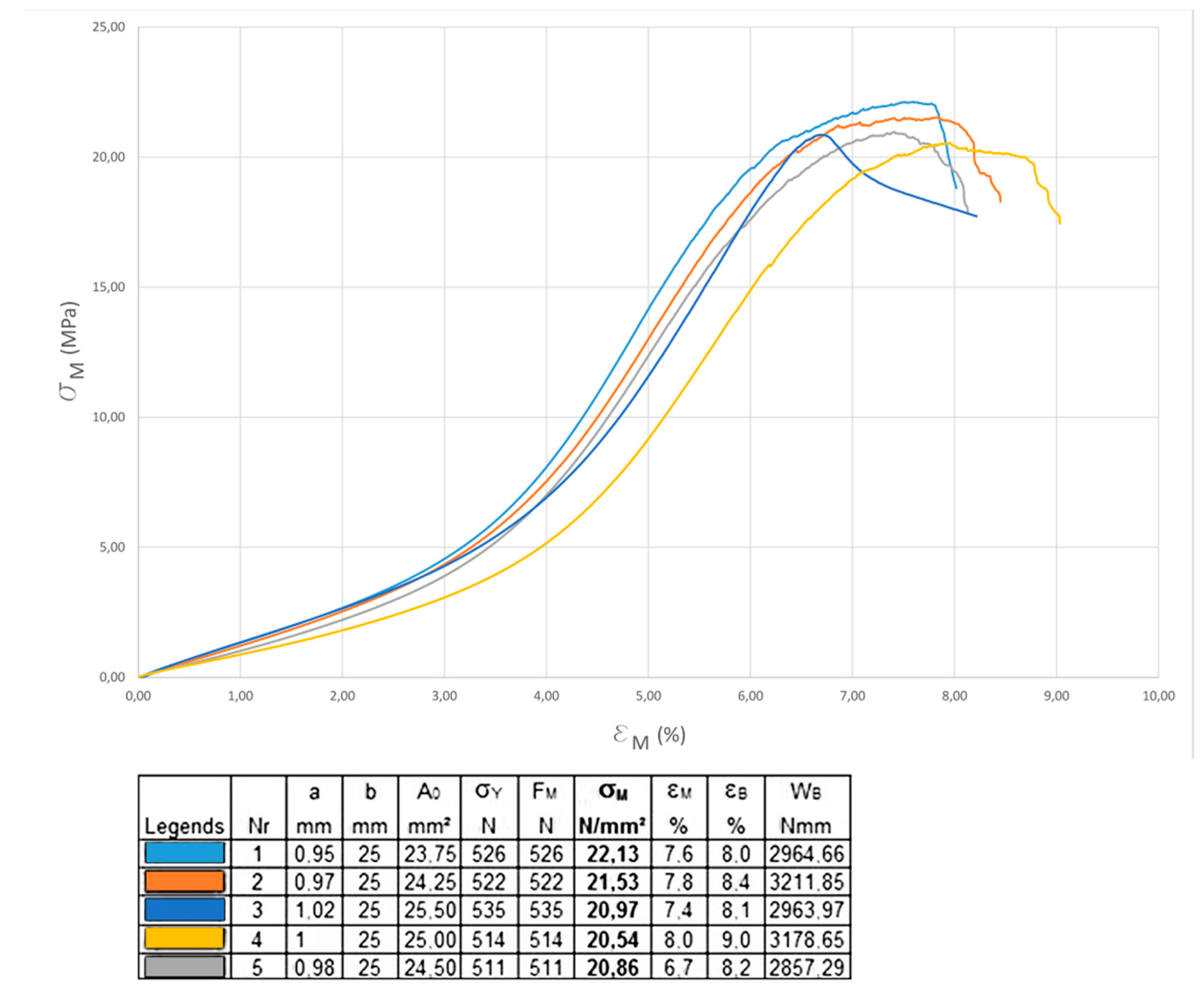
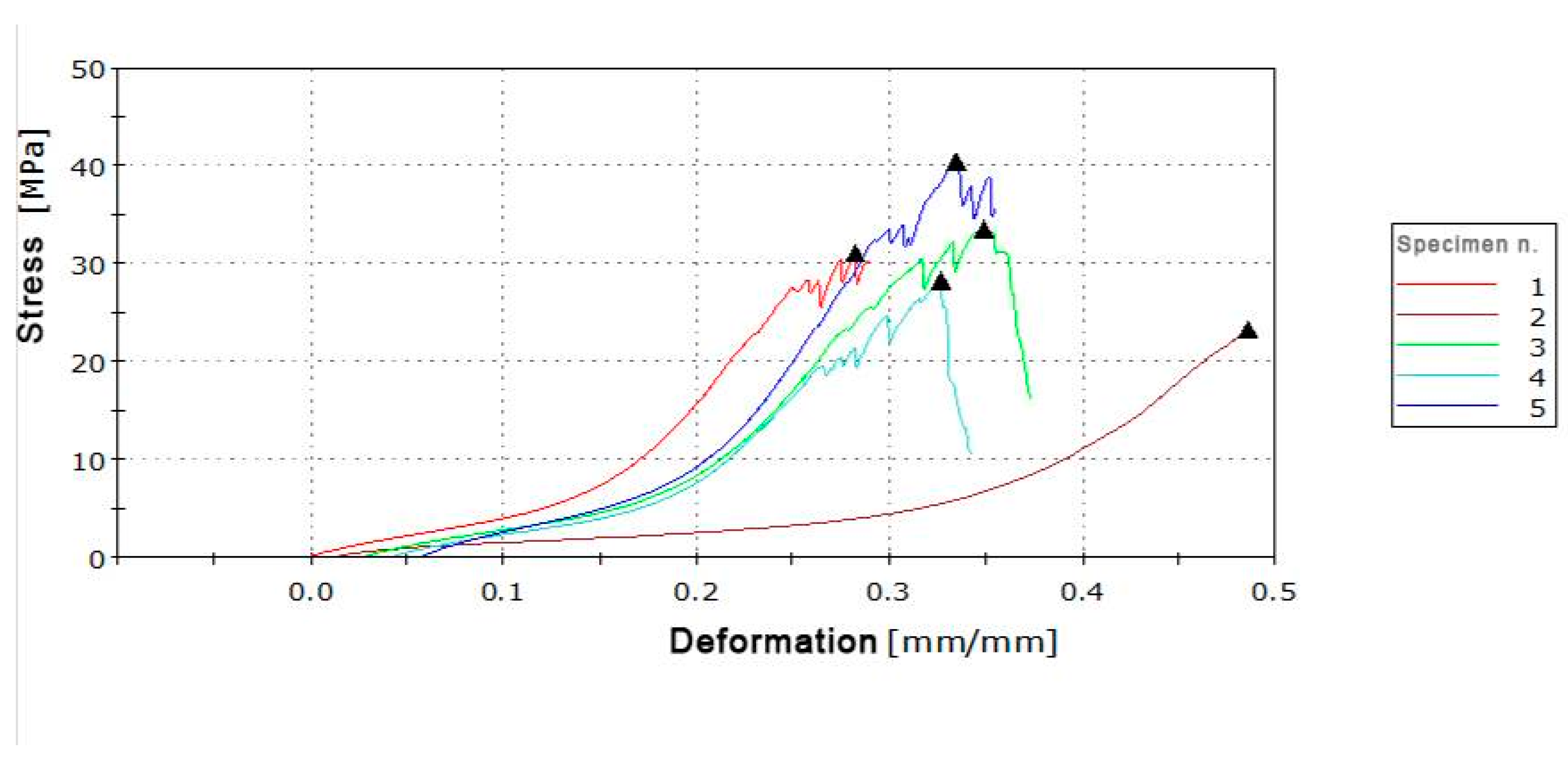
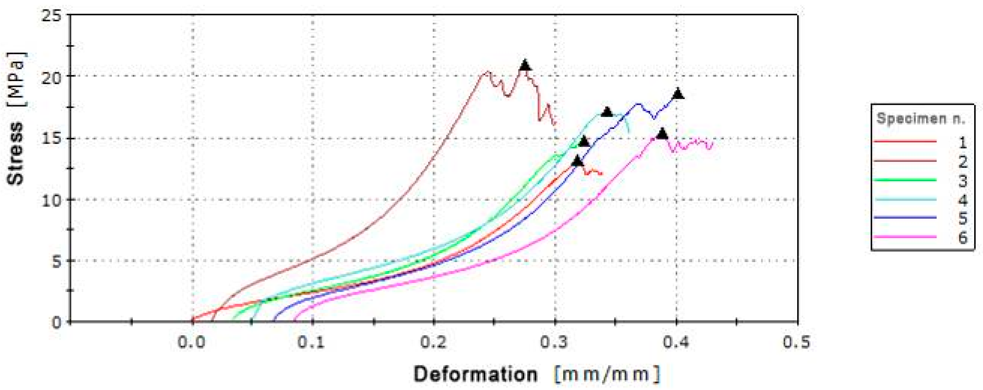
3.4.1. Uniaxial Tensile Test
3.4.2. Bias Extension Test
4. Results
4.1. Production Parameters
4.2. Creation of Folding Pattern
4.3. Mechanical Characterization
5. Discussion
- 1)
- Better recyclability;
- 2)
- Reduction of used materials;
- 3)
- Reduction of number of parts and of complexity;
- 4)
- Reduction of maintenance frequency.
6. Conclusions and Future Work
Author Contributions
Funding
Acknowledgments
Conflicts of Interest
References
- Kronenburg, R. Portable Architecture: Design and Technology; Birkhauser Verlag AG: Berlin, Germany, 2008. [Google Scholar]
- Fox, M.; Kemp, M. Interactive Architecture, 1st ed.; Princeton Architectural Press: New York, NY, USA, 2009. [Google Scholar]
- Barozzi, M.; Lienhard, J.; Zanelli, A.; Monticelli, C. The Sustainability of Adaptive Envelopes: Developments of Kinetic Architecture. Procedia Eng. 2016, 155, 275–284. [Google Scholar] [CrossRef]
- Ramzy, N.; Fayed, H. Kinetic systems in architecture: New approach for environmental control systems and context-sensitive buildings. Sustain. Cities Soc. 2011, 1, 170–177. [Google Scholar] [CrossRef]
- Loonen, R.C.G.M.; Trčka, M.; Cóstola, D.; Hensen, J.L.M. Climate adaptive building shells: State-of-the-art and future challenges. Renew. Sustain. Energy Rev. 2013, 25, 483–493. [Google Scholar] [CrossRef]
- Turrin, M.; Von Buelow, P.; Kilian, A.; Stouffs, R. Performative skins for passive climatic comfort: A parametric design process. Autom. Constr. 2012, 22, 36–50. [Google Scholar] [CrossRef]
- Thün, G.; Velikov, K.; Ripley, C.; Sauvé, L.; McGee, W. Soundspheres: Resonant chamber. Leonardo 2012, 45, 348–357. [Google Scholar]
- Soru, M. A Spatial Kinetic Structure Applied to an Active Acoustic Ceiling for a Multipurpose Theatre. Ph.D. Thesis, Delft University of Technology, Delft, The Netherlands, 2014. [Google Scholar]
- Lelieveld, C.M.J.L.; Voorbij, A.I.M.; Poelman, W.A. Adaptable Architecture. In Proceedings of the Building Stock Activation 2007: International conference on 21st century COE Program of Tokyo Metropolitan University (BSA 2007), Tokyo, Japan, 5–7 November 2007; TAIHEI Printing Co.; pp. 245–252. [Google Scholar]
- Negroponte, N. The Architecture Machine: Toward a more human environment; The MIT Press: Cambridge, MA, USA, 1970. [Google Scholar]
- Otto, F. (Ed.) IL 5–Wandelbare Dächer/Convertible Roofs. Mitteilungen des Instituts für Leichte Flächentragwerke (IL); Universität Stuttgart: Stuttgart, Germany, 1972. [Google Scholar]
- Rodonò, G.; Sapienza, V. KREO—Kinetic Responsive Envelop by Origami. TEMA Technol. Eng. Mater. Archit. 2016, 2, 42–52. [Google Scholar]
- Casale, A.; Calvano, M. House of cards. The fold for the construction of articulated surfaces. DISEGNARECON 2012, 9, 289–300. [Google Scholar]
- Salvadori, M.; Heller, R.A. Structure in Architecture; Prentice Hall: Upper Saddle River, NJ, USA, 1963. [Google Scholar]
- Casale, A.; Valenti, G.M. Architettura delle superfici piegate: Le geometrie che muovono gli origami; Edizioni Kappa: Rome, Italy, 2012. [Google Scholar]
- Peraza-Hernandez, E.A.; Hartl, D.J.; Malak, R.J., Jr.; Lagoudas, D.C. Origami-inspired active structures: A synthesis and review. Smart Mater. Struct. 2014, 23, 094001. [Google Scholar] [CrossRef]
- Reichert, S.; Menges, A.; Correa, D. Meteorosensitive architecture: Biomimetic building skins based on materially embedded and hygroscopically enabled responsiveness. CAD Comput. Aided Des. 2015, 60, 50–69. [Google Scholar] [CrossRef]
- Lelieveld, C.M.J.L. Smart Materials for the Realization of An Adaptive Building Component. Ph.D. Thesis, Faculty of Architecture, Delft University of Technology, Delft, The Netherlands, 2013. [Google Scholar]
- Lienhard, J. Bending-Active Structures: Form-Finding Strangeties Using Elastic Deformation in Static and Kinetic Systems and the Structural Potentials. Ph.D. Thesis, Universität Stuttgart, Stuttgart, Germany, 2014. [Google Scholar]
- Schleicher, S.; Lienhard, J.; Poppinga, S.; Masselter, T.; Speck, T.; Knippers, J. Adaptive façade shading systems inspired by natural elastic kinematics. In Proceedings of the International Adaptive Architecture Conference, London, UK, 3–5 March 2011. [Google Scholar]
- Curletto, G.; Gambarotta, L. Design of a composed origami-inspired deployable shelter: Modeling and technological issues. In Proceedings of the International Association for Shell and Spatial Structures (IASS) Symposium 2016, Tokyo, Japan, 26–30 September 2016. [Google Scholar]
- Ohshima, T.; Tachi, T.; Tanaka, H.; Yamaguchi, Y. Analysis and design of elastic materials formed using 2D repetitive slit pattern. In Proceedings of the International Association for Shell and Spatial Structures (IASS) Symposium 2015, Amsterdam, The Netherlands, 17–20 August 2015. [Google Scholar]
- Kronenburg, R. Introduction: The development of fabric structures in architecture. In Fabric Structures in Architecture; de Llorens, J.I., Ed.; Woodhead Publishing—Elsevier: Cambridge, MA, USA, 2015. [Google Scholar]
- Maurin, B.; Motro, R. Textile Architecture. In Flexible Compososite Matererials in Architecture Construction and Interiors; Motro, R., Ed.; Birkhauser: Basel, Switzerland, 2013; pp. 26–38. [Google Scholar]
- Pohl, G. Textiles, Polymers and Composites for Buildings; Woodhead Publishing—The Textile Institute: Cambridge, UK, 2010. [Google Scholar]
- Houtman, R. Materials used for architectural fabric structures. In Fabric Structures in Architecture; de Llorens, J.I., Ed.; Woodhead Publishing—Elsevier: Cambridge, MA, USA, 2015; pp. 101–121. [Google Scholar]
- Ku, H.; Wang, H.; Pattarachaiyakoop, N.; Trada, M. A review on the tensile properties of natural fiber reinforced polymer composites. Compos. Part B Eng. 2011, 42, 856–873. [Google Scholar] [CrossRef]
- Saheb, D.N.; Jog, J.P. Natural Fiber Polymer Composites: A Review. Adv. Polym. Technol. J. Polym. Process. Inst. 1999, 18, 351–363. [Google Scholar] [CrossRef]
- Chung, D.D.L. Processing-structure-property relationships of continuous carbon fiber polymer-matrix composites. Mater. Sci. Eng. R. Rep. 2017, 113, 1–29. [Google Scholar] [CrossRef]
- Cuomo, M.; Isola, F.; Greco, L. Simplified analysis of a generalized bias test for fabrics with two families of inextensible fibres. Z. Angew. Math. Phys. 2016, 67, 61. [Google Scholar] [CrossRef]
- Milwich, M. Types and production of textiles used for building and construction. In Textiles, Polymers and Composites for Buildings; Pohl, G., Ed.; Woodhead Publishing: Cambridge, MA, USA, 2010; pp. 13–48. [Google Scholar]
- Grobman, Y.J.; Capeluto, I.G.; Austern, G. External shading in buildings: Comparative analysis of daylighting performance in static and kinetic operation scenarios. Archit. Sci. Rev. 2017, 60, 126–136. [Google Scholar] [CrossRef]
- Kuipers, N. From static to kinetic: The potential of kinetic façades in care-hotels. aE Intecture Studio 2015, 14, 1–69. [Google Scholar]
- Alkhayyat, J. Design Strategy for Adaptive Kinetic Patterns: Creating a Generative Design for Dynamic Solar Shading Systems. Master’s Thesis, University of Salford, Manchester, UK, 2013. [Google Scholar]
- Yang, Y.; Boom, R.; Irion, B.; van Heerden, D.J.; Kuiper, P.; de Wit, H. Recycling of composite materials. Chem. Eng. Process. Process Intensif. 2011, 51, 53–68. [Google Scholar] [CrossRef]
- Schleicher, S. Bio-Inspired Compliant Mechanisms for Architectural Design: Transferring Bending and Folding Principles of Plant Leaves to Flexible Kinetic Structures. Ph.D. Thesis, Universität Stuttgart, Stuttgart, Germany, 2016. [Google Scholar]
- Sapienza, V.; Rodonò, G. Kinetic Architecture and Foldable Surface. Athens J. Archit. 2016, 2, 223–235. [Google Scholar] [CrossRef]
- Schenk, M.; Guest, S.D. Geometry of Miura-folded metamaterials. Proc. Natl. Acad. Sci. USA 2013, 110, 3276–3281. [Google Scholar] [CrossRef] [PubMed]


| Specimen | Layer | Weight (g) | Pressure (MPa) | Time of Pressure (s) | Thickness (mm) | Medium Thickness (mm) | ||||||
|---|---|---|---|---|---|---|---|---|---|---|---|---|
| Matrix | Reinforcement | Matrix | Reinforcement | |||||||||
| S4C1_1 | 4 sheets of SEBS 0.5 mm | 1 sheet of carbon fiber fabric | x | x | 1 | x | 2.15 | 2.18 | 1.95 | 2.20 | 2.02 | 2.10 |
| S4C1_2 | x | x | 2 | x | 1.95 | 1.83 | 2.07 | 2.10 | 1.93 | 1.98 | ||
| S4C1_3 | x | x | 3 | x | 1.92 | 1.80 | 1.84 | 1.89 | 1.75 | 1.84 | ||
| S4C1_4 | x | x | 4 | x | 1.82 | 1.72 | 1.70 | 1.72 | 1.60 | 1.71 | ||
| note | _For a better control of the composite it is appropriate to record the weights of the materials before thermoforming them. _Minimize the thickness to optimize the performance of the material: more reinforcement and less matrix. | |||||||||||
| S4C2_4 | 4 sheets of SEBS 0.5 mm | 2 sheet of carbon fiber fabric | 23.22 | 7.95 | 4 | x | 1.13 | 1.12 | 1.13 | 1.20 | 1.15 | 1.15 |
| S4C2_6 | 22.82 | 7.22 | 6 | x | 0.94 | 0.97 | 1.03 | 1.08 | 1.00 | 1.00 | ||
| S4C2_18 | 23.46 | 7.68 | 18 | x | 0.66 | 0.65 | 0.70 | 0.76 | 0.71 | 0.70 | ||
| note | _The pressure time affects the result: it should be recorded. | |||||||||||
| S4C2_20_90 | 4 sheets of SEBS 0.5 mm | 2 sheet of carbon fiber fabric | 23.36 | 6.95 | 20 | 90 | 0.65 | 0.66 | 0.61 | 0.66 | 0.64 | 0.64 |
| S4C2_25_90 | 16.75 | 7.88 | 25 | 90 | 0.63 | 0.56 | 0.50 | 0.63 | 0.60 | 0.58 | ||
| S3C2_5_60 | 3 sheets of SEBS 0.5 mm | 2 sheet of carbon fiber fabric | 16.54 | 5.78 | 5 | 60 | 0.62 | 0.60 | 0.64 | 0.63 | 0.68 | 0.58 |
| S3C2_15_60 | 15 | 60 | ||||||||||
| S3C2_5_150 | 16.35 | 6.24 | 5 | 150 | ||||||||
| S3C2_10_60 | 10 | 60 | ||||||||||
| S3C2_1_180 | 39.7 | 5.97 | 1 | 180 | ||||||||
| S3C2_5_180 | 5 | 180 | ||||||||||
| S3C2_10_60 | 10 | 60 | ||||||||||
| note | _Testing with SEBS with lower surface development than fibers to try to reduce the amount of polymer. _SEBS “pulls the fibers” and dislocates it. does not reduce the thickness. Weak samples. _It is advisable to program other tests with SEBS and reinforcement of the same size. | |||||||||||
| S3C2_2_90 | 3 sheets of SEBS 0.17 mm | 2 sheet of carbon fiber fabric | 5.8 | 4.74 | 2 | 90 | ||||||
| note | _A preliminary analysis to the touch showed surface roughness. We replace baking paper with Teflon sheets for the detachment from the press. _Then visual analysis and analysis to the touch show more regular and uniform surfaces. | |||||||||||
| S2C1_0.2_120 | 2 sheets of SEBS 0.17 mm | 1 sheet of carbon fiber fabric | 5.28 | 3.2 | 0.2 | 60 | ||||||
| S2C1_0.5_120 | 5.25 | 3.44 | 0.5 | 120 | ||||||||
| S2C1_1_120 | 5.4 | 3.3 | 1 | 60 | ||||||||
| S2C1_1_120 | 5.2 | 3.45 | 1 | 120 | ||||||||
| S2C1_4_120 | 5.4 | 3.45 | 4 | 120 | ||||||||
| S2C1_5_120 | 5.6 | 3.38 | 5 | 120 | 0.58 | 0.58 | 0.63 | 0.61 | 0.61 | 0.60 | ||
| note | _At a pressure of 5 MPa, a more uniform distribution of SEBS is obtained. | |||||||||||
| Specimen | Layer | Weight (g) | Pressure (MPa) | Time of Pressure (s) | Thickness (mm) | Medium Thickness (mm) | ||||||
|---|---|---|---|---|---|---|---|---|---|---|---|---|
| Matrix | Reinforcement | Matrix | Reinforcement | |||||||||
| S4B1_1 | 4 sheets of SEBS 0.5 mm | 1 sheet of Biotex | x | x | 1 | x | 2.25 | 2.18 | 2.22 | 2.30 | 2.17 | 2.22 |
| S4B1_2 | x | x | 2 | x | 2.05 | 2.12 | 1.74 | 1.89 | 1.92 | 1.94 | ||
| S4B1_3 | x | x | 3 | x | 2.18 | 2.14 | 2.00 | 2.15 | 2.07 | 2.11 | ||
| S4B1_4 | x | x | 4 | x | 1.73 | 1.89 | 1.87 | 2.18 | 2.24 | 1.98 | ||
| note | _For a better control of the composite it is appropriate to record the weights of the materials before thermoforming them. _Minimize the thickness to optimize the performance of the material: more reinforcement and less matrix. | |||||||||||
| S2B1_2_60 | 2 sheet of SEBS 0.17 mm | 1 sheet of Biotex | 4.54 | 5.4 | 2 | 60 | 0.78 | 0.74 | 0.73 | 0.70 | 0.78 | 0.75 |
| note | _A preliminary analysis to the touch showed surface roughness. To ensure a better separation from the press machine. we replace baking paper with Teflon sheets. _Then visual analysis and analysis to the touch show more regular and uniform surfaces. | |||||||||||
| S2B1_2_60 | 2 sheet of SEBS 0.17 mm | 1 sheet of Biotex | 4.62 | 5.8 | 2 | 60 | 0.77 | 0.77 | 0.75 | 0.78 | 0.77 | 0.77 |
| S2B1_1_90 | 4.69 | 5.3 | 1 | 90 | 0.77 | 0.76 | 0.75 | 0.71 | 0.77 | 0.75 | ||
| S2B1_0.5_120 | 4.71 | 5.58 | 0.5 | 120 | 0.98 | 1.08 | 0.99 | 1.02 | ||||
| note | _The visual analysis shows a non-uniform distribution of the SEBS with many air bubbles that may be related to the presence of water in the fabric. _As a possible solution we have ironed the fabric in the press at 180 °C for 90 s at 2 MPa. pressed slowly to not move the fibers. | |||||||||||
| S2B1D_0.5_120 | 2 sheet of SEBS 0.17 mm | 1 sheet of Biotex | 5.54 | 6.25 | 0.5 | 120 | 0.92 | 1.04 | 0.98 | 0.98 | ||
| note | _The visual analysis of the sample shows the absence of air bubbles. _The sample exceeds the visual and tactile analysis and it is subjected to Cross section analysis: good matrix-reinforcement interface. | |||||||||||
| Layer | Dimensions (mm) | Weight (g) | Pressure (MPa) | Time of Pressure (s) | Thickness (mm) | Medium Thickness (mm) | ||||
|---|---|---|---|---|---|---|---|---|---|---|
| Matrix | Reinf. | Matrix | Reinf. | Matrix | Reinf. | |||||
| SEBS–Carbon fiber fabric | 2 sheets | 1 sheet | 70 × 200 | 5.35 | 3.40 | 5.0 | 120 | 0.170 | 0.290 ± 0.44 | 0.600 |
| SEBS–Biotex | 2 sheets | 1 sheet | 70 × 200 | 5.35 | 6.30 | 0.5 | 120 | 0.170 | 0.450−0.800 | 0.980 |
| Specimen No. | E (MPa) |
|---|---|
| 1 | 134.3 |
| 2 | 132.3 |
| 3 | 119.5 |
| 4 | 93.1 |
| 5 | 130.3 |
| EM | 129.1 |
| Specimen No. | E (MPa) |
|---|---|
| 1 | 134.3 |
| 2 | 132.3 |
| 3 | 119.5 |
| 4 | 93.1 |
| 5 | 130.3 |
| EM | 129.1 |
| Specimen No. | G (MPa) |
|---|---|
| 1 | 5.6 |
| 2 | --- |
| 3 | 4.8 |
| 4 | 4.7 |
| 5 | 7.4 |
| GM | 5.6 |
| Specimen No. | G (MPa) |
|---|---|
| 1 | 3.2 |
| 2 | --- |
| 3 | 3.8 |
| 4 | 4.3 |
| 5 | 4.2 |
| 6 | 3.5 |
| GM | 3.8 |
| Composite | Maximum Stress | Weight |
|---|---|---|
| Cotton/polyester blend | 1000–2500 N/50 mm | 350–520 g/m2 |
| SEBS–Biotex | 21.20 N/mm2 (≈1000 N/50 mm) | 720 g/m2 |
| PTFE–Fiber glass fabric | 3500–8000 N/50 mm | 800–1500 g/m2 |
| SEBS–Carbon fiber fabric | 104.73 N/mm2 (≈3100 N/50 mm) | 550 g/m2 |
© 2019 by the authors. Licensee MDPI, Basel, Switzerland. This article is an open access article distributed under the terms and conditions of the Creative Commons Attribution (CC BY) license (http://creativecommons.org/licenses/by/4.0/).
Share and Cite
Rodonò, G.; Sapienza, V.; Recca, G.; Carbone, D.C. A Novel Composite Material for Foldable Building Envelopes. Sustainability 2019, 11, 4684. https://doi.org/10.3390/su11174684
Rodonò G, Sapienza V, Recca G, Carbone DC. A Novel Composite Material for Foldable Building Envelopes. Sustainability. 2019; 11(17):4684. https://doi.org/10.3390/su11174684
Chicago/Turabian StyleRodonò, Gianluca, Vincenzo Sapienza, Giuseppe Recca, and Domenico Carmelo Carbone. 2019. "A Novel Composite Material for Foldable Building Envelopes" Sustainability 11, no. 17: 4684. https://doi.org/10.3390/su11174684
APA StyleRodonò, G., Sapienza, V., Recca, G., & Carbone, D. C. (2019). A Novel Composite Material for Foldable Building Envelopes. Sustainability, 11(17), 4684. https://doi.org/10.3390/su11174684