Article

Stability Charts for Sustainable Infrastructure: Collapse Loads of Footings on Sandy Soil with Voids

1
Department of Civil Engineering, University of Seoul, Seoul 02504, Korea
2
Department of Civil Engineering, Dongshin University, Naju 58245, Korea
*
Author to whom correspondence should be addressed.
Sustainability 2019, 11(14), 3966; https://doi.org/10.3390/su11143966
Submission received: 28 May 2019 / Revised: 18 July 2019 / Accepted: 19 July 2019 / Published: 22 July 2019
(This article belongs to the Section Sustainable Engineering and Science)

Abstract

:
The presence of underground voids in regions suitable for sustainable development can adversely affect the stability of the overlying infrastructures. In this paper, the collapse loads of strip rigid footings resting on sand with single and double continuous voids are determined for a frictional Mohr-Coulomb material following the non-associated flow rule. For use by practitioners, design charts are proposed to evaluate the well-known bearing capacity factor Nγ as a function of the dimensionless parameters related to the vertical and horizontal void distances from the footing, void shape, and spacing between the two voids, as well as the soil friction angle. The computational result compares quite favorably with the available theoretical and numerical solutions. The failure mechanism is broadly discussed based on the pattern of soil displacement around the footing and void.

1. Introduction

Civil engineering design and construction processes have emphasized the safety and serviceability of infrastructure. In recent years, most infrastructure is planned not only to endure external and internal disturbance without significant loss of integrity and functionality over time, but also to improve sustainability elements in every stage of the design and construction [1]. Meanwhile, the robustness of infrastructure is tied to societal vulnerability and resilience. As an example, the formation of subsurface voids, leading to ground and sinkhole subsidence, represents a risk of infrastructure performance, which can be potentially detrimental to the safety of humans as well as the environment and communities.
Footings are often placed on ground with voids that are either undetected before construction or formed after construction. The underground voids typically occur as a result of the dissolution of soluble rocks, the dynamic loading caused by construction and mining activities, the existence of nearby leaking pipelines, and the subsidence of poorly compacted trench backfill [2]. There are studies on the stability of footings located above voids [3,4,5,6,7,8,9,10] and footings on geosynthetic-reinforced soil with voids [11,12,13,14,15,16,17]. In the literature, researchers investigated the effect of the shape, size, location, and number of voids, as well as the type, dimension, number, and configuration of the geosynthetics. Lai et al. [18] further studied the bearing capacity of low geosynthetic-reinforced embankments overlying voids.
The bearing capacity of a centrally and vertically loaded strip footing is usually determined by the formula proposed by Terzaghi [19], assuming that the shear strength of soil can be represented by a linear Mohr-Coulomb failure envelop:
q u = c N c + q D N q + 1 2 γ B N γ
where, qu is the ultimate bearing pressure, c is the cohesion of the soil, q is the surface surcharge, D is the depth of embedment, γ is the unit weight of soil, B is the width of the footing, and Nc, Nq, and Nγ are the non-dimensional bearing capacity factors related to cohesion, surcharge, and soil weight, which are all functions of the soil friction angle φ. Such additivity of the individual contributions simplifies the mathematical analysis substantially and hence this solution is widely used in engineering practice. However, Equation (1) is not strictly correct because soil response in the plastic range is non-linear, implying that plastic theory does not satisfy the superposition principle valid in elasticity [20]. As demonstrated in Bolton and Lau [21], Equation (1) yields conservative estimates of the ultimate bearing capacity.
The bearing capacity factors Nc and Nq are solved analytically using the method of characteristics (also called slip-line method) assuming that the soil follows an associated flow rule (i.e., the dilation angle ψ equal to φ) [22]. It is generally expected that the method enables accurate prediction, although the closed-form solution can be obtained for a weightless soil. In contrast, the evaluation of Nγ requires that the soil weight be taken into account. In this case, the stress characteristic field may be constructed numerically and therefore the solution is typically found using the finite element method (FEM) and finite difference method (FDM) [23,24,25,26].
For a strip footing on the surface of sand (for which both surcharge and soil cohesion are zero), the bearing capacity formula of Equation (1) reduces to
q u = 1 2 γ B N γ
It is noted that the term sand implies the granular material (particulate network) and the long-term condition that requires effective stress analysis, which is applicable to geotechnical analysis. A number of approximate solutions for Nγ have been reported in literature and a comprehensive overview is given by Diaz-Segura [27]. Consideration is given to the effects of footing geometry (e.g., strip, rectangular, square, circular, and conical footings), footing roughness (e.g., footing-soil interface), soil properties (e.g., friction angle, relative density, and anisotropy), stress level (e.g., mean effective stress and intermediate principal stress) and non-associativity (i.e., the dilation angle ψ being less than φ) [28,29,30,31,32,33,34,35].
This study presents a comprehensive set of Nγ values for strip footings resting on sand with a variety of void numbers, shapes, and locations, as well as a range of friction angles. The technique used involves application of the FEM. Previously, the FEM was applied to analyze the yield pressure of cohesive-frictional soils with voids by several researchers [3,4,36,37]. Recently, Lee et al. [38] calculated the finite element solutions for the Nc value of strip footings on clay with voids. Furthermore, the limit analysis theory was employed to study the bearing capacity of strip footings above voids in two-layered clays and rock mass by Xiao et al. [39,40]. Zhou et al. [10] extended the limit analysis to evaluate the collapse load of the footing-above-void system by using the discontinuity layout optimization (DLO) technique. However, no thorough analysis of the drained bearing capacity of strip footings on sand has been performed and the corresponding Nγ values are not available in literature.

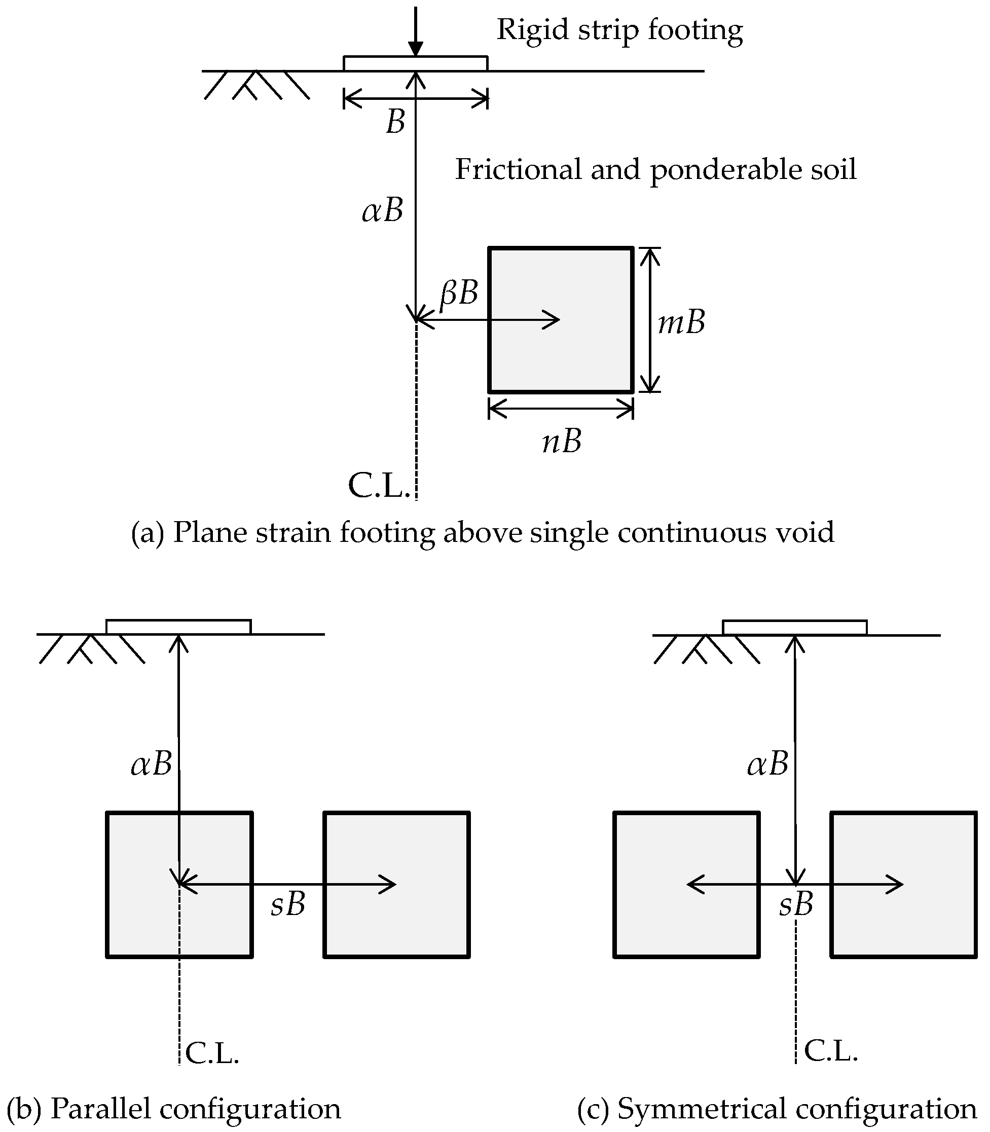
2. Problem Statement

Figure 1 illustrates the geometries and parameters of the problem analyzed. A rigid strip footing of width B is placed on the horizontal surface of an isotropic homogenous soil of friction angle φ and unit weight γ. A static vertical load is imposed at the centerline of the footing. By considering the case of zero surcharge and zero soil cohesion, the bearing capacity factor Nγ can be computed directly using finite element analysis. The bearing capacity of the footing above underground openings is influenced by the size, shape, location, and number of voids. Kiyosumi et al. [7] investigated the dimension of voids in calcareous sediments and revealed that the size of voids ranges from less than 1 to as large as about 10 m. A square-shaped void is adopted in this study, as the influence of void shape can be neglected [3]. As shown in Figure 1a, the shape and location of the void are quantified in terms of dimensionless parameters, i.e., m, n, α, and β. The parameters m and n represent the void height and width normalized by the footing width B. The parameters α and β designate the relative vertical and horizontal distances from the centerline of the footing to the center of the void normalized by B. Figure 1b,c show the parallel and symmetrical configurations of two voids, respectively. It is assumed that the two voids have the same size and shape at a given depth. The two voids are separated by the parameter s, defined as the horizontal distance between two void centers normalized by B.

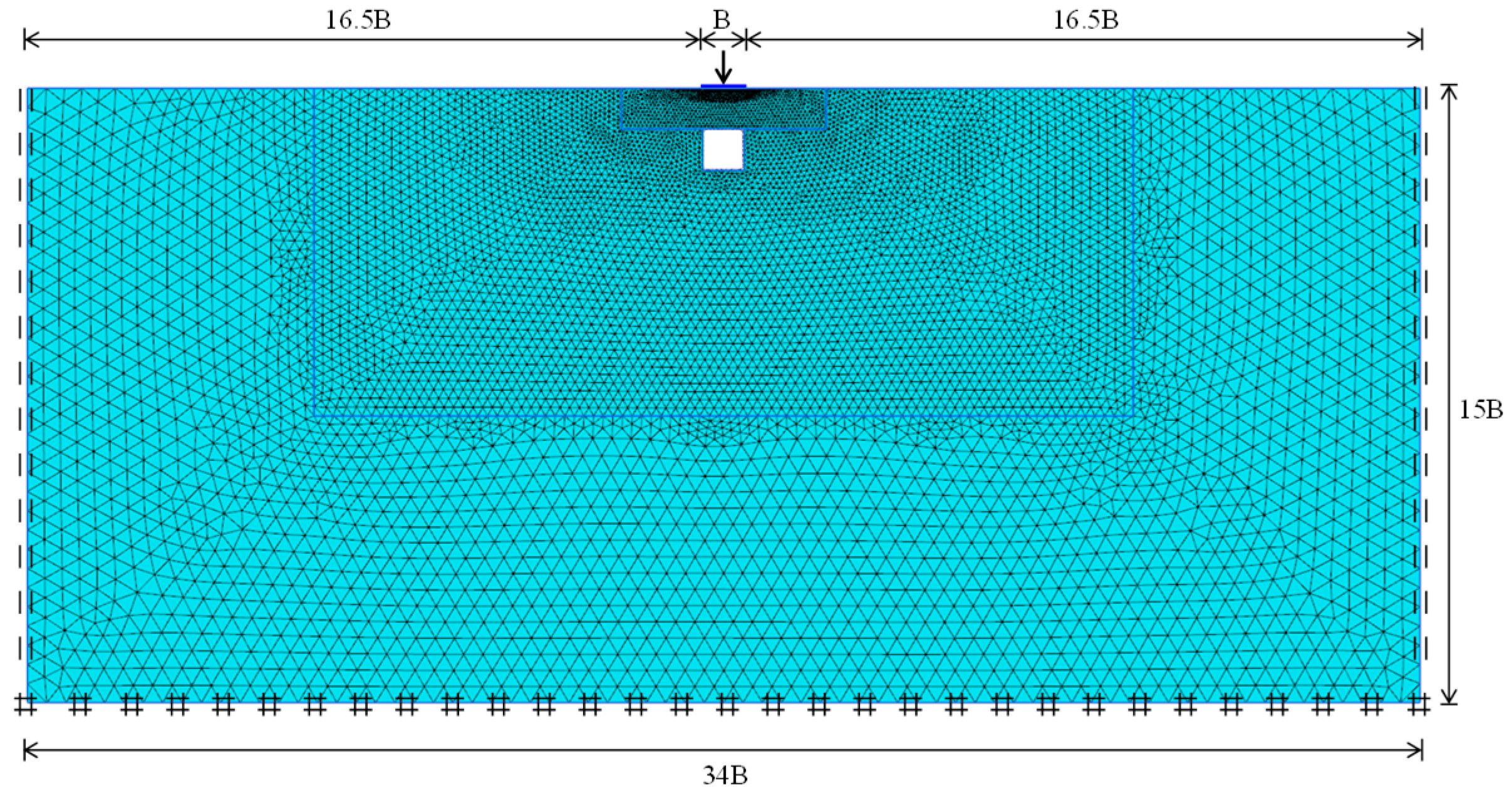
3. Finite Element Model

A series of small strain finite element analyses was carried out using the commercial software PLAXIS 2D version 2012. The soil was modeled with fifteen-node triangular elements and the footing was modeled with six-node triangular plate elements. Figure 2 shows a schematic of the boundary conditions and finite element mesh used in this study. The external boundaries are positioned 16.5B laterally from the edge of the footing and 15B beneath the footing. In the arrangement, the boundary effect on the estimation of the failure load can be neglected. The vertical boundary is restrained against horizontal displacement, and the bottom boundary is restrained against displacement in the vertical and horizontal directions. Small elements were introduced in the area adjacent to the footing to enhance the accuracy of the numerical results. The underside of the footing was simulated as perfectly rough by specifying a tied contact constraint at the soil-footing interface.
Soil is idealized as an elastic-perfectly plastic material obeying the linear Mohr-Coulomb yield criterion. The friction angle φ is varied from 20 to 40 in 10 increments. Since it is well known that the dilatancy angle ψ is considerably less than the friction angle for real soils, the analyses with a non-associated flow rule were undertaken using realistic pairs of φ and ψ: φ = 30 and ψ = 0, φ = 30 and ψ = 0, φ = 40 and ψ = 12. This set is consistent with predictions by Bolton [41] for the critical state of sands. As adopted by Diaz-Segura [27] for sands, the Young’s modulus and Poisson’s ratio were set to Es = 40 MPa and ν = 0.3, respectively. The unit weight was assumed to be γ = 20 kN/m3. However, the selection of γ is immaterial because the Nγ value can be normalized almost perfectly with respect to γ [34]. The coefficient of earth pressure at rest K0 was taken as unity to calculate the initial stresses with self-weight of the soil.
Footing was modeled as a non-porous linear elastic material with width B = 2 m and thickness t = 1 m. The Young’s modulus of the footing was set to be Ec = 30 GPa, which is three orders of magnitude greater than that of the soil, implying that the footing is defined as a rigid body. The footing was subjected to successive incremental load up to the collapse load. The bearing capacity factor Nγ stemming from the unit weight and friction angle of the soil is expressed by
N γ = Q u 0.5 γ B 2
where, Qu is the magnitude of the collapse load per unit length. Other parameters have been defined previously.
The examples of the evolution of the bearing capacity factor Nγ with footing displacement are shown in Figure 3. The initial settlement or stiffness is independent on the friction angle, as expected. The Nγ value for φ = 30 is determined to be 6.7, which is approximately 7.2 times higher than that for φ = 20. The numerical oscillations in the load-displacement curves are observed and the magnitude of oscillations increases with an increase in the friction angle φ. Such oscillations were found in other studies involving a Mohr-Coulomb constitutive law with the non-associated flow rule [24,28,42]. It is attributed to the apparent softening exhibited in shear bands by a Mohr-Coulomb material with ψ < φ, even when strength properties are constant. As pointed out by Drescher and Detournay [43], the apparent strain softening is a consequence of the rotation of the principal stress axes as strains are localized inside the shear bands. It is noteworthy that the oscillation displayed in the load-displacement response does not undermine the validity of the current finite element analyses, but the only problem is the selection of the limit load [42]. In this study, the collapse load is taken as the maximum load value of the load-displacement behavior obtained from the present analysis.

4. Results and Discussion
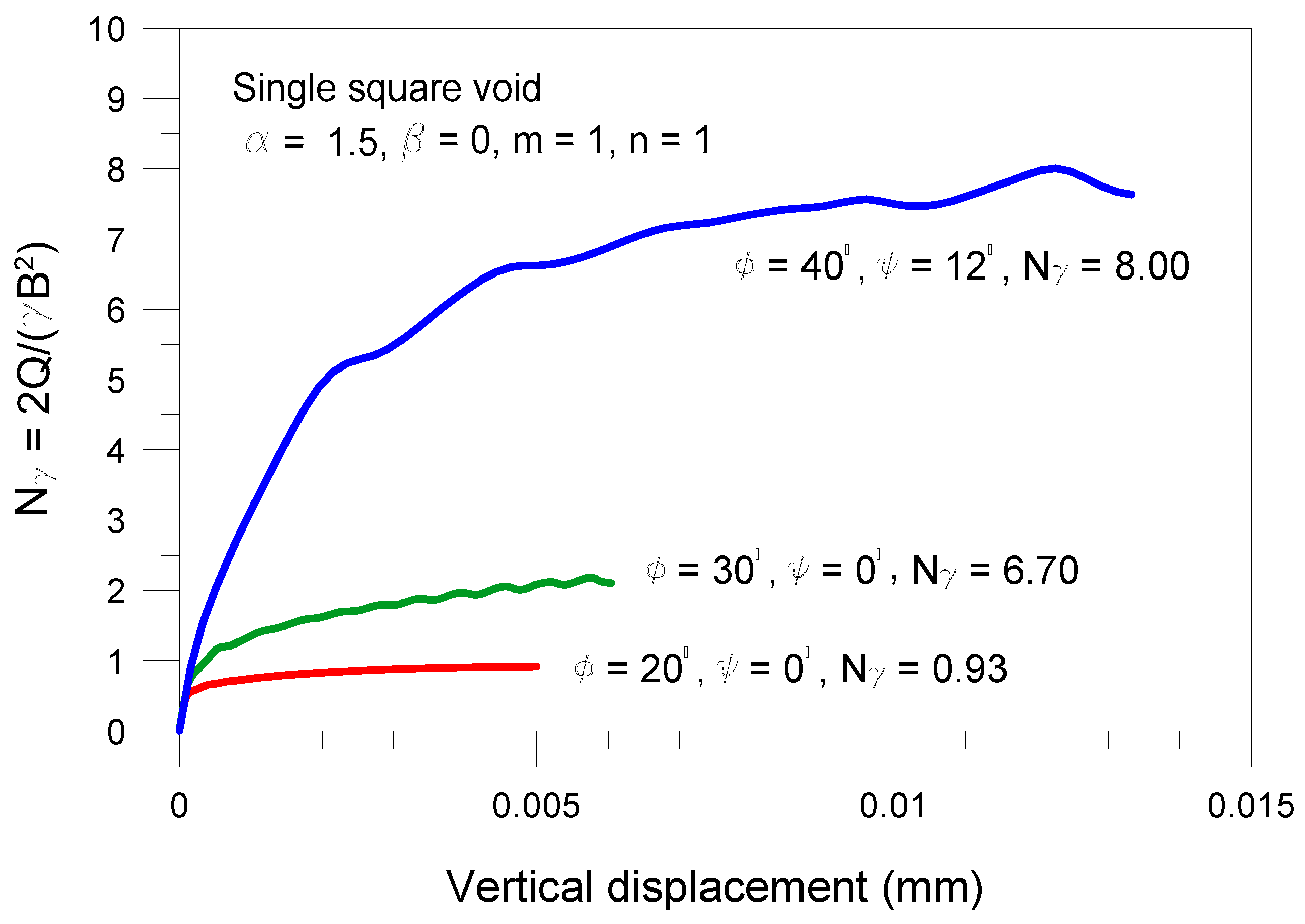
4.1. Validation

Table 1 provides the obtained values of Nγ for footings on sand without voids for different values of friction angle φ. It is noticed that the magnitude of Nγ increases continuously with increasing φ. Table 1 also compares the present Nγ values with the analyses of (1) Terzaghi [19] and Silvestri [44] using the limit equilibrium method; (2) Meyerhof [45] using the semi-empirical method; (3) Bolton and Lau [21] and Smith [46] using the method of stress characteristics; (4) Frydman and Burd [25] and Erickson and Drescher [26] using the finite difference method; (5) Hjiaj et al. [20] and Kumar and Kouzer [31] using the upper bound limit analysis; (6) Hjiaj et al. [20] and Kumar and Khatri [33] using the lower bound limit analysis; and (7) Loukidis and Salgado [42] using the finite element method. It can be seen that the computed values of Nγ are normally lower than the solutions by the upper and lower bound theorems and the methods of characteristic and limit equilibrium, and the difference is more predominant for the greater values of φ. This is mainly due to the fact that their solutions are developed by assuming that the soil behaves as a material with an associated flow rule, i.e., ψ = φ. In fact, an associate material is stronger than the non-associate one, which produces unconservative results. The current computations yield results close to the finite element solutions of Loukidis and Salgado [42], where the ψ values are the same as those used in this study. The obtained results also compare reasonably well with the results of Frydman and Burd [25] and Erickson and Drescher [26] with the consideration of ψ = 0.

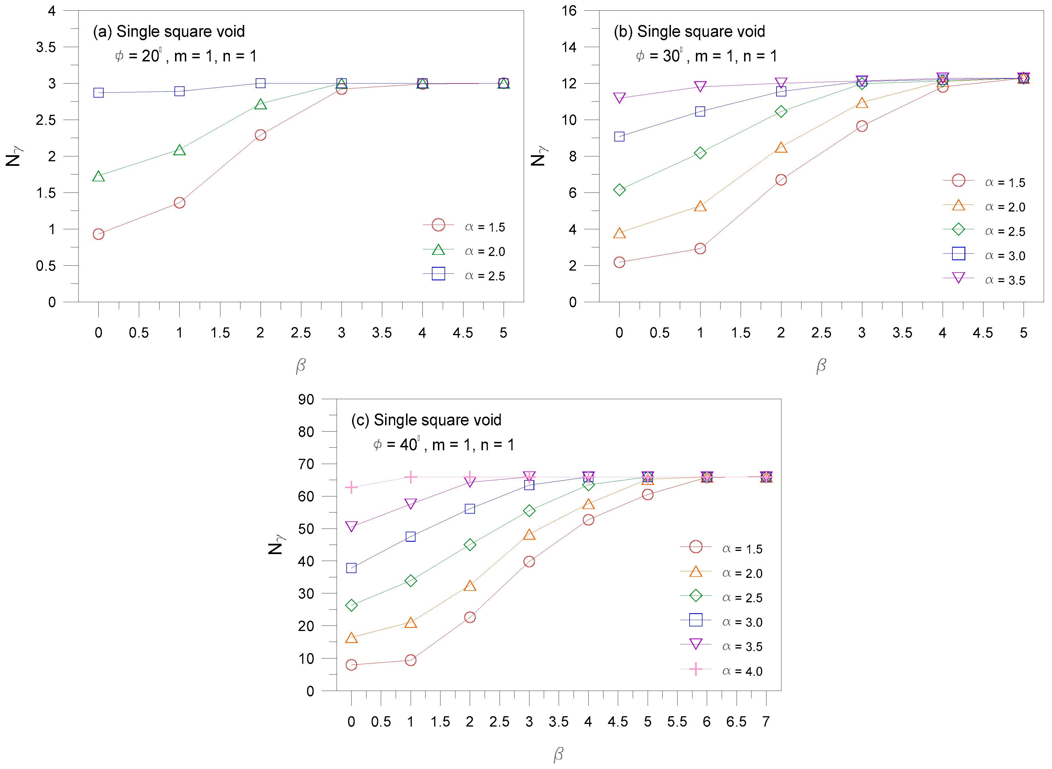
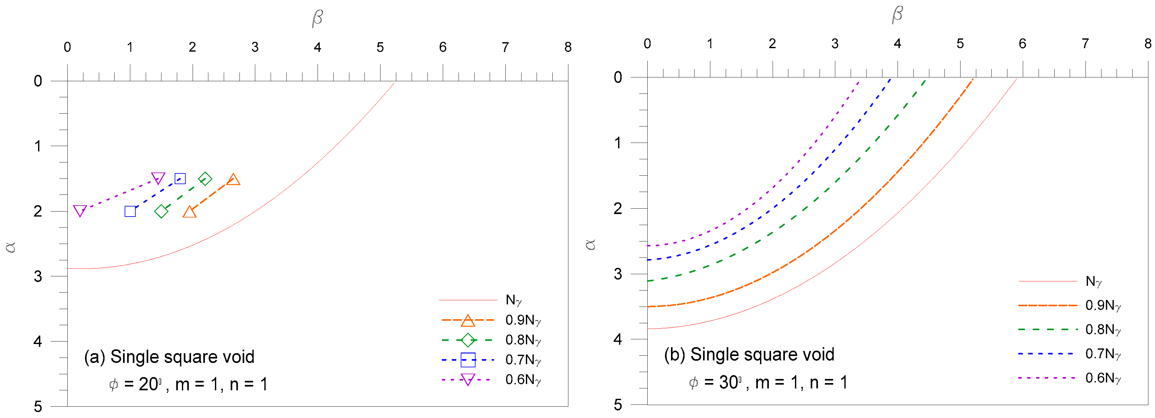
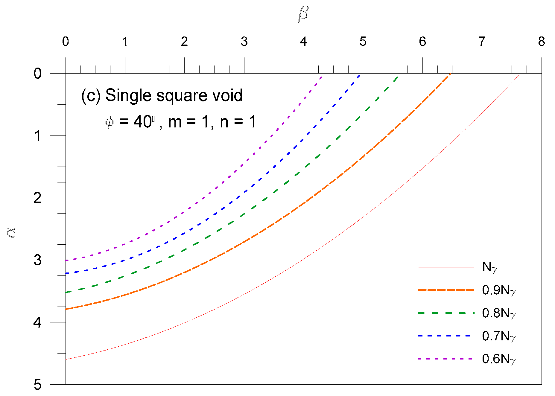
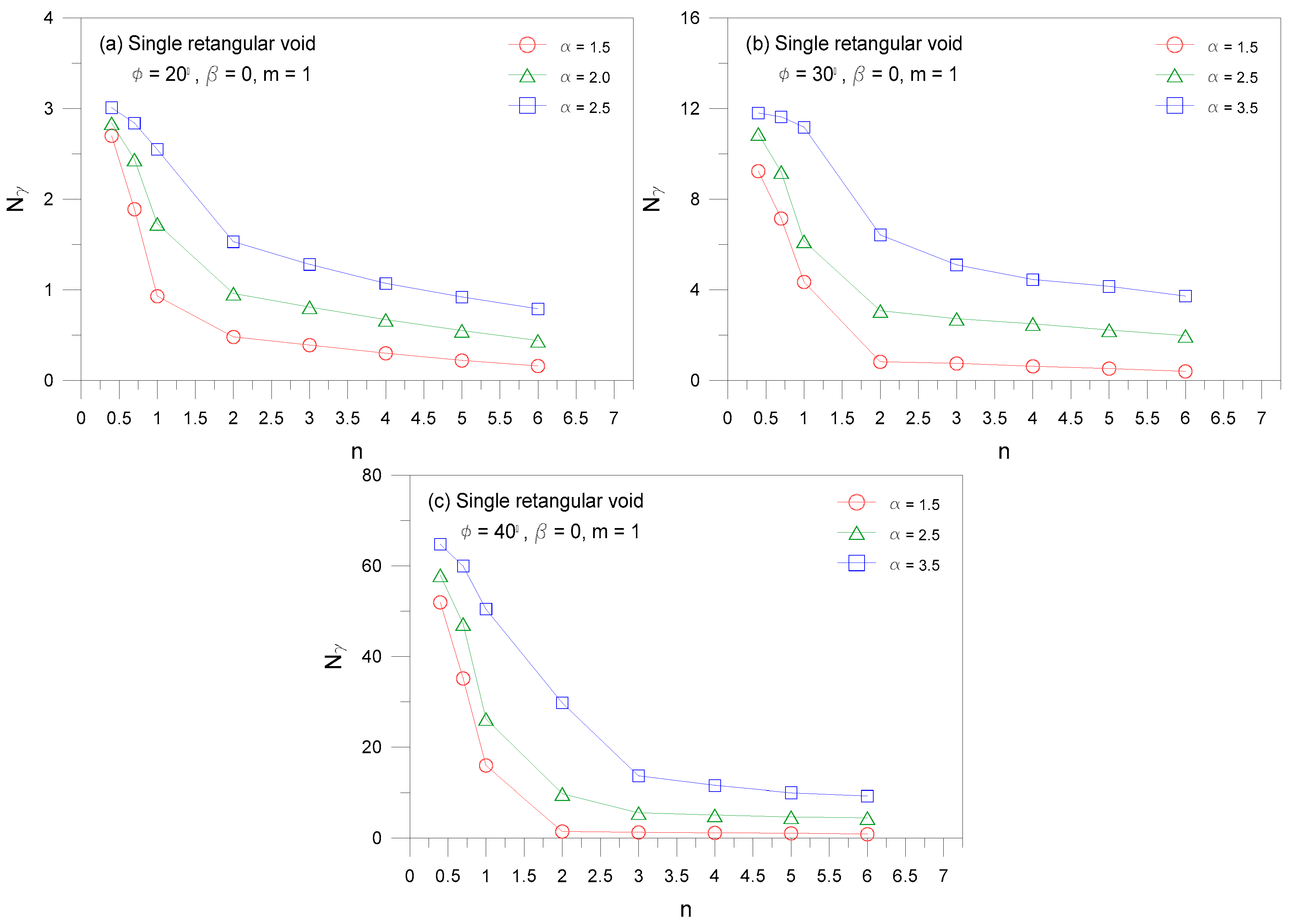
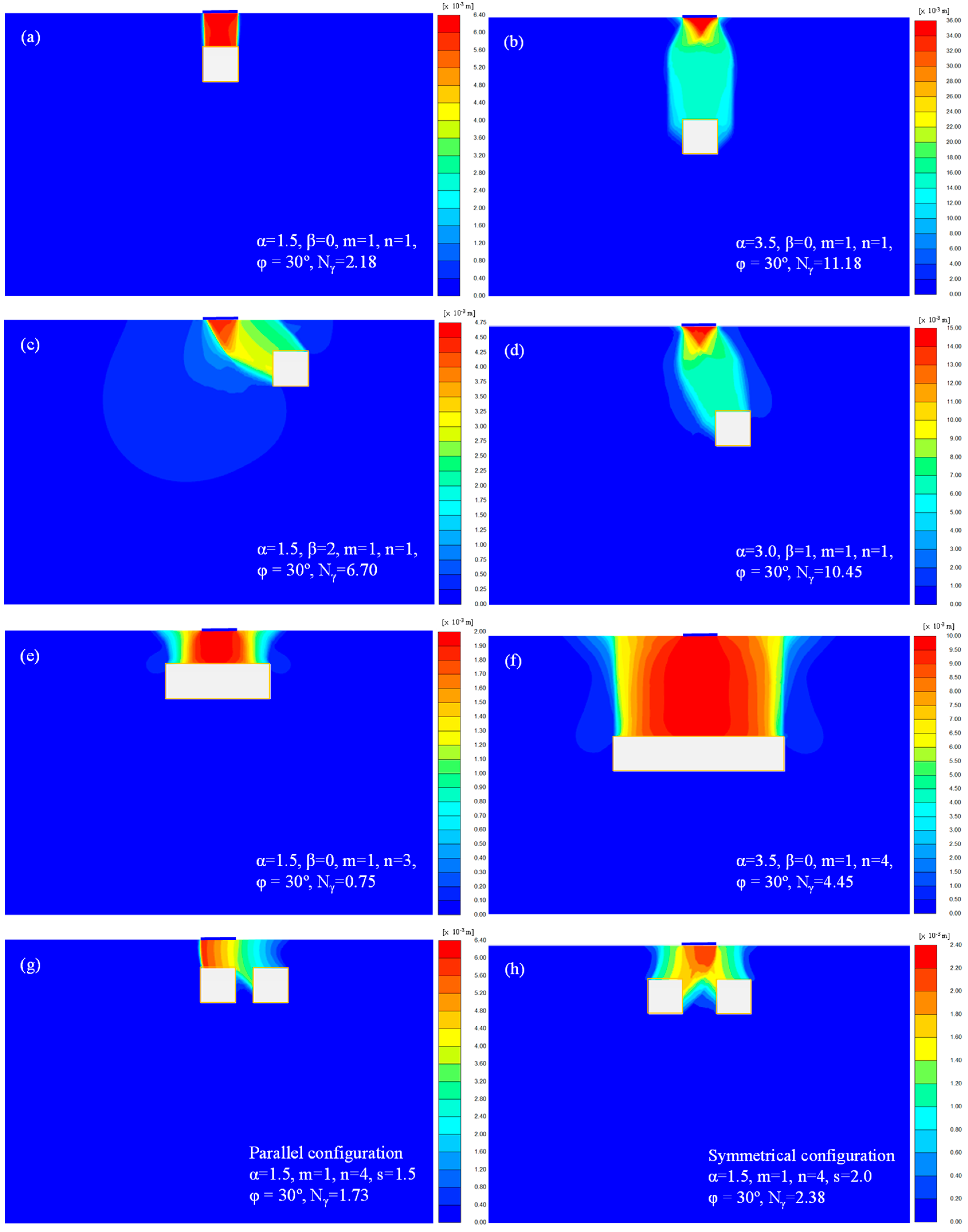
4.2. Case of Single Void

The values of Nγ for strip footings above single square void (m = 1 and n = 1) with three different values of φ = 20, 30, and 40 are presented in Figure 4, where the coupled effect of β and α is highlighted. For constant values of β and α, the magnitude of Nγ is higher for greater values of φ. It is also observed that for a given value of α, the magnitude of Nγ increases continuously with the value of β up to a limit value, and the rate of increase of Nγ with respect to β is more pronounced for lower values of α. This finding states that the influence of a subsurface void on the bearing capacity of footings reduces as the distance between the void and footing increases, and there is a certain location beyond which the void impact on the footing stability becomes negligible. Figure 4 also shows the values of βcr, representing the critical void eccentricity at which the value of Nγ becomes identical to the maximum bearing capacity factor Nγ max, decreases with increasing the value of α. It is worth noting that the lower values of Nγ are achieved for the continuous void than for the cubic void [36], and the continuous void considered herein will lead to a safe prediction of the bearing capacity.
From Figure 4, the bearing capacity distributions of strip footings above a single square void (m = 1 and n = 1) can be constructed in the form of contours of equal bearing capacity factor (1.0, 0.9, 0.8, 0.7, and 0.6Nγ). Figure 5 displays the critical void location denoted by the solid line, discussed in Figure 4. When a void is located below the line, the presence of the void is ignored. For example, it can be noticed in Figure 5a that the existence of a void does not affect much beyond a vertical location of about three times the footing width. The Nγ values at the solid line are identical to those for strip footings without a void. Figure 5 also shows the lines of constant Nγ (dashed lines), which serve as a useful qualitative conceptual aid. These lines were obtained by constructing Nγ profiles as selected points across the parameters β and α, and interpolating points of equal intensity of Nγ (0.9, 0.8, 0.7, and 0.6Nγ) in Figure 4. The dashed lines are always located inside the solid line.
Figure 6 plots the values of Nγ for strip footings centered above a single rectangular void with three different values of φ = 20, 30, and 40. As expected, the magnitude of Nγ increases with an increase in φ. It is also seen that at a given value of α, the magnitude of Nγ decreases with the increase in n, and the difference in Nγ becomes less for lower values of n.

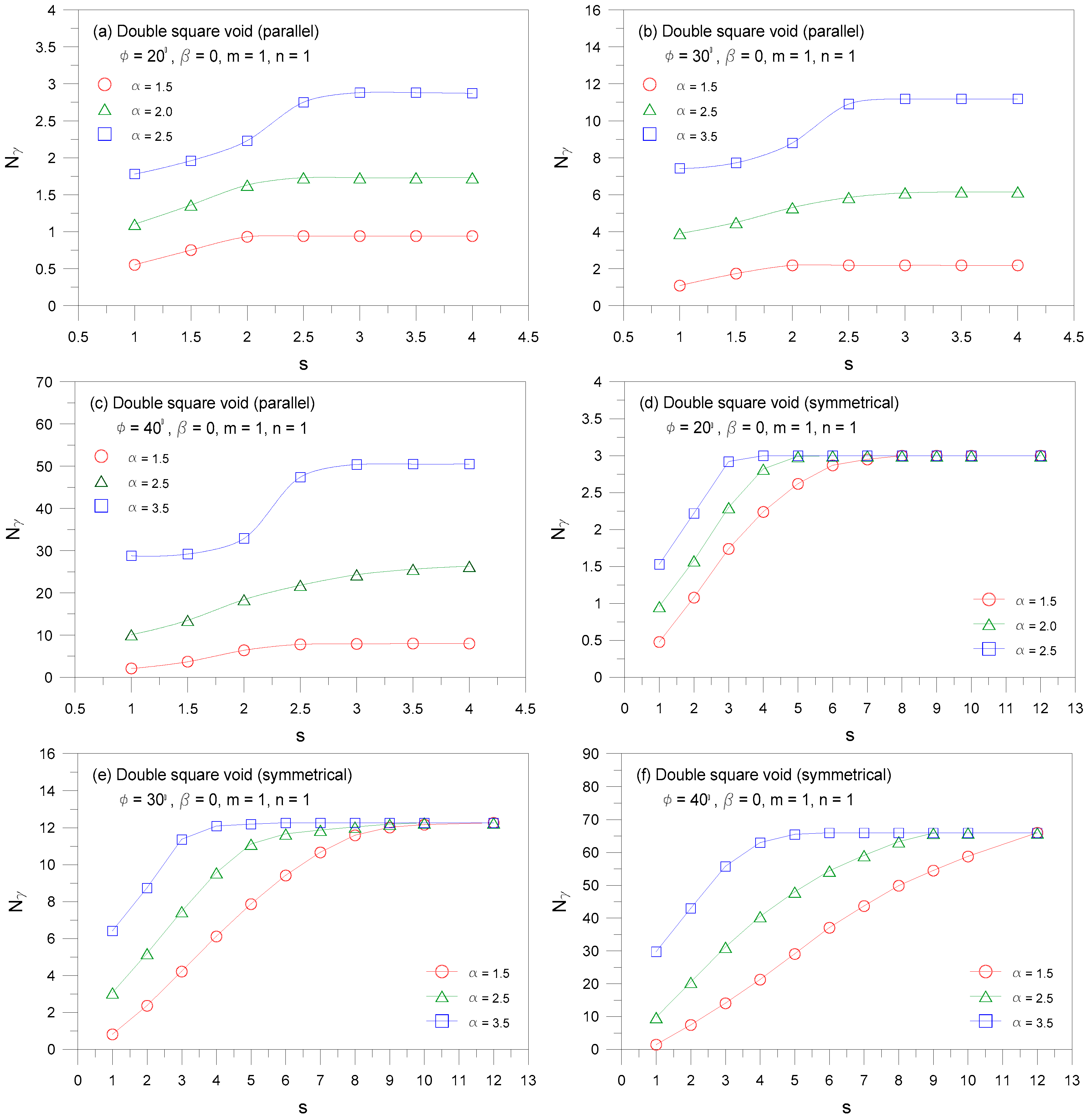
4.3. Case of Double Void

The values of Nγ for strip footings above a double square void (m = 1 and n = 1) with three different values of φ = 20, 30, and 40 are given in Figure 7, where the coupled effect of s and α is examined. The results for the two distinct void configurations, namely, parallel and symmetrical configurations are shown in Figure 7a–c and Figure 7d–e, respectively. Irrespective of void configuration, the magnitude of Nγ increases as the value of s increases, indicating that the stability of footing stability improves, as the two voids are moved further apart. This is attributable to the higher shear resistance induced by a wider pillar between the adjacent voids. Additionally, at a certain value of s, the maximum bearing capacity factor Nγ max is achieved: Especially for the parallel configuration, the Nγ max values equal those for a single void case with β = 0 presented in Figure 4. It is noted that the Nγ values for double square voids with s = 1 equal those for single rectangular voids with n = 2 presented in Figure 6. On the other hand, a comparison of Nγ values for parallel and symmetrical configurations appears to show that the Nγ values for the former are lower than those for the latter, and their difference increases with increasing s and decreasing α.

4.4. Failure Pattern

Figure 8 illustrates the finite element displacement contours at collapse for footing-above-void system. As shown, the failure mechanism is significantly dependent on the location, shape, and number of voids. For shallow square voids, the limit load is related to the well-defined roof-shaped zone, featured by the downward movement of a rigid soil block immediately above the void. This is supported by a typical roof collapse mode observed in Figure 8a. As the void location is vertically and horizontally farther from the footing, the failure mechanism becomes deeper and wider, which involves the combination of the roof and wall collapse modes given in Figure 8b–d. For the shallow rectangular void, the corresponding displacement is more complicated than that of the shallow square one and includes the rotation of soil mass above the void, as identified in Figure 8e. As the rectangular void is placed deeper and wider, the failure mechanism is dominated by the roof movement and the boundaries of the plastic area extend laterally outward (Figure 8f). The collapse modes for double voids are shown in Figure 8 g,h. It is seen that the soil displacement in the neighborhood of the individual void overlapped, leading to the decrease in collapse load. The displacement developed in the pillar between the two voids of the parallel configuration is more prominent than that of the symmetrical configuration, confirming that the symmetrical configuration has higher values of Nγ compared to the parallel configuration.

5. Conclusions

Finite element analyses of strip footings over sand with single and double continuous voids have been performed. Comparisons with published solutions for no voids have been made. Stability charts are presented in the familiar form of nondimensional bearing capacity factor Nγ, reflecting the effect of the void shape, the void distances from the footing, the spacing between the two voids and the soil friction angle. The magnitude of Nγ always decreases with increase in the values of n and m, and reduction in the values of α, β, s, and φ. By using the proposed charts and methodology, one can estimate the critical void location for design purposes. The failure pattern of footing above voids is controlled by the combination of roof and wall collapse, which differs from that of the classical bearing capacity theory.

Author Contributions

J.K.L. designed and conducted numerical analysis and wrote the draft of the paper. J.K. assisted the interpretation of the data and the writing of the paper.

Acknowledgments

The first author would like to acknowledge the support of the National Research Foundation of Korea (NRF) (Grant No. 2017R1C1B5015371).

Conflicts of Interest

The authors declare no conflict of interest.

References

  1. Holt, D.G.A.; Jefferson, I.; Braithwaite, P.A.; Chapman, D.N. Embedding sustainability into geotechnics. Part A: Methodology. Eng. Sustain. 2010, 163, 127–135. [Google Scholar] [CrossRef]
  2. Menaa, M.; Meguid, M.A.; Assaf, G. On the effects of subgrade erosion on the contact pressure distribution under rigid surface structure. J. Geotech. Geoenviron. Eng. 2009, 135, 1538–1542. [Google Scholar] [CrossRef]
  3. Baus, R.L.; Wang, M.C. Bearing capacity of strip footing above void. J. Geotech. Eng. 1983, 109, 1–14. [Google Scholar] [CrossRef]
  4. Badie, A.; Wang, M.C. Stability of spread footing above void in clay. J. Geotech. Eng. 1984, 110, 1591–1605. [Google Scholar] [CrossRef]
  5. Wang, M.C.; Hsieh, C.W. Collapse load of strip footing above circular void. J. Geotech. Eng. 1987, 113, 511–515. [Google Scholar] [CrossRef]
  6. Azam, G.; Hsieh, C.W.; Wang, M.C. Performance of strip footing on stratified soil deposit with void. J. Geotech. Eng. 1991, 117, 753–772. [Google Scholar] [CrossRef]
  7. Kiyosumi, M.; Kusakabe, O.; Ohuchi, M. Model tests and analyses of bearing capacity of strip footing on stiff ground with voids. J. Geotech. Geoenviron. Eng. 2011, 137, 363–375. [Google Scholar] [CrossRef]
  8. Lee, J.K.; Jeong, S.; Ko, J. Effect of load inclination on the undrained bearing capacity of surface spread footings above voids. Comput. Geotech. 2015, 66, 245–252. [Google Scholar] [CrossRef]
  9. Lavasan, A.; Talsaz, A.; Ghazavi, M.; Schanz, T. Behavior of shallow strip footing on twin voids. Geotech. Geo. Eng. 2016, 34, 1791–1805. [Google Scholar] [CrossRef]
  10. Zhou, H.; Zheng, G.; He, X.; Xu, X.; Zhang, T.; Yang, X. Bearing capacity of strip footings on c-φ soils with square voids. Acta Geotech. 2018, 13, 747–755. [Google Scholar] [CrossRef]
  11. Das, B.M.; Khing, K.H. Foundation on layered soil with geogrid reinforcement–effect of a void. Geotext. Geomembr. 1994, 13, 545–553. [Google Scholar] [CrossRef]
  12. Wang, M.C.; Feng, Y.X.; Jao, M. Stability of geosynthetic-reinforced soil above a cavity. Geotext. Geomembr. 1996, 14, 95–109. [Google Scholar] [CrossRef]
  13. Agaiby, S.W.; Jones, C.J.F.P. Design of reinforced fill systems to support footings overlying cavities. Geotext. Geomembr. 1996, 14, 57–72. [Google Scholar] [CrossRef]
  14. Sireesh, S.; Sitharam, T.G.; Dash, S.K. Bearing capacity of circular footing on geocell-sand mattress overlying clay bed with void. Geotext. Geomembr. 2009, 27, 89–98. [Google Scholar] [CrossRef]
  15. Mohamed, M.H.A. Two dimensional experimental study for the behavior of surface footings on unreinforced and reinforced sand beds overlying soft pockets. Geotext. Geomembr. 2010, 28, 589–596. [Google Scholar] [CrossRef]
  16. Tafresho, S.N.M.; Khalaj, O.; Halvaee, M. Experimental study of a shallow strip footing on geogrid-reinforced sand bed above a void. Geosynth. Int. 2011, 18, 178–195. [Google Scholar] [CrossRef]
  17. Asakereh, A.; Ghazavi, M.; Tafreshi, S.N.M. Cyclic response of footing on geogrid-reinforced sand with void. Soils Found 2013, 53, 363–374. [Google Scholar] [CrossRef] [Green Version]
  18. Lai, F.; Chen, F.; Li, D. Bearing capacity characteristics and failure modes of low geosynthetic-reinforced embankments overlying voids. Int. J. Geomech. 2018, 18, 0401805. [Google Scholar] [CrossRef]
  19. Terzaghi, K. Theoretical Soil Mechanics; Wiley: New York, NY, USA, 1943. [Google Scholar]
  20. Hjiaj, M.; Lyamin, A.V.; Sloan, S.W. Numerical limit analysis solutions for the bearing capacity factor Nγ. Int. J. Solids Struct. 2005, 42, 1681–1704. [Google Scholar] [CrossRef]
  21. Bolton, M.D.; Lau, C.K. Vertical bearing capacity factors for circular and strip footings on Mohr-Coulomb soil. Can. Geotech. J. 1993, 30, 1024–1033. [Google Scholar] [CrossRef]
  22. Prandtl, L. Uber die Eindringungs-festigkeit (Harte) plastischer Baustoffe und die Festigkeit von Schneiden. Z. Angew. Math. Mech. 1921, 1, 15–20. [Google Scholar] [CrossRef]
  23. Griffiths, D.V. Computation of bearing capacity factors using finite elements. Geotechnique 1982, 32, 195–202. [Google Scholar] [CrossRef]
  24. Manoharan, N.; Dasgupta, S.P. Bearing capacity of surface footings by finite elements. Comput. Geotech. 1995, 54, 563–586. [Google Scholar] [CrossRef]
  25. Frydman, S.; Burd, H.J. Numerical studies of bearing capacity factor Nγ. J. Geotech. Geoenviron. Eng. 1997, 123, 20–29. [Google Scholar] [CrossRef]
  26. Erickson, H.L.; Drescher, A. Bearing capacity of circular footings. J. Geotech. Geoenviron. Eng. 2002, 128, 38–43. [Google Scholar] [CrossRef]
  27. Diaz-Segura, E.G. Assessment of the range of variation of Nγ from 60 estimation methods of footings on sand. Can. Geotech. J. 2013, 50, 793–800. [Google Scholar] [CrossRef]
  28. Yin, J.; Wang, Y.; Selvadurai, A.P.S. Influence of nonassociativity on the bearing capacity of a strip footing. J. Geotech. Geoenviron. Eng. 2001, 127, 985–989. [Google Scholar] [CrossRef]
  29. Cassidy, M.J.; Houlsby, G.T. Vertical bearing capacity factors for conical footings on sand. Geotechnique 2002, 52, 687–692. [Google Scholar] [CrossRef]
  30. Ukritchon, B.; Whittle, A.J.; Klangvijit, C. Calculations of bearing capacity factor Nγ using numerical limit analyses. J. Geotech. Geoenviron. Eng. 2003, 129, 468–474. [Google Scholar] [CrossRef]
  31. Kumar, J.; Kouzer, K.M. Effect of footing roughness on bearing capacity factor Nγ. J. Geotech. Geoenviron. Eng. 2007, 133, 502–511. [Google Scholar] [CrossRef]
  32. Lyamin, A.V.; Salgado, R.; Sloan, S.W.; Perzzi, M. Two- and three-dimensional bearing capacity of footings in sand. Geotechnique 2007, 57, 647–662. [Google Scholar] [CrossRef] [Green Version]
  33. Kumar, J.; Khatri, V.N. Effect of footing roughness on lower bound Nγ values. Int. J. Geomech. 2008, 8, 176–187. [Google Scholar] [CrossRef]
  34. Loukidis, D.; Salgado, R. Effect of relative density and stress level on the bearing capacity of footings on sand. Geotechnique 2011, 61, 107–119. [Google Scholar] [CrossRef] [Green Version]
  35. Ma, Z.; Liao, H.; Dang, F. Influence of intermediate principal stress on the bearing capacity of strip and circular footings. J. Eng. Mech. 2014, 140, 04014041. [Google Scholar] [CrossRef]
  36. Wang, M.C.; Badie, A.M. Effect of underground void of foundation stability. J. Geotech. Eng. 1985, 111, 1008–1019. [Google Scholar] [CrossRef]
  37. Kiyosymi, M.; Kusakabe, O.; Ohuchi, M.; Peng, F.L. Yielding pressure of spread footing above multiple voids. J. Geotech. Geoenviron. Eng. 2007, 133, 1522–1531. [Google Scholar] [CrossRef]
  38. Lee, J.K.; Jeong, S.; Ko, J. Undrained stability of surface strip footings above voids. Comput. Geotech. 2014, 62, 128–135. [Google Scholar] [CrossRef]
  39. Xiao, Y.; Zhao, M.; Zhoa, H. Undrained stability of strip footing above voids in two-layered clays by finite element limit analysis. Comput. Geotech. 2018, 97, 124–133. [Google Scholar] [CrossRef]
  40. Xiao, Y.; Zhao, M.; Zhoa, H.; Zhang, R. Finite element limit analysis of the bearing capacity of strip footing on a rock mass with voids. Int. J. Geomech. 2018, 18, 04018108. [Google Scholar] [CrossRef]
  41. Bolton, M.D. Strength and dilatancy of sands. Geotechnique 1986, 36, 65–78. [Google Scholar] [CrossRef]
  42. Loukidis, D.; Salgado, R. Bearing capacity of strip and circular footings in sand using finite elements. Comput. Geotech. 2009, 36, 871–879. [Google Scholar] [CrossRef]
  43. Drescher, A.; Detournay, E. Limit load in translational failure mechanisms for associative and non-associative materials. Geotechnique 1993, 43, 443–456. [Google Scholar] [CrossRef]
  44. Silvestri, V.A. limit equilibrium solution for bearing capacity of strip foundations on sand. Can. Geotech. J. 2003, 40, 351–361. [Google Scholar] [CrossRef]
  45. Meyerhof, G.G. Some recent research on the bearing capacity of foundations. Can. Geotech. J. 1963, 1, 16–31. [Google Scholar] [CrossRef]
  46. Smith, C.C. Complete limiting stress solutions for the bearing capacity of strip footings on a Mohr-Coulomb soil. Geotechnique 2005, 55, 607–612. [Google Scholar] [CrossRef]
Figure 1. Problem definition and notation.
Sustainability 11 03966 g001
Figure 2. Finite element mesh with boundary conditions used in analysis.
Sustainability 11 03966 g002
Figure 3. Bearing capacity factor Nγ versus vertical displacement for different friction angle φ.
Sustainability 11 03966 g003
Figure 4. Bearing capacity factor Nγ for a single square void.
Sustainability 11 03966 g004
Figure 5. Critical void location for a single square void.
Sustainability 11 03966 g005aSustainability 11 03966 g005b
Figure 6. Bearing capacity factor Nγ for a single rectangular void.
Sustainability 11 03966 g006
Figure 7. Bearing capacity factor Nγ for double voids with parallel and symmetrical configurations.
Sustainability 11 03966 g007
Figure 8. Contours of displacement for bearing capacity factor Nγ.
Sustainability 11 03966 g008
Table 1. Comparison of Nγ values for rough footings on sand without voids.
ReferenceMethodφ ()
203040
Terzaghi (1943)Limit equilibrium4.8020.0-
Meyerhof (1963)Semi-empirical2.8715.793.7
Bolton and Lau (1993)Method of characteristics5.9723.6121
Frydman and Burd (1997)Finite difference-16.773.0
Erickson and Drescher (2002)Finite difference2.5-73.0
Silvestri (2003)Limit equilibrium-19.5107
Smith (2005)Method of characteristics2.8414.885.6
Hjiaj et al. (2005)Upper bound limit analysis2.9615.288.4
Hjiaj et al. (2005)Lower bound limit analysis2.8214.683.3
Kumar and Kouzer (2007)Upper bound limit analysis3.1616.598.5
Kumar and Khatri (2008)Lower bound limit analysis2.6513.777.9
Loukidis and Salgado (2009)Finite element-12.967.9
This studyFinite element3.0111.965.9

